WO2013018198A1 - 運転支援装置 - Google Patents
運転支援装置 Download PDFInfo
- Publication number
- WO2013018198A1 WO2013018198A1 PCT/JP2011/067694 JP2011067694W WO2013018198A1 WO 2013018198 A1 WO2013018198 A1 WO 2013018198A1 JP 2011067694 W JP2011067694 W JP 2011067694W WO 2013018198 A1 WO2013018198 A1 WO 2013018198A1
- Authority
- WO
- WIPO (PCT)
- Prior art keywords
- vehicle
- driving
- timing
- support
- target
- Prior art date
Links
- 230000001133 acceleration Effects 0.000 claims description 16
- 230000009471 action Effects 0.000 claims description 4
- 238000002485 combustion reaction Methods 0.000 claims description 4
- 230000005540 biological transmission Effects 0.000 description 27
- 230000008929 regeneration Effects 0.000 description 23
- 238000011069 regeneration method Methods 0.000 description 23
- 239000000446 fuel Substances 0.000 description 20
- 238000004891 communication Methods 0.000 description 17
- 238000010586 diagram Methods 0.000 description 13
- 230000006872 improvement Effects 0.000 description 12
- 230000001172 regenerating effect Effects 0.000 description 12
- 230000008859 change Effects 0.000 description 11
- 230000000694 effects Effects 0.000 description 11
- 230000006698 induction Effects 0.000 description 10
- 238000001514 detection method Methods 0.000 description 6
- 230000006870 function Effects 0.000 description 6
- 230000000007 visual effect Effects 0.000 description 6
- 238000013459 approach Methods 0.000 description 4
- 230000006399 behavior Effects 0.000 description 4
- 238000011156 evaluation Methods 0.000 description 4
- 238000010248 power generation Methods 0.000 description 4
- 230000035484 reaction time Effects 0.000 description 3
- 230000004044 response Effects 0.000 description 3
- 208000031427 Foetal heart rate deceleration Diseases 0.000 description 1
- 230000033228 biological regulation Effects 0.000 description 1
- 238000006243 chemical reaction Methods 0.000 description 1
- 239000000470 constituent Substances 0.000 description 1
- 238000010276 construction Methods 0.000 description 1
- 230000007812 deficiency Effects 0.000 description 1
- 238000007599 discharging Methods 0.000 description 1
- 230000009977 dual effect Effects 0.000 description 1
- 238000002347 injection Methods 0.000 description 1
- 239000007924 injection Substances 0.000 description 1
- 239000004973 liquid crystal related substance Substances 0.000 description 1
- 230000007246 mechanism Effects 0.000 description 1
- 238000012986 modification Methods 0.000 description 1
- 230000004048 modification Effects 0.000 description 1
- 230000003287 optical effect Effects 0.000 description 1
- 238000012545 processing Methods 0.000 description 1
- 238000011084 recovery Methods 0.000 description 1
- 230000003068 static effect Effects 0.000 description 1
- 230000007704 transition Effects 0.000 description 1
Images


Classifications
-
- B—PERFORMING OPERATIONS; TRANSPORTING
- B60—VEHICLES IN GENERAL
- B60W—CONJOINT CONTROL OF VEHICLE SUB-UNITS OF DIFFERENT TYPE OR DIFFERENT FUNCTION; CONTROL SYSTEMS SPECIALLY ADAPTED FOR HYBRID VEHICLES; ROAD VEHICLE DRIVE CONTROL SYSTEMS FOR PURPOSES NOT RELATED TO THE CONTROL OF A PARTICULAR SUB-UNIT
- B60W20/00—Control systems specially adapted for hybrid vehicles
-
- B—PERFORMING OPERATIONS; TRANSPORTING
- B60—VEHICLES IN GENERAL
- B60K—ARRANGEMENT OR MOUNTING OF PROPULSION UNITS OR OF TRANSMISSIONS IN VEHICLES; ARRANGEMENT OR MOUNTING OF PLURAL DIVERSE PRIME-MOVERS IN VEHICLES; AUXILIARY DRIVES FOR VEHICLES; INSTRUMENTATION OR DASHBOARDS FOR VEHICLES; ARRANGEMENTS IN CONNECTION WITH COOLING, AIR INTAKE, GAS EXHAUST OR FUEL SUPPLY OF PROPULSION UNITS IN VEHICLES
- B60K35/00—Instruments specially adapted for vehicles; Arrangement of instruments in or on vehicles
- B60K35/20—Output arrangements, i.e. from vehicle to user, associated with vehicle functions or specially adapted therefor
- B60K35/28—Output arrangements, i.e. from vehicle to user, associated with vehicle functions or specially adapted therefor characterised by the type of the output information, e.g. video entertainment or vehicle dynamics information; characterised by the purpose of the output information, e.g. for attracting the attention of the driver
-
- B—PERFORMING OPERATIONS; TRANSPORTING
- B60—VEHICLES IN GENERAL
- B60L—PROPULSION OF ELECTRICALLY-PROPELLED VEHICLES; SUPPLYING ELECTRIC POWER FOR AUXILIARY EQUIPMENT OF ELECTRICALLY-PROPELLED VEHICLES; ELECTRODYNAMIC BRAKE SYSTEMS FOR VEHICLES IN GENERAL; MAGNETIC SUSPENSION OR LEVITATION FOR VEHICLES; MONITORING OPERATING VARIABLES OF ELECTRICALLY-PROPELLED VEHICLES; ELECTRIC SAFETY DEVICES FOR ELECTRICALLY-PROPELLED VEHICLES
- B60L15/00—Methods, circuits, or devices for controlling the traction-motor speed of electrically-propelled vehicles
- B60L15/20—Methods, circuits, or devices for controlling the traction-motor speed of electrically-propelled vehicles for control of the vehicle or its driving motor to achieve a desired performance, e.g. speed, torque, programmed variation of speed
- B60L15/2009—Methods, circuits, or devices for controlling the traction-motor speed of electrically-propelled vehicles for control of the vehicle or its driving motor to achieve a desired performance, e.g. speed, torque, programmed variation of speed for braking
-
- B—PERFORMING OPERATIONS; TRANSPORTING
- B60—VEHICLES IN GENERAL
- B60L—PROPULSION OF ELECTRICALLY-PROPELLED VEHICLES; SUPPLYING ELECTRIC POWER FOR AUXILIARY EQUIPMENT OF ELECTRICALLY-PROPELLED VEHICLES; ELECTRODYNAMIC BRAKE SYSTEMS FOR VEHICLES IN GENERAL; MAGNETIC SUSPENSION OR LEVITATION FOR VEHICLES; MONITORING OPERATING VARIABLES OF ELECTRICALLY-PROPELLED VEHICLES; ELECTRIC SAFETY DEVICES FOR ELECTRICALLY-PROPELLED VEHICLES
- B60L15/00—Methods, circuits, or devices for controlling the traction-motor speed of electrically-propelled vehicles
- B60L15/20—Methods, circuits, or devices for controlling the traction-motor speed of electrically-propelled vehicles for control of the vehicle or its driving motor to achieve a desired performance, e.g. speed, torque, programmed variation of speed
- B60L15/2045—Methods, circuits, or devices for controlling the traction-motor speed of electrically-propelled vehicles for control of the vehicle or its driving motor to achieve a desired performance, e.g. speed, torque, programmed variation of speed for optimising the use of energy
-
- B—PERFORMING OPERATIONS; TRANSPORTING
- B60—VEHICLES IN GENERAL
- B60W—CONJOINT CONTROL OF VEHICLE SUB-UNITS OF DIFFERENT TYPE OR DIFFERENT FUNCTION; CONTROL SYSTEMS SPECIALLY ADAPTED FOR HYBRID VEHICLES; ROAD VEHICLE DRIVE CONTROL SYSTEMS FOR PURPOSES NOT RELATED TO THE CONTROL OF A PARTICULAR SUB-UNIT
- B60W10/00—Conjoint control of vehicle sub-units of different type or different function
- B60W10/04—Conjoint control of vehicle sub-units of different type or different function including control of propulsion units
- B60W10/06—Conjoint control of vehicle sub-units of different type or different function including control of propulsion units including control of combustion engines
-
- B—PERFORMING OPERATIONS; TRANSPORTING
- B60—VEHICLES IN GENERAL
- B60W—CONJOINT CONTROL OF VEHICLE SUB-UNITS OF DIFFERENT TYPE OR DIFFERENT FUNCTION; CONTROL SYSTEMS SPECIALLY ADAPTED FOR HYBRID VEHICLES; ROAD VEHICLE DRIVE CONTROL SYSTEMS FOR PURPOSES NOT RELATED TO THE CONTROL OF A PARTICULAR SUB-UNIT
- B60W10/00—Conjoint control of vehicle sub-units of different type or different function
- B60W10/04—Conjoint control of vehicle sub-units of different type or different function including control of propulsion units
- B60W10/08—Conjoint control of vehicle sub-units of different type or different function including control of propulsion units including control of electric propulsion units, e.g. motors or generators
-
- B—PERFORMING OPERATIONS; TRANSPORTING
- B60—VEHICLES IN GENERAL
- B60W—CONJOINT CONTROL OF VEHICLE SUB-UNITS OF DIFFERENT TYPE OR DIFFERENT FUNCTION; CONTROL SYSTEMS SPECIALLY ADAPTED FOR HYBRID VEHICLES; ROAD VEHICLE DRIVE CONTROL SYSTEMS FOR PURPOSES NOT RELATED TO THE CONTROL OF A PARTICULAR SUB-UNIT
- B60W10/00—Conjoint control of vehicle sub-units of different type or different function
- B60W10/18—Conjoint control of vehicle sub-units of different type or different function including control of braking systems
-
- B—PERFORMING OPERATIONS; TRANSPORTING
- B60—VEHICLES IN GENERAL
- B60W—CONJOINT CONTROL OF VEHICLE SUB-UNITS OF DIFFERENT TYPE OR DIFFERENT FUNCTION; CONTROL SYSTEMS SPECIALLY ADAPTED FOR HYBRID VEHICLES; ROAD VEHICLE DRIVE CONTROL SYSTEMS FOR PURPOSES NOT RELATED TO THE CONTROL OF A PARTICULAR SUB-UNIT
- B60W20/00—Control systems specially adapted for hybrid vehicles
- B60W20/10—Controlling the power contribution of each of the prime movers to meet required power demand
- B60W20/13—Controlling the power contribution of each of the prime movers to meet required power demand in order to stay within battery power input or output limits; in order to prevent overcharging or battery depletion
- B60W20/14—Controlling the power contribution of each of the prime movers to meet required power demand in order to stay within battery power input or output limits; in order to prevent overcharging or battery depletion in conjunction with braking regeneration
-
- B—PERFORMING OPERATIONS; TRANSPORTING
- B60—VEHICLES IN GENERAL
- B60W—CONJOINT CONTROL OF VEHICLE SUB-UNITS OF DIFFERENT TYPE OR DIFFERENT FUNCTION; CONTROL SYSTEMS SPECIALLY ADAPTED FOR HYBRID VEHICLES; ROAD VEHICLE DRIVE CONTROL SYSTEMS FOR PURPOSES NOT RELATED TO THE CONTROL OF A PARTICULAR SUB-UNIT
- B60W30/00—Purposes of road vehicle drive control systems not related to the control of a particular sub-unit, e.g. of systems using conjoint control of vehicle sub-units
- B60W30/18—Propelling the vehicle
- B60W30/18009—Propelling the vehicle related to particular drive situations
- B60W30/18109—Braking
- B60W30/18127—Regenerative braking
-
- B—PERFORMING OPERATIONS; TRANSPORTING
- B60—VEHICLES IN GENERAL
- B60K—ARRANGEMENT OR MOUNTING OF PROPULSION UNITS OR OF TRANSMISSIONS IN VEHICLES; ARRANGEMENT OR MOUNTING OF PLURAL DIVERSE PRIME-MOVERS IN VEHICLES; AUXILIARY DRIVES FOR VEHICLES; INSTRUMENTATION OR DASHBOARDS FOR VEHICLES; ARRANGEMENTS IN CONNECTION WITH COOLING, AIR INTAKE, GAS EXHAUST OR FUEL SUPPLY OF PROPULSION UNITS IN VEHICLES
- B60K2360/00—Indexing scheme associated with groups B60K35/00 or B60K37/00 relating to details of instruments or dashboards
- B60K2360/16—Type of output information
- B60K2360/172—Driving mode indication
-
- B—PERFORMING OPERATIONS; TRANSPORTING
- B60—VEHICLES IN GENERAL
- B60L—PROPULSION OF ELECTRICALLY-PROPELLED VEHICLES; SUPPLYING ELECTRIC POWER FOR AUXILIARY EQUIPMENT OF ELECTRICALLY-PROPELLED VEHICLES; ELECTRODYNAMIC BRAKE SYSTEMS FOR VEHICLES IN GENERAL; MAGNETIC SUSPENSION OR LEVITATION FOR VEHICLES; MONITORING OPERATING VARIABLES OF ELECTRICALLY-PROPELLED VEHICLES; ELECTRIC SAFETY DEVICES FOR ELECTRICALLY-PROPELLED VEHICLES
- B60L2240/00—Control parameters of input or output; Target parameters
- B60L2240/10—Vehicle control parameters
- B60L2240/12—Speed
-
- B—PERFORMING OPERATIONS; TRANSPORTING
- B60—VEHICLES IN GENERAL
- B60L—PROPULSION OF ELECTRICALLY-PROPELLED VEHICLES; SUPPLYING ELECTRIC POWER FOR AUXILIARY EQUIPMENT OF ELECTRICALLY-PROPELLED VEHICLES; ELECTRODYNAMIC BRAKE SYSTEMS FOR VEHICLES IN GENERAL; MAGNETIC SUSPENSION OR LEVITATION FOR VEHICLES; MONITORING OPERATING VARIABLES OF ELECTRICALLY-PROPELLED VEHICLES; ELECTRIC SAFETY DEVICES FOR ELECTRICALLY-PROPELLED VEHICLES
- B60L2240/00—Control parameters of input or output; Target parameters
- B60L2240/10—Vehicle control parameters
- B60L2240/14—Acceleration
-
- B—PERFORMING OPERATIONS; TRANSPORTING
- B60—VEHICLES IN GENERAL
- B60L—PROPULSION OF ELECTRICALLY-PROPELLED VEHICLES; SUPPLYING ELECTRIC POWER FOR AUXILIARY EQUIPMENT OF ELECTRICALLY-PROPELLED VEHICLES; ELECTRODYNAMIC BRAKE SYSTEMS FOR VEHICLES IN GENERAL; MAGNETIC SUSPENSION OR LEVITATION FOR VEHICLES; MONITORING OPERATING VARIABLES OF ELECTRICALLY-PROPELLED VEHICLES; ELECTRIC SAFETY DEVICES FOR ELECTRICALLY-PROPELLED VEHICLES
- B60L2240/00—Control parameters of input or output; Target parameters
- B60L2240/40—Drive Train control parameters
- B60L2240/42—Drive Train control parameters related to electric machines
- B60L2240/423—Torque
-
- B—PERFORMING OPERATIONS; TRANSPORTING
- B60—VEHICLES IN GENERAL
- B60L—PROPULSION OF ELECTRICALLY-PROPELLED VEHICLES; SUPPLYING ELECTRIC POWER FOR AUXILIARY EQUIPMENT OF ELECTRICALLY-PROPELLED VEHICLES; ELECTRODYNAMIC BRAKE SYSTEMS FOR VEHICLES IN GENERAL; MAGNETIC SUSPENSION OR LEVITATION FOR VEHICLES; MONITORING OPERATING VARIABLES OF ELECTRICALLY-PROPELLED VEHICLES; ELECTRIC SAFETY DEVICES FOR ELECTRICALLY-PROPELLED VEHICLES
- B60L2240/00—Control parameters of input or output; Target parameters
- B60L2240/40—Drive Train control parameters
- B60L2240/44—Drive Train control parameters related to combustion engines
- B60L2240/443—Torque
-
- B—PERFORMING OPERATIONS; TRANSPORTING
- B60—VEHICLES IN GENERAL
- B60L—PROPULSION OF ELECTRICALLY-PROPELLED VEHICLES; SUPPLYING ELECTRIC POWER FOR AUXILIARY EQUIPMENT OF ELECTRICALLY-PROPELLED VEHICLES; ELECTRODYNAMIC BRAKE SYSTEMS FOR VEHICLES IN GENERAL; MAGNETIC SUSPENSION OR LEVITATION FOR VEHICLES; MONITORING OPERATING VARIABLES OF ELECTRICALLY-PROPELLED VEHICLES; ELECTRIC SAFETY DEVICES FOR ELECTRICALLY-PROPELLED VEHICLES
- B60L2240/00—Control parameters of input or output; Target parameters
- B60L2240/70—Interactions with external data bases, e.g. traffic centres
-
- B—PERFORMING OPERATIONS; TRANSPORTING
- B60—VEHICLES IN GENERAL
- B60L—PROPULSION OF ELECTRICALLY-PROPELLED VEHICLES; SUPPLYING ELECTRIC POWER FOR AUXILIARY EQUIPMENT OF ELECTRICALLY-PROPELLED VEHICLES; ELECTRODYNAMIC BRAKE SYSTEMS FOR VEHICLES IN GENERAL; MAGNETIC SUSPENSION OR LEVITATION FOR VEHICLES; MONITORING OPERATING VARIABLES OF ELECTRICALLY-PROPELLED VEHICLES; ELECTRIC SAFETY DEVICES FOR ELECTRICALLY-PROPELLED VEHICLES
- B60L2250/00—Driver interactions
- B60L2250/16—Driver interactions by display
-
- B—PERFORMING OPERATIONS; TRANSPORTING
- B60—VEHICLES IN GENERAL
- B60W—CONJOINT CONTROL OF VEHICLE SUB-UNITS OF DIFFERENT TYPE OR DIFFERENT FUNCTION; CONTROL SYSTEMS SPECIALLY ADAPTED FOR HYBRID VEHICLES; ROAD VEHICLE DRIVE CONTROL SYSTEMS FOR PURPOSES NOT RELATED TO THE CONTROL OF A PARTICULAR SUB-UNIT
- B60W50/00—Details of control systems for road vehicle drive control not related to the control of a particular sub-unit, e.g. process diagnostic or vehicle driver interfaces
- B60W50/08—Interaction between the driver and the control system
- B60W50/14—Means for informing the driver, warning the driver or prompting a driver intervention
- B60W2050/146—Display means
-
- B—PERFORMING OPERATIONS; TRANSPORTING
- B60—VEHICLES IN GENERAL
- B60W—CONJOINT CONTROL OF VEHICLE SUB-UNITS OF DIFFERENT TYPE OR DIFFERENT FUNCTION; CONTROL SYSTEMS SPECIALLY ADAPTED FOR HYBRID VEHICLES; ROAD VEHICLE DRIVE CONTROL SYSTEMS FOR PURPOSES NOT RELATED TO THE CONTROL OF A PARTICULAR SUB-UNIT
- B60W2555/00—Input parameters relating to exterior conditions, not covered by groups B60W2552/00, B60W2554/00
- B60W2555/60—Traffic rules, e.g. speed limits or right of way
-
- B—PERFORMING OPERATIONS; TRANSPORTING
- B60—VEHICLES IN GENERAL
- B60W—CONJOINT CONTROL OF VEHICLE SUB-UNITS OF DIFFERENT TYPE OR DIFFERENT FUNCTION; CONTROL SYSTEMS SPECIALLY ADAPTED FOR HYBRID VEHICLES; ROAD VEHICLE DRIVE CONTROL SYSTEMS FOR PURPOSES NOT RELATED TO THE CONTROL OF A PARTICULAR SUB-UNIT
- B60W2556/00—Input parameters relating to data
- B60W2556/45—External transmission of data to or from the vehicle
- B60W2556/50—External transmission of data to or from the vehicle of positioning data, e.g. GPS [Global Positioning System] data
-
- G—PHYSICS
- G08—SIGNALLING
- G08G—TRAFFIC CONTROL SYSTEMS
- G08G1/00—Traffic control systems for road vehicles
- G08G1/09—Arrangements for giving variable traffic instructions
- G08G1/0962—Arrangements for giving variable traffic instructions having an indicator mounted inside the vehicle, e.g. giving voice messages
- G08G1/09626—Arrangements for giving variable traffic instructions having an indicator mounted inside the vehicle, e.g. giving voice messages where the origin of the information is within the own vehicle, e.g. a local storage device, digital map
-
- G—PHYSICS
- G08—SIGNALLING
- G08G—TRAFFIC CONTROL SYSTEMS
- G08G1/00—Traffic control systems for road vehicles
- G08G1/09—Arrangements for giving variable traffic instructions
- G08G1/0962—Arrangements for giving variable traffic instructions having an indicator mounted inside the vehicle, e.g. giving voice messages
- G08G1/0967—Systems involving transmission of highway information, e.g. weather, speed limits
- G08G1/096708—Systems involving transmission of highway information, e.g. weather, speed limits where the received information might be used to generate an automatic action on the vehicle control
- G08G1/096716—Systems involving transmission of highway information, e.g. weather, speed limits where the received information might be used to generate an automatic action on the vehicle control where the received information does not generate an automatic action on the vehicle control
-
- G—PHYSICS
- G08—SIGNALLING
- G08G—TRAFFIC CONTROL SYSTEMS
- G08G1/00—Traffic control systems for road vehicles
- G08G1/09—Arrangements for giving variable traffic instructions
- G08G1/0962—Arrangements for giving variable traffic instructions having an indicator mounted inside the vehicle, e.g. giving voice messages
- G08G1/0967—Systems involving transmission of highway information, e.g. weather, speed limits
- G08G1/096766—Systems involving transmission of highway information, e.g. weather, speed limits where the system is characterised by the origin of the information transmission
- G08G1/096775—Systems involving transmission of highway information, e.g. weather, speed limits where the system is characterised by the origin of the information transmission where the origin of the information is a central station
-
- G—PHYSICS
- G08—SIGNALLING
- G08G—TRAFFIC CONTROL SYSTEMS
- G08G1/00—Traffic control systems for road vehicles
- G08G1/09—Arrangements for giving variable traffic instructions
- G08G1/0962—Arrangements for giving variable traffic instructions having an indicator mounted inside the vehicle, e.g. giving voice messages
- G08G1/0967—Systems involving transmission of highway information, e.g. weather, speed limits
- G08G1/096766—Systems involving transmission of highway information, e.g. weather, speed limits where the system is characterised by the origin of the information transmission
- G08G1/096783—Systems involving transmission of highway information, e.g. weather, speed limits where the system is characterised by the origin of the information transmission where the origin of the information is a roadside individual element
-
- G—PHYSICS
- G08—SIGNALLING
- G08G—TRAFFIC CONTROL SYSTEMS
- G08G1/00—Traffic control systems for road vehicles
- G08G1/09—Arrangements for giving variable traffic instructions
- G08G1/0962—Arrangements for giving variable traffic instructions having an indicator mounted inside the vehicle, e.g. giving voice messages
- G08G1/0967—Systems involving transmission of highway information, e.g. weather, speed limits
- G08G1/096766—Systems involving transmission of highway information, e.g. weather, speed limits where the system is characterised by the origin of the information transmission
- G08G1/096791—Systems involving transmission of highway information, e.g. weather, speed limits where the system is characterised by the origin of the information transmission where the origin of the information is another vehicle
-
- Y—GENERAL TAGGING OF NEW TECHNOLOGICAL DEVELOPMENTS; GENERAL TAGGING OF CROSS-SECTIONAL TECHNOLOGIES SPANNING OVER SEVERAL SECTIONS OF THE IPC; TECHNICAL SUBJECTS COVERED BY FORMER USPC CROSS-REFERENCE ART COLLECTIONS [XRACs] AND DIGESTS
- Y02—TECHNOLOGIES OR APPLICATIONS FOR MITIGATION OR ADAPTATION AGAINST CLIMATE CHANGE
- Y02T—CLIMATE CHANGE MITIGATION TECHNOLOGIES RELATED TO TRANSPORTATION
- Y02T10/00—Road transport of goods or passengers
- Y02T10/60—Other road transportation technologies with climate change mitigation effect
- Y02T10/64—Electric machine technologies in electromobility
-
- Y—GENERAL TAGGING OF NEW TECHNOLOGICAL DEVELOPMENTS; GENERAL TAGGING OF CROSS-SECTIONAL TECHNOLOGIES SPANNING OVER SEVERAL SECTIONS OF THE IPC; TECHNICAL SUBJECTS COVERED BY FORMER USPC CROSS-REFERENCE ART COLLECTIONS [XRACs] AND DIGESTS
- Y02—TECHNOLOGIES OR APPLICATIONS FOR MITIGATION OR ADAPTATION AGAINST CLIMATE CHANGE
- Y02T—CLIMATE CHANGE MITIGATION TECHNOLOGIES RELATED TO TRANSPORTATION
- Y02T10/00—Road transport of goods or passengers
- Y02T10/60—Other road transportation technologies with climate change mitigation effect
- Y02T10/72—Electric energy management in electromobility
-
- Y—GENERAL TAGGING OF NEW TECHNOLOGICAL DEVELOPMENTS; GENERAL TAGGING OF CROSS-SECTIONAL TECHNOLOGIES SPANNING OVER SEVERAL SECTIONS OF THE IPC; TECHNICAL SUBJECTS COVERED BY FORMER USPC CROSS-REFERENCE ART COLLECTIONS [XRACs] AND DIGESTS
- Y02—TECHNOLOGIES OR APPLICATIONS FOR MITIGATION OR ADAPTATION AGAINST CLIMATE CHANGE
- Y02T—CLIMATE CHANGE MITIGATION TECHNOLOGIES RELATED TO TRANSPORTATION
- Y02T90/00—Enabling technologies or technologies with a potential or indirect contribution to GHG emissions mitigation
- Y02T90/10—Technologies relating to charging of electric vehicles
- Y02T90/16—Information or communication technologies improving the operation of electric vehicles
-
- Y—GENERAL TAGGING OF NEW TECHNOLOGICAL DEVELOPMENTS; GENERAL TAGGING OF CROSS-SECTIONAL TECHNOLOGIES SPANNING OVER SEVERAL SECTIONS OF THE IPC; TECHNICAL SUBJECTS COVERED BY FORMER USPC CROSS-REFERENCE ART COLLECTIONS [XRACs] AND DIGESTS
- Y10—TECHNICAL SUBJECTS COVERED BY FORMER USPC
- Y10S—TECHNICAL SUBJECTS COVERED BY FORMER USPC CROSS-REFERENCE ART COLLECTIONS [XRACs] AND DIGESTS
- Y10S903/00—Hybrid electric vehicles, HEVS
- Y10S903/902—Prime movers comprising electrical and internal combustion motors
- Y10S903/903—Prime movers comprising electrical and internal combustion motors having energy storing means, e.g. battery, capacitor
- Y10S903/93—Conjoint control of different elements
Definitions
- the present invention relates to a driving support device.
- a driving support device that is mounted on a vehicle and outputs information for supporting driving of the vehicle by a driver.
- a conventional driving support device for example, in Patent Document 1, deceleration is started at which point when the traffic light should be stopped based on the arrival time to the traffic light and the change time of the signal lamp color.
- An apparatus for notifying the driver of what to do is disclosed.
- the device described in Patent Document 1 described above provides support for prompting early deceleration by notifying the driver of when to start deceleration when the traffic signal should be stopped.
- the driver of when to start deceleration when the traffic signal should be stopped there is room for further improvement in terms of more appropriate driving assistance.
- the present invention has been made in view of the above circumstances, and an object of the present invention is to provide a driving support device that can appropriately support driving.
- a driving support apparatus includes a support apparatus capable of outputting driving support information for supporting driving of the vehicle based on a target driving state quantity of the vehicle, and the support apparatus. And a period from the first support timing based on the target travel state quantity to the second support timing after the first support timing and based on the target travel state quantity; and a period after the second support timing; And a support control device that makes the mode of the driving support information variable.
- the support control device may change the mode of the driving support information as time passes during the period from the first support timing to the second support timing. it can.
- the first support timing and the second support timing may be determined by reducing the vehicle in a state in which the target travel state amount and the acceleration request operation and the brake request operation for the vehicle are released. It can be calculated based on the speed.
- the target travel state amount is a recommended vehicle speed at which the braking request operation is recommended, and the first support timing and the second support timing are equivalent to the deceleration of the vehicle. And may be calculated based on the different recommended vehicle speeds.
- the target travel state amount is a recommended vehicle speed at which the braking request operation is recommended, and the first support timing and the second support timing are equivalent to the recommended vehicle speed. It can be calculated based on the deceleration of the different vehicle.
- the vehicle deceleration until the braking request operation is performed according to the release timing of the acceleration request operation in the period from the first support timing to the second support timing.
- a deceleration control device to be controlled may be provided.
- the vehicle may be a hybrid vehicle having an internal combustion engine and an electric motor as a driving source for traveling.
- the support control device may control the support device based on the target travel state quantity at a predetermined point.
- the support device can provide support for prompting a recommended driving action by outputting the driving support information.
- a driving support apparatus includes a support apparatus capable of outputting driving support information for supporting driving of the vehicle based on a target driving state quantity of the vehicle, and the support apparatus. And a support control device that controls and changes the mode of the driving support information with the passage of time from the support start timing based on the target travel state quantity.
- the driving support device has an effect that driving support can be appropriately performed.
- FIG. 1 is a schematic configuration diagram illustrating a vehicle control system according to the first embodiment.
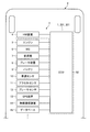
- FIG. 2 is a block diagram illustrating an example of a schematic configuration of the ECU according to the first embodiment.
- FIG. 3 is a flowchart illustrating an example of control by the ECU according to the first embodiment.
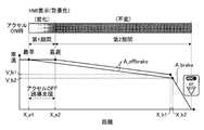
- FIG. 4 is a schematic diagram illustrating an example of a relationship between a remaining distance to a stop position and a vehicle speed and a support mode in the vehicle control system according to the first embodiment.
- FIG. 5 is a schematic diagram illustrating an example of a support display mode by the HMI device according to the first embodiment.
- FIG. 6 is a flowchart illustrating an example of control by the ECU according to the second embodiment.
- FIG. 1 is a schematic configuration diagram illustrating a vehicle control system according to the first embodiment.
- FIG. 2 is a block diagram illustrating an example of a schematic configuration of the ECU according to the first embodiment.
- FIG. 3 is a flowchart illustrating an example of
- FIG. 7 is a schematic diagram illustrating an example of the relationship between the remaining distance to the stop position and the vehicle speed and the support mode in the vehicle control system according to the second embodiment.
- FIG. 8 is a flowchart illustrating an example of control by the ECU according to the third embodiment.
- FIG. 9 is a schematic diagram illustrating an example of the relationship between the remaining distance to the stop position and the vehicle speed and the support mode in the vehicle control system according to the third embodiment.
- FIG. 1 is a schematic configuration diagram illustrating a vehicle control system according to the first embodiment
- FIG. 2 is a block diagram illustrating an example of a schematic configuration of an ECU according to the first embodiment
- FIG. 3 is a control by the ECU according to the first embodiment
- FIG. 4 is a schematic diagram showing an example of the relationship between the remaining distance to the stop position and the vehicle speed and the vehicle speed in the vehicle control system according to the first embodiment
- FIG. It is a schematic diagram showing an example of the support display mode by the HMI device.
- the driving support device 1 of this embodiment is applied to a vehicle control system 3 mounted on a vehicle 2 as shown in FIG.
- the driving assistance device 1 includes an HMI (Human Machine Interface) device (hereinafter also referred to as “HMI”) 4 as an assistance device, and an ECU (Electronic Control Unit) 50.
- HMI Human Machine Interface
- ECU Electronic Control Unit
- the driving assistance apparatus 1 supports the driving
- the vehicle control system 3 to which the driving support device 1 of the present embodiment is applied is a prefetch information eco driving support system that utilizes so-called prefetch information.
- the vehicle control system 3 uses the look-ahead information to support the driver's eco-driving (eco-driving) by assisting the driver to encourage the driver to drive with a high fuel efficiency improvement effect. To do.
- the vehicle control system 3 is a system configured to suppress fuel consumption and improve fuel efficiency.
- the driving support device 1 typically outputs driving support information and guides and supports the operation by the driver for the purpose of supporting eco-driving by the driver.
- the vehicle control system 3 of the present embodiment is also a so-called hybrid system in which the engine 5 and the MG 6 are combined and used as a driving source for driving for driving the driving wheels of the vehicle 2 to rotate. That is, the vehicle 2 is a hybrid vehicle provided with the MG 6 in addition to the engine 5 as a travel drive source. While the vehicle 2 operates the engine 5 in the most efficient state as much as possible, the MG 6 that is a rotating electrical machine compensates for excess and deficiency of power and engine braking force, and further regenerates energy during deceleration, thereby reducing fuel consumption. It is comprised so that improvement of may be aimed at.
- the vehicle control system 3 is described as being a hybrid system including the engine 5 and the MG 6 as a driving source for traveling, but is not limited thereto.
- the vehicle control system 3 may be a system that includes the engine 5 as a travel drive source but does not include the MG 6, or may include a system that includes the MG 6 as a travel drive source but does not include the engine 5.
- the vehicle 2 may be a so-called conveyor vehicle or an EV vehicle (electric vehicle).
- the vehicle control system 3 includes an HMI device 4, an engine 5 as an internal combustion engine, a motor generator (hereinafter sometimes referred to as “MG”) 6 as an electric motor, a transmission 7, a brake device 8, a battery. 9 etc. are comprised. Further, the vehicle control system 3 includes a vehicle speed sensor 10, an accelerator sensor 11, a brake sensor 12, a GPS (Global Positioning System) device (hereinafter sometimes referred to as “GPS”) 13, and a wireless communication device 14. , A database (hereinafter sometimes referred to as “DB”) 15 and the like.
- DB Global Positioning System
- the HMI device 4 is a support device that can output driving support information, which is information that supports driving of the vehicle 2, and is a device that provides driving support information to the driver.
- the HMI device 4 is an in-vehicle device and includes, for example, a display device (visual information display device), a speaker (sound output device), and the like provided in the vehicle interior of the vehicle 2.
- a display device visual information display device
- a speaker sound output device
- the HMI device 4 provides information by voice information, visual information (graphic information, character information), etc. so as to realize improvement in fuel consumption, and guides the driving operation of the driver.
- the HMI device 4 supports the realization of the target value by the driving operation of the driver by providing such information.
- the HMI device 4 is electrically connected to the ECU 50 and controlled by the ECU 50.
- the HMI device 4 may include a haptic information output device that outputs haptic information such as handle vibration, seat vibration, pedal reaction force, and the like.
- the vehicle control system 3 includes an engine 5, an MG 6, a transmission 7, a brake device 8, a battery 9, and the like as various actuators that realize traveling of the vehicle 2.
- the engine 5 applies a driving force to the wheels of the vehicle 2 in response to an acceleration request operation by the driver, for example, an accelerator pedal depression operation.
- the engine 5 consumes fuel as driving power to be applied to the drive wheels of the vehicle 2 and generates engine torque as engine torque.
- the engine 5 is a heat engine that outputs thermal energy generated by burning fuel in the form of mechanical energy such as torque, and examples thereof include a gasoline engine, a diesel engine, and an LPG engine.
- the engine 5 includes, for example, a fuel injection device, an ignition device, a throttle valve device, and the like (not shown). These devices are electrically connected to the ECU 50 and controlled by the ECU 50.
- the output torque of the engine 5 is controlled by the ECU 50.
- the power generated by the engine 5 may be used for power generation in the MG 6.
- MG6 is for applying a driving force to the wheels of the vehicle 2 in response to an acceleration request operation by the driver, for example, an accelerator pedal depression operation.
- the MG 6 converts electric energy into mechanical power as driving power to be applied to the driving wheels of the vehicle 2 to generate motor torque.
- MG6 is what is called a rotary electric machine provided with the stator which is a stator, and the rotor which is a rotor.
- the MG 6 is an electric motor that converts electric energy into mechanical power and outputs it, and also a generator that converts mechanical power into electric energy and recovers it.
- the MG 6 is driven by supplying electric power, functions as an electric motor that converts electric energy into mechanical energy and outputs it (power running function), and functions as a generator that converts mechanical energy into electric energy (regenerative function).
- the MG 6 is electrically connected to the ECU 50 through an inverter or the like that converts direct current and alternating current, and is controlled by the ECU 50.
- the output torque and power generation amount of the MG 6 are controlled by the ECU 50 via an inverter.
- the transmission 7 is a power transmission device that shifts the rotational output of the engine 5 and the MG 6 and transmits it to the drive wheel side of the vehicle 2.
- the transmission 7 may be a so-called manual transmission (MT), a stepped automatic transmission (AT), a continuously variable automatic transmission (CVT), a multimode manual transmission (MMT), a sequential manual transmission (SMT). ), A so-called automatic transmission such as a dual clutch transmission (DCT).
- MT manual transmission
- AT continuously variable automatic transmission
- MMT multimode manual transmission
- SMT sequential manual transmission
- DCT dual clutch transmission
- the brake device 8 applies a braking force to the wheels of the vehicle 2 in response to a braking request operation by the driver, for example, a depression operation of a brake pedal.
- the brake device 8 applies a braking force to a wheel rotatably supported on the vehicle body of the vehicle 2 by generating a predetermined frictional force (frictional resistance force) between frictional elements such as a brake pad and a brake disk, for example. .
- the brake device 8 can brake the vehicle 2 by generating a braking force on the contact surface with the road surface of the wheel of the vehicle 2.
- the brake device 8 is controlled by the ECU 50 with a brake actuator or the like electrically connected to the ECU 50.
- the battery 9 is a power storage device capable of storing electric power (electric storage) and discharging the stored electric power.
- the battery 9 is electrically connected to the ECU 50 and outputs signals related to various information to the ECU 50.
- the MG 6 When the MG 6 functions as an electric motor, the electric power stored in the battery 9 is supplied via an inverter, and the supplied electric power is converted into driving power for the vehicle 2 and output. Further, when the MG 6 functions as a generator, the MG 6 is driven by input power to generate power, and the generated power is charged to the battery 9 via an inverter. At this time, the MG 6 can brake the rotation of the rotor (regenerative braking) by the rotational resistance generated in the rotor. As a result, at the time of regenerative braking, the MG 6 can generate a motor regenerative torque that is a negative motor torque to the rotor by regenerating electric power, and as a result, can apply a braking force to the drive wheels of the vehicle 2. .
- the vehicle control system 3 mechanical power is input to the MG 6 from the drive wheel of the vehicle 2, and the MG 6 generates electric power by regeneration, whereby the kinetic energy of the vehicle 2 can be recovered as electric energy. .
- the vehicle control system 3 can perform regenerative braking by MG6 by transmitting the mechanical power (negative motor torque) which arises in the rotor of MG6 in connection with this to a driving wheel.
- the regeneration amount (power generation amount) by the MG 6 when the regeneration amount (power generation amount) by the MG 6 is relatively small, the generated braking force is relatively small, and the deceleration acting on the vehicle 2 is relatively small.
- the regeneration amount (power generation amount) by the MG 6 when the regeneration amount (power generation amount) by the MG 6 is relatively increased, the generated braking force is relatively increased, and the deceleration acting on the vehicle 2 is relatively increased.
- the vehicle speed sensor 10, the accelerator sensor 11, and the brake sensor 12 detect the running state of the vehicle 2 and the input (driver input) to the vehicle 2 by the driver, that is, the state quantity and physical quantity related to the actual operation on the vehicle 2 by the driver. It is a state detection device.
- the vehicle speed sensor 10 detects the vehicle speed of the vehicle 2 (hereinafter sometimes referred to as “vehicle speed”).
- the accelerator sensor 11 detects an accelerator opening that is an operation amount (depression amount) of an accelerator pedal by a driver.
- the brake sensor 12 detects an operation amount (depression amount) of the brake pedal by the driver, for example, a master cylinder pressure.
- the vehicle speed sensor 10, the accelerator sensor 11 and the brake sensor 12 are electrically connected to the ECU 50 and output detection signals to the ECU 50.
- the GPS device 13 is a device that detects the current position of the vehicle 2.
- the GPS device 13 receives a GPS signal output from a GPS satellite, and measures and calculates GPS information (X coordinate; X, Y coordinate; Y) that is position information of the vehicle 2 based on the received GPS signal.
- the GPS device 13 is electrically connected to the ECU 50 and outputs a signal related to GPS information to the ECU 50.
- the wireless communication device 14 is a prefetch information acquisition device that acquires prefetch information related to the traveling of the vehicle 2 using wireless communication.
- the wireless communication device 14 is, for example, a road-to-vehicle communication device (roadside device) such as an optical beacon installed on the roadside, a vehicle-to-vehicle communication device mounted on another vehicle, VICS (Vehicle Information and Communication System: road traffic information communication).
- Pre-reading information is acquired using wireless communication from a device that exchanges information using a communication infrastructure such as the Internet via a center.
- the wireless communication device 14 acquires, for example, preceding vehicle information, subsequent vehicle information, signal information, construction / traffic regulation information, traffic jam information, emergency vehicle information, information on an accident history database, and the like as prefetch information.
- the signal information includes position information of a traffic signal ahead of the vehicle 2 in the traveling direction, signal cycle information such as a green signal, a yellow signal, and a red signal lighting cycle and signal change timing.
- the wireless communication device 14 is electrically connected to the ECU 50 and outputs a signal related to the prefetch information to the ECU 50.
- the database 15 stores various information.
- the database 15 stores map information including road information, various information and learning information obtained by actual traveling of the vehicle 2, prefetched information acquired by the wireless communication device 14, and the like.
- the road information includes road gradient information, road surface state information, road shape information, restricted vehicle speed information, road curvature (curve) information, temporary stop information, stop line position information, and the like.
- Information stored in the database 15 is appropriately referred to by the ECU 50, and necessary information is read out.
- this database 15 is illustrated as being mounted on the vehicle 2 here, the database 15 is not limited to this, and is provided in an information center outside the vehicle 2 and appropriately referred to by the ECU 50 via wireless communication or the like. The necessary information may be read out.
- the ECU 50 is a control unit that performs overall control of the vehicle control system 3 and is configured as an electronic circuit mainly composed of a known microcomputer including a CPU, a ROM, a RAM, and an interface, for example.
- the ECU 50 detects detection results detected by the vehicle speed sensor 10, the accelerator sensor 11, and the brake sensor 12, GPS information acquired by the GPS device 13, prefetched information acquired by the wireless communication device 14, various information stored in the database 15, An electric signal corresponding to a drive signal, a control command, or the like of each part is input.
- the ECU 50 controls the HMI device 4, the engine 5, the MG 6, the transmission 7, the brake device 8, the battery 9, and the like according to these input electric signals and the like.
- the ECU 50 executes drive control of the engine 5, drive control of the MG 6, shift control of the transmission 7, brake control of the brake device 8, and the like based on the accelerator opening, the vehicle speed, and the like. Further, the ECU 50 can realize various vehicle travels (travel modes) in the vehicle 2 by using the engine 5 and the MG 6 together or selectively depending on the driving state, for example.
- the ECU 50 can detect ON / OFF of an accelerator operation that is an acceleration request operation for the vehicle 2 by the driver based on a detection result by the accelerator sensor 11.
- the ECU 50 can detect ON / OFF of a brake operation, which is a brake request operation for the vehicle 2 by the driver, based on a detection result by the brake sensor 12, for example.
- the state where the accelerator operation by the driver is OFF is a state where the driver cancels the acceleration request operation for the vehicle 2
- the state where the accelerator operation by the driver is ON is the state where the driver performs the operation for the vehicle 2.
- the acceleration request operation is being performed.
- the state in which the brake operation by the driver is OFF is a state in which the driver releases the braking request operation for the vehicle 2
- the state in which the brake operation by the driver is ON is the state in which the driver is in the vehicle 2. This is a state in which a braking request operation is being performed on.
- the driving assistance apparatus 1 is comprised including the above-mentioned HMI apparatus 4 and ECU50.
- the ECU 50 controls the HMI device 4 according to the situation and outputs various driving support information, so that the driver is urged to drive with a high fuel efficiency improvement effect.
- the driving assistance device 1 is configured to provide driving recommendations recommended to the driver by the HMI device 4 outputting various driving assistance information in accordance with control by the ECU 50 based on the target running state quantity of the vehicle 2 that is running.
- Guidance support that encourages movements, typically driving movements with changes, is performed.
- the target travel state quantity is typically a target travel state quantity of the vehicle 2 at a predetermined point or timing in the traveling vehicle 2.
- the ECU 50 controls the HMI device 4 based on the target travel state quantity at the predetermined point or timing, and the HMI device 4 outputs driving support information, which is recommended to the driver.
- Driving assistance is performed so that the running state quantity of the vehicle 2 becomes the target running state quantity at a predetermined point and timing by providing assistance for prompting the driving action.
- the driving support device 1 does not set the timing for prompting the driver to perform the recommended driving operation, but gives the driver the driving timing recommended for the driver. In this way, driving support information is output. Thereby, the driving assistance device 1 realizes appropriate driving assistance that suppresses the uncomfortable feeling given to the driver in the driving assistance. Further, here, the driving support device 1 changes the mode for prompting the driver to perform the recommended driving operation according to the change in time. As a result, the driving support device 1 makes it easier for the driver to understand that the timing for prompting the recommended driving operation is widened, and makes the driver feel driving support by the driving support device 1 more easily. As a result, more appropriate driving assistance is realized.
- the ECU 50 controls the HMI device 4 and includes a first period from the earliest timing as the first support timing to the latest timing as the second support timing, and a second period after the latest timing.
- the mode of driving support information is varied.
- the HMI device 4 outputs the driving support information in the first mode in the first period from the earliest timing to the latest timing.
- the HMI device 4 outputs the driving support information in a second mode different from the first mode in the second period after the latest timing.
- the earliest timing and the latest timing are both timings determined based on the target travel state quantity, and the latest timing is the timing after the earliest timing in time series.
- the earliest timing is the earliest timing at which the driving state quantity of the vehicle 2 can become the target driving state quantity at a predetermined point by performing the driving operation recommended by the driver, and is also the support start timing by the driving support device 1.
- the latest timing is the latest timing at which the driving state quantity of the vehicle 2 can become the target driving state quantity at a predetermined point by performing the driving operation recommended by the driver.
- the traveling state amount becomes substantially the target traveling state amount at a predetermined point.
- the driving support device 1 outputs the driving support information by the HMI device 4 and prompts the recommended driving operation so that the driver performs the recommended driving operation in the first period from the earliest timing to the latest timing.
- driving assistance can be performed so that the travel state quantity of the vehicle 2 becomes the target travel state quantity at a predetermined point and timing.
- the ECU50 of this embodiment changes the aspect of driving assistance information with progress of time in the 1st period from the earliest timing to the latest timing. That is, the ECU 50 changes the mode of the driving support information as time elapses from the earliest timing that is the support start timing.
- the ECU 50 of the present embodiment fixes the mode of the driving support information in the second period after the latest timing. That is, the first mode of the driving support information in the first period is a mode in which the driving support information is changed as time passes.
- the second mode of the driving support information in the second period is a mode in which the driving support information is not changed over time.
- the target travel state quantity will be described as an example of a target brake operation start vehicle speed that is a recommended vehicle speed for which a driver's brake operation (braking request operation) is recommended.
- the recommended driving operation that the driving support device 1 provides guidance assistance to the driver will be described as an accelerator operation OFF operation (acceleration request operation canceling operation) by the driver as an example.
- the driving support device 1 outputs visual information as driving support information.
- the driving support device 1 is configured to display visual information as driving support information on a visual information display device such as a center meter, a head-up display (HUD), a windshield display, a liquid crystal display, or the like constituting the HMI device 4. explain.
- the vehicle speed becomes approximately the target brake operation start vehicle speed at a predetermined point.
- the first period from the earliest timing to the latest timing is an optimal accelerator operation OFF period.
- the driving support device 1 displays an image of driving support information on the HMI device 4 and prompts the accelerator operation to be turned OFF so that the driver performs the accelerator operation OFF operation in the first period from the earliest timing to the latest timing. Accelerator OFF guidance support is performed.
- the driving assistance apparatus 1 can perform driving assistance so that the vehicle speed of the vehicle 2 becomes the target brake operation start vehicle speed at a predetermined point and timing.
- the ECU 50 includes a first information calculation unit 51, a second information calculation unit 52, and a vehicle control unit 53.
- the first information calculation unit 51 and the second information calculation unit 52 are calculation units compatible with, for example, ITS (Intelligent Transport Systems), and are calculation units for performing infrastructure cooperation and NAVI cooperation.
- the vehicle control unit 53 is a control unit that controls each unit of the vehicle 2.
- the vehicle control unit 53 controls various actuators such as an engine control ECU, an MG control ECU, a transmission control ECU, a brake control ECU, and a battery control ECU via a CAN (Control Area Network) 54 constructed as an in-vehicle network. It is connected to the actuator ECU and sensors.
- the ECU 50 is not limited to this, and may be configured to include a NAVI device instead of the first information calculation unit 51, for example.
- the first information calculation unit 51 calculates a remaining distance from the vehicle 2 to a temporary stop or a curve ahead in the traveling direction based on static infrastructure information, for example, map information including road information.
- the first information calculation unit 51 learns the driver's normal driving behavior, performs driving behavior estimation based on this, and also learns and predicts the driver's deceleration stop behavior.
- the 1st information calculation part 51 also calculates the remaining distance from the vehicle 2 to the deceleration stop position ahead of a running direction.
- the deceleration stop position obtained by learning the driver's normal driving behavior is, for example, a position where the driver frequently decelerates and stops other than temporarily stop.
- the first information calculation unit 51 learns the driver's deceleration stop action based on various information obtained by actual traveling of the vehicle 2, that is, learns the deceleration stop position according to the driver. Good. For example, the first information calculation unit 51 calculates the habit and tendency of the driving operation from the normal driving of the driver based on various information obtained by actual driving of the vehicle 2 (for example, the attribute of the driver). ), A place (for example, a position where an operation was performed, etc.), a situation (for example, a time zone, etc.), etc. The first information calculation unit 51 learns, for example, a deceleration stop position where the driver frequently stops and decelerates and stops frequently by statistically processing the accelerator operation and the brake operation ON / OFF by the driver. To do. The first information calculation unit 51 stores the learned information in the database 15 as learning information.
- the first information calculation unit 51 is functionally conceptually configured to include a position rating unit 51a, a pause / curve information acquisition unit (hereinafter also referred to as a “stop / curve information acquisition unit”) 51b, and a subtractor 51c. And are provided.
- the position rating unit 51 a acquires GPS information via the GPS device 13 and acquires current position information of the vehicle (own vehicle) 2.
- the position evaluation unit 51a outputs the current position information to the pause / curve information acquisition unit 51b and the subtractor 51c.
- the stop / curve information acquisition unit 51b is based on the current position information input from the position evaluation unit 51a, and includes map information stored in the database 15, various information and learning information obtained by actual traveling of the vehicle 2.
- the target position information indicating the temporary stop, curve, or deceleration stop position in front of the traveling direction of the vehicle 2 is acquired.
- the stop / curve information acquisition unit 51b outputs the target position information to the subtractor 51c.
- the subtractor 51c is a temporary stop, curve, or deceleration stop position indicated by the position of the vehicle 2 indicated by the current position information input from the position evaluation unit 51a and the target position information input from the stop / curve information acquisition unit 51b.
- the remaining distance to the temporary stop, curve, or deceleration stop position is calculated.
- the subtractor 51 c outputs the remaining distance information indicating the remaining distance to the arbitrating unit 53 a of the vehicle control unit 53.
- the second information calculation unit 52 calculates the remaining distance from the vehicle 2 to the stop position by the red signal ahead of the traveling direction based on dynamic infrastructure information, for example, signal information.
- the second information calculation unit 52 is functionally conceptually provided with a position rating unit 52a, a signal information acquisition unit 52b, and a subtractor 52c.
- the position rating unit 52 a acquires GPS information via the GPS device 13 and acquires current position information of the vehicle (own vehicle) 2.
- the position rating unit 52a outputs the current position information to the subtracter 52c.
- the signal information acquisition unit 52b acquires signal information via the wireless communication device 14, and acquires target position information indicating a stop position by a red signal ahead of the traveling direction of the vehicle 2 based on the signal information.
- the signal information acquisition unit 52b outputs this target position information to the subtracter 52c.
- the subtractor 52c calculates the difference between the position of the vehicle 2 indicated by the current position information input from the position evaluation unit 52a and the stop position by the red signal indicated by the target position information input from the signal information acquisition unit 52b. The remaining distance to the stop position by the signal is calculated. The subtractor 52 c outputs the remaining distance information indicating the remaining distance to the arbitrating unit 53 a of the vehicle control unit 53.
- the vehicle control unit 53 includes a remaining distance to the temporary stop, curve, or deceleration stop position calculated by the first information calculation unit 51, a remaining distance to the stop position based on a red signal calculated by the second information calculation unit 52, a vehicle
- the braking / driving force of the HMI device 4 and the vehicle 2 is comprehensively controlled based on the vehicle speed Vx, the accelerator operation ON / OFF, the brake operation ON / OFF, and the like.
- the vehicle control unit 53 is conceptually provided with an arbitration unit 53a, a target calculation unit 53b, and a braking / driving force control unit 53c.
- the arbitration unit 53a arbitrates the remaining distance information to the temporary stop, curve, or deceleration stop position input from the subtractor 51c and the remaining distance information to the stop position by the red signal input from the subtractor 52c. Is.
- the arbitration unit 53a mediates the remaining distance information based on the accuracy of the remaining distance information, the magnitude relationship of the remaining distance, and the like, and outputs the arbitration result to the target calculation unit 53b.
- the target calculation unit 53b calculates the target travel state quantity based on the arbitration result of the remaining distance information input from the arbitration unit 53a, the vehicle speed Vx of the vehicle 2 input from the vehicle speed sensor 10 via the CAN 54, and the like. And the target calculating part 53b controls the HMI apparatus 4 based on this target driving
- FIG. 4 a case where driving assistance for a stop position by a temporary stop or a red signal is targeted is described, but driving assistance for a curve where a driver's braking operation is predicted is targeted. Is almost the same. However, in the case of driving assistance for a curve for which a brake operation by the driver is predicted, the brake operation by the driver may end in a state where the vehicle speed of the vehicle 2 is greater than 0, as in the example of FIG. Are different (the same applies to the following embodiments).
- the target calculation unit 53b calculates the earliest timing and the latest timing based on the target travel state quantity and the accelerator OFF deceleration.
- the accelerator OFF deceleration corresponds to the deceleration of the vehicle 2 in a state where the accelerator operation and the brake operation are OFF (a state where the acceleration request operation and the brake request operation for the vehicle 2 are released).
- the target travel state quantity is the target brake operation start vehicle speed at which the driver is recommended to perform the brake operation
- the target calculation unit 53b has a different target from the equivalent accelerator OFF deceleration. The earliest timing and the latest timing are calculated based on the brake operation start vehicle speed.
- the target calculation unit 53b first sets a target brake operation start upper limit vehicle speed V_b1 and a target brake operation start upper limit vehicle speed V_b1 as different target brake operation start vehicle speeds based on the current vehicle speed (entrance vehicle speed) V_now of the vehicle 2.
- the brake operation start lower limit vehicle speed V_b2 is calculated (ST1).
- the target calculation unit 53b multiplies the vehicle speed V_now by a predetermined upper limit vehicle speed coefficient to calculate the target brake operation start upper limit vehicle speed V_b1.
- the target calculation unit 53b calculates a target brake operation start lower limit vehicle speed V_b2 by multiplying the vehicle speed V_now by a predetermined lower limit vehicle speed coefficient smaller than the upper limit vehicle speed coefficient.
- the upper limit vehicle speed coefficient is such that, for example, the target brake operation start upper limit vehicle speed V_b1 does not cause the driver of the vehicle 2 and the driver of the following vehicle to feel that it is a sudden brake when the brake operation is turned ON. It is set to become the speed of.
- the lower limit vehicle speed coefficient is, for example, that the target brake operation start lower limit vehicle speed V_b2 is from the time when the accelerator operation is turned OFF until the time when the brake operation is turned ON.
- the speed of the vehicle 2 is set so as not to give stress due to the vehicle speed being too slow and to reach the stop position.
- the target calculation unit 53b is the earliest target brake operation start as a predetermined point based on the target brake operation start upper limit vehicle speed V_b1, the target brake operation start lower limit vehicle speed V_b2, and the preset target brake deceleration A_brake.
- the position X_b1 and the target brake operation start latest position X_b2 are calculated (ST2).
- the target brake deceleration A_brake is fixed in advance according to a deceleration that does not cause the driver to feel that the brake is sudden and does not give a sense of incongruity when the driver turns on the brake operation. Set as a value.
- the target brake deceleration A_break is set to a deceleration with a slight margin added to the regeneration upper limit deceleration that can be efficiently regenerated by the MG 6. More preferably.
- the target brake deceleration A_break is set according to the deceleration that can satisfy the deceleration requested by the driver according to the brake operation by the regenerative braking by the MG 6.
- the vehicle control system 3 which is a hybrid system, determines that the deceleration required in accordance with the driver's brake operation is equal to or less than the target brake deceleration, without relying on friction braking by the brake device 8, MG6.
- the vehicle 2 can be stopped at the stop position by regenerative braking.
- the vehicle control system 3 can efficiently recover the kinetic energy of the vehicle 2 as electric energy by brake regeneration according to the driver's brake operation without consuming it as heat energy by friction braking.
- the fuel efficiency improvement effect can be expected.
- the target calculation unit 53b uses the stop position corresponding to the remaining distance adjusted by the arbitration unit 53a as a reference position, and based on the target brake operation start upper limit vehicle speed V_b1 and the target brake deceleration A_break, the target brake operation start earliest position X_b1. Is calculated. That is, the target calculation unit 53b starts the brake operation that can stop the vehicle 2 at the stop position when the vehicle 2 traveling at the target brake operation start upper limit vehicle speed V_b1 is decelerated at the target brake deceleration A_brake by the brake operation. The position is calculated backward, and this is set as the earliest position X_b1 for starting the target brake operation.
- the target calculation unit 53b starts the target brake operation based on the target brake operation start lower limit vehicle speed V_b2 and the target brake deceleration A_brake, with the stop position corresponding to the remaining distance adjusted by the arbitration unit 53a as a reference position.
- the latest position X_b2 is calculated. That is, the target calculation unit 53b starts the brake operation that can stop the vehicle 2 at the stop position when the vehicle 2 traveling at the target brake operation start lower limit vehicle speed V_b2 is decelerated at the target brake deceleration A_brake by the brake operation.
- the position is calculated backward, and this is set as the target brake operation start latest position X_b2.
- the combination of the earliest target brake operation start position X_b1 as the predetermined point and the target brake operation start upper limit vehicle speed V_b1 as the target travel state quantity is stopped at the optimum target brake deceleration A_break when the driver performs the brake operation.
- the combination of the target brake operation start latest position X_b2 as the predetermined point and the target brake operation start lower limit vehicle speed V_b2 as the target travel state quantity is an optimal target brake deceleration A_brake when the driver performs the brake operation. This corresponds to a combination of the latest brake operation start position that can be approached to the stop position and the brake operation start vehicle speed.
- the vehicle 2 is located in a range from the target brake operation start earliest position X_b1 to the target brake operation start latest position X_b2, and the vehicle speed is from the target brake operation start upper limit vehicle speed V_b1 to the target brake operation start lower limit vehicle speed V_b2.
- the vehicle 2 can be stopped at the stop position at an optimum target brake deceleration A_brake or less.
- the vehicle support speed is changed from the target brake operation start upper limit vehicle speed V_b1 to the target brake operation.
- the driver's accelerator operation OFF operation is guided and supported.
- the driving support device 1 causes the deceleration required in accordance with the brake operation to be equal to or less than the optimum target brake deceleration A_brake. Therefore, it is possible to guide appropriately.
- the target calculation unit 53b based on the target brake operation start earliest position X_b1 and the target brake operation start latest position X_b2, and the predetermined accelerator OFF deceleration A_offbreake set in advance, the accelerator OFF induction earliest position X_a1 and The latest accelerator OFF guidance position X_a2 is calculated (ST3).
- Accelerator OFF deceleration A_offbrake is the deceleration of the vehicle 2 in a state where the accelerator operation and the brake operation are OFF.
- the accelerator OFF deceleration A_offbrake is, for example, the engine brake torque due to the rotational resistance of the engine 5, the TM brake torque due to the rotational resistance of the transmission 7, and the motor regeneration torque corresponding to the regeneration amount in the MG 6 in the hybrid system as in this embodiment. Based on the above, it is set in advance as a fixed value.
- the target calculation unit 53b calculates the accelerator OFF induction earliest position X_a1 based on the accelerator OFF deceleration A_offbrake and the target brake operation start lower limit vehicle speed V_b2 with the target brake operation start latest position X_b2 as a reference position. That is, when the vehicle 2 decelerates at the accelerator OFF deceleration A_offbrake, the target calculation unit 53b can make the vehicle speed of the vehicle 2 the target brake operation start lower limit vehicle speed V_b2 at the target brake operation start latest position X_b2. Is calculated in reverse, and this is set as the accelerator OFF induction earliest position X_a1.
- the target calculation unit 53b calculates the accelerator OFF induction earliest position X_a1 based on the accelerator OFF deceleration A_offbrake and the target brake operation start upper limit vehicle speed V_b1 with the target brake operation start earliest position X_b1 as a reference position. That is, when the vehicle 2 decelerates at the accelerator OFF deceleration A_offbrake, the target calculation unit 53b can perform the accelerator operation that can make the vehicle speed of the vehicle 2 the target brake operation start upper limit vehicle speed V_b1 at the earliest target brake operation start position X_b1. The OFF position is calculated backward, and this is set as the accelerator OFF induction latest delay position X_a2.
- the target calculation unit 53b relates to accelerator OFF guidance support in the first period from the earliest timing when the vehicle 2 reaches the accelerator OFF guidance earliest position X_a1 to the latest timing when the vehicle 2 reaches the accelerator OFF guidance latest position X_a2 at the current vehicle speed.
- the driving support information is output to the HMI device 4.
- the HMI device 4 displays the HMI related to the accelerator OFF guidance support as the driving support information (ST4), ends the current control cycle, and shifts to the next control cycle.
- the target calculation unit 53b of the present embodiment varies the display mode of the driving support information in the first period from the earliest timing to the latest timing calculated as described above and in the second period after the latest timing. .
- the target calculation unit 53b changes the mode of driving support information from the earliest timing to the latest timing and the mode of driving support information after the latest timing. That is, the target calculation unit 53b changes the display mode of the driving support information before and after the latest timing with the latest timing as a boundary.
- the first mode of the driving support information in the first period is a mode in which the driving support information is changed and displayed with the passage of time. That is, the first period from the earliest timing to the latest timing is a display fluctuation period in the driving assistance of the HMI device 4.
- the target calculation unit 53b gradually changes the display mode of the driving support information in the HMI device 4 as it approaches the latest timing from the earliest timing.
- the target calculation unit 53b gradually changes the background color 55 of the car icon of the center meter constituting the HMI device 4 as shown in the upper part of FIG. 4 and FIG.
- the target computing unit 53b gradually changes the background color 55 from a colorless state to a dark orange color or gradually expands the range of the background color 55 as it approaches the earliest timing from the earliest timing. .
- the target calculation unit 53b realizes the first display mode of the driving support information in the HMI device 4 in the first period from the earliest timing to the latest timing.
- the driving assistance device 1 can urge the driver to turn off the accelerator operation in a first period from the earliest timing to the latest timing.
- the second mode of the driving support information in the second period is a display mode in which the driving support information is not changed over time. That is, the second period after the latest timing is a fixed display period in the driving assistance of the HMI device 4.
- the target calculation unit 53b keeps the background color 55 unchanged with a dark orange color. In this way, the target calculation unit 53b realizes the second display mode of the driving support information in the HMI device 4 in the second period after the latest timing. Thereby, the driving assistance device 1 can prompt the driver to turn off the accelerator operation with a stronger expression in the second period after the latest timing.
- the driving support device 1 can guide and assist the driver's accelerator operation OFF operation in the first period from the earliest timing to the latest timing.
- the vehicle speed is changed from the target brake operation start upper limit vehicle speed V_b1 to the target brake operation. It is possible to guide and assist the timing of the driver's accelerator operation OFF operation so that the vehicle speed falls within the range up to the start lower limit vehicle speed V_b2.
- the driving support device 1 is set so that the deceleration required in accordance with the brake operation is equal to or less than the optimal target brake deceleration A_brake. Can be guided appropriately.
- the driving assistance device 1 can assist the driver so that the driver does not feel that the brake is sudden when the brake operation is turned ON. An effect can also be realized.
- the driving assistance device 1 of this embodiment outputs the driving assistance information so as to give a range to the timing for prompting the driver to perform the recommended driving operation, and thus appropriately suppresses the uncomfortable feeling given to the driver.
- Driving assistance can be realized. That is, the driving support device 1 displays the driving support information in such a manner that the driver does not display the driving support information in a wide range, instead of pinpointing the timing for prompting the driver to turn off the accelerator operation. Driving assistance can be performed in consideration of the reaction time until the accelerator operation is actually turned off. The reaction time until the accelerator operation is actually turned OFF varies among drivers and varies depending on the surrounding traffic environment such as driving load. However, the driving assistance device 1 can appropriately perform driving assistance regardless of variations in the reaction time and the like by providing driving assistance with a wide timing for prompting the accelerator operation to be turned off.
- the driving support device 1 provides driving support with a wide timing for prompting the accelerator operation OFF operation, so that even if the actual accelerator operation OFF operation timing varies, the driving support device 1 is within a previously predicted range. The influence on subsequent operation and control can be minimized.
- the driving support device 1 provides guidance assistance for the accelerator operation OFF operation within the first period from the earliest timing to the latest timing, so that, for example, the vehicle speed of the vehicle 2 before the stop position is too high and the brake operation is performed. It is possible to suppress sudden braking when the ON operation is performed.
- the driving support device 1 provides guidance assistance for the accelerator operation OFF operation within the first period from the earliest timing to the latest timing, for example, the vehicle speed of the vehicle 2 before the stop position is too low. Moreover, it can suppress giving a stress with respect to the driver of the vehicle 2 and the driver of the succeeding vehicle.
- the driving support device 1 prompts the driver to turn off the accelerator operation by changing the support mode when prompting the driver to turn off the accelerator operation as time elapses from the earliest timing. This makes it easier for the driver to understand that the timing is wide. As a result, the driving support device 1 can make the driver feel the driving support by the driving support device 1 easily, thereby realizing more appropriate driving support.
- the braking / driving force control unit 53c performs braking / driving force control when the driver actually turns off the accelerator operation in the first period from the earliest timing to the latest timing.
- the deceleration is adjusted so as to be the prescribed accelerator OFF deceleration A_offbrake.
- the braking / driving force control unit 53c performs engine braking by MG6 in addition to normal engine braking or the like so that the deceleration becomes the prescribed accelerator OFF deceleration A_offbrake.
- Regenerative emblem expansion control that performs regeneration is executed.
- the engine brake regeneration by this regeneration emblem expansion control has a relatively high regeneration efficiency because there is less influence of the amount of heat generated during regeneration compared to the brake regeneration according to the driver's brake operation ON operation described above. Tend to be. Therefore, the vehicle control system 3 ensures a relatively long period of time for executing the regeneration emblem expansion control by guiding and assisting the driver's accelerator operation OFF operation at an appropriate timing by the driving support device 1. Therefore, a higher fuel efficiency improvement effect can be expected.
- the target calculation unit 53b performs the accelerator operation OFF operation together with the regeneration emblem expansion control.
- Driving support information indicating that the operation has been properly performed is output to the HMI device 4.
- the HMI device 4 changes the background color 55 to green or the like, thereby displaying an HMI indicating that the accelerator is appropriately turned off as driving support information.
- the driving assistance device 1 can inform the driver that traveling that contributes to improvement in fuel efficiency is possible.
- the vehicle control system 3 can obtain a fuel efficiency improvement effect even when the driver's accelerator operation OFF operation is actually performed in the second period after the latest timing.
- the vehicle control system 3 is configured such that, for example, the deceleration required in accordance with the driver's brake operation becomes larger than the target brake deceleration A_brake, so that the friction braking by the brake device 8 is performed in addition to the regenerative braking by the MG 6. May also be used to stop the vehicle 2 at the stop position.
- the vehicle control system 3 slightly reduces the recovery efficiency of the kinetic energy of the vehicle 2, but the remaining kinetic energy of the vehicle 2 Can be recovered as electric energy by brake regeneration, so that a predetermined fuel efficiency improvement effect can be ensured.
- the HMI device 4 that can output driving support information that supports driving of the vehicle 2 based on the target brake operation start vehicle speed of the vehicle 2, and the HMI device 4
- the mode of the driving support information is variable depending on the period from the earliest timing based on the target brake operation start vehicle speed to the latest timing after the earliest timing and the period after the latest timing.
- the ECU 50 is provided.
- the HMI device 4 that can output driving support information that supports driving of the vehicle 2 based on the target brake operation start vehicle speed of the vehicle 2, and the HMI device 4 And an ECU 50 that changes the mode of the driving support information with the passage of time from the earliest timing based on the target brake operation start vehicle speed.
- the driving support device 1 can support the driving of the vehicle 2 in an easy-to-understand manner at an appropriate timing, the driving support device 1 can appropriately support driving. Drive) appropriately, thereby suppressing fuel consumption and improving fuel efficiency.
- the driving support device 1 has been described on the assumption that the vehicle 2 is a hybrid vehicle.
- the driving support device 1 is not limited to this, and even if it is a conveyor vehicle or an EV vehicle, it can appropriately support driving. it can.
- FIG. 6 is a flowchart showing an example of control by the ECU according to the second embodiment
- FIG. 7 is an example of the relationship between the remaining distance to the stop position and the vehicle speed in the vehicle control system according to the second embodiment and the support mode. It is a schematic diagram to represent.
- the driving support apparatus according to the second embodiment is different from the first embodiment in that the deceleration of the vehicle in a state where the acceleration request operation and the brake request operation for the vehicle are released is changed.
- the overlapping description is abbreviate
- each structure of the driving assistance device which concerns on Embodiment 2, FIG.1, FIG.2 etc. are referred (following, the same).
- the driving support device 201 can change the deceleration of the vehicle 2 in a state where the accelerator operation and the brake operation are OFF, that is, the accelerator OFF deceleration A_offbrake.
- the accelerator OFF deceleration A_offbrake is, for example, the engine brake torque due to the rotational resistance of the engine 5, the TM brake torque due to the rotational resistance of the transmission 7, and the regeneration amount in the MG 6 in the hybrid system as in this embodiment. It is determined based on the corresponding motor regeneration torque or the like.
- the driving assistance device 201 can change the accelerator OFF deceleration A_offbrake, for example, by changing the gear ratio (shift speed) of the transmission 7 or the regeneration amount in the MG 6.
- the driving support device 201 changes the accelerator OFF deceleration A_offbrake according to the remaining distance to the stop position at the timing of the actual accelerator operation OFF operation by the driver.
- the driving support device 201 can detect a combination of the actual brake operation start position and the brake operation start vehicle speed if the actual accelerator operation OFF operation is performed within the first period from the earliest timing to the latest timing. However, it can be made substantially the same regardless of the OFF operation timing of the accelerator operation.
- the driving support device 201 adjusts the accelerator OFF deceleration A_offbrake to adjust the brake operation even if the actual accelerator operation OFF operation timing varies within the first period from the earliest timing to the latest timing.
- the start position and the brake operation start vehicle speed can be adjusted to an appropriate combination.
- the driving support device 201 of the present embodiment is used as the deceleration control device as well as the ECU 50 as the support control device.
- the ECU 50 changes the accelerator OFF deceleration A_offbrake stepwise by changing the gear ratio (shift stage) of the transmission 7 or the regeneration amount in the MG 6 stepwise.
- the ECU 50 may change the accelerator OFF deceleration A_offbrake into two stages of an accelerator OFFD range deceleration A_offbrakeD as the first deceleration and an accelerator OFFB range deceleration A_offbrakeB as the second deceleration. it can.
- the accelerator OFFD range deceleration A_offbrakeD corresponds to the accelerator OFF deceleration when a so-called drive range is selected as the shift range.
- the accelerator OFFB range deceleration A_offbreakB corresponds to the accelerator OFF deceleration when a so-called brake range is selected as the shift range, and is a deceleration having a relatively large absolute value compared to the accelerator OFFD range deceleration A_offbrakeD. .
- the ECU 50 changes the timing for switching between the accelerator OFFD range deceleration A_offbreakD and the accelerator OFFB range deceleration A_offbreakB according to the timing of the actual accelerator operation OFF operation by the driver.
- the target calculation unit 53b calculates the earliest timing and the latest timing based on the target travel state quantity and the accelerator OFF deceleration. Further, here, as described above, the target travel state quantity is the target brake operation start vehicle speed at which the brake operation by the driver is recommended, and the target calculation unit 53b of the present embodiment starts the equivalent target brake operation start. The earliest timing and the latest timing are calculated based on the vehicle speed and the different accelerator OFF deceleration.
- the target calculation unit 53b first calculates a target brake operation start vehicle speed V_b based on the current vehicle speed (incoming vehicle speed) V_now of the vehicle 2 (ST21).
- the target calculation unit 53b calculates a target brake operation start vehicle speed V_b by multiplying the vehicle speed V_now by a predetermined vehicle speed coefficient.
- the vehicle speed coefficient is, for example, a speed at which the target brake operation start vehicle speed V_b does not cause the driver of the vehicle 2 and the driver of the following vehicle to feel sudden braking when the brake operation is turned ON.
- the speed is set so that the vehicle 2 can reach the stop position without causing stress due to the vehicle speed being too slow.
- the target calculation unit 53b calculates a target brake operation start position X_b as a predetermined point based on the target brake operation start vehicle speed V_b and a preset target brake deceleration A_brake (ST22).
- the target calculation unit 53b calculates the target brake operation start position X_b based on the target brake operation start vehicle speed V_b and the target brake deceleration A_break using the stop position according to the remaining distance adjusted by the arbitration unit 53a as a reference position. To do. That is, the target calculation unit 53b can stop the vehicle 2 at the stop position when the vehicle 2 traveling at the target brake operation start vehicle speed V_b decelerates at the target brake deceleration A_brake by the brake operation. Is calculated as a target brake operation start position X_b.
- the combination of the target brake operation start position X_b as the predetermined point and the target brake operation start vehicle speed V_b as the target travel state quantity is set to the stop position at the optimal target brake deceleration A_break when the driver performs the brake operation. This corresponds to a combination of a brake operation start position and a brake operation start vehicle speed that can be approached.
- the target calculation unit 53b based on the target brake operation start position X_b, and the accelerator OFFD range deceleration A_offbrakeD and the accelerator OFFB range deceleration A_offbreakB set in advance, the accelerator OFF induction earliest position X_a1 and the accelerator OFF induction The latest position X_a2 is calculated (ST23).
- the target calculation unit 53b calculates the accelerator OFF induction earliest position X_a1 based on the accelerator OFFD range deceleration A_offbrakeD and the target brake operation start vehicle speed V_b with the target brake operation start position X_b as a reference position. That is, when the vehicle 2 decelerates at the accelerator OFFD range deceleration A_offbrakeD, the target calculation unit 53b can turn off the accelerator operation that can set the vehicle speed of the vehicle 2 to the target brake operation start vehicle speed V_b at the target brake operation start position X_b. The position is calculated backward, and this is set as the accelerator OFF guidance earliest position X_a1.
- the target calculation unit 53b calculates the accelerator OFF induction latest position X_a2 based on the accelerator OFFB range deceleration A_offbrakeB and the target brake operation start vehicle speed V_b with the target brake operation start position X_b as a reference position. That is, when the vehicle 2 decelerates at the accelerator OFFB range deceleration A_offbrakeB, the target calculation unit 53b can turn off the accelerator operation that can set the vehicle speed of the vehicle 2 to the target brake operation start vehicle speed V_b at the target brake operation start position X_b. The position is calculated backward, and this is set as the accelerator-off induction latest position X_a2.
- the target calculation unit 53b performs driving related to accelerator OFF guidance support in the first period from the earliest timing when the vehicle 2 reaches the accelerator OFF guidance earliest position X_a1 to the latest timing when the vehicle 2 reaches the accelerator OFF guidance latest position X_a2 at the current vehicle speed.
- Support information is output to the HMI device 4.
- the HMI apparatus 4 displays HMI regarding an accelerator OFF guidance assistance as driving assistance information (ST24).
- the target calculation unit 53b varies the display mode of the driving support information between the first period from the earliest timing to the latest timing calculated as described above and the second period after the latest timing.
- the first mode of the driving support information in the first period is a mode in which the driving support information is changed and displayed over time.
- the second mode of the driving support information in the second period is a display mode in which the driving support information is not changed over time. Therefore, the driving support device 201 can guide and assist the driver's accelerator operation OFF operation in the first period from the earliest timing to the latest timing.
- the braking / driving force control unit 53c performs braking / driving force control when the driver actually turns off the accelerator operation in the first period from the earliest timing to the latest timing.
- the deceleration is adjusted so as to be the prescribed accelerator OFFD range deceleration A_offbrakeD.
- the braking / driving force control unit 53c executes regenerative emblem expansion control for performing engine brake regeneration by the MG 6 in addition to normal engine braking and the like.
- the braking / driving force control unit 53c of the present embodiment determines the remaining vehicle speed V_now of the current vehicle 2 and the remaining distance L from the current position X_r to the stop position at the timing when the driver's accelerator operation is actually turned off. Based on the above, the timing for switching the accelerator OFF deceleration is calculated. For example, the braking / driving force control unit 53c switches the accelerator OFF deceleration from the accelerator OFFD range deceleration A_offbrakeD to the accelerator OFFB range deceleration A_offbrakeB at the timing when the inequality sign of the following formula (1) is established.
- the braking / driving force control unit 53c adjusts so that the actual deceleration of the vehicle 2 becomes the accelerator OFFB range deceleration A_offbreakB (ST25), ends the current control cycle, and shifts to the next control cycle. .
- [V_now] represents the current vehicle speed of the vehicle 2 at which the driver performs the accelerator operation OFF operation.
- V_b represents the target brake operation start vehicle speed.
- A_offbreak B] represents the acceleration OFFB range deceleration.
- L represents the remaining distance from the current position to the stop position at the timing when the driver's accelerator operation is actually turned OFF.
- X_b] represents the target brake operation start position.
- the driving support device 201 configured as described above displays the driving support information in the first mode in the first period from the earliest timing to the latest timing, so that the vehicle 2 reaches the target brake operation start position X_b. In this case, it is possible to guide and assist the timing of the driver's accelerator operation OFF operation so that the vehicle speed becomes the target brake operation start vehicle speed V_b. As a result, when the driver actually performs the brake operation in order to stop at the stop position, the driving support device 201 causes the deceleration required in accordance with the brake operation to be equal to or less than the optimum target brake deceleration A_break. Moreover, since it can guide
- the driving assistance apparatus 201 determines the earliest timing and the latest timing based on the equivalent target brake operation start vehicle speed and the different accelerator OFF deceleration, the first period from the earliest timing to the latest timing is determined. It can be set as a relatively long period. Therefore, the driving assistance device 201 can suppress the first period from the earliest timing to the latest timing from being too short, and can more appropriately perform driving assistance for the driver.
- the driving support device 201 adjusts the accelerator OFF deceleration to adjust the actual brake operation even if the actual accelerator operation OFF operation timing varies within the first period from the earliest timing to the latest timing.
- the start position and the brake operation start vehicle speed can be adjusted to an appropriate combination.
- the driving support device 201 determines that the combination of the actual brake operation start position and the brake operation start vehicle speed is obtained when the actual accelerator operation OFF operation is performed within the first period from the earliest timing to the latest timing.
- the accelerator operation can be made substantially the same regardless of the OFF operation timing.
- the driving support device 201 detects the combination of the target brake operation start position and the target brake operation start vehicle speed that can approach the stop position with the optimum target brake deceleration A_brake when the driver performs the brake operation.
- the driving support device 201 detects the combination of the target brake operation start position and the target brake operation start vehicle speed that can approach the stop position with the optimum target brake deceleration A_brake when the driver performs the brake operation.
- variation in the combination of the actual brake operation start position and the brake operation start vehicle speed can be suppressed.
- the driving support device 201 can support the driving of the vehicle 2 in an easily understandable manner at an appropriate timing, the driving supporting device 201 can appropriately support driving, for example, driving It is possible to appropriately support the eco-driving (eco-driving) by the person, thereby suppressing fuel consumption and improving fuel efficiency.
- driving for example, driving It is possible to appropriately support the eco-driving (eco-driving) by the person, thereby suppressing fuel consumption and improving fuel efficiency.
- the target travel state amount is the target brake operation start vehicle speed
- the earliest timing and the latest timing are the same target brake operation start vehicle speed
- the brake operation is performed according to the OFF operation timing (release timing) of the accelerator operation in the first period from the earliest timing to the latest timing.
- the ECU 50 for controlling the deceleration of the vehicle 2 is provided. Therefore, the driving assistance device 201 can suppress the combination of the brake operation start position and the brake operation start vehicle speed from being the target, and thereby the combination of the actual brake operation start position and the brake operation start vehicle speed. It is possible to suppress the occurrence of variations in the vehicle and to prevent the driver from feeling uncomfortable.
- FIG. 8 is a flowchart showing an example of control by the ECU according to the third embodiment
- FIG. 9 is an example of the relationship between the remaining distance to the stop position and the vehicle speed in the vehicle control system according to the third embodiment and the support mode. It is a schematic diagram to represent.
- the driving support device according to the third embodiment is different from the second embodiment in that the deceleration of the vehicle can be changed steplessly.
- the ECU 50 is used as a support control device and also as a deceleration control device.
- the ECU 50 of the present embodiment changes the accelerator OFF deceleration A_offbrake steplessly, for example, by changing the gear ratio (shift stage) of the transmission 7 or the regeneration amount in the MG 6 steplessly.
- the vehicle control system 3 to which the driving support device 301 is applied has a configuration in which the ECU 50 continuously changes the accelerator OFF deceleration A_offbreake in a stepless manner by changing the gear ratio of the transmission 7 in a stepless manner. In this case, a continuously variable automatic transmission or the like that can change the gear ratio steplessly is applied as the transmission 7.
- the ECU 50 can change the accelerator OFF deceleration A_offbrake steplessly between the accelerator OFFD range deceleration A_offbrakeD and the accelerator OFFB range deceleration A_offbrakeB.
- the target calculation unit 53b calculates the earliest timing and the latest timing based on the equivalent target brake operation start vehicle speed and the different accelerator OFF deceleration.
- the target calculation unit 53b is driving support information related to accelerator OFF guidance support in the first period from the earliest timing when the vehicle 2 reaches the accelerator OFF guidance earliest position X_a1 to the latest timing when the vehicle 2 reaches the accelerator OFF guidance latest position X_a2 at the current vehicle speed.
- the HMI apparatus 4 displays HMI regarding an accelerator OFF guidance assistance as driving assistance information (ST24).
- the target calculation unit 53b varies the display mode of the driving support information in the first period from the earliest calculated timing to the latest timing and in the second period after the latest timing.
- the first mode of the driving support information in the first period is a mode in which the driving support information is changed and displayed over time.
- the second mode of the driving support information in the second period is a display mode in which the driving support information is not changed over time. Therefore, the driving support device 301 can guide and assist the driver's accelerator operation OFF operation in the first period from the earliest timing to the latest timing.
- the braking / driving force control unit 53c performs braking / driving force control when the driver actually turns off the accelerator operation in the first period from the earliest timing to the latest timing.
- the deceleration is adjusted so as to be an optimum deceleration between the accelerator OFFD range deceleration A_offbreakD and the accelerator OFFB range deceleration A_offbreakB.
- the braking / driving force control unit 53c executes regenerative emblem expansion control for performing engine brake regeneration by the MG 6 in addition to normal engine braking and the like.
- the braking / driving force control unit 53c of the present embodiment determines the remaining vehicle speed V_now of the current vehicle 2 and the remaining distance L from the current position X_r to the stop position at the timing when the driver's accelerator operation is actually turned off. Based on the above, the target accelerator OFF deceleration is calculated and adjusted so that the actual accelerator OFF deceleration becomes the target accelerator OFF deceleration (ST35), the current control cycle is terminated, and the next control cycle is reached. Transition.
- the braking / driving force control unit 53c calculates the target accelerator OFF deceleration A_targetoffbreak using, for example, the following formula (2).
- [A_targetoffbreak] represents the target accelerator OFF deceleration.
- [V_now] represents the current vehicle speed of the vehicle 2 at which the driver performed the accelerator operation OFF operation.
- [V_b] represents the target brake operation start vehicle speed.
- [L] represents the remaining distance from the current position to the stop position at the timing when the driver's accelerator operation is actually turned OFF.
- [X_b] represents the target brake operation start position.
- the driving support device 301 configured as described above displays the driving support information in the first mode in the first period from the earliest timing to the latest timing, so that the vehicle 2 reaches the target brake operation start position X_b. In this case, it is possible to guide and assist the timing of the driver's accelerator operation OFF operation so that the vehicle speed becomes the target brake operation start vehicle speed V_b. As a result, when the driver actually performs the brake operation to stop at the stop position, the driving support device 301 causes the deceleration required according to the brake operation to be equal to or less than the optimum target brake deceleration A_brake. Moreover, since it can guide
- the driving support device 301 determines the earliest timing and the latest timing based on the equivalent target brake operation start vehicle speed and the different accelerator OFF deceleration, the first period from the earliest timing to the latest timing is determined. It can be set as a relatively long period. Therefore, the driving assistance device 301 can suppress the first period from the earliest timing to the latest timing being too short, and can more appropriately perform driving assistance for the driver.
- the driving support device 301 determines the accelerator OFF deceleration according to the actual accelerator operation OFF timing.
- the driving support device 301 determines the accelerator OFF deceleration according to the actual accelerator operation OFF timing.
- the actual brake operation start position and the brake operation start vehicle speed can be made substantially the same regardless of the OFF operation timing of the accelerator operation and other disturbance factors (for example, changes in road resistance and air resistance).
- the driving support device 301 detects the combination of the target brake operation start position and the target brake operation start vehicle speed that can approach the stop position with the optimum target brake deceleration A_brake when the driver performs the brake operation.
- variation in the combination of the actual brake operation start position and the brake operation start vehicle speed can be suppressed.
- the driving support device 301 can support the driving of the vehicle 2 in an easy-to-understand manner at an appropriate timing with respect to the driver. It is possible to appropriately support the eco-driving (eco-driving) by the person, thereby suppressing fuel consumption and improving fuel efficiency.
- the target travel state quantity is the target brake operation start vehicle speed
- the earliest timing and the latest timing are the same target brake operation start vehicle speed
- the brake operation is performed until the brake operation is performed according to the OFF timing (release timing) of the accelerator operation in the first period from the earliest timing to the latest timing.
- An ECU 50 that controls the deceleration of the vehicle 2 is provided. Therefore, the driving support device 301 can suppress the combination of the brake operation start position and the brake operation start vehicle speed from being the target, and thereby the combination of the actual brake operation start position and the brake operation start vehicle speed. It is possible to suppress the occurrence of variations in the vehicle and to prevent the driver from feeling uncomfortable.
- driving support apparatus according to the above-described embodiment of the present invention is not limited to the above-described embodiment, and various modifications can be made within the scope described in the claims.
- the driving support device according to the present embodiment may be configured by appropriately combining the components of the embodiments described above.
- the support control device and the deceleration control device have been described as being shared by the ECU 50, but are not limited thereto.
- the support control device and the deceleration control device may be configured separately from the ECU 50 and may exchange information such as a detection signal, a drive signal, and a control command with each other.
- the first mode of the driving support information in the first period is a mode in which the driving support information is changed with the passage of time
- the second mode of the driving support information in the second period is Although it demonstrated as a mode which does not change driving support information with progress, it is not restricted to this.
- the first aspect and the second aspect are not limited to the above, and may be different aspects.
- the target travel state quantity has been described as the target brake operation start vehicle speed as a recommended vehicle speed at which a brake operation (braking request operation) by the driver is recommended, but is not limited thereto.
- the target travel state amount may be a target state amount indicating the travel state of the vehicle, and may be, for example, a target vehicle acceleration / deceleration, a target speed ratio (target shift speed), a target operation angle, or the like.
- the recommended driving operation that the driving support device provides guidance to the driver is the accelerator operation OFF operation (acceleration request canceling operation) by the driver.
- the recommended driving operation that the driving support device provides guidance to the driver may be, for example, an acceleration requesting operation, a braking requesting operation, a braking requesting operation releasing operation, a shifting operation, a steering operation, and the like.
- the driving support device has been described as outputting visual information as driving support information, but is not limited thereto.
- the driving support apparatus may output voice information, tactile information, and the like as driving support information, and may be configured to appropriately change the mode of the voice information and tactile information.
- the earliest timing and the latest timing are calculated based on the equivalent accelerator OFF deceleration and a different target brake operation start vehicle speed, or the equivalent target brake operation start vehicle speed and a different accelerator OFF deceleration. Although described as a thing, it is not restricted to this. For example, the earliest timing and the latest timing may be calculated based on different accelerator OFF decelerations and different target brake operation start vehicle speeds.
- Driving support device 1 Vehicle 3 Vehicle control system 4 HMI device (support device) 5 Engine (Internal combustion engine) 6 Motor generator, MG (electric motor) 13 GPS device 14 Wireless communication device 15 Database 50 ECU (support control device, deceleration control device) 51 1st information operation part 52 2nd information operation part 53 Vehicle control part 54 CAN
Landscapes
- Engineering & Computer Science (AREA)
- Transportation (AREA)
- Mechanical Engineering (AREA)
- Automation & Control Theory (AREA)
- Chemical & Material Sciences (AREA)
- Combustion & Propulsion (AREA)
- Power Engineering (AREA)
- Control Of Driving Devices And Active Controlling Of Vehicle (AREA)
- Traffic Control Systems (AREA)
- Regulating Braking Force (AREA)
- Electric Propulsion And Braking For Vehicles (AREA)
- Control Of Vehicle Engines Or Engines For Specific Uses (AREA)
Priority Applications (8)
| Application Number | Priority Date | Filing Date | Title |
|---|---|---|---|
| AU2011374406A AU2011374406B2 (en) | 2011-08-02 | 2011-08-02 | Driving assistance device |
| JP2013526679A JP5692386B2 (ja) | 2011-08-02 | 2011-08-02 | 運転支援装置 |
| PCT/JP2011/067694 WO2013018198A1 (ja) | 2011-08-02 | 2011-08-02 | 運転支援装置 |
| CN201180071733.9A CN103733238B (zh) | 2011-08-02 | 2011-08-02 | 驾驶辅助装置 |
| RU2014103496/12A RU2572780C2 (ru) | 2011-08-02 | 2011-08-02 | Устройство помощи при вождении |
| BR112014002298-4A BR112014002298B1 (pt) | 2011-08-02 | 2011-08-02 | aparelho de assistência à condução |
| US14/131,140 US9108629B2 (en) | 2011-08-02 | 2011-08-02 | Driving assistance device |
| EP11870418.8A EP2741269B1 (en) | 2011-08-02 | 2011-08-02 | Driving assistance apparatus |
Applications Claiming Priority (1)
| Application Number | Priority Date | Filing Date | Title |
|---|---|---|---|
| PCT/JP2011/067694 WO2013018198A1 (ja) | 2011-08-02 | 2011-08-02 | 運転支援装置 |
Publications (1)
| Publication Number | Publication Date |
|---|---|
| WO2013018198A1 true WO2013018198A1 (ja) | 2013-02-07 |
Family
ID=47628761
Family Applications (1)
| Application Number | Title | Priority Date | Filing Date |
|---|---|---|---|
| PCT/JP2011/067694 WO2013018198A1 (ja) | 2011-08-02 | 2011-08-02 | 運転支援装置 |
Country Status (8)
| Country | Link |
|---|---|
| US (1) | US9108629B2 (ru) |
| EP (1) | EP2741269B1 (ru) |
| JP (1) | JP5692386B2 (ru) |
| CN (1) | CN103733238B (ru) |
| AU (1) | AU2011374406B2 (ru) |
| BR (1) | BR112014002298B1 (ru) |
| RU (1) | RU2572780C2 (ru) |
| WO (1) | WO2013018198A1 (ru) |
Cited By (12)
| Publication number | Priority date | Publication date | Assignee | Title |
|---|---|---|---|---|
| WO2014202317A1 (de) * | 2013-06-18 | 2014-12-24 | Bayerische Motoren Werke Aktiengesellschaft | Verfahren zur bedarfsgerechten steuerung bzw. regelung des rekuperationsmoments einer im generatorbetrieb arbeitenden elektrischen maschine eines fahrzeugs |
| JP2015002583A (ja) * | 2013-06-13 | 2015-01-05 | 富士重工業株式会社 | 車両の回生制動制御装置 |
| JP2015154602A (ja) * | 2014-02-14 | 2015-08-24 | トヨタ自動車株式会社 | 運転支援装置及び運転支援方法 |
| CN105103208A (zh) * | 2013-04-03 | 2015-11-25 | 丰田自动车株式会社 | 检测装置、检测方法、驾驶辅助装置和驾驶辅助方法 |
| JP2016101069A (ja) * | 2014-11-26 | 2016-05-30 | 株式会社デンソー | 運転支援装置 |
| CN106043280A (zh) * | 2015-04-07 | 2016-10-26 | 丰田自动车株式会社 | 车辆控制装置 |
| JP2017028749A (ja) * | 2015-07-15 | 2017-02-02 | トヨタ自動車株式会社 | 車両の制御装置 |
| JP2017028750A (ja) * | 2015-07-15 | 2017-02-02 | トヨタ自動車株式会社 | 車両の制御装置 |
| JPWO2015004782A1 (ja) * | 2013-07-11 | 2017-02-23 | トヨタ自動車株式会社 | ハイブリッド車両 |
| US9666070B2 (en) | 2012-02-07 | 2017-05-30 | Toyota Jidosha Kabushiki Kaisha | Drive assisting device |
| JP2020507507A (ja) * | 2017-02-03 | 2020-03-12 | ベントレー・モーターズ・リミテッド | 回生ブレーキシステム |
| WO2022219681A1 (ja) * | 2021-04-12 | 2022-10-20 | 日産自動車株式会社 | 制動制御方法及び制動制御装置 |
Families Citing this family (30)
| Publication number | Priority date | Publication date | Assignee | Title |
|---|---|---|---|---|
| US9573597B2 (en) * | 2011-08-04 | 2017-02-21 | Toyota Jidosha Kabushiki Kaisha | Vehicle information processing apparatus and vehicle information processing method |
| CN103596830B (zh) * | 2011-08-29 | 2016-11-23 | 丰田自动车株式会社 | 车辆用信息处理装置和车辆用信息处理方法 |
| US9253753B2 (en) * | 2012-04-24 | 2016-02-02 | Zetta Research And Development Llc-Forc Series | Vehicle-to-vehicle safety transceiver using time slots |
| US9920697B2 (en) | 2014-03-26 | 2018-03-20 | GM Global Technology Operations LLC | Engine control systems and methods for future torque request increases |
| JP6171890B2 (ja) * | 2013-11-21 | 2017-08-02 | トヨタ自動車株式会社 | 車両用支援制御装置 |
| US20150294547A1 (en) * | 2014-04-15 | 2015-10-15 | Denso Corporation | Driver condition detection apparatus, driving assistance apparatus, driver condition detection method, and driving assistance method |
| JPWO2016006013A1 (ja) * | 2014-07-07 | 2017-04-27 | 三菱電機株式会社 | 操舵制御装置、操舵制御システム、操舵制御方法、及び操舵制御プログラム |
| JP6448347B2 (ja) * | 2014-12-16 | 2019-01-09 | アイシン・エィ・ダブリュ株式会社 | 減速制御システム、方法およびプログラム |
| JP6024734B2 (ja) * | 2014-12-18 | 2016-11-16 | トヨタ自動車株式会社 | 運転支援装置 |
| JP6474307B2 (ja) * | 2015-04-27 | 2019-02-27 | アイシン・エィ・ダブリュ株式会社 | 自動運転支援システム、自動運転支援方法及びコンピュータプログラム |
| JP6451512B2 (ja) * | 2015-06-05 | 2019-01-16 | 住友電気工業株式会社 | 運転支援装置、運転支援システム及び運転支援方法 |
| JP6304157B2 (ja) * | 2015-07-15 | 2018-04-04 | トヨタ自動車株式会社 | 車両の制御装置 |
| JP6332181B2 (ja) * | 2015-07-16 | 2018-05-30 | トヨタ自動車株式会社 | 車両の制御装置 |
| DE102015214538A1 (de) * | 2015-07-30 | 2017-02-02 | Continental Automotive Gmbh | Fahrerassistenzsystem zum Anpassen der Bremskraft einer elektrischen Rekuperationsbremse eines Fahrzeugs |
| US9592766B1 (en) | 2015-08-25 | 2017-03-14 | Toyota Motor Engineering & Manufacturing North America, Inc. | Systems and methods for adjusting a stopping position |
| US9938908B2 (en) * | 2016-06-14 | 2018-04-10 | GM Global Technology Operations LLC | System and method for predicting a pedal position based on driver behavior and controlling one or more engine actuators based on the predicted pedal position |
| US10081357B2 (en) | 2016-06-23 | 2018-09-25 | Honda Motor Co., Ltd. | Vehicular communications network and methods of use and manufacture thereof |
| US10286913B2 (en) | 2016-06-23 | 2019-05-14 | Honda Motor Co., Ltd. | System and method for merge assist using vehicular communication |
| US10737667B2 (en) * | 2016-06-23 | 2020-08-11 | Honda Motor Co., Ltd. | System and method for vehicle control in tailgating situations |
| US10449962B2 (en) | 2016-06-23 | 2019-10-22 | Honda Motor Co., Ltd. | System and method for vehicle control using vehicular communication |
| WO2019003280A1 (ja) * | 2017-06-26 | 2019-01-03 | 日産自動車株式会社 | 車両の走行支援方法及び走行支援装置 |
| US11345327B2 (en) | 2018-08-06 | 2022-05-31 | Xl Hybrids, Inc. | Throttle signal controller for a dynamic hybrid vehicle |
| JP7093056B2 (ja) * | 2018-11-27 | 2022-06-29 | トヨタ自動車株式会社 | 運転支援装置、運転支援方法及び運転支援プログラム |
| FR3094319B1 (fr) * | 2019-03-25 | 2021-10-22 | Renault Sas | Procédé de sécurisation de franchissement d’un feu de circulation par un véhicule |
| JP2021024539A (ja) | 2019-08-09 | 2021-02-22 | トヨタ自動車株式会社 | 運転支援装置 |
| JP7140092B2 (ja) * | 2019-11-07 | 2022-09-21 | トヨタ自動車株式会社 | 運転支援装置 |
| USD948554S1 (en) * | 2019-12-19 | 2022-04-12 | Denso International America, Inc. | Display screen or portion thereof with graphical user interface |
| JP2021165989A (ja) * | 2020-04-08 | 2021-10-14 | トヨタ自動車株式会社 | 車両、制御装置、プログラム |
| CN113844277B (zh) * | 2021-09-01 | 2023-10-13 | 江铃汽车股份有限公司 | 电动汽车动力控制方法、系统、存储介质及汽车 |
| WO2024012660A1 (en) * | 2022-07-12 | 2024-01-18 | Volvo Autonomous Solutions AB | A computer-implemented method for determining a speed profile along a predetermined travelling path for an autonomous vehicle |
Citations (5)
| Publication number | Priority date | Publication date | Assignee | Title |
|---|---|---|---|---|
| JP2009289080A (ja) * | 2008-05-29 | 2009-12-10 | Fujitsu Ten Ltd | 運転評価装置および運転評価方法 |
| JP2010244308A (ja) | 2009-04-06 | 2010-10-28 | Honda Motor Co Ltd | 車両の運転を支援するための装置 |
| JP2011121509A (ja) * | 2009-12-11 | 2011-06-23 | Toyota Motor Corp | 車両の制御装置 |
| JP2011129139A (ja) * | 2011-01-13 | 2011-06-30 | Nissan Motor Co Ltd | 走行支援装置 |
| JP2011141802A (ja) * | 2010-01-08 | 2011-07-21 | Toyota Motor Corp | 車両 |
Family Cites Families (7)
| Publication number | Priority date | Publication date | Assignee | Title |
|---|---|---|---|---|
| JP2007024599A (ja) | 2005-07-13 | 2007-02-01 | Denso Corp | 車載ナビゲーション装置 |
| JP4518122B2 (ja) * | 2007-08-29 | 2010-08-04 | トヨタ自動車株式会社 | 運転支援装置 |
| JP4375488B2 (ja) * | 2007-10-11 | 2009-12-02 | トヨタ自動車株式会社 | 運転支援装置 |
| JP4710896B2 (ja) * | 2007-11-28 | 2011-06-29 | 住友電気工業株式会社 | 運転評価装置、運転評価システム、コンピュータプログラム及び運転評価方法 |
| JP5083066B2 (ja) * | 2008-06-24 | 2012-11-28 | トヨタ自動車株式会社 | 運転支援装置 |
| US8892342B2 (en) * | 2008-06-25 | 2014-11-18 | Toyota Jidosha Kabushiki Kaisha | Driving support apparatus |
| JP2011088551A (ja) | 2009-10-22 | 2011-05-06 | Toyota Motor Corp | 車両の制御装置 |
-
2011
- 2011-08-02 CN CN201180071733.9A patent/CN103733238B/zh active Active
- 2011-08-02 EP EP11870418.8A patent/EP2741269B1/en active Active
- 2011-08-02 RU RU2014103496/12A patent/RU2572780C2/ru active
- 2011-08-02 BR BR112014002298-4A patent/BR112014002298B1/pt active IP Right Grant
- 2011-08-02 US US14/131,140 patent/US9108629B2/en active Active
- 2011-08-02 AU AU2011374406A patent/AU2011374406B2/en active Active
- 2011-08-02 WO PCT/JP2011/067694 patent/WO2013018198A1/ja active Application Filing
- 2011-08-02 JP JP2013526679A patent/JP5692386B2/ja active Active
Patent Citations (5)
| Publication number | Priority date | Publication date | Assignee | Title |
|---|---|---|---|---|
| JP2009289080A (ja) * | 2008-05-29 | 2009-12-10 | Fujitsu Ten Ltd | 運転評価装置および運転評価方法 |
| JP2010244308A (ja) | 2009-04-06 | 2010-10-28 | Honda Motor Co Ltd | 車両の運転を支援するための装置 |
| JP2011121509A (ja) * | 2009-12-11 | 2011-06-23 | Toyota Motor Corp | 車両の制御装置 |
| JP2011141802A (ja) * | 2010-01-08 | 2011-07-21 | Toyota Motor Corp | 車両 |
| JP2011129139A (ja) * | 2011-01-13 | 2011-06-30 | Nissan Motor Co Ltd | 走行支援装置 |
Non-Patent Citations (1)
| Title |
|---|
| See also references of EP2741269A4 |
Cited By (20)
| Publication number | Priority date | Publication date | Assignee | Title |
|---|---|---|---|---|
| US9666070B2 (en) | 2012-02-07 | 2017-05-30 | Toyota Jidosha Kabushiki Kaisha | Drive assisting device |
| CN105103208A (zh) * | 2013-04-03 | 2015-11-25 | 丰田自动车株式会社 | 检测装置、检测方法、驾驶辅助装置和驾驶辅助方法 |
| JP2015002583A (ja) * | 2013-06-13 | 2015-01-05 | 富士重工業株式会社 | 車両の回生制動制御装置 |
| CN105121245A (zh) * | 2013-06-18 | 2015-12-02 | 宝马股份公司 | 用于根据需要来控制或调节车辆的以发电机运行来工作的电机的回收力矩的方法 |
| WO2014202317A1 (de) * | 2013-06-18 | 2014-12-24 | Bayerische Motoren Werke Aktiengesellschaft | Verfahren zur bedarfsgerechten steuerung bzw. regelung des rekuperationsmoments einer im generatorbetrieb arbeitenden elektrischen maschine eines fahrzeugs |
| JPWO2015004782A1 (ja) * | 2013-07-11 | 2017-02-23 | トヨタ自動車株式会社 | ハイブリッド車両 |
| US9849870B2 (en) | 2013-07-11 | 2017-12-26 | Toyota Jidosha Kabushiki Kaisha | Hybrid vehicle having switch control function of travel mode based on map information |
| JP2015154602A (ja) * | 2014-02-14 | 2015-08-24 | トヨタ自動車株式会社 | 運転支援装置及び運転支援方法 |
| WO2015121726A3 (en) * | 2014-02-14 | 2015-10-29 | Toyota Jidosha Kabushiki Kaisha | Drive assist apparatus and method |
| CN106029449A (zh) * | 2014-02-14 | 2016-10-12 | 丰田自动车株式会社 | 驾驶辅助装置和方法 |
| JP2016101069A (ja) * | 2014-11-26 | 2016-05-30 | 株式会社デンソー | 運転支援装置 |
| US10124676B2 (en) | 2015-04-07 | 2018-11-13 | Toyota Jidosha Kabushiki Kaisha | Vehicle controller |
| JP2016201865A (ja) * | 2015-04-07 | 2016-12-01 | トヨタ自動車株式会社 | 車両の制御装置 |
| CN106043280A (zh) * | 2015-04-07 | 2016-10-26 | 丰田自动车株式会社 | 车辆控制装置 |
| JP2017028750A (ja) * | 2015-07-15 | 2017-02-02 | トヨタ自動車株式会社 | 車両の制御装置 |
| JP2017028749A (ja) * | 2015-07-15 | 2017-02-02 | トヨタ自動車株式会社 | 車両の制御装置 |
| JP2020507507A (ja) * | 2017-02-03 | 2020-03-12 | ベントレー・モーターズ・リミテッド | 回生ブレーキシステム |
| JP7227142B2 (ja) | 2017-02-03 | 2023-02-21 | ベントレー・モーターズ・リミテッド | 回生ブレーキシステム |
| WO2022219681A1 (ja) * | 2021-04-12 | 2022-10-20 | 日産自動車株式会社 | 制動制御方法及び制動制御装置 |
| US12084023B2 (en) | 2021-04-12 | 2024-09-10 | Nissan Motor Co., Ltd. | Braking control method and braking control device |
Also Published As
| Publication number | Publication date |
|---|---|
| BR112014002298B1 (pt) | 2021-05-18 |
| US20140142797A1 (en) | 2014-05-22 |
| CN103733238B (zh) | 2016-01-27 |
| CN103733238A (zh) | 2014-04-16 |
| EP2741269A4 (en) | 2016-11-30 |
| EP2741269B1 (en) | 2020-01-15 |
| BR112014002298A2 (pt) | 2017-02-21 |
| EP2741269A1 (en) | 2014-06-11 |
| RU2014103496A (ru) | 2015-09-10 |
| JPWO2013018198A1 (ja) | 2015-03-02 |
| US9108629B2 (en) | 2015-08-18 |
| RU2572780C2 (ru) | 2016-01-20 |
| AU2011374406B2 (en) | 2015-02-12 |
| JP5692386B2 (ja) | 2015-04-01 |
| AU2011374406A1 (en) | 2014-01-16 |
Similar Documents
| Publication | Publication Date | Title |
|---|---|---|
| JP5692386B2 (ja) | 運転支援装置 | |
| JP5737434B2 (ja) | 運転支援装置 | |
| JP5737423B2 (ja) | 運転支援装置 | |
| JP5692409B2 (ja) | 運転支援装置 | |
| JP5751339B2 (ja) | 走行支援装置 | |
| JP5846214B2 (ja) | 運転支援装置 | |
| JP6332179B2 (ja) | 車両の制御装置 | |
| JP5729489B2 (ja) | 減速因子推定装置 | |
| JP2017061169A (ja) | 車両の制御装置 | |
| JP2017087799A (ja) | 車両制御装置 |
Legal Events
| Date | Code | Title | Description |
|---|---|---|---|
| 121 | Ep: the epo has been informed by wipo that ep was designated in this application |
Ref document number: 11870418 Country of ref document: EP Kind code of ref document: A1 |
|
| ENP | Entry into the national phase |
Ref document number: 2013526679 Country of ref document: JP Kind code of ref document: A |
|
| WWE | Wipo information: entry into national phase |
Ref document number: 14131140 Country of ref document: US |
|
| ENP | Entry into the national phase |
Ref document number: 2011374406 Country of ref document: AU Date of ref document: 20110802 Kind code of ref document: A |
|
| WWE | Wipo information: entry into national phase |
Ref document number: 2011870418 Country of ref document: EP |
|
| NENP | Non-entry into the national phase |
Ref country code: DE |
|
| ENP | Entry into the national phase |
Ref document number: 2014103496 Country of ref document: RU Kind code of ref document: A |
|
| REG | Reference to national code |
Ref country code: BR Ref legal event code: B01A Ref document number: 112014002298 Country of ref document: BR |
|
| ENP | Entry into the national phase |
Ref document number: 112014002298 Country of ref document: BR Kind code of ref document: A2 Effective date: 20140130 |