WO2012176732A1 - エアバッグ装置 - Google Patents
エアバッグ装置 Download PDFInfo
- Publication number
- WO2012176732A1 WO2012176732A1 PCT/JP2012/065503 JP2012065503W WO2012176732A1 WO 2012176732 A1 WO2012176732 A1 WO 2012176732A1 JP 2012065503 W JP2012065503 W JP 2012065503W WO 2012176732 A1 WO2012176732 A1 WO 2012176732A1
- Authority
- WO
- WIPO (PCT)
- Prior art keywords
- cloth
- airbag
- reinforcing
- sewing
- fixed
- Prior art date
- Legal status (The legal status is an assumption and is not a legal conclusion. Google has not performed a legal analysis and makes no representation as to the accuracy of the status listed.)
- Ceased
Links
Images


Classifications
-
- B—PERFORMING OPERATIONS; TRANSPORTING
- B60—VEHICLES IN GENERAL
- B60R—VEHICLES, VEHICLE FITTINGS, OR VEHICLE PARTS, NOT OTHERWISE PROVIDED FOR
- B60R21/00—Arrangements or fittings on vehicles for protecting or preventing injuries to occupants or pedestrians in case of accidents or other traffic risks
- B60R21/02—Occupant safety arrangements or fittings, e.g. crash pads
- B60R21/16—Inflatable occupant restraints or confinements designed to inflate upon impact or impending impact, e.g. air bags
- B60R21/23—Inflatable members
- B60R21/231—Inflatable members characterised by their shape, construction or spatial configuration
- B60R21/232—Curtain-type airbags deploying mainly in a vertical direction from their top edge
-
- B—PERFORMING OPERATIONS; TRANSPORTING
- B60—VEHICLES IN GENERAL
- B60R—VEHICLES, VEHICLE FITTINGS, OR VEHICLE PARTS, NOT OTHERWISE PROVIDED FOR
- B60R21/00—Arrangements or fittings on vehicles for protecting or preventing injuries to occupants or pedestrians in case of accidents or other traffic risks
- B60R21/02—Occupant safety arrangements or fittings, e.g. crash pads
- B60R21/16—Inflatable occupant restraints or confinements designed to inflate upon impact or impending impact, e.g. air bags
- B60R21/20—Arrangements for storing inflatable members in their non-use or deflated condition; Arrangement or mounting of air bag modules or components
- B60R21/213—Arrangements for storing inflatable members in their non-use or deflated condition; Arrangement or mounting of air bag modules or components in vehicle roof frames or pillars
-
- B—PERFORMING OPERATIONS; TRANSPORTING
- B60—VEHICLES IN GENERAL
- B60R—VEHICLES, VEHICLE FITTINGS, OR VEHICLE PARTS, NOT OTHERWISE PROVIDED FOR
- B60R21/00—Arrangements or fittings on vehicles for protecting or preventing injuries to occupants or pedestrians in case of accidents or other traffic risks
- B60R21/02—Occupant safety arrangements or fittings, e.g. crash pads
- B60R21/16—Inflatable occupant restraints or confinements designed to inflate upon impact or impending impact, e.g. air bags
- B60R21/23—Inflatable members
- B60R21/235—Inflatable members characterised by their material
- B60R2021/23533—Inflatable members characterised by their material characterised by the manufacturing process
Definitions
- the present invention relates to an airbag device that inflates and deploys an airbag in a vehicle and protects an occupant with the airbag.
- Airbag devices are used to protect passengers in the event of a vehicle emergency or collision.
- the airbag device has an airbag fixed to a vehicle body.
- the airbag is inflated and deployed to receive the occupant.
- the airbag may receive a large force due to pulling accompanying deployment and an impact received by the occupant. Therefore, high strength is required for the portion of the airbag fixed to the vehicle body.
- an airbag is known in which a fixing cloth fixed to a vehicle body is formed of two or more cloths and the strength of the fixing cloth is ensured (see Patent Document 1).
- the present invention has been made in view of the above-described conventional problems, and an object of the present invention is to make it possible to easily form a fixed cloth composed of a plurality of cloths on an airbag and to shorten the work time required for forming the fixed cloth. It is.
- the present invention relates to an airbag device including an airbag having a fixed cloth fixed to a vehicle body, the fixed cloth being folded a predetermined number of times with a main body cloth formed integrally with the airbag. It is an airbag apparatus which has the reinforcement cloth couple
- a fixed cloth made of a plurality of cloths can be easily formed on an airbag.
- the work time required for forming the fixed cloth can be shortened.
- an airbag device of the present invention An embodiment of an airbag device of the present invention will be described with reference to the drawings.
- a curtain airbag device (hereinafter simply referred to as an airbag device) that deploys an airbag in a curtain shape in a vehicle will be described as an example.
- the airbag device is mounted in a vehicle and receives and protects an occupant with an airbag that is inflated and deployed.
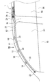
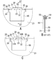
- FIG. 1 is a view showing an airbag apparatus according to the present embodiment.
- the airbag apparatus 1 mounted in the vehicle 90 is shown as viewed from the passenger compartment.
- the side wall 91 and the airbag device 1 of the vehicle 90 are schematically shown as viewed from the width direction of the vehicle 90 with the rear side of the vehicle 90 omitted.
- the airbag device 1 is shown through the inner surface of the vehicle 90.
- the front and rear in the vehicle 90 are simply referred to as front and rear
- the front-rear direction in the vehicle 90 is simply referred to as front-rear direction.
- the upper and lower portions in the vehicle 90 are simply referred to as upper and lower portions
- the vertical direction in the vehicle 90 is simply referred to as the vertical direction.
- the vehicle 90 has an upper roof rail 92, a front front pillar (A pillar) 93, a center pillar (B pillar) 94, and a rear rear pillar (C pillar) (see FIG. Not shown).
- the vehicle 90 includes a front door 95, a rear door 96, and window portions 97 and 98 provided in the doors 95 and 96.
- the airbag device 1 includes a cylindrical inflator 2, a fixing member 10, and an airbag (curtain airbag) 20.
- the airbag device 1 is disposed inside a trim and a head lining (not shown) attached to the vehicle body.
- the airbag 20 is folded into an elongated shape so as to be inflated and deployed, and is attached to the roof rail 92 along the front-rear direction at the upper part of the side wall 91 in the vehicle 90, and is arranged from the rear pillar to the front pillar 93.
- the folded airbag 20 is fixed to the vehicle body by a plurality of fixing members 10, and the fixing member 10 fixes a plurality of fixing cloths 30 included in the airbag 20 to the vehicle body.
- the inflator 2 is a cylinder type gas generator fixed to the vehicle body, and is inserted into the airbag 20 to generate gas in the airbag 20.
- the inflator 2 is attached to the roof rail 92 by a fixing means (not shown) and disposed above the center pillar 94.
- the inflator 2 In the event of a vehicle emergency or impact detection, the inflator 2 generates gas from a plurality of gas outlets 2 ⁇ / b> A and supplies the gas to the airbag 20. With this gas, the airbag 20 is inflated and deployed in a curtain shape from the upper part of the side wall 91 downward.
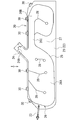
- FIG. 2 is a view showing the airbag 20 expanded on a plane.
- the airbag 20 is a rectangular bag, and is manufactured, for example, from a base fabric made of a cloth coated with a resin.
- the airbag 20 includes a front base fabric (front panel) 21 on the passenger side and a back base fabric (back panel) 22 on the side wall 91 side.
- the airbag 20 includes a connecting belt 23, a gas supply unit 24, and a plurality (six in FIG. 2) of fixed cloths 30.
- An inflator 2 (not shown in FIG. 2) is inserted into the gas supply unit 24.
- the front end of the airbag 20 is connected to the front pillar 93 by the connecting belt 23.
- the tip of the connecting belt 23 is fixed to the vehicle body.
- the front base fabric 21 and the back base fabric 22 are formed in the same shape, overlapped, and joined along the outer edge joint portion 25.
- the outer edge joint portion 25 divides the airbag 20, forms an inflatable portion 26 between the base fabrics 21 and 22, and defines an outer edge shape of the inflatable portion 26.
- the inflating part 26 is inflated by the gas generated by the inflator 2.
- the base fabrics 21 and 22 are joined by sewing and adhesion at the outer edge joint portion 25. That is, the base fabrics 21 and 22 are sewn one or more times along the outer edge joint portion 25, and the sewn portions are sealed with an adhesive. Thereby, the base fabrics 21 and 22 are joined in an airtight manner at the outer edge joint portion 25.
- the base fabrics 21 and 22 may be joined only by sewing at the outer edge joint portion 25.
- a front inflating portion 26A, a rear inflating portion 26B, and a connecting inflating portion 26C are formed by the outer edge joint portion 25.
- the inflating portions 26A to 26C each have a rectangular shape, and constitute the inflating portion 26 of the airbag 20 as a whole.
- the front inflating portion 26 ⁇ / b> A is disposed forward in the airbag 20.
- the rear inflating part 26 ⁇ / b> B is disposed rearward in the airbag 20.
- the connecting expansion part 26C connects the front expansion part 26A and the rear expansion part 26B.
- a non-expanding portion 27 is provided between the three expanding portions 26A to 26C.
- the airbag 20 has a plurality (four in FIG. 2) of internal joint portions 28 in the inflatable portion 26.
- the base fabrics 21 and 22 are joined at the inner joint portion 28 in the same manner as the outer edge joint portion 25.
- the tip of the internal joint portion 28 is joined in an annular shape within the expansion portion 26.
- the plurality of internal joints 28 are arranged apart from each other in the front-rear direction, and form a gas circulation part and an air chamber in the expansion part 26.
- the gas supply unit 24 is an opening for supplying gas into the airbag 20.
- the gas supply unit 24 is formed in the middle of the airbag 20 in the front-rear direction.
- the base fabrics 21 and 22 protrude obliquely upward from an upper edge (referred to as an upper edge) of the airbag 20 in the gas supply unit 24.
- the edge portions of the base fabrics 21 and 22 are continuously joined from the outer edge joint portion 25 except for the insertion port 24A at the tip.
- the gas supply part 24 is formed in the cylinder shape which both ends opened, and is provided in the upper edge part of the airbag 20 integrally.
- the inside of the gas supply unit 24 is connected to the outside of the airbag 20 through the insertion port 24A at one end, and is connected to the inside of the inflating unit 26 at the other end.
- the inflator 2 is inserted into the gas supply unit 24 from the insertion port 24 ⁇ / b> A and is disposed in the airbag 20.
- the gas supply unit 24 is fastened with a band (not shown) and fixed to the inflator 2 in an airtight manner.
- the inflator 2 generates gas in the gas supply unit 24 and supplies the gas into the airbag 20.
- the inflating part 26 is inflated by the gas, and develops in a curtain shape while eliminating the folded shape. That is, the gas is supplied to the front inflating portion 26A and is supplied from the connected inflating portion 26C to the rear inflating portion 26B. Block.
- the airbag 20 receives the front and rear occupants and protects the occupant's head.
- the airbag 20 is attached to the vehicle body by a plurality of fixed cloths 30 that are portions (fixed portions) fixed to the vehicle body of the airbag 20.
- the fixed cloth 30 is integrally formed on the upper edge of the airbag 20 and is fixed to each part of the vehicle body by the fixing member 10 (see FIG. 1).
- the fixing member 10 and the fixing cloth 30 will be described.
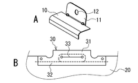
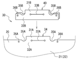
- FIG. 3 is a view showing the fixing member 10 and the fixing cloth 30 of the airbag 20.
- FIG. 3A is a perspective view of the fixing member 10.
- FIG. 3B is a view showing the fixed cloth 30 of the airbag 20.
- the fixed cloth 30 shown in FIG. 3B is sewn with a second sewing pattern (sewing portion is indicated by a broken line) described later.
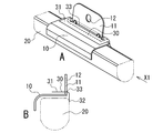
- FIG. 4 is a view showing the fixing member 10 attached to the airbag 20.
- FIG. 4A is a perspective view of the fixing member 10.
- 4B is a side view of the fixing member 10 and the airbag 20 as viewed from the direction of the arrow X1 in FIG. 4A.
- the airbag 20 is attached to the vehicle body in the folded shape shown in FIG.
- the fixing member 10 is a bracket for attaching the folded airbag 20 to the vehicle body. As shown in FIG. 3A, the fixing member 10 is composed of a plate-like member bent at a plurality of locations. The fixing member 10 (see FIG. 4) is disposed around the airbag 20 along the outer surface thereof, and holds the airbag 20.
- the fixing member 10 includes an attachment portion 11 that protrudes upward and an attachment hole 12 formed in the attachment portion 11.
- the attachment portion 11 is attached to the vehicle body by attachment means (not shown), for example, a bolt inserted into the attachment hole 12.
- the fixed cloth 30 has a rectangular protrusion 31 and a base 32, and the protrusion 31 protrudes from the edge of the airbag 20 (upper edge in FIG. 3B).
- the base 32 is a part located around the protrusion 31 within the edge of the airbag 20.
- the fixed cloth 30 has an insertion portion 33 into which the fixing member 10 is inserted.
- the insertion portion 33 is formed of a straight slit and is formed along the upper edge portion of the airbag 20, and the length of the insertion portion 33 is longer than the width of the attachment portion 11.
- the attachment part 11 of the fixing member 10 is inserted into the insertion part 33 provided in the fixing cloth 30 and penetrates the fixing cloth 30. Thereafter, the fixing member 10 is tilted and placed on the outer surface of the airbag 20 as shown in FIG.
- the protruding portion 31 of the fixing cloth 30 is bent along the insertion portion 33 of the attachment portion 11 when the fixing member 10 is tilted, and is arranged along the fixing member 10. Thereby, the fixing member 10 is attached to the fixing cloth 30 and the airbag 20.
- the fixing cloth 30 is fixed to the vehicle body by the fixing member 10 inserted into the insertion portion 33.
- the fixed cloth 30 will be described in detail.
- FIG. 5 is an exploded view of the fixed cloth 30.
- the fixed cloth 30 includes a main body cloth 34 and a reinforcing cloth 40 as illustrated.
- the main body cloth 34 is an integral cloth integrally formed with the airbag 20, and the main body cloth 34 has rectangular cloths formed on the base cloths 21 and 22 of the airbag 20, respectively.
- the fixed cloth 30 has two main body cloths 34 that overlap each other. Similar to the fixed cloth 30, the main body cloth 34 includes a protruding portion 31A, a base portion 32A, an insertion portion 33A, two concave portions 35A, and two through holes 36A.
- the concave portion 35A and the through hole 36A are formed in the base portion 32A on both sides of the protruding portion 31A.
- the reinforcing cloth 40 is made of a cloth separate from the airbag 20 and is formed in the same shape as the main body cloth 34. Similarly to the main body cloth 34, the reinforcing cloth 40 includes a protruding portion 31 ⁇ / b> B, a base portion 32 ⁇ / b> B, an insertion portion 33 ⁇ / b> B, a concave portion 35 ⁇ / b> B, and a through hole 36 ⁇ / b> B. Combined at points. At that time, the main body cloth 34 and the reinforcing cloth 40 are accurately overlapped and integrated by combining the positions of the recesses 35A and 35B and the through holes 36A and 36B.
- the reinforcing cloth 40 is a folded cloth obtained by folding a base cloth, and is formed of a plurality of overlapping cloths having the same shape, and is folded a predetermined number of times (two or more times in the present embodiment) and coupled to the main body cloth 34.
- the reinforcing cloth 40 reinforces the main body cloth 34 and increases the strength of the fixed cloth 30.
- the fixed cloth 30 is composed of a plurality of cloths including two main body cloths 34 and a plurality (multiple layers) of reinforcing cloths 40.
- the reinforcing cloth 40 is fixed to the vehicle body together with the main body cloth 34 by the fixing member 10 after being attached to the main body cloth 34. Next, a procedure for forming the reinforcing cloth 40 and the fixed cloth 30 will be described.
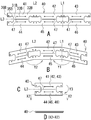
- FIG. 6 is a diagram illustrating a procedure for forming the reinforcing cloth 40.
- FIG. 6A is a development view of the reinforcing cloth 40.
- 6B and 6C are diagrams showing the reinforcing cloth 40 being folded.
- FIG. 6D is a cross-sectional view of the reinforcing cloth 40 as viewed in the direction of arrows X2-X2 in FIG. 6C.
- the reinforcing cloth 40 is made of a belt-like base cloth, and is folded in order at predetermined folding lines L1 to L3.
- the first and second folding lines L1 and L2 are set at two locations in the longitudinal direction of the reinforcing cloth 40 (left and right in FIG.
- the third fold line L3 is a center line in the width direction of the reinforcing cloth 40 (vertical direction in FIG. 6A).
- the reinforcing cloth 40 is divided into a plurality (six cloths in FIG. 6) of reinforcing pieces (small cloth) 41 to 46 by a plurality of folding lines L1 to L3.
- the plurality of reinforcing pieces 41 to 46 have the same shape as the main body cloth 34 and are formed side by side in the reinforcing cloth 40.
- the reinforcing cloth 40 includes a plurality of reinforcing pieces 41 to 46 that are integrally connected, and is formed symmetrically with respect to the third folding line L3. On both sides of the third fold line L3, three reinforcing pieces 41 to 43 and 44 to 46 are formed along the third fold line L3.
- the reinforcing cloth 40 has a slit 47 formed at the position of the fold. The slit 47 is provided between the reinforcing pieces 41 to 43 and 44 to 46 to facilitate the folding of the reinforcing cloth 40.
- the reinforcing cloth 40 has three slits 47 formed in the portion of the third fold line L3. The slit 47 is formed linearly along the third fold line L3 in the reinforcing cloth 40 so as not to divide the reinforcing cloth 40.
- the reinforcing cloth 40 is first folded at the first and second folding lines L1 and L2 (arrows Y1 and Y2 in FIG. 6B). Thereby, as shown to FIG. 6C and FIG. 6D, the reinforcement cloth 40 is folded in three and is folded by 1/3. Next, the reinforcing cloth 40 is folded back at the third folding line L3 (arrow Y3 in FIG. 6C). The reinforcing cloth 40 is folded into six by folding back three times, and is folded into one sixth. At that time, the reinforcing cloth 40 is folded while aligning the positions of the concave portions 35B and the through holes 36B of the reinforcing pieces 41 to 46, respectively.
- the reinforcing cloth 40 is composed of six cloths (reinforcing pieces 41 to 46) that are folded a predetermined number of times (here, three times) and overlapped, and formed in a shape corresponding to the main body cloth 34. The Subsequently, the folded reinforcing cloth 40 (see FIG. 5) is overlapped and bonded to the main body cloth 34.
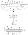
- FIG. 7 is a diagram showing the reinforcing cloth 40 and the main body cloth 34 before being joined.
- FIG. 7A is a diagram showing the reinforcing cloth 40 and the main body cloth 34 that are overlapped.
- FIG. 7B is a cross-sectional view of the reinforcing cloth 40 and the main body cloth 34 as seen in the direction of arrows X3-X3 in FIG. 7A.
- FIG. 7C is a cross-sectional view of the reinforcing cloth 40 and the main body cloth 34 as seen in the direction of arrows X4-X4 in FIG. 7A.
- the main body cloth 34 is sandwiched between the reinforcing cloths 40 before the fixing cloth 30 is joined, that is, the main body cloth 34 is disposed between the folded reinforcing cloths 40.
- the cloth 34 and the reinforcing cloth 40 are overlapped.
- three reinforcing cloths 40 are arranged on both surfaces of the main body cloth 34 while aligning the positions of the recesses 35 (35A, 35B) and the through holes 36 (36A, 36B).
- the insertion part 33 (33A, 33B) is arrange
- the main body cloth 34 and the reinforcing cloth 40 are joined by sewing.
- the recesses 35 are provided to facilitate bending of the protrusion 31 when the protrusion 31 of the fixed cloth 30 is bent by the fixing member 10. Accordingly, when the ease of bending the protruding portion 31 does not matter, the recessed portion 35 may not be provided in the fixed cloth 30.
- the corner between the protruding portion 31 and the base portion 32 is formed in a curved shape, and the protruding portion 31 and the base portion 32 are connected by the curved portion.
- FIG. 8 is a view showing a first sewing pattern of the main body cloth 34 and the reinforcing cloth 40.
- the main body cloth 34 and the reinforcing cloth 40 are overlapped and sewn together at the sewing portions 37A and 38A.
- the main body cloth 34 and the reinforcing cloth 40 are joined by two types of sewing parts, that is, the attachment sewing part 37A for attaching the reinforcing cloth 40 to the main body cloth 34, and the reinforcing sewing part 38A for reinforcing the fixed cloth 30 and A fixed cloth 30 is formed on the bag 20.
- the fixed cloth 30 has two types of sewing portions 37A and 38A, and is connected by one attachment sewing portion 37A and one reinforcing sewing portion 38A.
- the attachment sewing portion 37A is formed linearly across the base portion 32 of the fixed cloth 30, and the entire base portion 32 is thereby sewn.
- the attachment sewing portion 37 ⁇ / b> A is formed to the outside of the reinforcing cloth 40 while being formed on the base cloth 32 and the base portion 32 of the reinforcing cloth 40.
- the reinforcing cloth 40 is attached to the main body cloth 34 by sewing at the attachment sewing portion 37A.
- the bottom of the recessed part 35 is a part where load is easily applied, and the attachment sewing part 37A needs to be formed across the lower part of the bottom of at least two recessed parts 35.
- the attachment sewing portion 37 ⁇ / b> A only needs to be formed between the lower portions of the bottom of the concave portion 35, and may not be formed outside the lower portion of the bottom of the concave portion 35.
- the attachment sewing portion 37A is preferably formed as described above in order to reliably cope with the load on the fixed cloth 30.
- the reinforcing sewing portion 38A is formed on the fixed fabric 30 by sewing the fixed fabric 30 along the insertion portion 33, and is formed in an annular shape (rectangular shape in FIG. 8) surrounding the insertion portion 33 of the fixed fabric 30 to be fixed.
- the insertion part 33 of the cloth 30 is reinforced.
- the reinforcing cloth 40 and the main body cloth 34 are sewn into a rectangular shape by a reinforcing sewing portion 38A. In other words, the reinforcing cloth 40 and the main body cloth 34 are integrally reinforced by the reinforcing sewing portion 38A.
- the reinforcement sewing portion 38 ⁇ / b> A reinforces the peripheral portion of the insertion portion 33 and increases the strength around the insertion portion 33.
- the two sewing portions 37 ⁇ / b> A and 38 ⁇ / b> A are separated from each other in the fixed cloth 30. That is, the sewing portions 37 ⁇ / b> A and 38 ⁇ / b> A are independent from each other and are formed separately on the fixed cloth 30.
- the fixed cloth 30 is joined by two times of sewing.
- the fixed cloth 30 is coupled by one sewing.
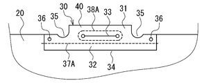
- FIG. 9 is a diagram illustrating a second sewing pattern of the main body cloth 34 and the reinforcing cloth 40.
- FIG. 9A is a diagram illustrating the fixed cloth 30 after being joined.
- 9B and 9C are diagrams illustrating a sewing process of the fixed cloth 30.
- the sewing parts 37B and 38B of the second sewing pattern are basically the same sewing parts as the sewing parts 37A and 38A of the first sewing pattern. However, in the second sewing pattern, as shown in the drawing, the attachment sewing portion 37B and the reinforcement sewing portion 38B are connected and formed continuously by one sewing. Therefore, the entire shape of the sewing portions 37B and 38B is set to a shape that can be written with a single stroke.
- the attachment sewing part 37B and the reinforcement sewing part 38B have a contact part or an overlapping part.
- the linear portions of the sewing portions 37B and 38B are provided at the same position on the base portion 32.
- the reinforcement sewing portion 38B is formed so as to overlap the intermediate portion of the attachment sewing portion 37B.
- the entire sewing portions 37B and 38B are continuously sewn as in a single stroke.
- sewing is started from one end of the attachment sewing portion 37B (see FIG. 9B), and when the attachment sewing portion 37B is formed to a predetermined position, the sewing direction is changed and the portion to be sewn is attached to the sewing The portion 37B is changed to the reinforcement sewing portion 38B.
- the fixed cloth 30 is sewn in a rectangular shape so as to surround the insertion portion 33 to form a reinforcing sewing portion 38B (see FIG. 9C). Subsequently, sewing is performed to the other end of the attachment sewing portion 37B, and the sewing is finished.
- the entire reinforcement sewing portion 38B is formed, and then the remaining portion of the attachment sewing portion 37B is formed.
- a linear attachment sewing portion 37B and a rectangular reinforcement sewing portion 38B are continuously formed by one sewing, whereby the main body cloth 34 and the reinforcement cloth 40 are sewn together, and the reinforcement cloth 40 is sewn. Is attached to the body cloth 34.
- the reinforcement sewing portion 38 ⁇ / b> B is formed around the insertion portion 33 and reinforces the fixed cloth 30 around the insertion portion 33.
- the fixed cloth 30 is formed by a plurality of combined cloths and provided on the airbag 20. Thereafter, the fixing member 10 (see FIG. 4) is attached to the fixing cloth 30.
- the reinforcing cloth 40 is folded a predetermined number of times and joined to the main body cloth 34, the handling and management of the reinforcing cloth 40 is easy. Since the reinforcing cloth 40 only needs to be folded a predetermined number of times, it is possible to reduce the trouble of checking the number of reinforcing cloths 40. Further, the fixed cloth 30 made of a plurality of cloths can be easily formed on the airbag 20 by the main body cloth 34 and the reinforcing cloth 40. It is possible to prevent the number of the fixing cloths 30 from being wrong. Since the fixed cloth 30 can be reliably reinforced by the reinforcing cloth 40, the strength required for the fixed cloth 30 can be ensured. Since the labor required for forming the fixed cloth 30 can be reduced, the work time required for forming the fixed cloth 30 can be shortened.
- the main body cloth 34 can be reinforced from both sides by arranging the main body cloth 34 between the folded reinforcing cloths 40. Since the main body cloth 34 and the reinforcing cloth 40 are overlapped and sewn together by the sewing portions 37 and 38, the reinforcing cloth 40 can be easily coupled to the main body cloth 34.
- the sewing of the sewing parts 37B and 38B can be performed in one step without interruption. As a result, since the process and time for sewing can be reduced, the work efficiency of sewing can be improved.
- the reinforcing cloth 40 is attached to the main body cloth 34 by the attachment sewing portion 37 and the fixed cloth 30 is reinforced by the reinforcing sewing portion 38, the reinforcing cloth 40 and the main body cloth 34 can be coupled with high strength. Further, the strength of the fixed cloth 30 can be increased by reinforcing the reinforcing sewing portion 38. Since the plurality of cloths of the fixed cloth 30 receive external force jointly without receiving external force alone, the fixed cloth 30 has high strength against external force and is not easily torn. When the insertion portion 33 is reinforced by the reinforcing sewing portion 38 formed around the insertion portion 33, the strength of the peripheral portion of the insertion portion 33 can be increased.
- the fixed cloth 30 is difficult to be broken around the insertion portion 33, it is possible to prevent the fixed cloth 30 from being detached from the fixed member 10.
- the reinforcing sewing portion 38 is formed so as to surround the insertion portion 33, the entire area around the insertion portion 33 can be reinforced.
- the reinforcing cloth 40 can be firmly attached to the main body cloth 34 at the base portion 32. Further, the force applied to the fixed cloth 30 acts on the sewn base 32 of the main body cloth 34 and the reinforcing cloth 40, but the protrusion 31 of the fixed cloth 30 or the base of the protrusion 31 may be damaged by an external force. Can be prevented.
- the reinforcing cloth 40 is not limited to the above folding method, and may be folded in other ways.
- the reinforcing cloth 40 may be formed so as to be composed of a plurality of overlapping cloths after being folded.
- the same number of reinforcing cloths 40 may be arranged on both sides of the main body cloth 34, or may be arranged so that the number of reinforcing cloths 40 is different on each side of the main body cloth 34.
- the main body cloth 34 may be disposed on one surface of the reinforcing cloth 40 without being disposed between the folded reinforcing cloths 40.
- the attachment sewing portion 37 may be formed in a shape other than a straight shape (for example, a curved shape or a wave shape).
- the reinforcing sewing portion 38 may be formed in a shape other than a rectangular shape (for example, a circular shape or a polygonal shape).
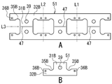
- 10 and 11 are diagrams showing reinforcing cloths 50 and 51 according to another embodiment.
- 10A and 11A are development views showing the reinforcing fabrics 50 and 51 before folding.
- 10B and 11B are diagrams showing the reinforcing cloths 50 and 51 after being folded.
- the reinforcing cloth 50 shown in FIG. 10 is different from the reinforcing cloth 40 described above only in the shape of the insertion portion 33B.
- the insertion portion 33B of the reinforcing cloth 50 is formed of a slit having a predetermined width.
- the reinforcing cloth 50 is folded along the folding lines L1 to L3 and coupled to the main body cloth.
- the insertion portion 33A of the main body cloth 34 is formed in the same shape as the insertion portion 33B of the reinforcing cloth 50.
- the reinforcing cloth 51 is configured in the same manner as the above-described reinforcing cloth 40 except for the insertion portion 39.
- the insertion portion 39 of the reinforcing cloth 51 is a fixing hole into which a fixing member (not shown) such as a bolt is inserted.
- the reinforcing cloth 51 is folded along the folding lines L1 to L3 and coupled to the main body cloth.
- An insertion portion (fixed hole) having the same shape as the insertion portion 39 is formed in the main body cloth 34 in place of the insertion portion 33A.
- the fixed cloth 30 is fixed to the vehicle body by a fixing member inserted into the insertion portion 39.
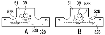
- FIG. 12 and 13 are diagrams showing two sewing patterns of the reinforcing cloth 51.
- FIG. 12A In the sewing pattern shown in FIG. 12, similarly to the above-described reinforcing cloth 40 (see FIG. 9), the attachment sewing portion 52A and the reinforcing sewing portion 53A are continuously connected and formed continuously by one sewing.
- the reinforcing cloth 51 and the main body cloth 34 are continuously sewn by the attachment sewing portion 52A and the reinforcing sewing portion 53A.
- sewing is started from one end of the attachment sewing portion 52A, formed to a predetermined position, and then the entire insertion portion 39 is surrounded and sewn.
- an annular reinforcing sewing portion 53A see FIG.
- the attachment sewing portion 52A is formed in the reinforcing cloth 51 without traversing the base portion 32B.
- the attachment sewing portion 52B and the reinforcement sewing portion 53B are formed continuously.
- the reinforcing sewing portion 53B is formed around the insertion portion 39 so as to surround a part of the insertion portion 39 (here, the lower half).
- the reinforcing sewing portion 53 ⁇ / b> B is formed so as to surround a part of the insertion portion 39 along a part of the insertion portion 39, and reinforces a part around the insertion portion 39.
- the reinforcement sewing portion of the fixed cloth 30 is formed in various shapes and positions according to the portion of the fixed cloth 30 to be reinforced.
- FIG. 14 is a view showing a reinforcing cloth 54 that is partially different from the reinforcing cloth 51 shown in FIG.
- FIG. 14A is a development view showing the reinforcing cloth 54 before folding.
- FIG. 14B is a diagram illustrating the reinforcing cloth 54 after being folded.
- the reinforcing cloth 54 shown in FIG. 14 does not have the recess 35B and the through hole 36B.
- the reinforcing cloth 54 is configured in the same manner as the above-described reinforcing cloth 51 except for the concave portion 35B and the through hole 36B.
- the reinforcing cloth 54 is folded with the edges aligned, and the reinforcing cloth 54 and the main body cloth 34 are overlapped with the edges aligned.
- the protective cloth is disposed between the fixing member 10 (see FIGS. 3 and 4) and the airbag 20 to protect the airbag 20 from the fixing member 10.
- a protective cloth is attached to the airbag 20 in addition to the above-described reinforcing cloth 40 (see FIGS. 5 to 7).
- FIG. 15 is a diagram showing the protective cloth 60.
- the protective cloth 60 includes a protective portion 61 that protects the airbag 20 and a coupling portion 62 that is coupled to the airbag 20.
- the protection part 61 has a rectangular shape and is formed integrally with the coupling part 62.
- the coupling portion 62 is formed in the same shape as the reinforcing pieces 41 to 46 of the reinforcing cloth 40 and the folded reinforcing cloth 40. Accordingly, the coupling portion 62 includes the insertion portion 33C, the concave portion 35C, and the through hole 36C.
- the coupling part 62 is coupled to the airbag 20 simultaneously with the coupling of the reinforcing cloth 40 to the main body cloth 34. Thereby, the protective cloth 60 is attached to the airbag 20.
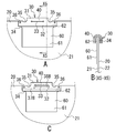
- FIG. 16 is a view showing the protective cloth 60 before and after being attached to the airbag 20.
- 16A is a view showing the fixed cloth 30 and the protective cloth 60 before sewing
- FIG. 16B is a cross-sectional view of the fixed cloth 30 and the protective cloth 60 taken along line X5-X5 in FIG. 16A
- FIG. 16C is a diagram showing the fixed cloth 30 and the protective cloth 60 after sewing.
- the main body cloth 34 is disposed between the reinforcing cloths 40
- the protective cloth 60 is disposed at a position where the reinforcing cloth 40 is coupled to the main body cloth 34.
- the protective cloth 60 is sandwiched between the reinforcing cloth 40 and the main body cloth 34 while the coupling portion 62 is aligned with the reinforcing cloth 40 on the front base cloth 21 side of the airbag 20.
- the main body cloth 34 and the reinforcing cloth 40 are sewn to continuously form the attachment sewing portion 37B and the reinforcing sewing portion 38B, and at the same time, the main body cloth 34, the reinforcing cloth 40, and the protective cloth.
- the connecting portion 62 is connected to the airbag 20 by stitching 60 together.
- the protective cloth 60 is attached to the airbag 10 together with the reinforcing cloth 40 when the reinforcing cloth 40 is coupled to the main body cloth 34.
- the fixing member 10 (see FIGS. 3 and 4) is attached to the fixing cloth 30 and the airbag 20 in the same manner as described above.
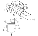
- FIG. 17 is a view showing the fixing member 10 attached to the airbag 20.
- FIG. 17A is a perspective view of the fixing member 10.
- FIG. 17B is a side view of the fixing member 10 and the airbag 20 as viewed from the direction of the arrow X6 in FIG. 17A.
- the protective cloth 60 is disposed on the outer surface of the folded airbag 20 as shown in the figure. When the fixing member 10 is attached to the airbag 20, the protective cloth 60 is disposed between the fixing member 10 and the airbag 20. Further, the protective cloth 60 is disposed on the entire portion of the airbag 20 that faces the fixing member 10.
- the airbag 20 can be protected from the fixing member 10 by providing the airbag 20 with the protective cloth 60.
- the protective cloth 60 can also prevent the edge of the fixing member 10 from contacting the airbag 20. Therefore, the airbag 20 can be prevented from being damaged by the fixing member 10. Since the protective cloth 60 is attached to the airbag 20 at the same time when the reinforcing cloth 40 is joined, the process and work time for attaching the protective cloth 60 can be reduced.
- the protective cloth 60 may be disposed between the folded reinforcing cloths 40 or on one surface of the reinforcing cloth 40. Even in this case, the protective cloth 60 can be easily attached to the airbag 20. Two or more protective cloths 60 may be provided on the airbag 20.
- FIG. 18 is a development view showing a reinforcing cloth 55 and a protective cloth 65 of another embodiment.
- the protective cloth 65 is formed integrally with the reinforcing cloth 55 as shown in the figure.
- the reinforcing cloth 55 is configured in the same manner as the above-described reinforcing cloth 40 except for the protective cloth 65.
- the protective cloth 65 is made of a rectangular cloth formed on one reinforcing piece 46. The protective cloth 65 is attached to the airbag 20 together with the reinforcing cloth 55.
- FIG. 19 is a view showing the protective cloth 65 before and after being attached to the airbag 20.
- 19A is a view showing the fixed cloth 30 and the protective cloth 65 before sewing
- FIG. 19B is a cross-sectional view of the fixed cloth 30 and the protective cloth 65 taken along line X7-X7 in FIG. 19A.
- FIG. 19C is a diagram showing the fixed cloth 30 and the protective cloth 65 after sewing.
- the main body cloth 34 is disposed between the reinforcing cloths 55.
- the reinforcing cloth 55 is folded so that the protective cloth 65 is positioned on the outermost side on the front base cloth 21 side of the airbag 20. Subsequently, as shown in FIG.
- the main body cloth 34 and the reinforcing cloth 55 are stitched together to join the reinforcing cloth 55 to the main body cloth 34.
- the protective cloth 65 is attached to the airbag 20 by joining the reinforcing cloth 55 and the main body cloth 34.
- the airbag 20 can be protected from the fixing member 10 by the protective cloth 65.
- the protective cloth 65 since the protective cloth 65 is attached to the airbag 20 at the same time as the reinforcement cloth 55 is joined, the process and work time for attaching the protective cloth 65 can be reduced.
- the protection cloth 65 may be arranged at a position different from the above by changing how the reinforcing cloth 55 is folded.
- the protective cloth 65 may be provided on the reinforcing pieces 41 to 45 other than the reinforcing piece 46.
- the protective cloth 65 may be provided at a plurality of locations of the reinforcing cloth 55.
Landscapes
- Engineering & Computer Science (AREA)
- Mechanical Engineering (AREA)
- Air Bags (AREA)
Applications Claiming Priority (2)
| Application Number | Priority Date | Filing Date | Title |
|---|---|---|---|
| JP2011-141092 | 2011-06-24 | ||
| JP2011141092A JP5839449B2 (ja) | 2011-06-24 | 2011-06-24 | エアバッグ装置 |
Publications (1)
| Publication Number | Publication Date |
|---|---|
| WO2012176732A1 true WO2012176732A1 (ja) | 2012-12-27 |
Family
ID=47422569
Family Applications (1)
| Application Number | Title | Priority Date | Filing Date |
|---|---|---|---|
| PCT/JP2012/065503 Ceased WO2012176732A1 (ja) | 2011-06-24 | 2012-06-18 | エアバッグ装置 |
Country Status (2)
| Country | Link |
|---|---|
| JP (1) | JP5839449B2 (cg-RX-API-DMAC7.html) |
| WO (1) | WO2012176732A1 (cg-RX-API-DMAC7.html) |
Cited By (1)
| Publication number | Priority date | Publication date | Assignee | Title |
|---|---|---|---|---|
| US9199598B2 (en) | 2014-02-26 | 2015-12-01 | Takata Corporation | Airbag and airbag apparatus |
Families Citing this family (5)
| Publication number | Priority date | Publication date | Assignee | Title |
|---|---|---|---|---|
| US9156427B2 (en) * | 2014-01-08 | 2015-10-13 | Autoliv Asp, Inc. | Cost-effective use of one-piece woven fabric for curtain airbags |
| JP6084588B2 (ja) * | 2014-06-11 | 2017-02-22 | オートリブ ディベロップメント エービー | カーテンエアバッグ装置 |
| JP6875829B2 (ja) * | 2016-10-31 | 2021-05-26 | セーレン株式会社 | エアバッグ |
| US11628796B2 (en) * | 2021-08-23 | 2023-04-18 | ZF Passive Safety Systems US Inc. | Curtain airbag deployment ramp with mounting tabs |
| KR102656157B1 (ko) * | 2022-03-14 | 2024-04-11 | 아우토리브 디벨롭먼트 아베 | 자동차의 커튼 에어백 |
Citations (8)
| Publication number | Priority date | Publication date | Assignee | Title |
|---|---|---|---|---|
| JPH07237514A (ja) * | 1994-03-03 | 1995-09-12 | Bridgestone Corp | エアバッグ装置におけるエアバッグ |
| JP2000033846A (ja) * | 1998-07-17 | 2000-02-02 | Toyota Motor Corp | 頭部保護エアバッグ装置 |
| JP2003291771A (ja) * | 2002-04-01 | 2003-10-15 | Nippon Plast Co Ltd | エアバッグ装置 |
| JP2006515544A (ja) * | 2002-11-29 | 2006-06-01 | ティーケー ホールディングズ インコーポレーテッド | エアバッグ織物ディフューザ |
| JP2006168690A (ja) * | 2004-12-20 | 2006-06-29 | Toyoda Gosei Co Ltd | 頭部保護エアバッグ |
| JP2009023439A (ja) * | 2007-07-18 | 2009-02-05 | Nippon Plast Co Ltd | エアバッグ装置 |
| JP2010030342A (ja) * | 2008-07-25 | 2010-02-12 | Seiren Co Ltd | カーテンエアバッグ |
| JP2011500451A (ja) * | 2007-10-30 | 2011-01-06 | タカタ株式会社 | 乗員を保護するためのエアバッグ装置 |
Family Cites Families (6)
| Publication number | Priority date | Publication date | Assignee | Title |
|---|---|---|---|---|
| JPH0811655A (ja) * | 1994-06-28 | 1996-01-16 | Nippon Plast Co Ltd | エアバッグ |
| JP4743807B2 (ja) * | 2000-12-20 | 2011-08-10 | タカタ株式会社 | カーテンエアバッグ |
| JP3838645B2 (ja) * | 2003-04-14 | 2006-10-25 | 本田技研工業株式会社 | 乗員拘束装置 |
| JP2005104234A (ja) * | 2003-09-29 | 2005-04-21 | Nippon Plast Co Ltd | エアバッグ装置 |
| JP2009001259A (ja) * | 2007-05-23 | 2009-01-08 | Toyoda Gosei Co Ltd | エアバッグ装置 |
| JP5342377B2 (ja) * | 2009-08-28 | 2013-11-13 | 日本プラスト株式会社 | エアバッグ装置 |
-
2011
- 2011-06-24 JP JP2011141092A patent/JP5839449B2/ja active Active
-
2012
- 2012-06-18 WO PCT/JP2012/065503 patent/WO2012176732A1/ja not_active Ceased
Patent Citations (8)
| Publication number | Priority date | Publication date | Assignee | Title |
|---|---|---|---|---|
| JPH07237514A (ja) * | 1994-03-03 | 1995-09-12 | Bridgestone Corp | エアバッグ装置におけるエアバッグ |
| JP2000033846A (ja) * | 1998-07-17 | 2000-02-02 | Toyota Motor Corp | 頭部保護エアバッグ装置 |
| JP2003291771A (ja) * | 2002-04-01 | 2003-10-15 | Nippon Plast Co Ltd | エアバッグ装置 |
| JP2006515544A (ja) * | 2002-11-29 | 2006-06-01 | ティーケー ホールディングズ インコーポレーテッド | エアバッグ織物ディフューザ |
| JP2006168690A (ja) * | 2004-12-20 | 2006-06-29 | Toyoda Gosei Co Ltd | 頭部保護エアバッグ |
| JP2009023439A (ja) * | 2007-07-18 | 2009-02-05 | Nippon Plast Co Ltd | エアバッグ装置 |
| JP2011500451A (ja) * | 2007-10-30 | 2011-01-06 | タカタ株式会社 | 乗員を保護するためのエアバッグ装置 |
| JP2010030342A (ja) * | 2008-07-25 | 2010-02-12 | Seiren Co Ltd | カーテンエアバッグ |
Cited By (1)
| Publication number | Priority date | Publication date | Assignee | Title |
|---|---|---|---|---|
| US9199598B2 (en) | 2014-02-26 | 2015-12-01 | Takata Corporation | Airbag and airbag apparatus |
Also Published As
| Publication number | Publication date |
|---|---|
| JP5839449B2 (ja) | 2016-01-06 |
| JP2013006539A (ja) | 2013-01-10 |
Similar Documents
| Publication | Publication Date | Title |
|---|---|---|
| JP5017141B2 (ja) | カーテンエアバッグ及びその製造方法 | |
| JP4946858B2 (ja) | 側突用エアバッグ装置 | |
| JP5839449B2 (ja) | エアバッグ装置 | |
| WO2019026663A1 (ja) | 車両用サイドエアバッグ装置 | |
| JP2005280470A (ja) | 助手席用エアバッグ | |
| JP5852407B2 (ja) | ベントホールが形成されたエアバック | |
| US11059446B2 (en) | Airbag | |
| JP2008001196A (ja) | 助手席用エアバッグ | |
| JP2013023028A (ja) | エアバッグ装置 | |
| JP5314918B2 (ja) | エアバッグ及びエアバッグ装置 | |
| JP7186108B2 (ja) | カーテンエアバッグ及びカーテンエアバッグ装置 | |
| JP6420157B2 (ja) | エアバッグ | |
| JP6445125B2 (ja) | エアバッグ装置 | |
| WO2012176733A1 (ja) | エアバッグ装置 | |
| WO2013011900A1 (ja) | エアバッグ装置 | |
| JP2018016163A (ja) | エアバッグ | |
| JP4884067B2 (ja) | エアバッグ | |
| JP5407889B2 (ja) | エアバッグ及びエアバッグ装置 | |
| WO2016035457A1 (ja) | 助手席用エアバッグ及びそれを備えるエアバッグ装置 | |
| JP6379444B2 (ja) | エアバッグ装置 | |
| JP2013023029A (ja) | エアバッグ装置 | |
| JP5016431B2 (ja) | エアバッグ | |
| CN115551745B (zh) | 车辆用安全气囊装置及其制造方法 | |
| JP2002308035A (ja) | 頭部保護エアバッグ装置 | |
| JP5413343B2 (ja) | サイドエアバッグ装置 |
Legal Events
| Date | Code | Title | Description |
|---|---|---|---|
| 121 | Ep: the epo has been informed by wipo that ep was designated in this application |
Ref document number: 12802804 Country of ref document: EP Kind code of ref document: A1 |
|
| NENP | Non-entry into the national phase |
Ref country code: DE |
|
| 122 | Ep: pct application non-entry in european phase |
Ref document number: 12802804 Country of ref document: EP Kind code of ref document: A1 |