WO2012176316A1 - シフト切り替え装置 - Google Patents
シフト切り替え装置 Download PDFInfo
- Publication number
- WO2012176316A1 WO2012176316A1 PCT/JP2011/064462 JP2011064462W WO2012176316A1 WO 2012176316 A1 WO2012176316 A1 WO 2012176316A1 JP 2011064462 W JP2011064462 W JP 2011064462W WO 2012176316 A1 WO2012176316 A1 WO 2012176316A1
- Authority
- WO
- WIPO (PCT)
- Prior art keywords
- shift
- switch
- range
- switching device
- lever
- Prior art date
- Legal status (The legal status is an assumption and is not a legal conclusion. Google has not performed a legal analysis and makes no representation as to the accuracy of the status listed.)
- Ceased
Links
Images
Classifications
-
- F—MECHANICAL ENGINEERING; LIGHTING; HEATING; WEAPONS; BLASTING
- F16—ENGINEERING ELEMENTS AND UNITS; GENERAL MEASURES FOR PRODUCING AND MAINTAINING EFFECTIVE FUNCTIONING OF MACHINES OR INSTALLATIONS; THERMAL INSULATION IN GENERAL
- F16H—GEARING
- F16H59/00—Control inputs to control units of change-speed- or reversing-gearings for conveying rotary motion
- F16H59/02—Selector apparatus
- F16H59/0217—Selector apparatus with electric switches or sensors not for gear or range selection, e.g. for controlling auxiliary devices
-
- B—PERFORMING OPERATIONS; TRANSPORTING
- B60—VEHICLES IN GENERAL
- B60K—ARRANGEMENT OR MOUNTING OF PROPULSION UNITS OR OF TRANSMISSIONS IN VEHICLES; ARRANGEMENT OR MOUNTING OF PLURAL DIVERSE PRIME-MOVERS IN VEHICLES; AUXILIARY DRIVES FOR VEHICLES; INSTRUMENTATION OR DASHBOARDS FOR VEHICLES; ARRANGEMENTS IN CONNECTION WITH COOLING, AIR INTAKE, GAS EXHAUST OR FUEL SUPPLY OF PROPULSION UNITS IN VEHICLES
- B60K20/00—Arrangement or mounting of change-speed gearing control devices in vehicles
- B60K20/02—Arrangement or mounting of change-speed gearing control devices in vehicles of initiating means
- B60K20/08—Dashboard means
-
- B—PERFORMING OPERATIONS; TRANSPORTING
- B60—VEHICLES IN GENERAL
- B60K—ARRANGEMENT OR MOUNTING OF PROPULSION UNITS OR OF TRANSMISSIONS IN VEHICLES; ARRANGEMENT OR MOUNTING OF PLURAL DIVERSE PRIME-MOVERS IN VEHICLES; AUXILIARY DRIVES FOR VEHICLES; INSTRUMENTATION OR DASHBOARDS FOR VEHICLES; ARRANGEMENTS IN CONNECTION WITH COOLING, AIR INTAKE, GAS EXHAUST OR FUEL SUPPLY OF PROPULSION UNITS IN VEHICLES
- B60K20/00—Arrangement or mounting of change-speed gearing control devices in vehicles
- B60K20/02—Arrangement or mounting of change-speed gearing control devices in vehicles of initiating means
-
- F—MECHANICAL ENGINEERING; LIGHTING; HEATING; WEAPONS; BLASTING
- F16—ENGINEERING ELEMENTS AND UNITS; GENERAL MEASURES FOR PRODUCING AND MAINTAINING EFFECTIVE FUNCTIONING OF MACHINES OR INSTALLATIONS; THERMAL INSULATION IN GENERAL
- F16H—GEARING
- F16H59/00—Control inputs to control units of change-speed- or reversing-gearings for conveying rotary motion
- F16H59/02—Selector apparatus
-
- F—MECHANICAL ENGINEERING; LIGHTING; HEATING; WEAPONS; BLASTING
- F16—ENGINEERING ELEMENTS AND UNITS; GENERAL MEASURES FOR PRODUCING AND MAINTAINING EFFECTIVE FUNCTIONING OF MACHINES OR INSTALLATIONS; THERMAL INSULATION IN GENERAL
- F16H—GEARING
- F16H59/00—Control inputs to control units of change-speed- or reversing-gearings for conveying rotary motion
- F16H59/02—Selector apparatus
- F16H59/0204—Selector apparatus for automatic transmissions with means for range selection and manual shifting, e.g. range selector with tiptronic
-
- F—MECHANICAL ENGINEERING; LIGHTING; HEATING; WEAPONS; BLASTING
- F16—ENGINEERING ELEMENTS AND UNITS; GENERAL MEASURES FOR PRODUCING AND MAINTAINING EFFECTIVE FUNCTIONING OF MACHINES OR INSTALLATIONS; THERMAL INSULATION IN GENERAL
- F16H—GEARING
- F16H59/00—Control inputs to control units of change-speed- or reversing-gearings for conveying rotary motion
- F16H59/02—Selector apparatus
- F16H59/08—Range selector apparatus
- F16H59/10—Range selector apparatus comprising levers
-
- F—MECHANICAL ENGINEERING; LIGHTING; HEATING; WEAPONS; BLASTING
- F16—ENGINEERING ELEMENTS AND UNITS; GENERAL MEASURES FOR PRODUCING AND MAINTAINING EFFECTIVE FUNCTIONING OF MACHINES OR INSTALLATIONS; THERMAL INSULATION IN GENERAL
- F16H—GEARING
- F16H59/00—Control inputs to control units of change-speed- or reversing-gearings for conveying rotary motion
- F16H59/02—Selector apparatus
- F16H59/08—Range selector apparatus
- F16H59/12—Range selector apparatus comprising push button devices
-
- F—MECHANICAL ENGINEERING; LIGHTING; HEATING; WEAPONS; BLASTING
- F16—ENGINEERING ELEMENTS AND UNITS; GENERAL MEASURES FOR PRODUCING AND MAINTAINING EFFECTIVE FUNCTIONING OF MACHINES OR INSTALLATIONS; THERMAL INSULATION IN GENERAL
- F16H—GEARING
- F16H63/00—Control outputs from the control unit to change-speed- or reversing-gearings for conveying rotary motion or to other devices than the final output mechanism
- F16H63/40—Control outputs from the control unit to change-speed- or reversing-gearings for conveying rotary motion or to other devices than the final output mechanism comprising signals other than signals for actuating the final output mechanisms
- F16H63/42—Ratio indicator devices
- F16H2063/423—Range indicators for automatic transmissions, e.g. showing selected range or mode
-
- F—MECHANICAL ENGINEERING; LIGHTING; HEATING; WEAPONS; BLASTING
- F16—ENGINEERING ELEMENTS AND UNITS; GENERAL MEASURES FOR PRODUCING AND MAINTAINING EFFECTIVE FUNCTIONING OF MACHINES OR INSTALLATIONS; THERMAL INSULATION IN GENERAL
- F16H—GEARING
- F16H61/00—Control functions within control units of change-speed- or reversing-gearings for conveying rotary motion ; Control of exclusively fluid gearing, friction gearing, gearings with endless flexible members or other particular types of gearing
- F16H61/02—Control functions within control units of change-speed- or reversing-gearings for conveying rotary motion ; Control of exclusively fluid gearing, friction gearing, gearings with endless flexible members or other particular types of gearing characterised by the signals used
- F16H61/0202—Control functions within control units of change-speed- or reversing-gearings for conveying rotary motion ; Control of exclusively fluid gearing, friction gearing, gearings with endless flexible members or other particular types of gearing characterised by the signals used the signals being electric
- F16H61/0248—Control units where shifting is directly initiated by the driver, e.g. semi-automatic transmissions
-
- Y—GENERAL TAGGING OF NEW TECHNOLOGICAL DEVELOPMENTS; GENERAL TAGGING OF CROSS-SECTIONAL TECHNOLOGIES SPANNING OVER SEVERAL SECTIONS OF THE IPC; TECHNICAL SUBJECTS COVERED BY FORMER USPC CROSS-REFERENCE ART COLLECTIONS [XRACs] AND DIGESTS
- Y10—TECHNICAL SUBJECTS COVERED BY FORMER USPC
- Y10T—TECHNICAL SUBJECTS COVERED BY FORMER US CLASSIFICATION
- Y10T74/00—Machine element or mechanism
- Y10T74/20—Control lever and linkage systems
- Y10T74/20012—Multiple controlled elements
- Y10T74/20018—Transmission control
- Y10T74/20073—Control of plural mechanisms [e.g., control of transmission and control of 4 - wheel drive]
Definitions
- This invention relates to a shift switching device.
- the shift lever is located between the original position and the drive position (D position), reverse position (R position), shift up position (+ position), and shift down position ( ⁇ position). It is configured so that it can be tilted.
- the range designation positions are set to the front, rear, left, and right with respect to the original position.
- the shift range of the automatic transmission is switched by tilting the shift lever forward, rear, left, or right from the original position.
- a push-type neutral switch and a parking switch are provided further forward than a shift lever at a remote position of the driver's seat. By operating the neutral switch or the parking switch, the automatic transmission is switched to the neutral range or the parking range.
- the driver can operate the shift lever to one of the range designated positions by tilting the shift lever in one direction from the original position. Further, the neutral switch and the parking switch can be operated simply by pressing the operation surface in one direction. As described above, since the range can be easily switched, the driver is required to perform a careful operation. On the other hand, if the operation of the shift lever and the neutral switch is complicated, the above-mentioned careful operation is not required, but smooth operation becomes difficult.
- the present invention has been made in view of such circumstances, and an object thereof is to provide a shift switching device with improved operability.
- the operation lever in the shift switching device that outputs a signal for switching the transmission of the vehicle to each shift range through operation of an operation lever and a switch having different operation modes, the operation lever is moved in a plurality of directions from the original position.
- a signal for switching the shift range to the drive range or the reverse range is output.
- the switch is provided with a parking switch and a neutral switch, and when the parking switch recognizes that the switch is operated in a direction less than the plurality of directions, a signal for switching a shift range to the parking range is output, and the neutral switch is output.
- the switch is in the multiple directions When it recognizes that it has been operated in the low direction, and outputs a signal for switching the shift range to the neutral range.
- the operation lever having a large number of operations is assigned to the range for transmitting the driving force, and both the operations having a small number of operations are performed. Assign the switch to the range that cuts off the driving force.
- the neutral switch is provided closer to the driver's seat than the parking switch.
- the neutral switch is provided closer to the driver's seat than the parking switch.
- the neutral switch can be easily operated, especially during driving, by providing the neutral switch on the front side of the driver so as to be easy to operate.
- providing the parking switch more remotely than the neutral switch as viewed from the driver promotes a more careful operation of the switch during driving.
- a distance between the neutral switch and the parking switch is set to be longer than a distance between the operation lever in the original position and one of the switches.
- the parking switch Since the neutral switch and the neutral switch are spaced apart from each other, it is easy to identify the parking switch and the neutral switch. Therefore, more accurate operation of these switches becomes possible.
- the neutral switch and the parking switch are located on opposite sides of the operation lever.
- the parking switch and the neutral switch are spaced apart from each other with the operation lever interposed therebetween, it is easy to identify the parking switch and the neutral switch. Therefore, more accurate operation of these switches becomes possible.
- the parking switch is installed on an extension line in the shift operation direction of the operation lever
- the neutral switch is installed on an extension line in the selection operation direction of the operation lever and between the drive position and the reverse position.
- the parking switch is installed on the extension line in the shift operation direction of the operation lever, and the neutral switch is installed on the extension line in the selection operation direction of the operation lever and between the drive position and the reverse position.
- the shape or area of the operation surface of both switches is different.
- the shapes or areas of the operation surfaces of the parking switch and the neutral switch are different. For this reason, it becomes easy to distinguish the parking switch and the neutral switch from the appearance, and more accurate operation becomes possible.
- the parking switch is provided on the reverse position side, and the neutral switch is provided on the drive position side.
- the parking switch is provided on the reverse position side, and the neutral switch is provided on the drive position side. Accordingly, the drive position and the neutral switch are close to each other.
- the operating lever is operated to the drive position when the vehicle is traveling. Further, unlike the parking switch, the neutral switch may be operated while the vehicle is traveling. In this way, a more accurate operation can be performed by bringing the neutral switch that may be operated during driving close to the drive position that is the operation direction of the operation lever.
- the parking switch and the neutral switch are provided with light emitters that illuminate their operation surfaces with different colors.
- the parking switch and the neutral switch are made to emit light in different colors. Therefore, the parking switch and the neutral switch can be easily identified, and more accurate operation thereof can be performed.
- An example of the present invention is used in a transmission having a plurality of ranges, including a range that cuts off transmission of driving force to the driving wheel and a range that transmits driving force to the driving wheel.
- a shift switching device that outputs a signal for switching to each shift range.
- the shift switching device includes a shift panel including a gate having a plurality of range designation positions, and a shift lever that is movable along the gate, and automatically outputs the original when an operating force on the shift lever is released.
- the shift lever that returns to the position, and a push-type operation member that is disposed apart from the shift lever and is associated with a range that blocks transmission of the driving force to the drive wheels.
- the plurality of range designation positions of the gate include a travel start designation position that is selected when transmission of driving force is started to a drive wheel to which driving force is not transmitted, and the travel start designation position is the shift lever Is reached from the original position through movement in two or more directions.
- the travel start designated position is a drive position and a reverse position
- the push-type operation member includes a parking switch and a neutral switch disposed closer to the driver's seat than the parking switch.
- the plurality of range designation positions of the gate further include a gear ratio changing position selected when changing a gear ratio of the transmission, and the gear ratio changing position includes the shift lever at the original position. It is in a position to reach through a movement in one direction from the position.
- the operability can be improved in the shift switching device.
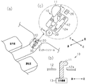
- (A) is a perspective view of the shift device
- (b) is a cross-sectional view taken along line AA of (a)
- (c) is an enlarged view of the shift device.
- the shift device is provided in a center console that divides a driver seat and a passenger seat.
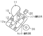
- This shift device includes a lever device 10, a parking switch 20, and a neutral switch 30.
- the lever device 10 includes a shift lever 11 and a shift panel 12 as shown in FIG.
- the shift panel 12 forms the same plane as the center console.
- the shift panel 12 is formed with a substantially H-shaped gate 12a.
- the tip of the shift lever 11 is outside the shift panel 12, and the base end of the shift lever 11 is connected to the support mechanism 13 inside the shift panel 12.
- the support mechanism 13 supports the shift lever 11 so that it can be tilted forward, backward, left, and right.
- the shaft of the shift lever 11 is disposed in the gate 12 a of the shift panel 12.
- the shift lever 11 can be tilted along the gate 12a.
- the left front end of the gate 12a is set to “shift up (+) position”, the left rear end is set to “shift down ( ⁇ ) position”, and the right front end is set to “reverse (R) position”.
- the right rear end is set to “drive (D) position”.
- An intermediate position between the “shift-up position” and the “shift-down position” is set to the “home (H) position”.
- the shift lever 11 reaches the shift-up position when operated in the forward direction from the home position.
- the shift lever 11 reaches the downshift position when operated backward from the home position.
- the shift lever 11 reaches the reverse position by being operated in the forward direction after being operated in the right direction from the home position.
- the shift lever 11 is operated in the right direction from the home position, and then is operated in the backward direction to reach the drive position.
- the shift lever 11 needs to be operated in a plurality of directions.
- the front-rear direction is the shift operation direction
- the left-right direction is the select operation direction.
- the drive position and the reverse position may be referred to as a travel start designated position that is selected when transmission of driving force to the drive wheels is started.
- the support mechanism 13 returns the shift lever 11 to the home position when the operating force on the shift lever 11 is released.
- the lever device 10 is a so-called momentary type.
- the parking switch 20 and the neutral switch 30 are constituted by push type switches.
- the parking switch 20 and the neutral switch 30 are disposed at a position sandwiching the lever device 10 therebetween.
- the neutral switch 30 is provided behind the lever device 10, and the parking switch 20 is provided in front of the lever device 10, and the neutral switch 30 is located on the front side of the driver, so that the driver is driving The neutral switch 30 can be easily operated. Since the parking switch 20 is further remote from the shift lever 11 for the driver, the parking switch 20 is operated more accurately during driving.
- Each of the parking switch 20 and the neutral switch 30 has an operation surface that forms the same surface as the surface of the center console.
- the operation surface of the neutral switch 30 is, for example, a circle, and the operation surface of the parking switch 20 is, for example, a quadrangle.
- the area of the operation surface of the neutral switch 30 is larger than that of the parking switch 20.
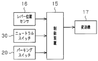
- the lever position sensor 16 detects the position of the shift lever 11 and supplies the detection result to the control device 15. Based on the detection result of the lever position sensor 16, the control device 15 determines that the shift lever 11 has been operated from the home position and the selected range designation position.
- Each of the parking switch 20 and the neutral switch 30 supplies an operation signal to the control device 15 when pressed.
- the control device 15 determines that the parking switch 20 or the neutral switch 30 has been operated based on the operation signal.
- the control device 15 outputs a control signal for requesting the transmission 17 to switch the shift range based on signals supplied from the lever position sensor 16, the parking switch 20, and the neutral switch 30.
- the shift range of the transmission 17 is switched by this control signal. Specifically, the control device 15 switches the transmission 17 to the D range through the control signal when the shift lever 11 is operated to the drive position.
- the transmission 17 in the D range switches the gear ratio according to the vehicle speed and the engine speed.
- the control device 15 switches the transmission 17 to the R range through the control signal.
- the control device 15 switches the transmission 17 to a higher gear ratio through the control signal.
- the control device 15 switches the transmission 17 to a lower gear ratio through the control signal.
- the shift lever 11 is operated to the shift-up position or the shift-down position when the transmission 17 is not in the D range, the control device 15 does not change the shift range of the transmission 17.
- the control device 15 switches the transmission 17 to a range (neutral (N) range) in which the driving force of the engine is not transmitted to the driving wheels.
- N neutral
- P range range
- the parking switch 20 or the neutral switch 30 corresponds to a switch. Examples of ranges in which transmission of driving force to the driving wheels of the vehicle is blocked are the N range and the P range.
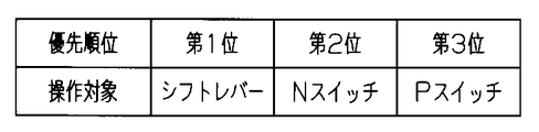
- the priority order of the shift lever 11, the neutral switch 30, and the parking switch 20 will be described. Specifically, the first priority is the shift lever 11, the second is the neutral switch 30, and the third is the parking switch 20.
- the control device 15 switches the range of the transmission 17 according to priority when two or three of the shift lever 11, the neutral switch 30 and the parking switch 20 are operated simultaneously. This improves the fail-safe performance when the parking switch 20 fails and when some of the shift lever 11, the neutral switch 30 and the parking switch 20 are operated.
- the shift lever 11 having a higher priority than the parking switch 20 is operated to the drive position or the like.
- the control device 15 enables the vehicle to travel by switching the transmission 17 to the D range.
- the control device 15 automatically turns on the transmission 17 based on the operation of the engine start switch for turning off the power of the vehicle. Switch to P range. Thus, no problem occurs even if the priority of the parking switch 20 is lower than that of the engine start switch.
- the neutral switch 30 is set to a higher priority than the parking switch 20, it is possible to reliably block the driving force from being transmitted to the driving wheels in an emergency.
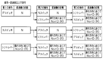
- the shift range of the transmission 17 is switched according to the chart of FIG. 4 from the viewpoint of fail-safe based on the above priority.
- the first to third operations in FIG. 4 are operations performed simultaneously.
- the parking switch 20 is operated as the first operation
- the shift lever 11 is operated in any of the first to third operations
- the range of the transmission 17 is switched according to the priority order.
- the control device 15 changes the range of the transmission 17 from the D range to the N range. Switch to. Even when the parking switch 20 is operated while the vehicle is traveling at a predetermined speed or higher, the transmission 17 does not make the drive system stationary, so that the vehicle is prevented from suddenly stopping.
- the range of the transmission 17 is switched according to the traveling direction of the vehicle. Specifically, when the shift lever 11 is operated to the drive position when the vehicle is moving forward at a predetermined speed or higher, the control device 15 maintains the transmission 17 in the D range or switches from the N range to the D range. When the vehicle is moving forward at a predetermined speed or higher and the shift lever 11 is operated to the reverse position, the control device 15 maintains the transmission 17 in the N range or switches from the D range to the N range from the viewpoint of fail-safe. .
- the control device 15 maintains the transmission 17 in the R range or switches from the N range to the R range. If the shift lever 11 is operated to the drive position when the vehicle is moving backward at a predetermined speed or higher, the control device 15 maintains the transmission 17 in the N range or switches from the R range to the N range from the viewpoint of fail-safe. .
- the shift lever 11 is included in the operation unit that is operated simultaneously, the shift lever 11 is prioritized over the parking switch 20 and the neutral switch 30, and the transmission 17 according to the traveling direction of the vehicle as described above.
- the range of can be switched.
- the control device 15 uses the operation signals from the parking switch 20 and the neutral switch 30 so that the operation of the shift lever 11 to the drive position or the reverse position has priority over the parking switch 20 and the neutral switch 30.
- the transmission 17 is controlled by giving priority to the detection signals representing the drive position and the reverse position from the lever position sensor 16.
- the range designation position (for example, the D position or the R position) of the shift lever 11 corresponding to the range of the transmission 17 that starts transmitting the driving force to the driving wheels of the vehicle is the original position (H position).
- H position To a position that is reached through movement in a plurality of directions (for example, two directions in the horizontal and forward directions, or two directions in the horizontal and subsequent directions).
- the driver In order to switch the transmission 17 to a range where transmission of driving force to the driving wheels of the vehicle is started, the driver is required to operate the shift lever 11 in a plurality of directions from the original position. For this reason, it is suppressed that shift lever 11 reaches D position etc. easily, and it is further suppressed that a vehicle starts a run.
- the direction of the operation performed by the driver to operate the parking switch 20 or the neutral switch 30 is required from the viewpoint of operability when the range for starting the transmission of the driving force to the drive wheels of the vehicle is designated. Less than a plurality of operating directions of the shift lever 11.
- the driver may press the parking switch 20 or the neutral switch 30 in a single operation direction.
- the parking switch 20 or the neutral switch 30 is associated with the range of the transmission 17 that cuts off the transmission of the driving force to the driving wheels of the vehicle. Therefore, even if the parking switch 20 or the neutral switch 30 is operated, the control device 15 only switches the transmission 17 to a range that cuts off the transmission of the driving force to the driving wheels of the vehicle, so that the vehicle does not travel. . Therefore, the operability of the parking switch 20 or the neutral switch 30 can be prioritized unlike the shift lever 11.
- the operation mode of the shift lever 11 and the parking switch 20 etc. suitable for the operation content of the vehicle accompanying the operation, the operability of the shift device can be improved.
- the neutral switch 30 is provided closer to the driver's seat than the parking switch 20.
- the user wants to switch the transmission 17 to the N range, it is necessary to selectively operate the neutral switch 30.
- a situation in which the driver's attention is excessively directed to both switches 20 and 30 is not preferable.
- a user who does not know the fail-safe function based on the priority order is more carefully operated on both switches 20 and 30 in order to accurately operate the parking switch 20 during traveling.
- the neutral switch 30 in front of the driver, the operation of the neutral switch 30 becomes easy especially during driving.
- the parking switch 20 further remote than the shift lever 11, more accurate operation of the parking switch 20 during traveling is possible.
- the parking switch 20 is operated in a stopped state, even if the parking switch 20 is disposed at a relatively remote position from the driver's seat, the user can operate it without any problem.
- Both switches 20 and 30 are located on opposite sides of the shift lever 11. That is, the parking switch 20 is in a position that has passed through the shift lever 11 as viewed from the driver. For this reason, the parking switch 20 can be operated more accurately during operation. Further, the neutral switch 30 is provided on the front side of the shift lever 11 as viewed from the driver. Therefore, when the neutral switch 30 is operated, the shift lever 11 is prevented from becoming a physical obstacle, and the neutral switch 30 is easily operated.
- the area of the operation surface of the neutral switch 30 is larger than that of the parking switch 20. Therefore, it becomes easier to operate the neutral switch 30.
- the shift-up position and the shift-down position are not travel start designated positions that are selected when transmission of driving force to the drive wheels is started. That is, when the transmission 17 is in a range (for example, N or P) in which the transmission of the driving force to the driving wheels is interrupted, the driver moves the shift lever 11 to the D position or the R position to move the transmission 17 to the driving wheels. Unless the vehicle is switched to the range (D, R) where transmission of the driving force is started, the vehicle does not travel.
- the transmission 17 cannot be switched to a range (D, R) where transmission of driving force to the driving wheel is started. Therefore, it is suppressed that the vehicle starts traveling.
- the parking switch 20 is provided near the reverse position, and the neutral switch 30 is provided near the drive position. For this reason, both switches 20 and 30 are arranged along the vehicle traveling direction with the shift lever 11 interposed therebetween. Thereby, the neutral switch 30 can be set to a position where it can be more easily operated, and the parking switch 20 can be set to a position where it is difficult to operate during driving.
- the neutral switch 30 is provided in such a manner that its operation surface forms the same surface as the surface of the center console.
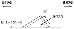
- the operation surface of the neutral switch 30 may be inclined with respect to the surface of the center console. Specifically, the operation surface of the neutral switch 30 is inclined so as to face the driver's seat. According to this configuration, the operation of the neutral switch 30 is further facilitated.
- the shape of the parking switch 20 is different, the switches 20 and 30 can be identified at a glance. Thereby, a more accurate operation becomes possible. Furthermore, even when an object is dropped on the operation surface of the neutral switch 30, the direction in which the object naturally falls due to gravity is different from the operation direction of the neutral switch 30, so that the neutral switch 30 is pushed by the falling of the object. Is suppressed.
- the parking switch 20 and the neutral switch 30 are located on the opposite sides of the lever device 10.
- the positions of the parking switch 20 and the neutral switch 30 are not limited to this.
- the parking switch 20 is installed on an extension line in the shift operation direction of the shift lever 11 as in the above embodiment.
- the neutral switch 30 is installed on the extension line in the select operation direction of the shift lever 11 and between the drive position and the reverse position. Also in this configuration, the switches 20 and 30 that are separated from each other can be easily identified and an accurate operation can be performed.
- parking switch 20 and the neutral switch 30 may be provided on the side of the shift lever 11.
- the parking switch 20 and the neutral switch 30 may be provided with a light emitter such as an LED (light emitting diode). Thereby, the visibility of the parking switch 20 and the neutral switch 30 can be improved. Further, the emission color may be changed between the parking switch 20 and the neutral switch 30. Thereby, the parking switch 20 and the neutral switch 30 can be operated more accurately.
- a light emitter such as an LED (light emitting diode).
- the parking switch 20 and the neutral switch 30 may be colored in different colors by printing or painting.
- the area of the operation surface of the neutral switch 30 is larger than that of the parking switch 20.
- the area of the operation surface of the parking switch 20 may be formed larger than that of the neutral switch 30.
- the area of the operation surface of both switches 20 and 30 may be the same.
- the shapes of the operation surfaces of both switches 20 and 30 may be the same.
- the neutral switch 30 and the parking switch 20 in the above embodiment may be configured with a single switch.
- the transmission 17 is switched to the N range in the same manner as when the neutral switch 30 is operated.
- the transmission 17 is switched to the P range in the same manner as when the parking switch 20 is operated. According to this configuration, the configuration of the shift device can be further simplified.
- At least one of the parking switch 20 and the neutral switch 30 may be provided on the operation knob of the shift lever 11.
- the difference in position between the switches 20 and 30 can be made clearer.
- the installation direction of the lever device 10 is not limited to the configuration of the embodiment described above, and may be installed vertically on an instrument panel, for example.
- the R position is provided above the vehicle with respect to the home position of the shift lever 11
- the D position is provided below the vehicle with respect to the home position of the shift lever 11.
- the parking switch 20 and the neutral switch 30 are push-type switches, but the type of the switch is not limited to this as long as it can be operated with fewer operation directions than the shift lever 11.
- a slide switch or a rotary switch may be used.
- two-way operation is required to operate the shift lever 11 from the home position to the drive position or the reverse position.
- the upshift position and the downshift position may be omitted.
Landscapes
- Engineering & Computer Science (AREA)
- General Engineering & Computer Science (AREA)
- Mechanical Engineering (AREA)
- Chemical & Material Sciences (AREA)
- Combustion & Propulsion (AREA)
- Transportation (AREA)
- Arrangement Or Mounting Of Control Devices For Change-Speed Gearing (AREA)
- Control Of Transmission Device (AREA)
Abstract
Description
第3の側面によれば、パーキングスイッチ及びニュートラルスイッチが離間して配置されるため、パーキングスイッチ及びニュートラルスイッチを識別し易い。よって、それらスイッチのより正確な操作が可能となる。
Claims (11)
- 操作態様の異なる操作レバー及びスイッチの操作を通じて車両の変速機を各シフトレンジに切り替える信号を出力するシフト切り替え装置において、
前記操作レバーが原位置から複数の方向に操作されてドライブ位置又はリバース位置に達した旨認識したとき、シフトレンジをドライブレンジ又はリバースレンジに切り替える信号を出力し、前記操作レバーは前記操作レバーに対する操作力が解除されたときには自動で前記原位置に復帰し、
前記スイッチとしてパーキングスイッチ及びニュートラルスイッチを備え、
前記パーキングスイッチが前記複数の方向より少ない方向に操作された旨認識したとき、シフトレンジをパーキングレンジに切り替える信号を出力し、
前記ニュートラルスイッチが前記複数の方向より少ない方向に操作された旨認識したとき、シフトレンジをニュートラルレンジに切り替える信号を出力するシフト切り替え装置。 - 請求項1に記載のシフト切り替え装置において、
前記ニュートラルスイッチは前記パーキングスイッチより運転席の近くに設けられるシフト切り替え装置。 - 請求項1又は2に記載のシフト切り替え装置において、
前記ニュートラルスイッチ及び前記パーキングスイッチ間の距離が、前記原位置の操作レバーと前記両スイッチの何れか一方との距離より長く設定されるシフト切り替え装置。 - 請求項1~3の何れか一項に記載のシフト切り替え装置において、
前記ニュートラルスイッチ及び前記パーキングスイッチは、前記操作レバーを挟んで互いに反対側に位置するシフト切り替え装置。 - 請求項1~3の何れか一項に記載のシフト切り替え装置において、
前記パーキングスイッチを前記操作レバーのシフト操作方向の延長線上に設置し、前記ニュートラルスイッチを前記操作レバーのセレクト操作方向の延長線上、かつ前記ドライブ位置及び前記リバース位置間に設置したシフト切り替え装置。 - 請求項1~5の何れか一項に記載のシフト切り替え装置において、
前記両スイッチにおける操作面の形状又は面積を異ならせたシフト切り替え装置。 - 請求項1~4、6の何れか一項に記載のシフト切り替え装置において、
前記パーキングスイッチは前記リバース位置側に設けられるとともに、前記ニュートラルスイッチは前記ドライブ位置側に設けられるシフト切り替え装置。 - 請求項1~7の何れか一項に記載のシフト切り替え装置において、
前記パーキングスイッチ及びニュートラルスイッチに、それらの操作面をそれぞれ異なる色で光らせる発光体を設けたシフト切り替え装置。 - 駆動輪を有する車両とともに用いられ、前記駆動輪への駆動力の伝達を遮断するレンジと前記駆動輪に駆動力を伝達するレンジとを含む複数のレンジを有する変速機に対して各シフトレンジに切り替える信号を出力するシフト切り替え装置であって、
複数のレンジ指定位置を有するゲートを含むシフトパネルと
前記ゲートに沿って移動可能なシフトレバーであって、当該シフトレバーに対する操作力が解除されたときに自動で前記原位置に復帰する前記シフトレバーと、
前記シフトレバーから離間して配置され、前記駆動輪への駆動力の伝達を遮断するレンジに対応付けられたプッシュ式操作部材とを備え、
前記ゲートの前記複数のレンジ指定位置は、駆動力が伝達されていない駆動輪へ駆動力の伝達を開始するときに選択される走行開始指定位置を含み、当該走行開始指定位置は、前記シフトレバーを前記原位置から2以上の方向への移動を経て到達する位置にある、シフト切り替え装置。 - 請求項9に記載のシフト切り替え装置において、
前記走行開始指定位置は、ドライブ位置及びリバース位置であり、
前記プッシュ式操作部材は、パーキングスイッチと、当該パーキングスイッチよりも運転席の近くに配置されたニュートラルスイッチとを含むシフト切り替え装置。 - 請求項9に記載のシフト切り替え装置において、
前記ゲートの前記複数のレンジ指定位置は、前記変速機の変速比を変更するときに選択される変速比変更位置を更に含み、
前記変速比変更位置は、前記シフトレバーを前記原位置から1方向への移動を経て到達する位置にある、シフト切り替え装置。
Priority Applications (6)
| Application Number | Priority Date | Filing Date | Title |
|---|---|---|---|
| CN201180071760.6A CN103889764A (zh) | 2011-06-23 | 2011-06-23 | 挡位切换装置 |
| DE112011105366.5T DE112011105366T5 (de) | 2011-06-23 | 2011-06-23 | Schaltungsumschaltvorrichtung |
| PCT/JP2011/064462 WO2012176316A1 (ja) | 2011-06-23 | 2011-06-23 | シフト切り替え装置 |
| BR112013032718A BR112013032718A2 (pt) | 2011-06-23 | 2011-06-23 | dispositivo para mudança de marchas |
| JP2013521386A JP5842001B2 (ja) | 2011-06-23 | 2011-06-23 | シフト切り替え装置 |
| US14/126,243 US9234575B2 (en) | 2011-06-23 | 2011-06-23 | Shift switching device |
Applications Claiming Priority (1)
| Application Number | Priority Date | Filing Date | Title |
|---|---|---|---|
| PCT/JP2011/064462 WO2012176316A1 (ja) | 2011-06-23 | 2011-06-23 | シフト切り替え装置 |
Publications (1)
| Publication Number | Publication Date |
|---|---|
| WO2012176316A1 true WO2012176316A1 (ja) | 2012-12-27 |
Family
ID=47422191
Family Applications (1)
| Application Number | Title | Priority Date | Filing Date |
|---|---|---|---|
| PCT/JP2011/064462 Ceased WO2012176316A1 (ja) | 2011-06-23 | 2011-06-23 | シフト切り替え装置 |
Country Status (6)
| Country | Link |
|---|---|
| US (1) | US9234575B2 (ja) |
| JP (1) | JP5842001B2 (ja) |
| CN (1) | CN103889764A (ja) |
| BR (1) | BR112013032718A2 (ja) |
| DE (1) | DE112011105366T5 (ja) |
| WO (1) | WO2012176316A1 (ja) |
Cited By (4)
| Publication number | Priority date | Publication date | Assignee | Title |
|---|---|---|---|---|
| US9316304B2 (en) | 2013-11-18 | 2016-04-19 | Hyundai Motor Company | Shifting apparatus for vehicle |
| JP2016094059A (ja) * | 2014-11-13 | 2016-05-26 | マツダ株式会社 | 車両用シフト装置 |
| KR101906443B1 (ko) | 2014-03-31 | 2018-10-11 | 에스엘 주식회사 | 차량용 변속 장치 |
| US20250230870A1 (en) * | 2022-04-07 | 2025-07-17 | Nissan Motor Co., Ltd. | Control method for vehicle and control device for vehicle |
Families Citing this family (5)
| Publication number | Priority date | Publication date | Assignee | Title |
|---|---|---|---|---|
| KR101575477B1 (ko) * | 2014-05-23 | 2015-12-07 | 현대자동차주식회사 | 인사이드 미러의 버튼 심볼 제어 방법 |
| JP6354795B2 (ja) * | 2016-06-22 | 2018-07-11 | トヨタ自動車株式会社 | 車両の制御装置 |
| CN109654217B (zh) * | 2018-11-14 | 2021-01-12 | 宝沃汽车(中国)有限公司 | 换挡控制系统、车辆及换挡控制方法 |
| JP7554545B2 (ja) * | 2019-12-25 | 2024-09-20 | 株式会社ユーシン | シフト装置 |
| JP7588501B2 (ja) | 2020-12-04 | 2024-11-22 | 水口 祐介 | 樹木加工品製造方法及び樹木加工品 |
Citations (4)
| Publication number | Priority date | Publication date | Assignee | Title |
|---|---|---|---|---|
| JPS57178085U (ja) * | 1981-05-08 | 1982-11-11 | ||
| JPH0665051U (ja) * | 1993-02-24 | 1994-09-13 | 株式会社東海理化電機製作所 | 自動変速機用操作スイッチ |
| JP2003034159A (ja) * | 2001-07-19 | 2003-02-04 | Toyota Motor Corp | 変速機のシフト制御装置 |
| JP2005007993A (ja) * | 2003-06-18 | 2005-01-13 | Toyota Motor Corp | 変速機のシフト操作装置 |
Family Cites Families (11)
| Publication number | Priority date | Publication date | Assignee | Title |
|---|---|---|---|---|
| JPS57178085A (en) | 1981-04-28 | 1982-11-02 | Kogyo Gijutsuin | Apparatus for attaching interior pipe in riser |
| JP3285619B2 (ja) | 1992-08-20 | 2002-05-27 | 株式会社資生堂 | 皮膚外用剤 |
| DE10126132B4 (de) * | 2000-05-31 | 2013-02-07 | Kabushiki Kaisha Tokai Rika Denki Seisakusho | Schaltvorrichtung für Fahrzeuge |
| JP2002286131A (ja) | 2001-03-26 | 2002-10-03 | Toyota Motor Corp | シフト制御装置 |
| JP4336330B2 (ja) * | 2005-06-15 | 2009-09-30 | 本田技研工業株式会社 | シフト表示装置 |
| JP4681482B2 (ja) | 2006-03-27 | 2011-05-11 | 本田技研工業株式会社 | 自動変速機のシフト操作装置 |
| JP4831004B2 (ja) * | 2007-07-23 | 2011-12-07 | トヨタ自動車株式会社 | シフト制御装置 |
| JP2009058085A (ja) | 2007-08-31 | 2009-03-19 | Toyota Motor Corp | シフト制御装置 |
| JP4305556B2 (ja) | 2007-11-28 | 2009-07-29 | トヨタ自動車株式会社 | 車両の制御装置 |
| JP5146831B2 (ja) | 2008-10-24 | 2013-02-20 | スズキ株式会社 | シフトセレクトシステム |
| CN102667259B (zh) * | 2009-12-22 | 2015-04-08 | 丰田自动车株式会社 | 车辆用换档控制装置 |
-
2011
- 2011-06-23 DE DE112011105366.5T patent/DE112011105366T5/de not_active Withdrawn
- 2011-06-23 WO PCT/JP2011/064462 patent/WO2012176316A1/ja not_active Ceased
- 2011-06-23 US US14/126,243 patent/US9234575B2/en not_active Expired - Fee Related
- 2011-06-23 BR BR112013032718A patent/BR112013032718A2/pt not_active IP Right Cessation
- 2011-06-23 CN CN201180071760.6A patent/CN103889764A/zh active Pending
- 2011-06-23 JP JP2013521386A patent/JP5842001B2/ja not_active Expired - Fee Related
Patent Citations (4)
| Publication number | Priority date | Publication date | Assignee | Title |
|---|---|---|---|---|
| JPS57178085U (ja) * | 1981-05-08 | 1982-11-11 | ||
| JPH0665051U (ja) * | 1993-02-24 | 1994-09-13 | 株式会社東海理化電機製作所 | 自動変速機用操作スイッチ |
| JP2003034159A (ja) * | 2001-07-19 | 2003-02-04 | Toyota Motor Corp | 変速機のシフト制御装置 |
| JP2005007993A (ja) * | 2003-06-18 | 2005-01-13 | Toyota Motor Corp | 変速機のシフト操作装置 |
Cited By (5)
| Publication number | Priority date | Publication date | Assignee | Title |
|---|---|---|---|---|
| US9316304B2 (en) | 2013-11-18 | 2016-04-19 | Hyundai Motor Company | Shifting apparatus for vehicle |
| KR101906443B1 (ko) | 2014-03-31 | 2018-10-11 | 에스엘 주식회사 | 차량용 변속 장치 |
| JP2016094059A (ja) * | 2014-11-13 | 2016-05-26 | マツダ株式会社 | 車両用シフト装置 |
| US20250230870A1 (en) * | 2022-04-07 | 2025-07-17 | Nissan Motor Co., Ltd. | Control method for vehicle and control device for vehicle |
| US12410862B2 (en) * | 2022-04-07 | 2025-09-09 | Nissan Motor Co., Ltd. | Control method for vehicle and control device for vehicle |
Also Published As
| Publication number | Publication date |
|---|---|
| US9234575B2 (en) | 2016-01-12 |
| US20140144272A1 (en) | 2014-05-29 |
| DE112011105366T5 (de) | 2014-05-15 |
| CN103889764A (zh) | 2014-06-25 |
| JP5842001B2 (ja) | 2016-01-13 |
| JPWO2012176316A1 (ja) | 2015-02-23 |
| BR112013032718A2 (pt) | 2017-01-24 |
Similar Documents
| Publication | Publication Date | Title |
|---|---|---|
| JP5842001B2 (ja) | シフト切り替え装置 | |
| CN103946593B (zh) | 换挡器组件 | |
| JP4009405B2 (ja) | 選択装置を備えた自動車 | |
| US7603924B2 (en) | Control device for automatic transmission | |
| KR101575414B1 (ko) | 차량의 변속 장치 | |
| JP6052214B2 (ja) | 車両用シフト装置 | |
| US6621176B1 (en) | Input device for use in vehicles for inputting settings pertaining to driver's intention of acceleration and deceleration | |
| US20190375392A1 (en) | Device and method for controlling a vehicle and vehicle | |
| KR102557103B1 (ko) | 자동 기어박스의 원-터치 제어 장치 | |
| WO2016042949A1 (ja) | 車両用シフタ装置 | |
| KR20200081764A (ko) | 차량용 변속 장치 | |
| JP2005504685A (ja) | 自動シフト装置の運転状態を調節するための信号発生器 | |
| US20120001747A1 (en) | Electronic drive selector assembly systems and methods | |
| KR20160147462A (ko) | 차량용 변속 장치 | |
| JP6060962B2 (ja) | 車両用シフト装置 | |
| JP6610634B2 (ja) | 車両用シフタ装置 | |
| JP5880397B2 (ja) | 車両のシフト装置 | |
| JP6003785B2 (ja) | 車両のシフト装置 | |
| JPH1016594A (ja) | 自動変速操作装置 | |
| JP5844513B2 (ja) | シフト装置 | |
| JP2006273208A (ja) | シフトレバー装置 | |
| JP4814629B2 (ja) | シフト装置 | |
| JP3643256B2 (ja) | 自動変速機のシフトレバー装置 | |
| KR101432993B1 (ko) | 차량용 자동변속기 시프트 레버 장치 | |
| CN101846174A (zh) | 用于车辆变速器换挡的手动操作装置 |
Legal Events
| Date | Code | Title | Description |
|---|---|---|---|
| 121 | Ep: the epo has been informed by wipo that ep was designated in this application |
Ref document number: 11868048 Country of ref document: EP Kind code of ref document: A1 |
|
| DPE1 | Request for preliminary examination filed after expiration of 19th month from priority date (pct application filed from 20040101) | ||
| ENP | Entry into the national phase |
Ref document number: 2013521386 Country of ref document: JP Kind code of ref document: A |
|
| WWE | Wipo information: entry into national phase |
Ref document number: 14126243 Country of ref document: US |
|
| WWE | Wipo information: entry into national phase |
Ref document number: 1120111053665 Country of ref document: DE Ref document number: 112011105366 Country of ref document: DE |
|
| NENP | Non-entry into the national phase |
Ref country code: DE Effective date: 20131223 |
|
| REG | Reference to national code |
Ref country code: BR Ref legal event code: B01A Ref document number: 112013032718 Country of ref document: BR |
|
| 122 | Ep: pct application non-entry in european phase |
Ref document number: 11868048 Country of ref document: EP Kind code of ref document: A1 |
|
| ENP | Entry into the national phase |
Ref document number: 112013032718 Country of ref document: BR Kind code of ref document: A2 Effective date: 20131219 |