WO2012172897A1 - 冷蔵庫 - Google Patents
冷蔵庫 Download PDFInfo
- Publication number
- WO2012172897A1 WO2012172897A1 PCT/JP2012/062167 JP2012062167W WO2012172897A1 WO 2012172897 A1 WO2012172897 A1 WO 2012172897A1 JP 2012062167 W JP2012062167 W JP 2012062167W WO 2012172897 A1 WO2012172897 A1 WO 2012172897A1
- Authority
- WO
- WIPO (PCT)
- Prior art keywords
- box
- plate portion
- inner plate
- heat insulation
- sheet member
- Prior art date
Links
Images


Classifications
-
- F—MECHANICAL ENGINEERING; LIGHTING; HEATING; WEAPONS; BLASTING
- F25—REFRIGERATION OR COOLING; COMBINED HEATING AND REFRIGERATION SYSTEMS; HEAT PUMP SYSTEMS; MANUFACTURE OR STORAGE OF ICE; LIQUEFACTION SOLIDIFICATION OF GASES
- F25D—REFRIGERATORS; COLD ROOMS; ICE-BOXES; COOLING OR FREEZING APPARATUS NOT OTHERWISE PROVIDED FOR
- F25D23/00—General constructional features
- F25D23/06—Walls
- F25D23/062—Walls defining a cabinet
- F25D23/063—Walls defining a cabinet formed by an assembly of panels
-
- F—MECHANICAL ENGINEERING; LIGHTING; HEATING; WEAPONS; BLASTING
- F25—REFRIGERATION OR COOLING; COMBINED HEATING AND REFRIGERATION SYSTEMS; HEAT PUMP SYSTEMS; MANUFACTURE OR STORAGE OF ICE; LIQUEFACTION SOLIDIFICATION OF GASES
- F25D—REFRIGERATORS; COLD ROOMS; ICE-BOXES; COOLING OR FREEZING APPARATUS NOT OTHERWISE PROVIDED FOR
- F25D23/00—General constructional features
- F25D23/06—Walls
- F25D23/065—Details
- F25D23/067—Supporting elements
Definitions
- Embodiment of this invention is related with a refrigerator.
- a heat insulating box of a refrigerator has a vacuum heat insulating panel between an inner box and an outer box.
- the inner box is formed of an integrally molded product formed entirely by injection molding or vacuum molding.
- the inner box is formed of a single integrally molded product by molding, so that there is a problem that a large mold is required and manufacturing costs are high.
- the refrigerator according to the embodiment includes a heat insulating box having an outer box, an inner box provided inside the outer box, and a vacuum heat insulating panel provided between the outer box and the inner box, At least a part of the inner box was composed of a flat sheet member.
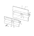
- the perspective view which looked at the heat insulation box of the refrigerator by a first embodiment from the lower part The perspective view which looked at the heat insulation box from the upper part Perspective view of the refrigerator as seen from above Transverse plan view of heat insulation box Exploded perspective view of left heat insulation wall
- a perspective view of the upper inner plate viewed from below The perspective view which looked at the lower inner plate part from the upper part Enlarged view of the portion indicated by the symbol K in FIG.
- FIG. 9 equivalent Longitudinal side view showing the shelf support part Vertical side view showing the shelf board support portion at a position different from FIG.
- FIG. 1 equivalent diagram according to the third embodiment Figure equivalent to FIG.
- the refrigerator 1 by 1st embodiment is demonstrated with reference to FIGS.
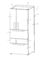
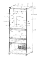
- the refrigerator 1 shown in FIG. 3 is mainly composed of a heat insulating box 2.
- the heat insulation box 2 has an opening formed on one surface.
- the said opening side be the heat insulation box 2, ie, the front side of the refrigerator 1, with respect to the heat insulation box 2.
- the horizontal direction be the left-right direction of the heat insulation box 2, ie, the refrigerator 1, with respect to the paper surface of FIG.
- a rotating left rotating door 3 and a right rotating door 4 and a plurality of pull-out doors 5 to 8 are provided on the front side of the heat insulating box 2.
- Each of the doors 3 to 8 has a heat insulating material (not shown) inside.
- the heat insulation box 2 has hinge portions 3a and 3b and hinge portions 4a and 4b.
- the left rotating door 3 is rotatably supported by a pair of upper and lower hinge portions 3a and 3b.
- the right rotating door 4 is rotatably supported by a pair of upper and lower 4a, 4b.
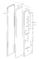
- the heat insulation box 2 is configured by connecting unit heat insulation walls 9 to 13 divided into a plurality of parts. That is, the heat insulating box 2 is configured by connecting the left heat insulating wall 9, the right heat insulating wall 10, the upper heat insulating wall 11, the lower heat insulating wall 12, and the back heat insulating wall 13.
- the heat insulation box 2 has transverse beam members 51, 52, 53 and a longitudinal beam member 54.
- the cross beam members 51, 52, 53 are provided on the opening side of the heat insulating box 2.
- the horizontal beam members 51, 52, 53 connect the left and right edges of the heat insulating box 2, that is, the left heat insulating wall 9 and the right heat insulating wall 10 in the horizontal direction.
- the vertical beam member 54 is in the middle of the horizontal beam members 52 and 53 in the left-right direction, and connects the horizontal beam members 52 and 53 in the vertical direction.
- a first partition wall 55 for partitioning the storage chamber is provided on the rear side of the horizontal beam member 52.
- a second partition wall 56 for partitioning the storage chamber is provided on the rear side of the horizontal beam member 52.
- the heat insulation box 2 has a refrigeration room 57, a vegetable room 58, a small freezing room 59, an ice making room 60, and a freezing room 61 as storage rooms.
- the refrigerator compartment 57 is formed above the first partition wall 55.
- the vegetable compartment 58 is formed between the first partition wall 55 and the second partition wall 56.
- the small freezer compartment 59 is formed on the right side of the vertical beam member 54 between the horizontal beam member 52 and the horizontal beam member 53.
- the ice making chamber 60 is formed between the horizontal beam member 52 and the horizontal beam member 53 and on the left side of the vertical beam member 54, that is, on the left side of the small freezing chamber 59.
- the freezer compartment 61 is formed below the cross beam member 53.
- the front opening of the refrigerator compartment 57 is opened and closed by the rotating doors 3 and 4.
- the front opening of the vegetable compartment 58 is opened and closed by the pull-out door 5.
- the drawer-type door 5 integrally has a vegetable container (not shown) on the back side.
- the opening on the front surface of the small freezer compartment 59 is opened and closed by the drawer door 6.
- the drawer-type door 6 integrally has a frozen product storage container (not shown) on the back side thereof.
- the opening on the front surface of the ice making chamber 60 is opened and closed by a pull-out door 7.
- the drawer-type door 7 has an ice receiving container (not shown) integrally on the back side thereof.
- the front opening of the freezer compartment 61 is opened and closed by a pull-out door 8.
- the drawer-type door 8 integrally has a frozen product storage container (not shown) on the back side thereof.
- the second partition wall 56 shown in FIGS. 1 and 2 has a heat insulating material such as polystyrene foam or urethane foam inside. Thereby, the second partition wall 56 partitions the small freezing room 59 and ice making room 60 having a large storage temperature difference from the vegetable room 58 in an adiabatic manner.
- the first partition wall 55 is made of, for example, a synthetic resin plate. Thereby, the 1st partition wall 55 has partitioned the refrigerator compartment 57 and the vegetable compartment 58 which are not so large in storage temperature difference.
- the outer box 14 constitutes the entire outline of the heat insulating box 2.
- the outer box 14 is configured by combining a plurality of outer plate parts. That is, the outer box 14 is configured by combining the left outer plate portion 14A, the right outer plate portion 14B, the upper outer plate portion 14C, the lower outer plate portion 14D, and the rear outer plate portion 14E.
- the left outer plate portion 14 ⁇ / b> A constitutes the left outer surface of the outer box 14.
- the right outer plate portion 14 ⁇ / b> B constitutes the right outer surface of the outer box 14.
- the upper outer plate portion 14 ⁇ / b> C constitutes the upper outer surface of the outer box 14.
- the lower outer plate portion 14D constitutes the lower outer surface of the outer box 14.
- the rear outer plate portion 14E constitutes the rear outer surface of the outer box 14.
- Each of the outer plate portions 14A to 14E is made of a steel plate.
- the left outer plate portion 14A and the right outer plate portion 14B are configured symmetrically.
- the inner box 15 constitutes the inner surface of the heat insulating box 2.
- the inner box 15 is configured by combining a plurality of inner plate portions. That is, the inner box 15 is configured by combining the left inner plate portion 15A, the right inner plate portion 15B, the upper inner plate portion 15C, the lower inner plate portion 15D, and the back inner plate portion 15E.
- the left inner plate portion 15 ⁇ / b> A constitutes the left inner surface of the inner box 15.
- the right inner plate portion 15 ⁇ / b> B constitutes the right inner surface of the inner box 15.
- the upper inner plate portion 15 ⁇ / b> C constitutes the upper inner surface of the inner box 15.
- the lower inner plate portion 15 ⁇ / b> D constitutes the lower inner surface of the inner box 15.
- the back inner plate portion 15 ⁇ / b> E constitutes the back inner surface of the inner box 15.
- the left inner plate portion 15A and the right inner plate portion 15B are configured symmetrically.
- the left inner plate portion 15A and the right inner plate portion 15B are made of, for example, a synthetic resin such as ABS resin, and are configured by a flat sheet member Sa.
- the sheet member Sa is shown in a form in which a fixture 26, a shelf support 30, guide rail attachments 33 and 34, and partition wall supports 35 and 36, which will be described later, are attached in advance.
- the upper inner plate portion 15C has an L-shaped portion 17 integrally as shown in FIG.
- the L-shaped portion 17 functions as a bent portion and bulges into the interior, that is, the inside of the heat insulating box 2.
- the upper inner plate portion 15C is configured by an integrally molded product Ia made of a synthetic resin such as an olefin resin.
- the lower inner plate portion 15D integrally includes a drainage receiving portion 18 as shown in FIG.
- the drainage receiving part 18 functions as a bent part.
- the lower inner plate portion 15D is composed of an integrally molded product Ib made of synthetic resin. These integrally molded products Ia and Ib are formed by injection molding or vacuum molding.
- the back inner plate portion 15E is composed of a flat sheet member Sb made of synthetic resin.
- the sheet member Sa and the sheet member Sb can be manufactured by extrusion molding, rolling molding, or the like without using a specially shaped mold. Further, a commercially available flat sheet member may be used.
- a vacuum heat insulation panel 16 is provided between the outer box 14 and the inner box 15.
- the vacuum heat insulation panel 16 is comprised from the plate-shaped unit panel divided
- the left unit panel 16A is configured such that the base material 19 is accommodated in a package 20, and the inside thereof is sealed under reduced pressure by evacuation.
- the base material 19 is formed into a plate shape by compression-curing a laminated material of inorganic fibers such as glass wool.
- the envelope 20 includes a metal layer such as an aluminum vapor deposition layer or an aluminum foil layer.
- Each unit panel is generally called a vacuum insulation panel.
- the left heat insulating wall 9 has a left unit panel 16A disposed between the left outer plate portion 14A and the left inner plate portion 15A, and these three members are bonded with an adhesive to form a unit heat insulating wall. It is configured.
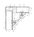
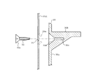
- the front end portions of the outer box 14 and the inner box 15, that is, the front end portions of the left heat insulating wall 9 and the right heat insulating wall 10 are connected by a front end connecting member 21 as shown in FIG. 8. That is, when viewing the front end portion of the left heat insulating wall 9, the front end portions of the left outer plate portion 14 ⁇ / b> A and the left inner plate portion 15 ⁇ / b> A are connected to each other by the front end connecting member 21.
- the front end connecting member 21 is made of synthetic resin and has heat insulating performance. In this case, since the front end portion of the left heat insulating wall 9 and the front end portion of the right heat insulating wall 10 are bilaterally symmetric, the configuration of the front end portion of the left heat insulating wall 9 will be described.
- the front end portions of the left outer plate portion 14A and the left inner plate portion 15A extend forward from the front end portion of the left unit panel 16A, respectively.
- the left outer plate portion 14A is bent toward the left inner plate portion 15A at the front end portion, and extends to the central portion in the thickness direction of the left unit panel 16A.
- a bent portion of the front end of the left outer plate portion 14A is referred to as a bent portion 14Aa.
- the bent portion 14Aa does not enter the inside of the heat insulating box 2, that is, the storage chamber side. That is, the bent portion 14Aa does not extend to the right side than the left inner plate portion 15A.
- the heat outside the heat insulating box 2 is suppressed from flowing into the storage chamber through the outer box 14, in this case, the left outer plate portion 14 ⁇ / b> A.
- a heat insulating material composed of, for example, soft tape 22 is provided in the internal space formed by the front end of the left unit panel 16A, the front end portion inner surface of the left outer plate portion 14A, and the inner surface of the front end connecting member 21, a heat insulating material composed of, for example, soft tape 22 is provided. ing. In addition, it may replace with the soft tape 22 and may comprise a polystyrene foam.
- the right heat insulating wall 10 has the same configuration as the left heat insulating wall 9 and is configured to be bilaterally symmetric.
- the upper heat insulating wall 11 has an upper unit panel 16C between the upper outer plate portion 14C and the upper inner plate portion 15C.
- the upper unit panel 16C is bonded to the upper inner plate portion 15C.
- a foamed urethane 24 is filled between the upper unit panel 16C and the upper outer plate portion 14C.
- the upper outer plate portion 14C has an L-shaped portion 17a corresponding to the L-shaped portion 17 of the upper inner plate portion 15C.
- the upper heat insulating wall 11 has a concave portion 11a at the rear.
- the space behind the concave portion 11a functions as the machine room 11b.
- the machine room 11b is provided with a compressor, a condenser, etc. (not shown) constituting the refrigeration cycle. As shown in FIG. 3, the machine room 11b is closed by a machine room cover 11c.
- the dimension between the upper unit panel 16C and the upper outer plate part 14C that is, the thickness dimension of the portion filled with the urethane foam 24 is smaller than the thickness of the upper unit panel 16C, and It is set smaller than the outer diameter of the piping of the refrigeration cycle, for example, the suction pipe. Thereby, the usage-amount of the urethane foam 24 is reduced.
- the piping of the refrigeration cycle when the piping of the refrigeration cycle is routed, the piping may be passed in the front-rear direction at the upper left corner of the heat insulation box 2.
- the corner portion is surrounded by the left end surface of the upper unit panel 16C, the upper end surface of the left unit panel 16A, the left end edge portion of the upper outer plate portion 14C, and the upper end edge portion of the left outer plate portion 14A. Show the space.
- the left end portion of the upper outer plate portion 14C is connected to the left outer plate portion 14A while being separated from the upper surface of the upper unit panel 16C.
- the right end portion of the upper outer plate portion 14C is similarly connected to the right outer plate portion 14B at a distance from the upper surface of the upper unit panel 16C.
- the upper inner plate portion 15C has a connecting portion 15C1.
- the connecting portion 15C1 is provided at the left and right edges of the upper inner plate portion 15C.
- the connecting portion 15C1 connects the upper inner plate portion 15C and the left inner plate portion 15A. In this case, the distal end portion of the connecting portion 15C1 is connected to the left inner plate portion 15A by a connecting tool (not shown).
- the connecting portion 15C1 has a rib 15C2.
- the rib 15C2 is on the inner side of the distal end portion of the connecting portion 15C1, that is, on the urethane foam 24 side, and protrudes upward substantially parallel to the left inner plate portion 15A.
- a soft tape 23 is inserted between the rib 15C2 and the left inner plate portion 15A as a heat insulating material leakage preventing member. The soft tape 23 suppresses leakage of the foamed urethane 24 when the foamed urethane 24 is filled.
- the lower heat insulating wall 12 has a lower unit panel (not shown) between the lower outer plate portion 14D and the lower inner plate portion 15D.
- the lower unit panel is bonded to the lower outer plate portion 14D and the lower inner plate portion 15D.
- the unit heat insulation wall is comprised.
- the lower heat insulating wall 12 may be configured by adhering the lower inner plate portion 15D and the lower unit panel and filling and solidifying urethane foam between the lower unit panel and the lower outer plate portion 14D. good.
- the lowermost part of the drain receiving part 18 communicates with the outside of the heat insulating box 2.
- the back side heat insulation wall 13 also arrange
- the integrally molded products Ia and Ib made of olefin resin are surface processed so that the bonding surface with the unit panel becomes a rough surface, so that the unit panel And improved adhesion.
- the sheet members Sa and Sb are made of ABS resin, and thus have good adhesion to the unit panel.
- connection between the left heat insulating wall 9 and the back heat insulating wall 13 will be described with reference to FIGS.
- the left heat insulating wall 9 and the back heat insulating wall 13 are connected by a connecting plate 25 for sheet members, a fixture 26 and the like.
- the sheet member connection plate 25 functions as a sheet member connection member
- the fixture 26 functions as a first protrusion.
- the structure of the connection part of the left side heat insulation wall 9 and the back side heat insulation wall 13 is demonstrated.
- the structure of the connection part of the right side heat insulation wall 10 and the back side heat insulation wall 13 is comprised similarly to the structure of the connection part of the left side heat insulation wall 9 and the back side heat insulation wall 13 except being left-right symmetric. ing.
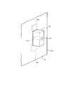
- the fixtures 26 are provided on the left heat insulating wall 9 and the back heat insulating wall 13 so as to protrude to the inside of the warehouse. Since the structure of the fixing tool 26 and the structure of the mounting portion of the fixing tool 26 are common to the left heat insulating wall 9 and the back heat insulating wall 13, the fixing tool 26 of the left heat insulating wall 9 will be described below.
- the fixture 26 is made of a synthetic resin such as ABS resin, and is formed in a rectangular parallelepiped shape that is long in the vertical direction.
- the fixture 26 has a hook-shaped portion 26a and a screw hole portion 26c.
- the hook-shaped portion 26a is provided on the one end side of the rectangular parallelepiped shape of the fixture 26 so as to protrude in the vertical direction.
- the screw hole portion 26c is a female screw formed from the other end face of the rectangular parallelepiped shape of the fixture 26 toward the one end portion side.
- the fixture 26 When assembling the left heat insulating wall 9, first, the fixture 26 is bonded to the left unit panel 16A.
- the left inner plate portion 15A that is, the sealing member Sa has a slightly vertically long rectangular hole portion 15u formed in advance.
- the fixture 26 After the fixture 26 is bonded to the left unit panel 16A, it is inserted into the hole 15u from the back side of the left inner plate part 15A, that is, the left unit panel 16A side, to the front side, that is, the storage chamber side.
- an adhesive is provided between the left unit panel 16A and the left inner plate portion 15A. Therefore, the left unit panel 16A and the left inner plate portion 15A are bonded.
- the fixture 26 is fixed by sandwiching the hook-shaped portion 26a between the left inner plate portion 15A and the left unit panel 16A.
- the fixture 26 is attached to the left heat insulating wall 9 and protrudes into the inner box 15.
- the fixing tool 26 is provided in the upper and lower two or more places in each adjacent edge part in the left side heat insulation wall 9 and the back side heat insulation wall 13.
- the connecting plate for sheet member 25 is formed to have substantially the same length as the left inner plate portion 15A in the vertical direction.
- the sheet member connecting plate 25 has a recessed portion 25 a that is recessed in an L shape at both end edges in the horizontal direction.
- the recessed portions 25a correspond to the fixtures 26, respectively.
- a screw insertion hole 25b is formed in the recess 25a.
- a screw 27 is passed through the screw insertion hole 25b. The screw 27 is screwed into the screw hole portion 26 c of the fixture 26.
- the sheet member connection plates 25 are provided at the corners on both sides of the refrigerator compartment 57, the vegetable compartment 58, the small freezer compartment 59, the ice making room 60, and the freezer compartment 61.
- a polystyrene foam 28 and a soft tape 29 are provided in a space on the back side of the sheet member connecting plate 25, that is, a space surrounded by the sheet member connecting plate 25, the left inner plate portion 15A, and the inner inner plate portion 15E. ing. The polystyrene foam 28 and the soft tape 29 function as a heat insulating member.
- shelf support members 30 are provided on the left heat insulating wall 9 and the right heat insulating wall 10.
- the shelf support 30 provided on the right heat insulation wall 10 is configured in the same manner as the shelf support 30 provided on the left heat insulation wall 9.
- the shelf board support 30 is a separate part from the inner plate portions 15A and 15B made of the sheet member Sa, and is made of synthetic resin such as ABS resin.
- the shelf board support 30 integrally includes a main body 30a, a shelf board support 30b, and a screw hole 30c.
- the main body 30a is formed in a rectangular plate shape that is long in the vertical direction.
- the shelf support part 30b is provided on one surface of the main body part 30a and protrudes to the inside of the cabinet. In this case, the shelf board support part 30b functions as a 2nd protrusion part.
- Three shelf support parts 30b are provided side by side in the vertical direction with respect to the main body part 30a.
- the screw hole portion 30c is provided at a position corresponding to the shelf board support portion 30b of the main body portion 30a. Each screw hole portion 30c is formed through the main body portion 30a from the surface opposite to the shelf plate support portion 30b toward the shelf plate support portion 30b side in the main body portion 30a, and further through the shelf plate support portion 30b halfway. Has been.
- the screw hole 30c has a female screw formed inside.
- the screw hole portion 30c functions as a fastening member engaging portion.
- a so-called countersunk-shaped counterbore 30d that opens in a conical shape is formed at the opening peripheral edge of the screw hole 30c.
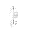
- the left inner plate portion 15A has a screw insertion hole portion 31, as shown in FIG.
- the screw insertion hole 31 functions as a fastening member insertion hole.
- Three screw insertion holes 31 are provided in the vertical direction in a portion corresponding to the refrigerator compartment 57 shown in FIG. In FIG. 17, one of the three screw insertion holes 31 is shown.
- the shelf support 30 is attached to the left inner plate 15A before assembling the left heat insulating wall 9. In this case, a countersunk screw 32 passed through the screw insertion hole 31 of the left inner plate 15A is screwed into the screw hole 30c of the shelf support 30.
- the shelf board support 30 is fixed in the form which protruded to the refrigerator compartment 57 side in the left inner board part 15A inner surface, ie, the surface at the refrigerator compartment 57 side.
- the countersunk screw 32 functions as a fastening member.
- the left inner plate portion 15A is a sheet member and can be slightly deformed. Therefore, in the process of screwing the countersunk screw 32 into the screw hole 30c, the peripheral edge of the screw insertion hole 31 of the left inner plate 15A is placed inside the chamber until the countersunk screw head 32a of the countersunk screw 32 hits the counterbore 30d. That is, it is deformed into a dish shape so as to bulge toward the refrigerator compartment 57 side. As a result, as shown in FIG. 18, the peripheral edge 31a of the screw insertion hole 31 is separated from the left unit panel 16A. Further, the screw head 32a that is the end of the countersunk screw 32 does not protrude from the back surface of the left inner plate portion 15A toward the left unit panel 16A.
- the left heat insulation wall 9 and the right heat insulation wall 10 are provided with guide rail attachments 33 and 34 as shown in FIGS.
- the guide rail fixture 33 corresponds to the vegetable compartment 58
- the guide rail fixture 34 corresponds to the freezer compartment 61.
- Each of the guide rail attachments 33 and 34 is made of a synthetic resin and is configured as a separate part from the seat member.
- the guide rail attachments 33 and 34 function as second projecting portions that project inward from the left and right inner plate portions 15A and 15B.
- the guide rail attachments 33 and 34 are attached to the left inner plate part 15A and the right inner plate part 15B in the same manner as the shelf board support 30. Note that guide rails 33 and 34 are provided with guide rails (not shown). Although not shown in detail, the guide rail supports a container integrated with the pull-out doors 5 and 8 so that the container can be pulled out.
- the left heat insulation wall 9 and the right heat insulation wall 10 are provided with partition wall supports 35 and 36 as shown in FIGS.
- the partition wall support 35 supports the first partition wall 55
- the partition wall support 36 supports the second partition wall 56.
- Each of the partition wall supports 35 and 36 is made of a synthetic resin and is configured as a separate component from the sheet member.
- the partition wall supports 35 and 36 are attached to the inner plate portions 15 ⁇ / b> A and 15 ⁇ / b> B by the same configuration as the fixture 26. In this case, the partition wall supports 35 and 36 function as first projecting portions that project inward from the left and right inner plate portions 15A and 15B.
- a back cover attachment 37 is provided at an appropriate location on the inner surface of the inner box 15 in the inner heat insulating wall 13, that is, the inner inner plate portion 15 ⁇ / b> E formed of the sheet member Sb.
- the back cover attachment 37 is made of a synthetic resin and is a separate component from the back inner plate portion 15E configured by the sheet member Sb.
- the back cover attachment 37 functions as a protruding portion that protrudes from the back inner plate portion 15E to the inside of the cabinet.
- the back cover attachment 37 is for attaching a back cover for hiding a duct or the like disposed in the front portion of the back heat insulating wall 13.
- the back cover attachment 37 is attached to the back inner plate portion 15E by the same configuration as the fixture 26. In this case, the back cover mounting tool 37 functions as a first protruding portion that protrudes from the back inner plate portion 15E to the inside of the cabinet.
- Each of the heat insulating walls 9 to 13 is not filled with urethane foam between each inner plate portion and each unit panel.
- an evaporator 64 for a refrigeration cycle is disposed in the back of the freezer compartment 61.
- a drainage receiving portion 18 is provided below the evaporator 64. The drainage receiving unit 18 receives defrosted water generated when the frost attached to the evaporator 64 is defrosted, and guides the defrosted water to the lower outside of the back heat insulating wall 13.
- connection part of the cross beam member 52 has a front partition plate 52a, a reinforcing plate 52b, a back partition cover 52c, and a heat insulating material 52d constituting the front surface portion.
- the left outer plate portion 14A of the left heat insulating wall 9 has a front surface portion 14A1.
- the front surface portion 14A1 has a folded portion 14A2 formed by folding the tip portion.
- the front partition plate 52a is sandwiched between the reinforcing plate 52b and the folded portion 14A2.
- the front partition plate 52 a and the reinforcing plate 52 b are integrated with the screw 63.
- the left end portions of the front partition plate 52a and the reinforcing plate 52b are inserted into the back side of the front surface portion 14A1 of the left outer plate portion 14A.
- the screw 62 is passed through the folded portion 14A2 of the left outer plate portion 14A and the hole at the end of the front partition plate 52a and screwed into the screw hole of the reinforcing plate 52b. Accordingly, the front partition plate 52a is sandwiched and fixed between the reinforcing plate 52b and the folded portion 14A2.
- a back partition cover 52c accommodating a heat insulating material 52d is attached on the rear side of the front partition plate 52a.
- the left heat insulating wall 9 and the right heat insulating wall 10 are fixed by connecting the left and right edge portions of the front opening in the heat insulating box 2 with the front partition plate 52a. Thereby, it can prevent that the front opening in the heat insulation box 2 opens or shrinks, and can maintain a storage chamber in a rectangular parallelepiped.
- the reinforcing plate 52b may not be provided.
- the back partition cover 52 c has a mounting portion protruding downward, and this mounting portion is screwed by a fixing tool similar to the fixing tool 26.
- the left inner plate portion 15A and the right inner plate portion 15B of the inner box 15 are configured by the flat sheet member Sa.
- the back inner plate portion 15E is configured by a flat sheet member Sb. According to this, the left inner plate portion 15A, the right inner plate portion 15B, and the back inner plate portion 15E do not require a molding die in manufacturing, and therefore, the manufacturing becomes extremely simple, and as a result, the manufacturing cost is reduced. Can also contribute.
- the upper inner plate portion 15C and the lower inner plate portion 15D which are other portions in the inner box 15, are integrally formed by a mold.
- the manufacturing is easier and the manufacturing cost can be reduced.
- the cost of the refrigerator 1 can be reduced.
- at least one of the left inner plate portion 15A, the right inner plate portion 15B, the upper inner plate portion 15C, the lower inner plate portion 15D, and the back inner plate portion 15E may be formed of a sheet member.
- the inner box 15 is configured by combining the left inner plate portion 15A, the right inner plate portion 15B, the upper inner plate portion 15C, the lower inner plate portion 15D, and the back inner plate portion 15E.
- the left inner plate portion 15A, the back inner plate portion 15E, and the right inner plate portion 15B which are two adjacent inner plate portions, are each configured by being divided by separate sheet members.
- Sheet member connecting plates 25, 25 are provided as connecting members for sheet members that connect the two.
- the left inner plate portion 15A and the inner back plate portion 15E made of a sheet member, and the right inner plate portion 15B and the inner back plate portion 15E are used as the separate sheet member connecting plates 25 and 25. Can be easily connected, and the assembly can be simplified.
- the heat insulation box 2 is divided into several unit heat insulation walls, ie, the left heat insulation wall 9, the right heat insulation wall 10, the upper heat insulation wall 11, the lower heat insulation wall 12, and the back heat insulation wall. 13 is connected.
- the heat insulating box is configured by assembling the outer box and the inner box which are not divided, the assembly is large and the assembly work is large.
- the heat insulating box 2 can be configured by assembling the heat insulating walls 9 to 13 having the vacuum heat insulating panels, the assembling is simple, the assembling work is not large, and the work is easy. It becomes.
- the front end portion of the inner box 15 constituted by the sheet member and the front end portion of the outer box 14 are connected by the front end connecting member 21. Therefore, even a portion of the inner box 15 made of a sheet member can be easily assembled, that is, joined by the front end connecting member 21, which is a separate part from the outer box 14.
- the inner box 15 has an L-shaped portion 17 in the upper heat insulating wall 11 and has a drainage receiving portion 18 in the lower heat insulating wall 12.
- the L-shaped portion 17 is formed integrally with the upper inner plate portion 15C
- the drainage receiving portion 18 is formed integrally with the lower inner plate portion 15D. According to this, even if it is complicated shape, the L-shaped part 17 and the drainage receptacle part 18 can be easily formed by integrally forming with respect to the inner-plate parts 15C and 15D.
- the inner box 15 includes a fixture 26 that is a first protruding portion that is configured as a separate component from the sheet members Sa and Sb and protrudes toward the inside of the cabinet.
- the fixture 26 is bonded directly to the left unit panel 16A, for example, in a stage before the left heat insulating wall 9 is assembled.
- a hole 15u is formed in the left and right inner plate portions 15A and 15B made of the sheet member Sa and the inner plate portion 15E made of the sheet member Sb. The fixture 26 is provided through the hole 15u.
- the position of the fixing tool 26 can be determined with respect to the inner box 15, that is, the sheet members Sa and Sb, by inserting the fixing tool 26 into the hole 15u.
- the partition wall supports 35 and 36 and the back cover attachment 37 also have an attachment structure similar to that of the fixture 26. Therefore, the positions of the partition wall supports 35 and 36 and the back cover attachment 37 are also determined in the same manner as the fixture 26.
- the fixing tool 26 may be inserted and bonded to the hole 15u from the back side of the sheet members Sa and Sb before the left heat insulating wall 9 is assembled. According to this, the fixture 26 and the sheet member can be handled in an integrated state. Therefore, when assembling the unit heat insulation wall, the unit panel and the integrated product of the fixture 26 and the sheet members Sa and Sb can be bonded, and the assembly workability is improved.
- the fixture 26 mounting surface of the unit panel 16A may be recessed. According to this, the fixture 26 can be attached without curving the sheet member Sa.
- the inner plate portion 15A is composed of the sheet member Sa, so that the inner plate portion 15A may be slightly deformed without cracking.
- the fixture 26, the shelf board support 30, the guide rail attachments 33 and 34, and the partition wall supports 35 and 36 can be used in common for the heat insulation box of different types of refrigerators.
- the fixture 26 is directly bonded to the left unit panel 16A, the right unit panel 16B, and the back unit panel 16E. For this reason, each unit panel 16A, 16B, 16E is inserted with respect to each inner plate part 15A, 15B, 15E by inserting the fixing tool 26 into the corresponding hole 15u of each inner plate part 15A, 15B, 15E. Position can be determined easily. In this case, since the fixture 26 is made of ABS resin with good adhesion, the adhesive strength between the fixture 26 and each unit panel 16A, 16B, 16E can be improved.
- partition wall supports 35 and 36 and the back cover mounting tool 37 have the same mounting structure as the fixing tool 26. Therefore, the partition wall supports 35 and 36 and the back cover attachment 37 can also contribute to the alignment of each inner plate portion and each unit panel.
- the fixture 26 may be bonded to the unit panels 16A, 16B, and 16E via another member.
- the fixture 26 has a bowl-shaped portion 26a larger than the hole portion 15u. And the hook-shaped part 26a is pinched
- the inner box 15 has a shelf support part 30b as a second protruding part.
- the shelf support 30 having the shelf support 30b is configured as a separate component from the sheet member Sa that forms the left and right inner plates 15A and 15B, and protrudes toward the inside of the cabinet.
- a screw insertion hole 31 is formed in the sheet member Sa.
- the shelf support member 30 is provided on the front side of the sheet member Sa, that is, the inner side of the sheet member Sa, by a countersunk screw 32 that is passed from the back side of the sheet member Sa, that is, the opposite side to the inside of the chamber, to the screw insertion hole 31. It is fixed to the surface.
- the shelf support 30 can be attached to the sheet member Sa by the countersunk screw 32 which is a fastening member.
- a rivet may be used as the fastening member.
- the rivet penetrates the sheet member Sa and the shelf support 30 and the both ends thereof are caulked to fix the shelf support 30 to the sheet member Sa.
- the peripheral part 31a of the screw penetration hole part 31 is spaced apart from the left and right unit panels 16A and 16B which are vacuum heat insulation panels. That is, the screw head portion 32a of the countersunk screw 32 does not protrude from the peripheral edge portion 31a of the screw insertion hole portion 31 toward the left and right unit panels 16A and 16B.
- the screw head 32a does not protrude toward the back surface of each inner plate portion 15A, 15B, that is, the unit panel 16A, 16B side. Therefore, it is avoided that the screw head 32a contacts each unit panel 16A, 16B. Therefore, it is possible to avoid the package 20 of each unit panel 16A, 16B from being damaged by the contact of the screw head 32a. Further, the adhesion between the left unit panel 16A and the left inner plate portion 15A and the adhesion between the right unit panel 16B and the right inner plate portion 15B are not hindered by the screw head 32a.
- the shelf support 30 has a countersunk counterbore 30d at the opening periphery of the screw hole 30c.
- the guide rail attachments 33 and 34 also have the same attachment structure as the shelf support 30. Therefore, the guide rail attachments 33 and 34 also have the same effects as the shelf support 30. Further, the shelf support 30 and the guide rail attachments 33 and 34 (not shown) provided on the right heat insulating wall 10 also have the same effects as the shelf support 30.
- (Second embodiment) 19 to 27 show a second embodiment.
- the configurations of the left heat insulating wall 9-2 and the right heat insulating wall 10-2 are different from those of the first embodiment.
- different points will be described by taking the left heat insulating wall 9-2 as an example.
- the right heat insulating wall 10-2 is configured in the same manner except that it is symmetrical to the left heat insulating wall 9-2.
- the left inner plate portion 15A-2 which is a part of the inner box 15, has, as third projecting portions, shelf plate support portions 40a, 40b, 40c, guide rail mounting portions 41a, 41b, and Partition wall support portions 42a and 42b are provided.
- the left inner plate portion 15A-2 is constituted by an integrally molded product Ic in which these shelf plate support portions 40a, 40b, 40c, guide rail mounting portions 41a, 41b, and partition wall support portions 42a, 42b are integrally formed.
- the integrally molded product Ic is formed by molding using a mold, for example, injection molding or vacuum molding.
- the shelf board support parts 40a, 40b, 40c, the guide rail attachment parts 41a, 41b, and the partition wall support parts 42a, 42b each protrude toward the inside of the warehouse.
- the left inner plate portion 15A-2 has a sheet member connecting portion 25-2 at the end on the back side.
- the sheet member connecting portion 25-2 is formed integrally with the left inner plate portion 15A-2.
- the sheet member connecting portion 25-2 functions as a sheet member connecting member for connecting the left inner plate portion 15A-2 and the inner inner plate portion 15E.
- the sheet member connecting portion 25-2 is connected to the back heat insulating wall 13 by a fixture 26 attached to the back inner plate portion 15 ⁇ / b> E.
- the shelf support portions 40a, 40b, and 40c and the guide rail attachment portions 41a and 41b have different lengths in the front-rear direction.
- the guide rail attachment portions 41a and 41b are longer in the front-rear direction than the shelf board support portions 40a, 40b, and 40c.
- the shelf board support portions 40a, 40b, and 40c and the guide rail attachment portions 41a and 41b have the same vertical cross-sectional shape.
- the guide rail mounting portions 41a and 41b are configured in substantially the same manner as the shelf board support portions 40a, 40b, and 40c except for specific shapes. Therefore, hereinafter, the shelf support part 40a will be described, and the description of the shelf support parts 40b and 40c and the guide rail attachment parts 41a and 41b will be omitted.
- the shelf support portion 40a is integrally formed with the left inner plate portion 15A-2 as an integrally molded product Ic.
- the shelf support part 40a protrudes from the inner surface of the left inner plate part 15A-2 toward the interior.
- the shelf board support portion 40 a has a screw boss portion 43 formed on a part of the surface on the opposite side to the interior. A screw hole 43 a is formed in the screw boss 43.
- a reinforcing plate 44 made of, for example, a metal plate is attached as a reinforcing member to the inner surface portion of the shelf plate support portion 40a opposite to the inside of the cabinet.
- the reinforcing plate 44 is formed in a shape along the inner surface on the opposite side to the inside of the shelf support 40a.
- the reinforcing plate 44 has a boss portion fitting portion 44a.
- a screw insertion hole 44b is formed in the boss fitting portion 44a. The reinforcing plate 44 passes the screw 45 through the screw insertion hole portion 44b in a form in which the boss portion fitting portion 44a is applied to the inner surface portion of the shelf plate support portion 40a.
- the reinforcing plate 44 is attached to the shelf plate support portion 40a, that is, the left inner plate portion 15A-2. Thereby, the reinforcement board 44 is reinforcing the shelf board support part 40a.
- the partition wall support portions 42a and 42b correspond to the partition wall support tools 35 and 36 of the first embodiment.
- a reinforcing plate 46 made of, for example, a metal plate is provided as a reinforcing member on the inner surfaces of the partition wall support portions 42a and 42b.
- the reinforcing plate 46 is attached by screws 47.
- the partition wall support portions 42 a and 42 b are reinforced by the reinforcing plate 46.
- the reinforcing plates 44 and 46 may be bonded in place of screws.
- the reinforcing plates 44 and 46 are between the left unit panel 16A and the left inner plate portion 15A-2, and are shelf plate support portions 40a, 40b, and 40c that are protruding portions, guide rail mounting portions 41a and 41b, and partitions. What is necessary is just the structure which reinforces the wall support parts 42a and 42b.
- the shelf support portions 40a, 40b, and 40c, the guide rail mounting portions 41a and 41b, and the partition wall support portions 42a and 42b, which are the third protrusions are integrally configured as an integrally molded product Ic. Has been. Therefore, it is not necessary to configure these third protrusions as separate parts.
- the shelf board support part 40a, 40b, 40c which is a 3rd protrusion part, the guide rail attaching part 41a, 41b, and the partition wall support part 42a, 42b are reinforced with the reinforcement boards 44 and 46.
- the third protruding portion according to the present embodiment can obtain sufficient strength even when a material having a lower strength than that of a configuration in which the protruding portion is a separate part is used. Therefore, according to the present embodiment, as the material of the integrally molded product Ic, an olefin resin such as a polypropylene material, which is lower in strength but lower in cost than the ABS resin, can be used.
- FIG. 28 and 29 show a third embodiment.
- the structure of the left side heat insulation wall 9-3 and the right side heat insulation wall 10-3 differs from 1st embodiment and 2nd embodiment.
- different points will be described.
- the left heat insulating wall 9-3 and the right heat insulating wall 10-3 have the same configuration except that they are symmetrical. Therefore, the left heat insulating wall 9-3 will be described.
- the left heat insulating wall 9-3 has a unit panel 16A and a left inner plate portion 15A.
- the left inner plate portion 15A is divided into an upper plate portion 15Aa and a lower plate portion 15Ab.
- the upper plate portion 15Aa and the lower plate portion 15Ab are adjacent to each other in the vertical direction.
- the upper plate portion 15Aa is configured as an integrally molded product Id by, for example, injection molding or vacuum molding.
- the upper plate portion 15Aa integrally includes shelf plate support portions 40a, 40b, and 40c and a sheet member connecting portion 25-2 as a third protruding portion.
- the sheet member connecting portion 25-2 is located on the refrigerator compartment 57 side. As shown in FIG.
- the sheet member connection plate 25-3 is configured as a separate component from the upper plate portion 15Aa and the lower plate portion 15Ab.
- the sheet member connection plate 25-3 is located on the vegetable room 58, the small freezer room 59, the ice making room 60, and the freezer room 61 side.
- the lower plate portion 15Ab is composed of a flat sheet member Sc. Similarly to the first embodiment, the lower plate portion 15Ab has the fixture 26 and the partition wall supports 35 and 36 as the first projecting portion separate from the seat member Sc, and the guide rail mounting as the second projecting portion. Tools 33 and 34 are provided. Each protrusion is attached in the same manner as in the first embodiment. As described above, the upper plate portion 15 ⁇ / b> Aa is located in the refrigerator compartment 57 and constitutes the inner surface of the refrigerator compartment 57.
- the inner surface of the refrigerator compartment 57 having the rotary doors 3 and 4 is constituted by the upper plate portion 15Aa that is an integrally molded product Id. Therefore, the appearance of the inner surface of the refrigerator compartment 57 is good. That is, the inner surface of the refrigerator compartment 57 is easily visually recognized by the user when the rotary doors 3 and 4 are opened.
- the inner surface of the refrigerator compartment 57 is comprised by the integral molded product Id which has the shelf board support parts 40a, 40b, and 40c integrally. Therefore, the shelf board support portions 40a, 40b, and 40c are configured to protrude smoothly from the upper plate portion 15Aa, and thus have a good appearance.
- (Fourth embodiment) 30 and 31 show a fourth embodiment.
- the fourth embodiment differs from the first embodiment in that the shelf board support 30 has a fin portion 30e.
- the fin part 30e functions as a cover part.
- the fin portion 30e is provided at the periphery of the main body portion 30a in the shelf board support 30, and is provided integrally with the main body portion 30a. As shown in FIG. 31, the fin portion 30e is inclined toward the left inner plate portion 15A side, which is the inner surface side of the inner box 15, and is configured to be elastically deformable.
- the fin portion 30e is in close contact with the left inner plate portion 15A of the inner surface of the inner box 15 in the mounted state of the shelf support 30.
- the gap between the inner surface of the inner box 15 and the shelf board support 30 is hidden by the fin portion 30e. That is, when the countersunk screw 32 is screwed into the screw hole 30c of the shelf support 30, the peripheral edge 31a of the screw insertion hole 31 of the left inner plate 15A is deformed, and wrinkles are generated in the screw insertion hole 31. There are things to do. And this wrinkle may generate a gap between the left inner plate portion 15A and the shelf support 30. According to the fourth embodiment, the gap can be hidden by the fin portion 30e.
- (Fifth embodiment) 32 to 34 show a fifth embodiment.
- the fifth embodiment is different from the first embodiment in the following points. That is, in the first embodiment, the left outer plate portion 14A, the lower outer plate portion 14D, and the right outer plate portion 14B that constitute a part of the inner box 15 are divided. On the other hand, in the present embodiment, the left outer plate portion 14A, the lower outer plate portion 14D, and the right outer plate portion 14B are constituted by a continuous outer plate portion 14Z.
- Reference numeral 16D denotes a unit panel provided between the lower outer plate portion 14D and the lower inner plate portion 15D.
- the outer box 14 does not have to be divided entirely in each plate portion.
- the shelf support 30 is provided with a fin 30e, and the fin 30e covers the gap between the inner surface of the inner box 15 and the shelf support 30.
- the above-mentioned gap may be made inconspicuous by making the shelf support 30 itself transparent.
- each of the heat insulating walls 9 to 13 as the unit heat insulating wall may be composed of a sheet member, or one inner plate part may be composed of a sheet member.
- the unit heat insulation wall should just be at least two.
- the left heat insulating wall 9 may be single, and the other heat insulating walls 10 to 13 may be integrated. That is, the heat insulating walls 10 to 13 may be configured such that the outer plate portion is continuously integrated, the inner plate portion is continuously integrated, or the unit panels are continuously integrated.
- the unit heat insulating wall is configured to provide a unit panel between the inner plate portion and the outer plate portion, to bond the inner plate portion and one surface of the unit panel, and to bond the other surface of the unit panel and the outer plate portion. It is also good.
- the unit heat insulating wall may be configured such that an inner plate portion and one surface of the unit panel are bonded, and a heat insulating material such as urethane foam is interposed between the other surface of the unit panel and the outer plate portion.
- the outer box and the vacuum heat insulation panel may be divided into a plurality of inner plate portions and connected without dividing the outer box and the vacuum heat insulating panel.
- the refrigerator of the present embodiment is a refrigerator including an outer box, an inner box, and a heat insulating box composed of a vacuum heat insulating panel disposed between the outer box and the inner box, At least a part of the inner box was constituted by a flat sheet member. According to this, a large mold is not required, manufacture is easy and cost is reduced.
Landscapes
- Engineering & Computer Science (AREA)
- Chemical & Material Sciences (AREA)
- Combustion & Propulsion (AREA)
- Physics & Mathematics (AREA)
- Mechanical Engineering (AREA)
- Thermal Sciences (AREA)
- General Engineering & Computer Science (AREA)
- Refrigerator Housings (AREA)
Abstract
内箱は、型成形により一つの一体成形品で構成されているため、大きな型を必要とし、製作コストがかかる問題がある。そこで、コスト安となる冷蔵庫を提供する。 冷蔵庫は、外箱(14)と、外箱(14)の内側に設けられた内箱(15)と、外箱(14)および内箱(15)の間に設けられた真空断熱パネル(16)と、を有する断熱箱体(2)を備え、内箱(15)の少なくとも一部を平板状のシート部材(Sa、Sb)で構成した。
Description
本発明の実施形態は、冷蔵庫に関する。
近年、冷蔵庫の断熱箱体は、内箱と外箱との間に真空断熱パネルを有して構成されたものがある。この場合、内箱は、その全体がインジェクション成形や、真空成形により形成された一体成形品で構成されている。
上述の冷蔵庫において、内箱は、型成形により一つの一体成形品で構成されているため、大きな型を必要とし、製作コストがかかる問題がある。
そこで、コスト安となる冷蔵庫を提供する。
実施形態の冷蔵庫は、外箱と、前記外箱の内側に設けられた内箱と、前記外箱および前記内箱の間に設けられた真空断熱パネルと、を有する断熱箱体を備え、前記内箱の少なくとも一部を平板状のシート部材で構成した。
以下、複数の実施形態による冷蔵庫を、図面を参照して説明する。なお、各実施形態において実質的に同一の構成部位には同一の符号を付し、説明を省略する。
(第一実施形態)
まず、第一実施形態による冷蔵庫1について、図1から図18を参照して説明する。図3に示す冷蔵庫1は、断熱箱体2を主体として構成されている。断熱箱体2は、図1に示すように、一方の面に開口が形成されている。なお、本明細書中、断熱箱体2に対して前記開口側を断熱箱体2すなわち冷蔵庫1の前側とする。また、図1の紙面に対して左右方向を断熱箱体2すなわち冷蔵庫1の左右方向とする。
まず、第一実施形態による冷蔵庫1について、図1から図18を参照して説明する。図3に示す冷蔵庫1は、断熱箱体2を主体として構成されている。断熱箱体2は、図1に示すように、一方の面に開口が形成されている。なお、本明細書中、断熱箱体2に対して前記開口側を断熱箱体2すなわち冷蔵庫1の前側とする。また、図1の紙面に対して左右方向を断熱箱体2すなわち冷蔵庫1の左右方向とする。
断熱箱体2の前面側には、図3に示すように、回動式の左側の回転扉3および右側の回転扉4と、複数の引き出し式扉5~8とが設けられている。各扉3~8は、いずれも内部に図示しない断熱材を有している。図1および図2に示すように、断熱箱体2は、ヒンジ部3a、3b、およびヒンジ部4a、4bを有している。左側の回転扉3は、上下一対のヒンジ部3a、3bにより、回転自在に支持されている。右側の回転扉4は、上下一対の4a、4bにより回転自在に支持されている。
断熱箱体2は、複数に分割された単位断熱壁9~13を連結して構成されている。すなわち、断熱箱体2は、左側断熱壁9、右側断熱壁10、上側断熱壁11、下側断熱壁12、奥側断熱壁13を連結して構成されている。
断熱箱体2は、横梁部材51、52、53、および縦梁部材54を有している。横梁部材51、52、53は、断熱箱体2の開口側に設けられている。横梁部材51、52、53は、断熱箱体2の左右縁部、つまり左側断熱壁9と右側断熱壁10との間を横方向に繋いでいる。縦梁部材54は、横梁部材52、53の左右方向の途中部分にあって、横梁部材52、53の間を縦方向に繋いでいる。横梁部材51の後側には、貯蔵室仕切り用の第一仕切り壁55が設けられている。横梁部材52の後側には、貯蔵室仕切り用の第二仕切り壁56が設けられている。
断熱箱体2は、その内部に、貯蔵室として、冷蔵室57、野菜室58、小冷凍室59、製氷室60、および冷凍室61を有している。冷蔵室57は、第一仕切り壁55の上方に形成されている。野菜室58は、第一仕切り壁55と第二仕切り壁56との間に形成されている。小冷凍室59は、横梁部材52と横梁部材53との間であって縦梁部材54の右側に形成されている。製氷室60は、横梁部材52と横梁部材53との間であって縦梁部材54の左側すなわち小冷凍室59の左側に形成されている。冷凍室61は、横梁部材53の下方に形成されている。
図3に示すように、冷蔵室57の前面の開口は、回転扉3、4によって開閉される。野菜室58の前面の開口は、前記引き出し式扉5によって開閉される。引き出し式扉5は、その裏面側に図示しない野菜容器を一体に有している。小冷凍室59の前面の開口は、引き出し式扉6によって開閉される。引き出し式扉6は、その裏面側に図示しない被冷凍品収容容器を一体に有している。製氷室60の前面の開口は、引き出し式扉7によって開閉される。引き出し式扉7は、その裏面側に図示しない氷受け容器を一体に有している。冷凍室61の前面の開口は、引き出し式扉8によって開閉される。引き出し式扉8は、その裏面側に図示しない被冷凍品収容容器を一体に有している。
図1および図2に示す第二仕切り壁56は、内部に発泡スチロールや発泡ウレタンなどの断熱材を有している。これにより、第二仕切り壁56は、貯蔵温度差の大きい小冷凍室59および製氷室60と、野菜室58とを断熱的に仕切っている。第一仕切り壁55は、例えば合成樹脂製の板材で構成されている。これにより、第一仕切り壁55は、さほど貯蔵温度差の大きくない冷蔵室57と野菜室58とを仕切っている。
次に、断熱箱体2および断熱壁9~13について説明する。外箱14は、図1および図2に示すように、断熱箱体2の全体的な外郭を構成する。外箱14は、複数に分割された外板部を組み合わせて構成されている。すなわち、外箱14は、左外板部14Aと、右外板部14Bと、上外板部14Cと、下外板部14Dと、後外板部14Eとを組み合わせて構成されている。左外板部14Aは、外箱14の左外面を構成する。右外板部14Bは、外箱14の右外面を構成する。上外板部14Cは、外箱14の上外面を構成する。下外板部14Dは、外箱14の下外面を構成する。後外板部14Eは、外箱14の後外面を構成する。各外板部14A~14Eは、いずれも鋼板から構成されている。左外板部14Aと右外板部14Bとは、左右対称に構成されている。
内箱15は、断熱箱体2の内面を構成する。内箱15は、複数に分割された内板部を組み合わせて構成されている。すなわち、内箱15は、左内板部15Aと、右内板部15Bと、上内板部15Cと、下内板部15Dと、奥内板部15Eとを組み合わせて構成されている。左内板部15Aは、内箱15の左内面を構成する。右内板部15Bは、内箱15の右内面を構成する。上内板部15Cは、内箱15の上内面を構成する。下内板部15Dは、内箱15の下内面を構成する。奥内板部15Eは、内箱15の奥内面を構成する。
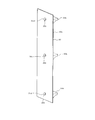
左内板部15Aと右内板部15Bとは、左右対称形に構成されている。左内板部15Aおよび右内板部15Bは、例えばABS樹脂などの合成樹脂製であって、平板状のシート部材Saで構成されている。なお、図5において、シート部材Saは、後述する固定具26、棚板支持具30、ガイドレール取付具33、34、仕切り壁支持具35、36を予め取り付けた形態で示されている。
上内板部15Cは、図6にも示すように、L状部17を一体に有している。L状部17は、折れ曲がり部として機能し、庫内すなわち断熱箱体2の内側へ膨出している。上内板部15Cは、例えばオレフィン樹脂のなどの合成樹脂製の一体成形品Iaで構成されている。
下内板部15Dは、図7にも示すように、排水受け部18を一体に有している。排水受け部18は、折れ曲がり部として機能する。下内板部15Dは、合成樹脂製の一体成形品Ibで構成されている。これら一体成形品Ia、Ibは、インジェクション成形や真空成形により形成されている。
奥内板部15Eは、図1および図2に示すように、合成樹脂製の平板状のシート部材Sbから構成されている。なお、シート部材Saおよびシート部材Sbは、特別形状の成形型を用いないで、押出し成形や圧延成形などで製造できる。また、市販品の平板状のシート部材を使用しても良い。
図4に示すように、外箱14と内箱15との間には、真空断熱パネル16が設けられている。真空断熱パネル16は、複数に分割された板状の単位パネルから構成されている。すなわち、真空断熱パネル16は、左単位パネル16Aと、右単位パネル16Bと、図10に示す上単位パネル16Cと、図示しない下単位パネルと、奥単位パネル16Eとから構成されている。各単位パネルは、基本的な構成は同じであるので、例えば左単位パネル16Aについて説明する。
左単位パネル16Aは、図8および図9に示すように、基材19を包体20に収容し、その内部を真空排気により減圧密封させて構成されている。基材19は、例えばグラスウールなどの無機繊維の積層材を圧縮硬化させて板状に成形されたものである。包体20は、気体を通し難くするガスバリア性能を得るために、例えばアルミ蒸着層やアルミ箔層などの金属層を含んで構成されている。各単位パネルは、一般的には真空断熱パネルとして呼ばれるものである。
左側断熱壁9は、図5に示すように、左外板部14Aと左内板部15Aとの間に左単位パネル16Aを配置し、これら三者を接着剤により接着して単位断熱壁として構成されている。
外箱14と内箱15とにおける前端部、つまり左側断熱壁9および右側断熱壁10の前端部は、図8に示すように、前端用連結部材21により連結されている。つまり、左側断熱壁9の前端部について見ると、左外板部14Aおよび左内板部15Aの前端部は、前端用連結部材21によって相互に連結されている。前端用連結部材21は、合成樹脂製であって断熱性能を有している。この場合、左側断熱壁9の前端部および右側断熱壁10の前端部は、左右対称形であるので、左側断熱壁9の前端部の構成について説明する。
左外板部14Aおよび左内板部15Aの前端部は、それぞれ左単位パネル16Aの前端部から前方に延び出ている。左外板部14Aは、前端部において左内板部15A側へ折れ曲がり、左単位パネル16Aの厚さ方向における中央部分まで延びている。この左外板部14A前端の折れ曲がった部分を、折曲部14Aaとする。この場合、折曲部14Aaは、断熱箱体2の内側つまり貯蔵室側には入り込んでいない。すなわち、折曲部14Aaは、左内板部15Aよりも右側へ延びていない。これにより、断熱箱体2の外部の熱は、外箱14この場合左外板部14Aを伝って貯蔵室へ流入することが抑制される。
左単位パネル16Aの前端部、左外板部14Aの前端部内面、および前端用連結部材21の内面で形成された内部空間部には、例えばソフトテープ22などで構成された断熱材が設けられている。なお、ソフトテープ22に代えて、発泡スチロールで構成しても良い。
右側断熱壁10は、左側断熱壁9と同様の構成であって左右対称形に構成されている。
上側断熱壁11は、図10に示すように、上外板部14Cと上内板部15Cとの間に上単位パネル16Cを有している。上単位パネル16Cは、上内板部15Cに接着されている。上単位パネル16Cと上外板部14Cとの間には、発泡ウレタン24が充填されている。上外板部14Cは、図2に示すように、上内板部15CのL状部17に対応して、L状部17aを有している。これにより、上側断熱壁11は、全体として後部が下側へ突出している。つまり、上側断熱壁11は、後部に凹状部11aを有している。凹状部11aの後方の空間は、機械室11bとして機能する。機械室11bには、冷凍サイクルを構成する図示しないコンプレッサや凝縮器などが設けられる。機械室11bは、図3に示すように、機械室カバー11cによって閉塞されている。
上側断熱壁11は、図10に示すように、上外板部14Cと上内板部15Cとの間に上単位パネル16Cを有している。上単位パネル16Cは、上内板部15Cに接着されている。上単位パネル16Cと上外板部14Cとの間には、発泡ウレタン24が充填されている。上外板部14Cは、図2に示すように、上内板部15CのL状部17に対応して、L状部17aを有している。これにより、上側断熱壁11は、全体として後部が下側へ突出している。つまり、上側断熱壁11は、後部に凹状部11aを有している。凹状部11aの後方の空間は、機械室11bとして機能する。機械室11bには、冷凍サイクルを構成する図示しないコンプレッサや凝縮器などが設けられる。機械室11bは、図3に示すように、機械室カバー11cによって閉塞されている。
図10に示すように、上単位パネル16Cと上外板部14Cとの間の寸法、つまり発泡ウレタン24が充填されている部分の厚み寸法は、上単位パネル16Cの厚みよりも小さく、かつ、冷凍サイクルの配管、例えばサクションパイプの外径よりも小さく設定されている。これにより、発泡ウレタン24の使用量は低減される。図10において、冷凍サイクルの配管を引き回す場合、該配管を、断熱箱体2の左上部のコーナー部において前後方向へ通すようにしても良い。この場合、コーナー部とは、上単位パネル16Cの左端面と、左単位パネル16Aの上端面と、上外板部14Cの左端縁部と、左外板部14Aの上端縁部とで囲まれた空間を示す。
図10に示すように、上外板部14Cの左端部は、上単位パネル16Cの上面から離間して左外板部14Aに連結されている。詳細は図示しないが、上外板部14Cの右端部も同様に、上単位パネル16Cの上面から離間して右外板部14Bに連結されている。上内板部15Cは、連結部15C1を有している。連結部15C1は、図6にも示すように、上内板部15Cの左右両側の縁部に設けられている。連結部15C1は、図10に示すように、上内板部15Cと左内板部15Aとを連結する。この場合、連結部15C1の先端部は、左内板部15Aに対し、図示しない連結具によって連結されている。
ここで、左側の連結部15C1について説明する。なお、右側の連結部は、左右対称形であることを除いて左側の連結部15C1と同様に構成されている。図10に示すように、連結部15C1は、リブ15C2を有している。リブ15C2は、連結部15C1の先端部の内側すなわち発泡ウレタン24側にあって、左内板部15Aとほぼ平行に上方へ突出している。リブ15C2と左内板部15Aとの間には、断熱材漏れ防止部材として例えばソフトテープ23が挿入されている。ソフトテープ23は、発泡ウレタン24の充填時における発泡ウレタン24の漏れを抑制している。
下側断熱壁12は、下外板部14Dと下内板部15Dとの間に図示しない下単位パネルを有している。下単位パネルは、下外板部14Dおよび下内板部15Dにそれぞれ接着されている。これにより、単位断熱壁が構成されている。なお、下側断熱壁12は、下内板部15Dと下単位パネルとを接着し、下単位パネルと下外板部14Dとの間に発泡ウレタンを充填して固化させることにより構成しても良い。この下側断熱壁12において、排水受け部18の最下部は、断熱箱体2外部に連通している。
なお、奥側断熱壁13も後外板部14Eと奥内板部15Eとの間に奥単位パネル16Eを配置し、これら三者を接着剤により接着して構成されている。この場合も、適宜発泡ウレタンを充填し固化した構成を追加しても良い。
また、上内板部15Cおよび下内板部15Dについて、オレフィン樹脂で構成された一体成形品Ia、Ibは、単位パネルとの接着面を粗い面となるように表面加工することで、単位パネルとの接着性を向上させている。また、左内板部15A、右内板部15B、奥内板部15Eについて、シート部材Sa、Sbは、ABS樹脂製であるため、単位パネルとの接着性が良い。
ここで、図9、図11~図14を参照して、左側断熱壁9と奥側断熱壁13との連結について説明する。左側断熱壁9と奥側断熱壁13とは、シート部材用連結板25および固定具26などで連結されている。この場合、シート部材用連結板25は、シート部材用連結部材として機能し、固定具26は第一突出部として機能する。以下、左側断熱壁9と奥側断熱壁13との連結部分の構成について説明する。なお、右側断熱壁10と奥側断熱壁13との連結部分の構成は、左右対称形であることを除いて左側断熱壁9と奥側断熱壁13との連結部分の構成と同様に構成されている。
まず、固定具26について説明する。固定具26は、左側断熱壁9および奥側断熱壁13にあって、それぞれ庫内側へ突出して設けられている。固定具26の構造および固定具26の取付部分の構造は、左側断熱壁9および奥側断熱壁13で共通しているため、以下、左側断熱壁9の固定具26について述べる。固定具26は、例えばABS樹脂などの合成樹脂製であって、上下方向へ長い矩形の直方体状に形成されている。固定具26は、鍔状部26aおよびねじ孔部26cを有している。鍔状部26aは、固定具26の直方体状の一端部側にあって、上下方向へ突出して設けられている。ねじ孔部26cは、固定具26の直方体状の他端面から一端部側へ向かって形成された雌ねじである。
左側断熱壁9を組み立てる際、まず、左単位パネル16Aに対して、固定具26を接着する。ここで、左内板部15Aすなわちシール部材Saは、予め形成されたやや縦長な矩形状の孔部15uを有している。固定具26は、左単位パネル16Aに接着された後、孔部15uに対して、左内板部15Aの裏側すなわち左単位パネル16A側から表側すなわち貯蔵室側へ向かって挿入される。このとき、左単位パネル16Aと左内板部15Aとの間には接着剤が設けられている。そのため、左単位パネル16Aと左内板部15Aとは接着される。このとき、鍔状部26aが左内板部15Aと左単位パネル16Aとの間に挟まれることによって、固定具26は固定される。このように、固定具26は、左側断熱壁9に取り付けられて内箱15内に突出している。そして、固定具26は、左側断熱壁9および奥側断熱壁13における隣接するそれぞれの端部において上下複数個所に設けられている。
図1および図2に示すように、シート部材用連結板25は、左内板部15Aと上下方向においてほぼ同じ長さに形成されている。図9に示すように、シート部材用連結板25は、水平方向の両端縁部おいて、L形に凹んだ凹み部25aを有している。凹み部25aは、それぞれ固定具26に対応している。凹み部25aには、ねじ挿通孔部25bが形成されている。ねじ挿通孔部25bには、ねじ27が通されている。ねじ27は、固定具26のねじ孔部26cにねじ込まれている。これにより、左内板部15Aと奥内板部15Eとがシート部材用連結板25によって連結されている。シート部材用連結板25は、冷蔵室57、野菜室58、小冷凍室59、製氷室60、冷凍室61の両側のコーナーに設けられている。
シート部材用連結板25の裏側の空間部、すなわち、シート部材用連結板25と左内板部15Aと奥内板部15Eとで囲まれた空間には、発泡スチロール28およびソフトテープ29が設けられている。この発泡スチロール28およびソフトテープ29は、断熱部材として機能する。
なお、冷凍サイクルの配管は、図9の発泡スチロール28部分において上下方向へ延びるように通しても良い。
左側断熱壁9および右側断熱壁10には、図1および図5に示すように、棚板支持具30が設けられている。以下、図16~図18も参照して、棚板支持具30の構成について説明する。なお、右側断熱壁10に設けられた棚板支持具30は、左側断熱壁9に設けられた棚板支持具30と同様に構成されている。
左側断熱壁9および右側断熱壁10には、図1および図5に示すように、棚板支持具30が設けられている。以下、図16~図18も参照して、棚板支持具30の構成について説明する。なお、右側断熱壁10に設けられた棚板支持具30は、左側断熱壁9に設けられた棚板支持具30と同様に構成されている。
棚板支持具30は、シート部材Saで構成された内板部15A、15Bとは別部品であって、例えばABS樹脂などの合成樹脂で構成されている。棚板支持具30は、本体部30a、棚板支持部30b、およびねじ孔部30cを一体に有している。本体部30aは、上下方向に長い矩形の板状に形成されている。棚板支持部30bは、本体部30aの一方の面に設けられ、庫内側へ突出している。この場合、棚板支持部30bは、第二突出部として機能する。棚板支持部30bは、本体部30aに対して上下方向へ三つ並んで設けられている。ねじ孔部30cは、本体部30aの棚板支持部30bに対応する位置に設けられている。各ねじ孔部30cは、それぞれ本体部30aにおいて棚板支持部30bと反対側の面から棚板支持部30b側へ向かって本体部30aを貫き、さらに棚板支持部30bを途中まで貫いて形成されている。ねじ孔部30cは、内側に雌ねじが形成されている。ねじ孔部30cは、締結部材係合部として機能する。ねじ孔部30cの開口周縁部には、円錐形に開口したいわゆる皿モミ形状の座ぐり30dが形成されている。
左内板部15Aは、図17に示すように、ねじ挿通孔部31を有している。ねじ挿通孔部31は、締結部材挿通孔部として機能する。ねじ挿通孔部31は、図1に示す冷蔵室57に相当する部分において、上下方向へ三つ並んで設けられている。なお、図17では、三つのねじ挿通孔部31のうち一つについて示している。棚板支持具30は、左側断熱壁9を組み立てる前に、左内板部15Aに取り付けられる。この場合、棚板支持具30のねじ孔部30cには、左内板部15Aのねじ挿通孔部31に通された皿ねじ32がねじ込まれる。これにより、棚板支持具30は、左内板部15A内面すなわち冷蔵室57側の面において、冷蔵室57側へ突出した形態で固定される。この場合、皿ねじ32は、締結部材として機能する。
この場合、左内板部15Aは、シート部材であるため若干の変形が可能である。そのため、皿ねじ32をねじ孔部30cにねじ込む過程で、皿ねじ32の皿状のねじ頭部32aは、座ぐり30dに当たるまで、左内板部15Aのねじ挿通孔部31周縁部を庫内側すなわち冷蔵室57側へ膨出するように皿状に変形させる。この結果、図18に示すように、ねじ挿通孔部31の周縁部31aは、左単位パネル16Aに対して離間する。また、皿ねじ32の端部であるねじ頭部32aは、左内板部15Aの裏面から左単位パネル16A側へ突出しない。
左側断熱壁9および右側断熱壁10には、図1、図2、および図5に示すように、ガイドレール取付具33、34が設けられている。ガイドレール取付具33は、野菜室58に対応し、ガイドレール取付具34は、冷凍室61に対応している。ガイドレール取付具33、34は、いずれも合成樹脂製であってシート部材とは別部品で構成されている。ガイドレール取付具33、34は、左右の内板部15A、15Bから庫内側へ突出する第二突出部として機能する。
ガイドレール取付具33、34は、棚板支持具30と同様に、左内板部15Aおよび右内板部15Bに取り付けられている。なお、ガイドレール取付具33、34には、図示しないガイドレールが設けられる。このガイドレールは、詳細は図示しないが、引き出し式扉5、8と一体化された容器を引き出し可能に支持する。
左側断熱壁9および右側断熱壁10には、図1、図2、および図5に示すように、仕切り壁支持具35、36が設けられている。仕切り壁支持具35は、第一仕切り壁55を支持し、仕切り壁支持具36は、第二仕切り壁56を支持する。仕切り壁支持具35、36は、いずれも合成樹脂製であってシート部材とは別部品で構成されている。仕切り壁支持具35、36は、固定具26と同様の構成によって、内板部15A、15Bに取り付けられている。この場合、仕切り壁支持具35、36は、左右の内板部15A、15Bから庫内側へ突出する第一突出部として機能する。
奥側断熱壁13における内箱15内面、つまりシート部材Sbで構成された奥内板部15Eには、適宜の箇所に、背面カバー取付具37が設けられている。背面カバー取付具37は、合成樹脂製であって、シート部材Sbで構成された奥内板部15Eとは別部品である。背面カバー取付具37は、奥内板部15Eから庫内側へ突出する突出部として機能する。背面カバー取付具37は、奥側断熱壁13の前方部分に配置されるダクトなどを隠すための背面カバーを取り付けるためのものである。背面カバー取付具37は、固定具26と同様の構成によって、奥内板部15Eに取り付けられている。この場合、背面カバー取付具37は、奥内板部15Eから庫内側へ突出する第一突出部として機能する。
各断熱壁9~13は、各内板部と各単位パネルとの間には発泡ウレタンを充填していない。
また、図2に示すように、冷凍室61の奥部には、冷凍サイクルの蒸発器64が配設されている。蒸発器64の下方には、排水受け部18が設けられている。排水受け部18は、蒸発器64に付着した霜を除霜した際に発生する除霜水を受け、その除霜水を奥側断熱壁13外部下部へ導出する。
また、図2に示すように、冷凍室61の奥部には、冷凍サイクルの蒸発器64が配設されている。蒸発器64の下方には、排水受け部18が設けられている。排水受け部18は、蒸発器64に付着した霜を除霜した際に発生する除霜水を受け、その除霜水を奥側断熱壁13外部下部へ導出する。
次に、図15を参照し、横梁部材52と、左側断熱壁9および右側断熱壁10との連結部分の構成について説明する。なお、図15では、横梁部材52と、左側断熱壁9との連結部分を示しているが、右側断熱壁10での連結部分の構成も左右対称形であることを除いて同様に構成されている。横梁部材52は、前面部を構成する前面仕切り板52aと、補強板52bと、裏仕切りカバー52cと、断熱材52dとを有している。左側断熱壁9の左外板部14Aは、前面部14A1を有している。前面部14A1は、先端部を折り返して形成された折り返し部14A2を有している。
前面仕切り板52aは、補強板52bと折り返し部14A2とで挟まれている。横梁部材52を組み立てる際、まず、前面仕切り板52aと補強板52bとを、ねじ63により一体化する。そして、前面仕切り板52aおよび補強板52bの左端部を、左外板部14Aの前面部14A1裏側に挿入する。その後、ねじ62を、左外板部14Aの折り返し部14A2および前面仕切り板52aの端部の穴に通し、補強板52bのねじ孔にねじ込む。これにより、前面仕切り板52aは、補強板52bと折り返し部14A2との間に挟まれて固定される。
前面仕切り板52aの後側には、断熱材52dを収容した裏仕切りカバー52cが取り付けられている。前面仕切り板52aにより、断熱箱体2における前面開口の左右縁部を連結することで、左側断熱壁9と右側断熱壁10とが固定される。これにより、断熱箱体2における前面開口が開いたり縮んだりすることを防止でき、貯蔵室を直方体に保つことができる。
なお、前面仕切り板52aの強度が十分である場合には、補強板52bを設けなくても良い。
また、裏仕切りカバー52cは、図示しないが、下方に突出する取付部を有し、この取付部が、前記固定具26と同様の固定具によりねじ止めされている。
また、裏仕切りカバー52cは、図示しないが、下方に突出する取付部を有し、この取付部が、前記固定具26と同様の固定具によりねじ止めされている。
上記第一実施形態によれば、内箱15の左内板部15Aおよび右内板部15Bは、平板状のシート部材Saで構成されている。また、奥内板部15Eは、平板状のシート部材Sbで構成されている。これによれば、左内板部15A、右内板部15B、および奥内板部15Eは、製造の際に成形型を必要とせず、したがって製作が極めて簡単となり、その結果、製作コストの低減にも寄与できる。
なお、内箱15における他の部分である上内板部15Cおよび下内板部15Dは、型による一体成形品とした。しかし、内箱15全体を大きな型によって一体成形する従来構成に比べて、製作が容易であり、また製作コストも低減できる。総じて冷蔵庫1のコストの低廉化に寄与できる。
この場合、左内板部15A、右内板部15B、上内板部15C、下内板部15D、奥内板部15Eの少なくとも一つをシート部材で構成すれば良い。
この場合、左内板部15A、右内板部15B、上内板部15C、下内板部15D、奥内板部15Eの少なくとも一つをシート部材で構成すれば良い。
また、この実施形態において、内箱15は、左内板部15A、右内板部15B、上内板部15C、下内板部15D、奥内板部15Eを組み合わせて構成されている。この場合、隣接する二つの内板部である左内板部15A、奥内板部15E、右内板部15Bは、それぞれ別々のシート部材で分割して構成されている。そして、この隣接する内板部間である左内板部15Aと奥内板部15Eとの間、および右内板部15Bと奥内板部15Eとの間には、それぞれ隣接する内板部を連結するシート部材用連結部材としてのシート部材用連結板25、25が設けられている。
これによれば、シート部材で構成された左内板部15Aと奥内板部15E、および右内板部15Bと奥内板部15Eを、別部品のシート部材用連結板25、25を用いることで簡単に連結することができ、組み立ての簡単化を図り得る。
また、第一実施形態において、断熱箱体2は、複数に分割された単位断熱壁、すなわち、左側断熱壁9、右側断熱壁10、上側断熱壁11、下側断熱壁12、奥側断熱壁13を連結して構成されている。従来構成において、断熱箱体は、分割されていない外箱と内箱との組み立てにより構成していたため、大型で組み立て作業も大がかりであった。しかし、本実施形態では、断熱箱体2は、真空断熱パネルを有する断熱壁9~13を組み立てることにより構成できるため、組み立てが簡単であり、組み立て作業が大がかりなものとならず、作業も容易となる。
また、第一実施形態によれば、内箱15においてシート部材で構成された部分の前端部と外箱14の前端部とを前端用連結部材21によって連結している。そのため、内箱15においてシート部材で構成された部分であっても、外箱14と別部品である前端用連結部材21により簡単に組み立てる、つまり接合することができる。
また、第一実施形態において、内箱15は、上側断熱壁11においてL状部17を有し、下側断熱壁12において排水受け部18を有している。L状部17は、上内板部15Cに一体に形成され、排水受け部18は、下内板部15Dに一体に形成されている。これによれば、L状部17や排水受け部18は、複雑な形状であっても、内板部15C、15Dに対して一体成形することにより容易に形成することができる。
また、第一実施形態において、内箱15は、シート部材Sa、Sbとは別部品で構成されて庫内側へ突出する第一突出部である固定具26を有している。固定具26は、左側断熱壁9が組み立てられる前の段階において、左単位パネル16Aに例えば直接接着される。そして、シート部材Saで構成された左右の内板部15A、15B、およびシート部材Sbで構成された奥内板部15Eには、孔部15uが形成されている。固定具26は、孔部15uに通されて設けられる。
これによれば、固定具26を孔部15uに挿入することで、内箱15すなわちシート部材Sa、Sbに対して固定具26の位置を決定することができる。なお、仕切り壁支持具35、36、および背面カバー取付具37も、固定具26と同様の取付構造としている。したがって、仕切り壁支持具35、36、および背面カバー取付具37も、固定具26と同様に位置が決定される。
なお、固定具26は、左側断熱壁9が組み立てられる前の段階において、孔部15uに対し、シート部材Sa、Sbの裏側から挿入し接着するようにしても良い。これによれば、固定具26とシート部材とを一体の状態で取り扱うことができる。そのため、単位断熱壁を組み立てる際に、単位パネルと、固定具26およびシート部材Sa、Sbの一体品とを接着でき、組み立て作業性が良くなる。
図13に示すように、単位パネル16Aにおける固定具26取付面を窪ませても良い。これによれば、シート部材Saを湾曲させることなく、固定具26を取り付けることができる。
また、仮に単位パネル16Aが膨らんだ場合でも、内板部15Aがシート部材Saから構成されているから、内板部15Aが割れることなく若干変形する程度で済む。
また、固定具26、棚板支持具30、ガイドレール取付具33、34、仕切り壁支持具35、36は、異なる機種の冷蔵庫の断熱箱体にも、共通して使用することができる。
また、固定具26、棚板支持具30、ガイドレール取付具33、34、仕切り壁支持具35、36は、異なる機種の冷蔵庫の断熱箱体にも、共通して使用することができる。
また、第一実施形態によれば、固定具26は、左単位パネル16A、右単位パネル16Bおよび奥単位パネル16Eに直接接着される。このため、各単位パネル16A、16B、16Eは、それぞれ固定具26を対応する各内板部15A、15B、15Eの孔部15uに挿入することで、各内板部15A、15B、15Eに対して容易に位置を決定することができる。この場合、固定具26は、接着性の良いABS樹脂製で構成されているため、固定具26と各単位パネル16A、16B、16Eとの接着強度の向上が図られる。
また、仕切り壁支持具35、36、および背面カバー取付具37も、固定具26と同様の取付構造としている。したがって、これら仕切り壁支持具35、36、および背面カバー取付具37も、各内板部と各単位パネルとの位置合わせに寄与できる。
なお、固定具26は、別部材を介して各単位パネル16A、16B、16Eに接着しても良い。
なお、固定具26は、別部材を介して各単位パネル16A、16B、16Eに接着しても良い。
また、上記第一実施形態において、固定具26は、孔部15uよりも大きい鍔状部26aを有している。そして、鍔状部26aは、シート部材Sa、Sbと、これらに対応する単位パネルとの間に挟まれている。これによれば、固定具26は、鍔状部26aによって孔部15uから抜けることを抑制できる。また、鍔状部26aを対応する内板部に接着することができ、当該対応する内板部の強度向上にも寄与できる。また、鍔状部26aは薄肉に構成されている。そのため、固定具26は、鍔状部26aをたわませることで、庫内側から孔部15uを通し、当該内板部と単位パネルとの間に挿入することもできる。
また、第一実施形態において、内箱15は、第二突出部として棚板支持部30bを有している。棚板支持部30bを有する棚板支持具30は、左右の内板部15A、15Bを構成するシート部材Saとは別部品で構成されて、庫内側へ突出している。シート部材Saには、ねじ挿通孔部31が形成されている。棚板支持具30は、ねじ挿通孔部31に対してシート部材Saの裏側つまり庫内と反対側から、庫内側へ向かって通された皿ねじ32によって、シート部材Saの表面側すなわち庫内側の面に固定されている。
これによれば、棚板支持具30は、シート部材Saに対して締結部材である皿ねじ32によって取り付けることができる。なお、この場合、締結部材としてリベットを用いても良い。リベットは、例えばシート部材Saおよび棚板支持具30を貫通し、その両端部がかしめられることで、棚板支持具30をシート部材Saに固定する。
また、第一実施形態において、ねじ挿通孔部31の周縁部31aは、真空断熱パネルである左右の単位パネル16A、16Bから離間している。すなわち、皿ねじ32のねじ頭部32aは、ねじ挿通孔部31の周縁部31aから左右の単位パネル16A、16B側へそれぞれ突出していない。
これによれば、ねじ頭部32aは、各内板部15A、15Bの裏面すなわち単位パネル16A、16B側へ突出していない。そのため、ねじ頭部32aが各単位パネル16A、16Bに接触することが回避される。したがって、ねじ頭部32aの接触により各単位パネル16A、16Bの包体20が損傷することを回避できる。また、左単位パネル16Aと左内板部15Aとの接着、および右単位パネル16Bと右内板部15Bとの接着は、ねじ頭部32aによって阻害されることがない。
さらに、棚板支持具30は、ねじ孔部30cの開口周縁部を、皿状の座ぐり30dとしている。これにより、皿ねじ32をねじ孔部30cにねじ込む際、シート部材Saにおけるねじ挿通孔部31の周縁部31aは、座ぐり30d側へ変形し、自ずと左右の単位パネル16A、16Bから離間する。これによれば、シート部材Saに、ねじ頭部32aを納めるための窪みをわざわざ形成する必要がない。
なお、ガイドレール取付具33、34も、棚板支持具30と同様の取付構造としている。したがって、ガイドレール取付具33、34部分についても、棚板支持具30と同様の効果を奏する。また、右側断熱壁10に設けられた図示しない棚板支持具30、ガイドレール取付具33、34部分についても、棚板支持具30と同様の効果を奏する。
(第二実施形態)
図19~図27は、第二実施形態を示している。第二実施形態では、左側断熱壁9‐2および右側断熱壁10‐2の構成が第一実施形態と異なる。以下、異なる点について、左側断熱壁9‐2を例に説明する。なお、右側断熱壁10‐2は、左側断熱壁9‐2と左右対称であることを除いて同様に構成されている。
図19~図27は、第二実施形態を示している。第二実施形態では、左側断熱壁9‐2および右側断熱壁10‐2の構成が第一実施形態と異なる。以下、異なる点について、左側断熱壁9‐2を例に説明する。なお、右側断熱壁10‐2は、左側断熱壁9‐2と左右対称であることを除いて同様に構成されている。
左側断熱壁9‐2において、内箱15の一部である左内板部15A‐2は、第三突出部として、棚板支持部40a、40b、40c、ガイドレール取付部41a、41b、および仕切り壁支持部42a、42bを有している。左内板部15A‐2は、これら棚板支持部40a、40b、40c、ガイドレール取付部41a、41b、および仕切り壁支持部42a、42bを一体に形成した一体成形品Icで構成されている。一体成形品Icは、型による成形、例えばインジェクション成形や真空成形により形成される。棚板支持部40a、40b、40c、ガイドレール取付部41a、41b、および仕切り壁支持部42a、42bは、それぞれ庫内側へ突出している。
図21に示すように、左内板部15A‐2は、奥側端部にシート部材用連結部25‐2を有している。シート部材用連結部25‐2は、左内板部15A‐2と一体に形成されている。シート部材用連結部25‐2は、左内板部15A‐2と奥内板部15Eとを連結するためのシート部材用連結部材として機能する。シート部材用連結部25‐2は、図22に示すように、奥内板部15Eに取り付けられた固定具26によって、奥側断熱壁13に連結される。
図21に示すように、棚板支持部40a、40b、40cと、ガイドレール取付部41a、41bとは、前後方向の長さが異なる。この場合、ガイドレール取付部41a、41bは、棚板支持部40a、40b、40cに比べて前後方向に長い。一方、棚板支持部40a、40b、40c、およびガイドレール取付部41a、41bは、上下方向の断面形状が同様に構成されている。このように、ガイドレール取付部41a、41bは、具体的な形状を除いて、棚板支持部40a、40b、40cとほぼ同様に構成されている。したがって、以下では、棚板支持部40aについて説明し、棚板支持部40b、40c、およびガイドレール取付部41a、41bの説明については省略する。
棚板支持部40aは、図22~図25に示すように、一体成形品Icとして左内板部15A‐2と一体に形成されている。棚板支持部40aは、左内板部15A‐2の庫内側の面から庫内方向へ突出している。棚板支持部40aは、図23に示すように、庫内と反対側の面の一部にねじボス部43が形成されている。ねじボス部43には、ねじ孔部43aが形成されている。
棚板支持部40aの庫内と反対側の内面部分には、補強部材として例えば金属板製の補強板44が取り付けられる。補強板44は、棚板支持部40aの庫内と反対側の内面に沿う形状に形成されている。補強板44は、ボス部嵌合部44aを有している。ボス部嵌合部44aには、ねじ挿通孔部44bが形成されている。補強板44は、ボス部嵌合部44aを棚板支持部40aの内面部分に当てた形態で、ねじ挿通孔部44bにねじ45を通す。そして、そのねじ45をねじ孔部43aにねじ込むことによって、補強板44は、棚板支持部40aすなわち左内板部15A‐2に取り付けられる。これにより、補強板44は、棚板支持部40aを補強している。
仕切り壁支持部42a、42bは、第一実施形態の仕切り壁支持具35、36に相当する。図26および図27に示すように、仕切り壁支持部42a、42bの内面には、補強部材として例えば金属板製の補強板46が設けられている。補強板46は、ねじ47によって取り付けられている。このように、仕切り壁支持部42a、42bは、補強板46によって補強されている。
なお、補強板44、46のねじ止めは必要に応じて行えば良い。例えば、補強板44、46は、ねじに換えて接着する構成でも良い。この場合、補強板44、46は、左単位パネル16Aと左内板部15A‐2との間にあって、突出部である棚板支持部40a、40b、40c、ガイドレール取付部41a、41b、仕切り壁支持部42a、42bを補強する構成であれば良い。
第二実施形態によれば、第三突出部である棚板支持部40a、40b、40c、ガイドレール取付部41a、41b、および仕切り壁支持部42a、42bは、一体成形品Icとして一体に構成されている。そのため、これら第三突出部を別部品で構成する必要がない。そして、第三突出部である棚板支持部40a、40b、40c、ガイドレール取付部41a、41b、および仕切り壁支持部42a、42bは、補強板44、46によって補強されている。そのため、本実施形態による第三突出部は、突出部を別部品とする構成に比べて強度の低い材料を用いた場合であっても、十分な強度を得ることができる。したがって、本実施形態によれば、一体成形品Icの材料として、ABS樹脂に比べて強度は低いが低コストである例えばポリプロピレン材料などのオレフィン樹脂を用いることができる。
(第三実施形態)
図28および図29は第三実施形態を示している。第三実施形態においては、左側断熱壁9‐3および右側断熱壁10‐3の構成が第一実施形態および第二実施形態と異なる。以下、異なる点について説明する。この場合、左側断熱壁9‐3および右側断熱壁10‐3は左右対称形であることを除いて同様の構成である。したがって、左側断熱壁9‐3について説明する。
図28および図29は第三実施形態を示している。第三実施形態においては、左側断熱壁9‐3および右側断熱壁10‐3の構成が第一実施形態および第二実施形態と異なる。以下、異なる点について説明する。この場合、左側断熱壁9‐3および右側断熱壁10‐3は左右対称形であることを除いて同様の構成である。したがって、左側断熱壁9‐3について説明する。
左側断熱壁9‐3は、図29に示すように、単位パネル16Aおよび左内板部15Aを有している。左内板部15Aは、上側板部15Aaと下側板部15Abとに分割されている。これら上側板部15Aaと下側板部15Abとは、上下に隣接している。上側板部15Aaは、例えばインジェクション成形または真空成形などにより一体成形品Idとして構成されている。上側板部15Aaは、第二実施形態と同様に第三突出部として棚板支持部40a、40b、40c、およびシート部材用連結部25‐2を一体に有している。シート部材用連結部25‐2は、冷蔵室57側に位置している。また、図28に示すように、下側板部15Ab側と奥内板部15Eとはシート部材用連結板25‐3によって連結されている。シート部材用連結板25‐3は、上側板部15Aaおよび下側板部15Abとは別部品として構成されている。そして、シート部材用連結板25‐3は、野菜室58、小冷凍室59、製氷室60および冷凍室61側に位置している。
下側板部15Abは、平板状のシート部材Scから構成されている。下側板部15Abは、第一実施形態と同様に、シート部材Scとは別部品の第一突出部として固定具26および仕切り壁支持具35、36を有し、第二突出部としてガイドレール取付具33、34を有している。突出部は、それぞれ第一実施形態と同様に取り付けられている。このように、上側板部15Aaは、冷蔵室57に位置して冷蔵室57の内面を構成している。
この第三実施形態によれば、回転扉3、4を有する冷蔵室57の内面は、一体成形品Idである上側板部15Aaによって構成されている。そのため、冷蔵室57内面の見栄えが良い。すなわち、冷蔵室57の内面は、回転扉3、4を開放した際に、使用者に視認され易い。本実施形態によれば、冷蔵室57の内面は、棚板支持部40a、40b、40cを一体に有した一体成形品Idによって構成されている。そのため、棚板支持部40a、40b、40cは、上側板部15Aaから滑らかに突出する形態となり、したがって、見栄えが良い。また、この構成によれば、棚板支持部40a、40b、40cと、上側板部15Aaとの隙間が形成されないため、隙間に異物などが入り込むこともない。そのため、上側板部15Aaの清掃性が向上し、よって衛生面での印象も良くなる。
(第四実施形態)
図30および図31は第四実施形態を示している。第四実施形態では、棚板支持具30が、ひれ部30eを有している点で第一実施形態と異なる。この場合、ひれ部30eは、覆い部として機能する。ひれ部30eは、棚板支持具30における本体部30aの周縁部にあって、本体部30aと一体に設けられている。図31に示すように、ひれ部30eは、内箱15内面側である左内板部15A側へ傾斜し、弾性変形可能に構成されている。
図30および図31は第四実施形態を示している。第四実施形態では、棚板支持具30が、ひれ部30eを有している点で第一実施形態と異なる。この場合、ひれ部30eは、覆い部として機能する。ひれ部30eは、棚板支持具30における本体部30aの周縁部にあって、本体部30aと一体に設けられている。図31に示すように、ひれ部30eは、内箱15内面側である左内板部15A側へ傾斜し、弾性変形可能に構成されている。
ひれ部30eは、棚板支持具30の取付状態において、内箱15内面のうち左内板部15Aに密接する。このひれ部30eにより、内箱15内面と棚板支持具30との間の隙間が隠される。すなわち、皿ねじ32を棚板支持具30のねじ孔部30cにねじ込む際、左内板部15Aのねじ挿通孔部31の周縁部31aが変形して、ねじ挿通孔部31部分にシワが発生することがある。そして、このシワによって、左内板部15Aと棚板支持具30との間に隙間が発生することがある。この第四実施形態によれば、この隙間は、ひれ部30eにより隠すことができる。
(第五実施形態)
図32~図34は第五実施形態を示している。第五実施形態では、次の点が第一実施形態と異なる。すなわち、第一実施形態では、内箱15の一部を構成する左外板部14Aと下外板部14Dと右外板部14Bとは、分割されていた。これに対し、本実施形態では、左外板部14Aと下外板部14Dと右外板部14Bとは、連続した外板部14Zによって構成されている。なお、符号16Dは、下外板部14Dと下内板部15Dとの間に設けられた単位パネルを示している。
図32~図34は第五実施形態を示している。第五実施形態では、次の点が第一実施形態と異なる。すなわち、第一実施形態では、内箱15の一部を構成する左外板部14Aと下外板部14Dと右外板部14Bとは、分割されていた。これに対し、本実施形態では、左外板部14Aと下外板部14Dと右外板部14Bとは、連続した外板部14Zによって構成されている。なお、符号16Dは、下外板部14Dと下内板部15Dとの間に設けられた単位パネルを示している。
この第五実施形態で示すように、外箱14は、各板部の全部が分割されていなくても良い。
また、図30および図31に示す第四実施形態では、棚板支持具30にひれ部30eを設けて、内箱15内面と棚板支持具30との間の隙間を当該ひれ部30eで隠すようにしたが、棚板支持具30自体を透明とすることで上記隙間を目立たなくするようにしても良い。
また、図30および図31に示す第四実施形態では、棚板支持具30にひれ部30eを設けて、内箱15内面と棚板支持具30との間の隙間を当該ひれ部30eで隠すようにしたが、棚板支持具30自体を透明とすることで上記隙間を目立たなくするようにしても良い。
なお、単位断熱壁としての各断熱壁9~13の内板部は、全てシート部材で構成されていても良いし、一つの内板部がシート部材で構成されていても良い。また、単位断熱壁は少なくとも2つであれば良い。例えば左側断熱壁9が単独であり、他の断熱壁10~13を一体とするように構成してもよい。つまり、断熱壁10~13は、外板部を連続して一体としたり、内板部を連続して一体としたり、単位パネルを連続して一体とするように構成しても良い。
また、単位断熱壁は、内板部と外板部との間に単位パネルを設け、内板部と単位パネルの一面とを接着し、単位パネルの他面と外板部とを接着する構成としても良い。また、単位断熱壁は、内板部と単位パネルの一面とを接着し、単位パネルの他面と外板部との間に発泡ウレタンなどの断熱材を介在させた構成でも良い。
また、外箱および真空断熱パネルは分割せずに内箱のみを複数の内板部に分割し連結した形態としても良い。
また、外箱および真空断熱パネルは分割せずに内箱のみを複数の内板部に分割し連結した形態としても良い。
以上のように本実施形態の冷蔵庫は、外箱と、内箱と、これら外箱および内箱の間に配置される真空断熱パネルとから構成された断熱箱体を備えた冷蔵庫であって、前記内箱の少なくとも一部を平板状のシート部材で構成した。これによれば、大きな型を必要とせず、製作が容易でコスト安となる。
本発明のいくつかの実施形態を説明したが、これらの実施形態は、例として提示したものであり、発明の範囲を限定することは意図していない。これら新規な実施形態は、その他の様々な形態で実施されることが可能であり、発明の要旨を逸脱しない範囲で、種々の省略、置き換え、変更を行うことができる。これら実施形態やその変形は、発明の範囲や要旨に含まれるとともに、特許請求の範囲に記載された発明とその均等の範囲に含まれる。
Claims (13)
- 外箱と、前記外箱の内側に設けられた内箱と、前記外箱および前記内箱の間に設けられた真空断熱パネルと、を有する断熱箱体を備え、
前記内箱の少なくとも一部を平板状のシート部材で構成した冷蔵庫。 - 前記内箱は、複数の内板部を有し、
前記複数の内板部において、隣接する少なくとも二つの内板部は別々の前記シート部材で分割して構成され、
この隣接する二つの前記内板部の間には、当該二つの内板部を連結するシート部材用連結部材が設けられている請求項1記載の冷蔵庫。 - 前記断熱箱体は、複数に分割された単位断熱壁を連結して構成され、
前記単位断熱壁は、前記外箱を複数に分割した外板部と前記内箱を複数に分割した内板部との間に、前記真空断熱パネルを複数に分割した単位パネルを有し、
前記複数の内板部のうち少なくとも一つは前記シート部材で構成されている請求項1または2記載の冷蔵庫。 - 前記内箱において前記シート部材で構成された部分の前端部と、前記外箱の前端部とは、前端用連結部材によって連結されている請求項1から3いずれか一項記載の冷蔵庫。
- 前記内箱は折れ曲がり部を有し、
前記内箱において前記折れ曲がり部を有する部分は、前記シート部材と異なる部材であって前記折れ曲がり部と一体に形成された一体成型品である請求項1から4いずれか一項記載の冷蔵庫。 - 前記内箱は、庫内側へ突出する第一突出部を有し、
前記第一突出部は、前記シート部材とは別部品で構成され、前記シート部材に形成された孔部に通されている請求項1から5いずれか一項記載の冷蔵庫。 - 前記第一突出部は、前記真空断熱パネルに固定されている請求項6に記載の冷蔵庫。
- 前記第一突出部は、前記孔部よりも大きい鍔状部を有し、
該鍔状部は、前記シート部材と前記真空断熱パネルとの間に挟まれている請求項6または7記載の冷蔵庫。 - 前記シート部材に形成された締結部材挿通孔部に対して庫内と反対側から通された締結部材をさらに備え、
前記内箱は、庫内側へ突出する第二突出部を有し、
前記第二突出部は、前記シート部材とは別部品で構成され、前記締結部材によって前記シート部材の庫内側の面に固定されている請求項1から8いずれか一項記載の冷蔵庫。 - 前記締結部材挿通孔部の周縁部は、前記真空断熱パネルから離間し、前記締結部材の端部は、前記締結部材挿通孔部の周縁部から前記真空断熱パネル側へ突出していない請求項9記載の冷蔵庫。
- 前記第二突出部は、該第二突出部と前記内板部との隙間を覆う覆い部を有している請求項9または10記載の冷蔵庫。
- 前記第二突出部は透明である請求項9または10に記載の冷蔵庫。
- 前記内箱は、庫内側へ突出する第三突出部を有し、
前記内箱において前記第三突出部を有する部分は、前記シート部材と異なる部材であって前記第三突出部と一体に形成された一体成形品で構成され、
前記第三突出部の内部には、該第三突出部を補強する補強部材が設けられている請求項1から12いずれか一項記載の冷蔵庫。
Priority Applications (2)
| Application Number | Priority Date | Filing Date | Title |
|---|---|---|---|
| EP12800424.9A EP2719981B1 (en) | 2011-06-13 | 2012-05-11 | Refrigerator |
| CN201280039506.2A CN103733008A (zh) | 2011-06-13 | 2012-05-11 | 电冰箱 |
Applications Claiming Priority (2)
| Application Number | Priority Date | Filing Date | Title |
|---|---|---|---|
| JP2011131136A JP5788232B2 (ja) | 2011-06-13 | 2011-06-13 | 冷蔵庫 |
| JP2011-131136 | 2011-06-13 |
Publications (1)
| Publication Number | Publication Date |
|---|---|
| WO2012172897A1 true WO2012172897A1 (ja) | 2012-12-20 |
Family
ID=47356892
Family Applications (1)
| Application Number | Title | Priority Date | Filing Date |
|---|---|---|---|
| PCT/JP2012/062167 WO2012172897A1 (ja) | 2011-06-13 | 2012-05-11 | 冷蔵庫 |
Country Status (5)
| Country | Link |
|---|---|
| EP (1) | EP2719981B1 (ja) |
| JP (1) | JP5788232B2 (ja) |
| CN (2) | CN108278847B (ja) |
| TW (1) | TWI544194B (ja) |
| WO (1) | WO2012172897A1 (ja) |
Cited By (7)
| Publication number | Priority date | Publication date | Assignee | Title |
|---|---|---|---|---|
| JP2014142170A (ja) * | 2012-12-26 | 2014-08-07 | Toshiba Corp | 冷蔵庫の断熱箱体の製造方法 |
| EP2818812A3 (en) * | 2013-06-25 | 2015-04-01 | Kabushiki Kaisha Toshiba | Refrigerator |
| CN104884884A (zh) * | 2012-12-25 | 2015-09-02 | 株式会社东芝 | 冰箱、冰箱的隔热箱体以及冰箱隔热箱体的制造方法 |
| JP2015161438A (ja) * | 2014-02-27 | 2015-09-07 | シャープ株式会社 | 冷蔵庫 |
| EP2940412A4 (en) * | 2012-12-25 | 2016-09-28 | Toshiba Kk | METHOD FOR PRODUCING A HEAT-INSULATING CONTAINER FOR A REFRIGERATOR AND REFRIGERATOR |
| AU2016216581B2 (en) * | 2013-06-07 | 2017-04-20 | Mitsubishi Electric Corporation | Heat insulating box body and refrigerator |
| EP3031899B1 (en) * | 2013-10-11 | 2018-09-19 | PHC Holdings Corporation | Culture apparatus |
Families Citing this family (10)
| Publication number | Priority date | Publication date | Assignee | Title |
|---|---|---|---|---|
| JP5812833B2 (ja) * | 2011-12-06 | 2015-11-17 | 株式会社東芝 | 冷蔵庫 |
| JP6089803B2 (ja) * | 2013-03-07 | 2017-03-08 | 三菱電機株式会社 | 貯湯式給湯機 |
| AU2014276244B2 (en) * | 2013-06-07 | 2016-05-19 | Mitsubishi Electric Corporation | Heat insulating box body, refrigerator, and device including heat insulating box body |
| CN103683065A (zh) * | 2013-12-04 | 2014-03-26 | 蒋计 | 一种箱式变电站 |
| EP3173719B1 (de) * | 2015-11-30 | 2020-05-27 | Liebherr-Hausgeräte Ochsenhausen GmbH | Kühl- und/oder gefriergerät |
| KR20210006717A (ko) * | 2019-07-09 | 2021-01-19 | 엘지전자 주식회사 | 진공단열모듈, 및 냉장고 |
| KR20210015080A (ko) * | 2019-07-31 | 2021-02-10 | 엘지전자 주식회사 | 진공단열모듈, 냉장고, 냉장고의 제조방법 |
| KR20220022976A (ko) * | 2020-08-20 | 2022-03-02 | 엘지전자 주식회사 | 냉장고 |
| DE102022200028A1 (de) | 2022-01-04 | 2023-07-06 | BSH Hausgeräte GmbH | Haushaltskältegerät mit einem konfigurierbaren Gehäuse, sowie Verfahren zur Montage eines Haushaltskältegeräts |
| DE102022200029A1 (de) | 2022-01-04 | 2023-07-06 | BSH Hausgeräte GmbH | Haushaltskältegerät mit einem konfigurierbaren Montagemodul, sowie Verfahren zur Montage eines Haushaltskältegeräts |
Citations (12)
| Publication number | Priority date | Publication date | Assignee | Title |
|---|---|---|---|---|
| JPS5661576A (en) * | 1979-10-24 | 1981-05-27 | Mitsubishi Electric Corp | Box of refrigerating chamber |
| JPS56161485U (ja) * | 1980-04-30 | 1981-12-01 | ||
| JPS58177783U (ja) * | 1982-04-30 | 1983-11-28 | 日本トレ−ルモ−ビル株式会社 | 冷凍コンテナにおける内部隅部構造 |
| JPS61186089U (ja) * | 1985-05-13 | 1986-11-20 | ||
| JPS63210589A (ja) * | 1987-02-25 | 1988-09-01 | 株式会社東芝 | 断熱箱体 |
| JPH02136683A (ja) * | 1988-11-17 | 1990-05-25 | Sanyo Electric Co Ltd | 断熱箱体 |
| JPH04260780A (ja) | 1991-02-15 | 1992-09-16 | Sharp Corp | 真空断熱箱体の製造方法 |
| JPH0635887U (ja) * | 1992-10-15 | 1994-05-13 | ホシザキ電機株式会社 | 断熱箱体の角部接続構造 |
| JPH06147744A (ja) | 1992-11-09 | 1994-05-27 | Hitachi Ltd | 冷凍冷蔵庫 |
| JPH07269779A (ja) * | 1994-03-28 | 1995-10-20 | Toshiba Corp | 断熱筐体及び真空断熱パネルの製造方法 |
| JPH10205994A (ja) * | 1997-01-14 | 1998-08-04 | Sanyo Electric Co Ltd | 冷却貯蔵庫の断熱箱体 |
| JP2009174842A (ja) * | 2007-12-27 | 2009-08-06 | Panasonic Corp | 冷蔵庫 |
Family Cites Families (14)
| Publication number | Priority date | Publication date | Assignee | Title |
|---|---|---|---|---|
| US2768046A (en) * | 1952-07-09 | 1956-10-23 | Gen Electric | Insulating structures |
| US5857307A (en) * | 1994-06-29 | 1999-01-12 | Sanyo Electric Co., Ltd. | Heat insulating structure and production process thereof |
| JPH0882475A (ja) * | 1994-09-13 | 1996-03-26 | Toshiba Corp | 断熱箱体 |
| IT236949Y1 (it) * | 1995-06-08 | 2000-08-31 | Devi Spa | Vano contenitore perfezionato in particolare per frigoriferi esimili elettrodomestici |
| US5875599A (en) * | 1995-09-25 | 1999-03-02 | Owens-Corning Fiberglas Technology Inc. | Modular insulation panels and insulated structures |
| US6109712A (en) * | 1998-07-16 | 2000-08-29 | Maytag Corporation | Integrated vacuum panel insulation for thermal cabinet structures |
| CN2459594Y (zh) * | 2000-09-01 | 2001-11-14 | 祁治理 | 电冰箱节能幕帘 |
| JP2003056968A (ja) * | 2001-08-08 | 2003-02-26 | Toshiba Corp | 冷蔵庫 |
| JP2003302153A (ja) * | 2002-04-09 | 2003-10-24 | Yodogawa Steel Works Ltd | 組立式の冷蔵庫 |
| CN101086317A (zh) * | 2006-06-06 | 2007-12-12 | 泰州乐金电子冷机有限公司 | 电冰箱用真空隔热材料及其隔热结构 |
| US7621148B1 (en) * | 2007-08-07 | 2009-11-24 | Dain John F | Ultra-low temperature bio-sample storage system |
| CN102037303A (zh) * | 2008-05-23 | 2011-04-27 | 伊莱克斯公司 | 制冷装置 |
| JP5312056B2 (ja) * | 2009-01-14 | 2013-10-09 | 株式会社クボタ | 空気調和機 |
| JP5797467B2 (ja) * | 2011-06-10 | 2015-10-21 | 株式会社東芝 | 冷蔵庫 |
-
2011
- 2011-06-13 JP JP2011131136A patent/JP5788232B2/ja active Active
-
2012
- 2012-05-11 CN CN201810182284.9A patent/CN108278847B/zh active Active
- 2012-05-11 CN CN201280039506.2A patent/CN103733008A/zh active Pending
- 2012-05-11 EP EP12800424.9A patent/EP2719981B1/en active Active
- 2012-05-11 WO PCT/JP2012/062167 patent/WO2012172897A1/ja active Application Filing
- 2012-05-29 TW TW101119120A patent/TWI544194B/zh not_active IP Right Cessation
Patent Citations (12)
| Publication number | Priority date | Publication date | Assignee | Title |
|---|---|---|---|---|
| JPS5661576A (en) * | 1979-10-24 | 1981-05-27 | Mitsubishi Electric Corp | Box of refrigerating chamber |
| JPS56161485U (ja) * | 1980-04-30 | 1981-12-01 | ||
| JPS58177783U (ja) * | 1982-04-30 | 1983-11-28 | 日本トレ−ルモ−ビル株式会社 | 冷凍コンテナにおける内部隅部構造 |
| JPS61186089U (ja) * | 1985-05-13 | 1986-11-20 | ||
| JPS63210589A (ja) * | 1987-02-25 | 1988-09-01 | 株式会社東芝 | 断熱箱体 |
| JPH02136683A (ja) * | 1988-11-17 | 1990-05-25 | Sanyo Electric Co Ltd | 断熱箱体 |
| JPH04260780A (ja) | 1991-02-15 | 1992-09-16 | Sharp Corp | 真空断熱箱体の製造方法 |
| JPH0635887U (ja) * | 1992-10-15 | 1994-05-13 | ホシザキ電機株式会社 | 断熱箱体の角部接続構造 |
| JPH06147744A (ja) | 1992-11-09 | 1994-05-27 | Hitachi Ltd | 冷凍冷蔵庫 |
| JPH07269779A (ja) * | 1994-03-28 | 1995-10-20 | Toshiba Corp | 断熱筐体及び真空断熱パネルの製造方法 |
| JPH10205994A (ja) * | 1997-01-14 | 1998-08-04 | Sanyo Electric Co Ltd | 冷却貯蔵庫の断熱箱体 |
| JP2009174842A (ja) * | 2007-12-27 | 2009-08-06 | Panasonic Corp | 冷蔵庫 |
Non-Patent Citations (1)
| Title |
|---|
| See also references of EP2719981A4 * |
Cited By (11)
| Publication number | Priority date | Publication date | Assignee | Title |
|---|---|---|---|---|
| CN104884884A (zh) * | 2012-12-25 | 2015-09-02 | 株式会社东芝 | 冰箱、冰箱的隔热箱体以及冰箱隔热箱体的制造方法 |
| EP2940412A4 (en) * | 2012-12-25 | 2016-09-28 | Toshiba Kk | METHOD FOR PRODUCING A HEAT-INSULATING CONTAINER FOR A REFRIGERATOR AND REFRIGERATOR |
| EP2940413A4 (en) * | 2012-12-25 | 2016-12-21 | Toshiba Lifestyle Products & Services Corp | REFRIGERATOR, THERMAL INSULATING HOUSING FOR REFRIGERATOR, AND METHOD FOR MANUFACTURING THERMAL INSULATING HOUSING FOR REFRIGERATOR |
| JP2014142170A (ja) * | 2012-12-26 | 2014-08-07 | Toshiba Corp | 冷蔵庫の断熱箱体の製造方法 |
| JP2018173269A (ja) * | 2012-12-26 | 2018-11-08 | 東芝ライフスタイル株式会社 | 冷蔵庫の断熱箱体の製造方法 |
| AU2016216581B2 (en) * | 2013-06-07 | 2017-04-20 | Mitsubishi Electric Corporation | Heat insulating box body and refrigerator |
| CN106016931B (zh) * | 2013-06-07 | 2019-04-19 | 三菱电机株式会社 | 冰箱 |
| EP2818812A3 (en) * | 2013-06-25 | 2015-04-01 | Kabushiki Kaisha Toshiba | Refrigerator |
| EP3031899B1 (en) * | 2013-10-11 | 2018-09-19 | PHC Holdings Corporation | Culture apparatus |
| US10150940B2 (en) | 2013-10-11 | 2018-12-11 | Phc Holdings Corporation | Culture apparatus |
| JP2015161438A (ja) * | 2014-02-27 | 2015-09-07 | シャープ株式会社 | 冷蔵庫 |
Also Published As
| Publication number | Publication date |
|---|---|
| EP2719981A4 (en) | 2015-05-27 |
| TW201312069A (zh) | 2013-03-16 |
| TWI544194B (zh) | 2016-08-01 |
| CN108278847A (zh) | 2018-07-13 |
| JP2013002654A (ja) | 2013-01-07 |
| CN108278847B (zh) | 2020-12-25 |
| CN103733008A (zh) | 2014-04-16 |
| EP2719981B1 (en) | 2019-06-26 |
| EP2719981A1 (en) | 2014-04-16 |
| JP5788232B2 (ja) | 2015-09-30 |
Similar Documents
| Publication | Publication Date | Title |
|---|---|---|
| WO2012172897A1 (ja) | 冷蔵庫 | |
| US20160258671A1 (en) | Gas barrier for vacuum insulation | |
| US3933398A (en) | Refrigeration apparatus enclosure structure | |
| EP2730870B1 (en) | Refrigerator and method of manufacturing inner door thereof | |
| US4043624A (en) | Refrigeration apparatus wall structure | |
| JP6005342B2 (ja) | 冷蔵庫 | |
| JP6448846B2 (ja) | 冷蔵庫 | |
| TWI570372B (zh) | 冰箱隔熱箱體的製造方法以及冰箱 | |
| JP5868152B2 (ja) | 冷蔵庫 | |
| JP6670890B2 (ja) | 冷蔵庫の断熱箱体の製造方法 | |
| WO2020158012A1 (ja) | 冷蔵庫 | |
| JP5985273B2 (ja) | 断熱箱体 | |
| JP5812708B2 (ja) | 断熱壁体及び断熱箱体 | |
| JP5917115B2 (ja) | 断熱キャビネット | |
| EP2580548A2 (en) | Low-pressure storage unit for refrigeration appliance and refrigeration appliance | |
| WO2013084582A1 (ja) | 冷蔵庫 | |
| JP6271124B2 (ja) | 冷蔵庫の断熱箱体の製造方法 | |
| JP2021105514A (ja) | 断熱箱体 | |
| CN214095071U (zh) | 具有板状隔离元件的制冷器具 | |
| JP5897317B2 (ja) | 冷蔵庫 | |
| JP2013119976A (ja) | 冷蔵庫 | |
| JP5715937B2 (ja) | 断熱キャビネット | |
| KR20180125759A (ko) | 냉장고 | |
| JP2013119974A (ja) | 冷蔵庫 |
Legal Events
| Date | Code | Title | Description |
|---|---|---|---|
| 121 | Ep: the epo has been informed by wipo that ep was designated in this application |
Ref document number: 12800424 Country of ref document: EP Kind code of ref document: A1 |
|
| NENP | Non-entry into the national phase |
Ref country code: DE |
|
| WWE | Wipo information: entry into national phase |
Ref document number: 2012800424 Country of ref document: EP |