WO2012165631A1 - ジグソーパズルとその製造方法 - Google Patents
ジグソーパズルとその製造方法 Download PDFInfo
- Publication number
- WO2012165631A1 WO2012165631A1 PCT/JP2012/064324 JP2012064324W WO2012165631A1 WO 2012165631 A1 WO2012165631 A1 WO 2012165631A1 JP 2012064324 W JP2012064324 W JP 2012064324W WO 2012165631 A1 WO2012165631 A1 WO 2012165631A1
- Authority
- WO
- WIPO (PCT)
- Prior art keywords
- sheet
- jigsaw puzzle
- hard
- soft
- manufacturing
- Prior art date
- Legal status (The legal status is an assumption and is not a legal conclusion. Google has not performed a legal analysis and makes no representation as to the accuracy of the status listed.)
- Ceased
Links
Images





Classifications
-
- A—HUMAN NECESSITIES
- A63—SPORTS; GAMES; AMUSEMENTS
- A63F—CARD, BOARD, OR ROULETTE GAMES; INDOOR GAMES USING SMALL MOVING PLAYING BODIES; VIDEO GAMES; GAMES NOT OTHERWISE PROVIDED FOR
- A63F9/00—Games not otherwise provided for
- A63F9/06—Patience; Other games for self-amusement
- A63F9/10—Two-dimensional [2D] jig-saw puzzles
-
- B—PERFORMING OPERATIONS; TRANSPORTING
- B32—LAYERED PRODUCTS
- B32B—LAYERED PRODUCTS, i.e. PRODUCTS BUILT-UP OF STRATA OF FLAT OR NON-FLAT, e.g. CELLULAR OR HONEYCOMB, FORM
- B32B27/00—Layered products comprising a layer of synthetic resin
- B32B27/06—Layered products comprising a layer of synthetic resin as the main or only constituent of a layer, which is next to another layer of the same or of a different material
- B32B27/08—Layered products comprising a layer of synthetic resin as the main or only constituent of a layer, which is next to another layer of the same or of a different material of synthetic resin
-
- B—PERFORMING OPERATIONS; TRANSPORTING
- B32—LAYERED PRODUCTS
- B32B—LAYERED PRODUCTS, i.e. PRODUCTS BUILT-UP OF STRATA OF FLAT OR NON-FLAT, e.g. CELLULAR OR HONEYCOMB, FORM
- B32B27/00—Layered products comprising a layer of synthetic resin
- B32B27/30—Layered products comprising a layer of synthetic resin comprising vinyl (co)polymers; comprising acrylic (co)polymers
- B32B27/302—Layered products comprising a layer of synthetic resin comprising vinyl (co)polymers; comprising acrylic (co)polymers comprising aromatic vinyl (co)polymers, e.g. styrenic (co)polymers
-
- B—PERFORMING OPERATIONS; TRANSPORTING
- B32—LAYERED PRODUCTS
- B32B—LAYERED PRODUCTS, i.e. PRODUCTS BUILT-UP OF STRATA OF FLAT OR NON-FLAT, e.g. CELLULAR OR HONEYCOMB, FORM
- B32B27/00—Layered products comprising a layer of synthetic resin
- B32B27/30—Layered products comprising a layer of synthetic resin comprising vinyl (co)polymers; comprising acrylic (co)polymers
- B32B27/304—Layered products comprising a layer of synthetic resin comprising vinyl (co)polymers; comprising acrylic (co)polymers comprising vinyl halide (co)polymers, e.g. PVC, PVDC, PVF, PVDF
-
- B—PERFORMING OPERATIONS; TRANSPORTING
- B32—LAYERED PRODUCTS
- B32B—LAYERED PRODUCTS, i.e. PRODUCTS BUILT-UP OF STRATA OF FLAT OR NON-FLAT, e.g. CELLULAR OR HONEYCOMB, FORM
- B32B27/00—Layered products comprising a layer of synthetic resin
- B32B27/32—Layered products comprising a layer of synthetic resin comprising polyolefins
-
- B—PERFORMING OPERATIONS; TRANSPORTING
- B32—LAYERED PRODUCTS
- B32B—LAYERED PRODUCTS, i.e. PRODUCTS BUILT-UP OF STRATA OF FLAT OR NON-FLAT, e.g. CELLULAR OR HONEYCOMB, FORM
- B32B27/00—Layered products comprising a layer of synthetic resin
- B32B27/36—Layered products comprising a layer of synthetic resin comprising polyesters
-
- B—PERFORMING OPERATIONS; TRANSPORTING
- B32—LAYERED PRODUCTS
- B32B—LAYERED PRODUCTS, i.e. PRODUCTS BUILT-UP OF STRATA OF FLAT OR NON-FLAT, e.g. CELLULAR OR HONEYCOMB, FORM
- B32B3/00—Layered products comprising a layer with external or internal discontinuities or unevennesses, or a layer of non-planar shape; Layered products comprising a layer having particular features of form
- B32B3/02—Layered products comprising a layer with external or internal discontinuities or unevennesses, or a layer of non-planar shape; Layered products comprising a layer having particular features of form characterised by features of form at particular places, e.g. in edge regions
- B32B3/06—Layered products comprising a layer with external or internal discontinuities or unevennesses, or a layer of non-planar shape; Layered products comprising a layer having particular features of form characterised by features of form at particular places, e.g. in edge regions for securing layers together; for attaching the product to another member, e.g. to a support, or to another product, e.g. groove/tongue, interlocking
-
- A—HUMAN NECESSITIES
- A63—SPORTS; GAMES; AMUSEMENTS
- A63F—CARD, BOARD, OR ROULETTE GAMES; INDOOR GAMES USING SMALL MOVING PLAYING BODIES; VIDEO GAMES; GAMES NOT OTHERWISE PROVIDED FOR
- A63F9/00—Games not otherwise provided for
- A63F9/06—Patience; Other games for self-amusement
- A63F9/10—Two-dimensional [2D] jig-saw puzzles
- A63F2009/1072—Manufacturing
-
- A—HUMAN NECESSITIES
- A63—SPORTS; GAMES; AMUSEMENTS
- A63F—CARD, BOARD, OR ROULETTE GAMES; INDOOR GAMES USING SMALL MOVING PLAYING BODIES; VIDEO GAMES; GAMES NOT OTHERWISE PROVIDED FOR
- A63F9/00—Games not otherwise provided for
- A63F9/06—Patience; Other games for self-amusement
- A63F9/10—Two-dimensional [2D] jig-saw puzzles
- A63F2009/1083—Two-dimensional [2D] jig-saw puzzles having plural layers on top of each other
-
- B—PERFORMING OPERATIONS; TRANSPORTING
- B32—LAYERED PRODUCTS
- B32B—LAYERED PRODUCTS, i.e. PRODUCTS BUILT-UP OF STRATA OF FLAT OR NON-FLAT, e.g. CELLULAR OR HONEYCOMB, FORM
- B32B2274/00—Thermoplastic elastomer material
-
- B—PERFORMING OPERATIONS; TRANSPORTING
- B32—LAYERED PRODUCTS
- B32B—LAYERED PRODUCTS, i.e. PRODUCTS BUILT-UP OF STRATA OF FLAT OR NON-FLAT, e.g. CELLULAR OR HONEYCOMB, FORM
- B32B2307/00—Properties of the layers or laminate
- B32B2307/40—Properties of the layers or laminate having particular optical properties
- B32B2307/412—Transparent
-
- B—PERFORMING OPERATIONS; TRANSPORTING
- B32—LAYERED PRODUCTS
- B32B—LAYERED PRODUCTS, i.e. PRODUCTS BUILT-UP OF STRATA OF FLAT OR NON-FLAT, e.g. CELLULAR OR HONEYCOMB, FORM
- B32B2307/00—Properties of the layers or laminate
- B32B2307/50—Properties of the layers or laminate having particular mechanical properties
- B32B2307/51—Elastic
Definitions
- the present invention relates to a jigsaw puzzle and a method of manufacturing the same. More specifically, the present invention relates to a jigsaw puzzle formed of a synthetic resin laminate and a method of manufacturing the same.
- the jigsaw puzzle is formed by dividing a flat plate such as a flat paper on which a pattern such as a picture, a picture, a figure, a symbol, a character, and a character is drawn into a plurality of pieces.
- a jigsaw puzzle is a toy to enjoy by fitting pieces that have been separated once into pieces and restoring the pattern.
- Each piece is a rectangular flat plate such as a square, and the side surface thereof is formed with a substantially circular engaging male portion or female portion.
- the engaging male part of one piece can be fitted to the engaging female part of the other adjacent piece.
- the engagement female portion of one piece is engaged with the engagement male portion of the other adjacent piece.
- Adjacent pieces are formed in such a shape that the engaging male portion and the engaging female portion fit exactly. And, the shapes of the individual pieces are all formed so as to be slightly different from one another and not formed identically. For this reason, one piece can be fitted only to adjacent pieces.
- These jigsaw puzzles are mainly formed by drawing a pattern on a relatively thick flat member such as paper, cork, wood or the like. Recently, synthetic resin jigsaw puzzles have been produced and are becoming clearer, and more and more people can enjoy patterns as if over a stained glass.
- the jigsaw puzzle requires a predetermined thickness to maintain the assembled state.
- the base sheet made of synthetic resin which is at least the material of the jigsaw puzzle, needs to have a thickness of 1.0 to 2.0 mm or more.
- a conventional base sheet is a laminate in which a thin film on which a pattern is printed is bonded to a sheet having a predetermined thickness according to the dimensions of a completed jigsaw puzzle using an adhesive or the like.
- the applicant applies a printing process to a hard sheet of a predetermined size using a sheet-fed offset printing machine, and superimposes a thick sheet of synthetic resin using a soft sheet and an adhesive.
- a synthetic resin jigsaw puzzle manufactured by punching a substrate with a punching machine (see Patent Document 1).
- the puzzle substrate described in Patent Document 1 is formed by bonding an outer layer hard film printed on the front and back surfaces of an inner layer soft sheet with an adhesive.
- the puzzle substrate is formed such that the inner layer soft sheet and the outer layer hard films on the front and back sides are integrated, and is formed like a relatively thick single plate.
- the piece made of synthetic resin described in Patent Document 1 does not easily come off when properly fitted. In addition, the player can surely get a feeling of fit when correctly fitting the synthetic resin pieces. Furthermore, since the fitting sound is emitted when the synthetic resin pieces are properly fitted, the player can feel pleasure as well as a sense of accomplishment.
- the jigsaw puzzle described in Patent Document 1 has a multi-step manufacturing process, and the workability and productivity are not good.
- a step of forming a puzzle substrate for uniformly applying the adhesive to the inner layer soft sheet formed to a predetermined size, and the outer layer rigid according to the size of the inner layer soft sheet A process of laminating films one by one, heating and pressing to form a laminate, pressing the formed laminate to form a puzzle substrate, and punching a puzzle substrate with a punching machine, etc.
- the manufacturing process requires multiple steps.
- the manufacturing method of the jigsaw puzzle described in patent document 1 has to apply
- in order to solidify the adhesive uniformly it is necessary to make the temperature of the plate uniform and apply pressure uniformly, which takes time and effort.
- the jigsaw puzzle described in Patent Document 1 requires a large number of working steps, and also takes time and effort to manufacture, resulting in high manufacturing cost. That is, there is a problem that the workability and productivity are poor, and it is not suitable for mass production, and costs such as manufacturing cost and labor cost are required.
- a base sheet is manufactured by cutting a laminated sheet in which a plurality of synthetic resin sheets are laminated into a predetermined shape, and the base sheet is punched by a punching blade and divided into a plurality of small pieces.
- Jigsaw puzzle wherein the laminated sheet is formed by extruding into a sheet shape, and is formed on a soft synthetic resin soft sheet and the soft sheet, and the synthetic sheet is harder than the soft sheet. It is characterized in that it is made of a resin-made rigid sheet.
- the laminated sheet presses the unhardened soft sheet and the hard sheet in the uncured state not completely cured after the extrusion molding with a cylindrical pressure roller.
- a cylindrical pressure roller are characterized in that they are integrally bonded together.
- the hard sheet in the first invention or the second invention, is a first hard sheet to be bonded to one side of the soft sheet, and a second hard sheet to be laminated to the other side of the soft sheet. It is characterized by comprising a sheet.
- At least one member selected from the soft sheet, the soft sheet, the first hard sheet, and the second hard sheet is a transparent or translucent member through which light passes. It is characterized by being.
- the jigsaw puzzle of the fifth invention is characterized in that, in the third invention or the fourth invention, the first hard sheet and / or the second hard sheet have a pattern printed by a rotary printing machine.
- the soft sheet is made of one or more thermoplastics whose main component is selected from polypropylene, polyvinyl chloride, polyethylene, polystyrene and polyethylene terephthalate. It is characterized in that it is made of a synthetic resin and the minor component is made of at least one thermoplastic elastomer selected from an olefin thermoplastic elastomer, a styrene thermoplastic elastomer and a polyester thermoplastic elastomer.
- the hard sheet is composed mainly of one or more thermoplastic synthetic resins selected from polypropylene, polyvinyl chloride, polyethylene, polystyrene and polyethylene terephthalate. To feature.
- the jigsaw puzzle of the eighth invention is characterized in that, in the first to seventh inventions, the plurality of small pieces are closely fitted with each other by being elastically deformed.
- a method of manufacturing a jigsaw puzzle according to a ninth aspect of the present invention is a first step of manufacturing a soft sheet by extruding a synthetic resin melted by extrusion into a sheet shape, and a hard sheet made of synthetic resin harder than the soft sheet.
- the laminated sheet is integrally bonded by pressing the soft sheet and the hard sheet with a cylindrical pressure roller in the ninth process. It is characterized by being
- a manufacturing method of a jigsaw puzzle of the present invention 11 is characterized in that, in the present invention 10, the soft sheet is bonded to the hard sheet in a non-hardened state which is not completely cured after the extrusion molding.
- the hard sheet is laminated to a first hard sheet to be laminated to one surface of the soft sheet and to another surface of the soft sheet. It is characterized by comprising a second hard sheet.
- At least one member selected from the soft sheet, the first hard sheet and the second hard sheet is a transparent or translucent member transmitting light. It is characterized by being.
- the manufacturing method of the jigsaw puzzle of the invention 14 is characterized in that, in the invention 12 or 13, the first hard sheet and / or the second hard sheet is provided with a pattern printed by a rotary printing machine. .
- the jigsaw puzzle of the present invention and the manufacturing method thereof are capable of continuously manufacturing jigsaw puzzles by cutting and punching a laminate obtained by sticking and laminating a hard sheet to a soft sheet which has been extruded and pressed. Production can be facilitated and costs can be reduced. In addition, the manufacturing process is easy, simple and can be performed in a short time, and the manufacturing cost and the labor cost can be reduced.
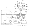
- FIG. 1 is a partial front view of a jigsaw puzzle to which the present invention is applied.
- FIG. 2 is a partial cross-sectional view of FIG. 1 cut along the line AA.
- FIG. 3 is a partial external view showing a state in which the piece 40 in FIG. 1 is removed.
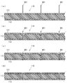
- FIG. 4 is an enlarged partial sectional view showing how the piece 40 is fitted to the piece 30.
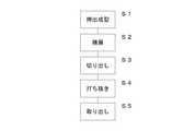
- FIG. 5 is a flow chart showing a manufacturing process of the jigsaw puzzle according to the manufacturing method 1 of the jigsaw puzzle of the present invention.
- FIG. 6 is a schematic view of a manufacturing line for manufacturing a jigsaw puzzle.
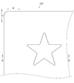
- FIG. 7 is a partial plan view of the base sheet.
- FIG. 1 is a partial front view of a jigsaw puzzle to which the present invention is applied.
- FIG. 2 is a partial cross-sectional view of FIG. 1 cut along the line AA.
- FIG. 3 is a partial external view showing a
- FIG. 8 is a partial cross-sectional view showing the process of cutting the base sheet, taken along the line BB in FIG.
- FIG. 9 is a partial plan view of the base sheet after being cut.
- FIG. 10 is a partial cross-sectional view showing the process of cutting the base sheet, taken along the line CC of FIG.
- FIG. 1 is a partial front view of a jigsaw puzzle to which the present invention is applied.
- FIG. 2 is a partial cross-sectional view of FIG. 1 cut along the line AA.
- FIG. 3 is a partial external view showing a state in which the piece 40 in FIG. 1 is removed.
- FIG. 4 is an enlarged partial sectional view showing how the piece 40 is fitted to the piece 30. As shown in FIG.
- the arrow H direction is referred to as “longitudinal direction”, and the arrow S direction is referred to as “horizontal direction”.
- the arrow ⁇ direction indicating the thickness direction of the jigsaw puzzle is referred to as “upward”, and the arrow ⁇ direction is referred to as “downward”.
- a state in which one piece is fitted to another adjacent piece will be described as a “fitted state”.
- a state in which one piece is not fitted to an adjacent other piece will be described as "non-fitting state”.
- the jigsaw puzzle 1 is formed of a plurality of pieces. As shown in FIG. 1 or 2, the jigsaw puzzle 1 in the present embodiment is formed in a single flat plate having a predetermined thickness in a fitted state in which all the pieces are fitted. Each piece is rectangular and in the shape of a rectangular parallelepiped having a predetermined thickness, and is formed with an engaging male portion or an engaging female portion. In the present embodiment, the rectangular parallelepiped shape of each piece has dimensions of about 13 mm ⁇ 13 mm in length and width and a thickness as thin as 1.0 mm.
- each piece is formed with an engaging male portion (convex portion) or an engaging female portion (concave portion) for combining other pieces on its side surface.
- the piece 40 has a substantially rectangular parallelepiped shape, and two engaging male portions 40m and 40m 'and two engaging female portions 40f and 40f' are formed on the side surfaces thereof.
- the engaging male portion 40m is formed in a substantially cylindrical shape.
- the engaging male portion 40m is provided outward from one side surface 40a of the piece 40.
- a portion of the peripheral wall of the engaging male portion 40m is integrated with a portion of the side surface 40a.
- the engaging male portion 40m ' is formed to project from one side surface 40b in the same manner as the engaging male portion 40m.
- the engagement female portion 40 f is formed inward of the piece 40 from a predetermined position of one side surface 40 c of the piece 40.
- the engagement female portion 40 f is a substantially circular shaped circular hole formed penetrating from the front surface to the rear surface of the piece 40.
- the engagement female portion 40 f is formed by notching one side surface 40 c of the piece 40 in a bayonet shape.
- the engagement female portion 40f ' is formed on one side surface 40d similarly to the engagement female portion 40f.
- the mating male part of one piece can be fitted to the mating female part of the other piece.
- the engagement male portion 10m of the piece 10 can be fitted to the engagement female portion 40f of the adjacent piece 40.
- an adjacent piece engaging male portion is fitted to the engaging female portion of one piece.
- the engaging male portion 20m of the adjacent piece 20 is fitted to the engaging female portion 10f of the piece 10.
- Adjacent pieces are formed in a shape in which the engaging male portion and the engaging female portion fit snugly. And, the shapes of the individual pieces are all formed so as to be slightly different, and not to be identical pieces. That is, the engaging male portion and the engaging female portion of the non-adjacent pieces are formed so as not to be fitted tightly.
- patterns such as pictures, pictures, figures and characters are formed. The player can complete the jigsaw puzzle 1 by arranging the pieces one by one, relying on the shape of the pieces and the patterns drawn on the pieces separated.
- the engaging male portion or the engaging female portion is not formed on the side surface corresponding to the edge portion. Further, in the pieces constituting the four corners of the completed jigsaw puzzle, the engaging male portion or the engaging female portion is not formed on the two side surfaces corresponding to the corner portions.
- FIG. 2 is a cross-sectional view of FIG. 1 taken along the line AA, but in order to make it easy to understand its appearance, it is schematically shown with a thickness.
- each piece is formed of three layers of a first hard layer, a soft layer and a second hard layer.
- the pieces 20, 30, 40 are formed of the first hard layers 21, 31, 41, the soft layers 22, 32, 42 and the second hard layers 23, 33, 43. From the upper direction to the lower direction, each piece is formed so as to be stacked in order of each first hard layer, each soft layer and each second hard layer.
- each of the first hard layers is made of elastically deformable polypropylene.
- Each first hard layer is formed of a thin film of polypropylene of about 0.1 mm.
- Each first hard layer is formed to be harder than each soft layer.
- patterns such as pictures, photographs, figures and characters are given.
- the pattern of each first hard layer is printed by an offset rotary printing press or a gravure rotary printing press. In the present embodiment, a pattern is printed on the surface of each first hard layer, but a pattern may be printed on the back surface.
- Each soft layer is a composition in which an elastically deformable thermoplastic synthetic resin and a thermoplastic elastomer are blended.
- each soft layer is a composition in which polypropylene and a thermoplastic olefin elastomer are blended.
- Each soft layer is formed of a sheet about 0.8 mm thick. The soft layer is thicker than the first hard layer.
- Each soft layer is softer than each first hard layer and each second hard layer. That is, since each soft layer is a composition in which a thermoplastic synthetic resin is mixed with a thermoplastic elastomer, each soft layer is softer than each first hard layer and each second hard layer made of only a thermoplastic synthetic resin.
- each second hard layer is used for each second hard layer.
- Each second hard layer is formed of a thin film of polypropylene of about 0.1 mm.
- Each second hard layer is formed to be harder than each soft layer.
- no pattern is printed on each second hard layer. However, pattern printing may be performed on the front surface or the back surface of each second hard layer.
- each first hard layer, each soft layer, and each second hard layer are formed in a color with high transparency through light, but at least a part is a transparent or semi-transparent portion. It is good.
- Each piece is an integral laminate in which each first hard layer, each soft layer and each second hard layer are laminated in order.
- Each piece is formed by punching out a base sheet 110 which is a laminate integrally formed by pressing a first hard layer 111, a soft layer 112 and a second hard layer 113 described later with a pressure roller. It is done.
- each piece a soft soft layer is sandwiched between hard first hard layers and hard second hard layers, so that warpage is less likely to occur, and a firm structure can be maintained even if it is thin. Is formed.
- a member constituting each soft layer is a composition in which polypropylene and a thermoplastic olefin elastomer are mixed, and a member constituting each first hard layer and each second hard layer is made of polypropylene There is. As described above, each piece is formed so that the soft layer and the first hard layer and the second hard layer are made of the same kind of members, so that the adhesion is good and firmly integrated.
- a star-shaped pattern is printed on the jigsaw puzzle 1.
- This star-shaped pattern is printed by a gravure rotary printing press.
- a star-shaped pattern is formed over the pieces 10, 20, 30 and 40. The pieces 10, 20, 30 and 40 are fitted to form a star-shaped pattern.
- the side surface of the piece and the peripheral wall of the engaging male portion are formed in a plurality of arcuate shapes (hereinafter referred to as “ring-like shapes”) that continuously undulate in cross section.
- the side surface of each first hard layer is formed in a bow shape so as to project outward of the piece from the end of the surface of each first hard layer to the end of the back surface.
- the side surface of each first hard layer is formed to have a predetermined angle in a cross sectional view, an inclined surface having a predetermined dimension, an arc, a parabola, or the like.
- the side surface of each soft layer is formed in a bow shape so as to project outward of the piece from the end of the surface of each soft layer to the end of the back surface.
- the side surface of each soft layer is formed to have a predetermined angle in a cross sectional view, an inclined surface having a predetermined dimension, an arc, a parabola or the like.
- each second hard layer is formed in a bow shape so as to protrude outward of the piece from the end of the surface of each second hard layer to the end of the back surface.
- the side surface of each second hard layer is formed in a plane such as a predetermined angle, a predetermined angle of inclination, a circular arc or a parabola in a cross sectional view.
- the side surfaces of the piece 40 and the peripheral wall of the engaging male portion 40a are formed by forming the side surfaces of the first hard layers, the soft layers, and the second hard layers into an arc shape, respectively. It is in the form of mountains.
- a first arcuate side surface 41 a which is a side surface of the first hard layer 41 is formed in a bow shape so as to project outward of the piece from the end of the surface of the first hard layer 41 to the end of the back surface.
- the first arcuate side surface 41a is formed of a gutter surface, a shear surface and a burr surface.
- the gutter surface is formed to bow downward from the surface of each layer.
- the cross section is formed continuously below the gutter surface.
- the sheared surface is created by the cutting edge of the punched vertical blade 801 or the punched horizontal blade 802 biting.
- the punched section is a surface that is scraped and formed smoothly on the side surface of the punching vertical blade 801 or the punching horizontal blade 802.
- the burr surface is formed to project downward from the back surface of each layer.
- the burred surface is a surface of a burr formed when the punching vertical blade 801 or the punching horizontal blade 802 pierces through each layer.
- the side surface of the soft layer 42 is also a second arcuate side surface 42 a formed in the same manner as the first arcuate side surface 41 a. Furthermore, the side surface of the second hard layer 43 is also a third arcuate side surface 43a formed in the same manner as the first arcuate side surface 41a.
- Each arcuate side surface of the piece 40 is formed to project slightly outward from the contour of the surface of the piece 40.
- the side surface of the piece 30 and the inner diameter of the engagement female portion 30 f are formed in a chain shape.
- the side surface of the first hard layer 31 is also a first arcuate side surface 31 a formed in the same manner as the first arcuate side surface 41 a.
- the side surface of the soft layer 32 is also a second arcuate side surface 32 a formed in the same manner as the second arcuate side surface 42 a.
- the side surface of the second hard layer 33 is also a third arcuate side surface 33a formed in the same manner as the third arcuate side surface 43a.
- Each arcuate side of the piece 30 is formed to project slightly outward from the contour of the surface of the piece 30.
- Each arcuate side surface is formed to be elastically deformed when a predetermined force or more is applied.
- the side surface of the one piece and the side surface of the adjacent other piece are elastically deformed and in close contact with each other.
- FIG. 4 (d) shows that the engagement male portion 40m of the piece 40 is fitted to the engagement female portion 30f of the piece 30.
- the first arcuate side surface 41a of the engagement male portion 40m and the first arcuate side surface 31a of the engagement female portion 30f But they are elastically deformed and in close contact with each other.
- the imaginary lines 41c, 42c and 43c shown in FIG. 4 (a) are imaginary lines showing the positions when the arcuate side surfaces are elastically deformed when the engagement male portion 40m is fitted to the engagement female portion 30f.
- the imaginary line 41c is positioned when the first arcuate side surface 41a is elastically deformed to be in close contact with the first arcuate side surface 31a when the engagement male portion 40m is fitted to the engagement female portion 30f. It is an imaginary line to show.
- imaginary lines 42c and 43c are imaginary lines showing the positions of the second arcuate side surface 42a and the third arcuate side surface 43a when they are elastically deformed.
- the imaginary lines 31c, 32c and 33c are imaginary lines showing the positions of the first arcuate side surface 31a, the second arcuate side surface 32a, and the third arcuate side surface 33a when they are elastically deformed.
- Each arcuate side surface elastically deforms to the position of each imaginary line when a predetermined or more force is applied in the process of fitting the engagement male portion 40m to the engagement female portion 30f.
- the engagement male portion 40m and the engagement female portion 30f are in a fitted state in a state in which the respective arcuate side surfaces are elastically deformed and in close contact.
- the game player compares the pieces of the jigsaw puzzle 1 separated into pieces with the piece pattern to search for ones that are adjacent to each other. As shown in FIG. 4A, it is confirmed that one engaging male portion 40m of the piece 40 can be fitted to one engaging female portion 30f of the piece 30, and the back surface portion of the engaging male portion 40m is It matches with the opening part of engagement female part 30f.
- the engagement male portion 40m With the back surface portion of the engagement male portion 40m aligned with the opening portion of the engagement female portion 30f, the engagement male portion 40m is pressed downward. As shown in FIG. 4B, when the engaging male portion 40m is pressed, the third arcuate side surface 43a abuts on the first arcuate side surface 31a, and elastically deforms when reaching a predetermined force or more. At this time, the first arcuate side surface 31a is also elastically deformed. That is, the third arcuate side surface 43a elastically deforms to the position of the imaginary line 43c shown in FIG. 4 (a). The first arcuate side surface 31a is elastically deformed to the position of an imaginary line 31c shown in FIG. 4 (a). As shown in FIG. 4B, the elastically deformed third arcuate side surface 43a and the first arcuate side surface 31a are in close contact with each other.
- the engaging male portion 40m is further pressed downward.
- the third arcuate side surface 43a abuts on the second arcuate side surface 32a, and elastically deforms when reaching a predetermined force or more.
- the second arcuate side surface 32a is also elastically deformed.
- the second arcuate side surface 42a abuts on the second arcuate side surface 32a and the first arcuate side surface 31a, and elastically deforms when a predetermined force or more is reached.
- the second arcuate side surface 32a and the first arcuate side surface 31a are also elastically deformed. That is, the third arcuate side surface 43a elastically deforms to the position of the imaginary line 43c shown in FIG. 4 (a).
- the first arcuate side surface 31a is elastically deformed to the position of an imaginary line 31c shown in FIG. 4 (a).
- the second arcuate side surface 32a elastically deforms to the position of the imaginary line 32c shown in FIG. 4 (a).
- the third arcuate side surface 43a and the second arcuate side surface 32a are in close contact with each other, and the second arcuate side surface 42a includes the second arcuate side surface 32a and the first arcuate side surface 31a.
- the engaging male portion 40m is further pressed downward.
- the third arcuate side surface 43a abuts on the third arcuate side surface 33a, and elastically deforms when reaching a predetermined force or more. At this time, the third arcuate side surface 33a is also elastically deformed.
- the second arcuate side surface 42a abuts on the second arcuate side surface 32a, and elastically deforms when a predetermined force or more is reached. At this time, the second arcuate side surface 32a is also elastically deformed.
- the first arcuate side surface 41a abuts on the first arcuate side surface 31a, and elastically deforms when reaching a predetermined force or more. At this time, the first arcuate side surface 31a is also elastically deformed. That is, the third arcuate side surface 43a elastically deforms to the position of the imaginary line 43c shown in FIG. 4 (a).
- the first arcuate side surface 31a is elastically deformed to the position of an imaginary line 31c shown in FIG. 4 (a). Furthermore, the second arcuate side surface 32a elastically deforms to the position of the imaginary line 32c shown in FIG. 4 (a).
- each imaginary line is an imaginary line which shows the position when each arcuate side is elastically deformed.
- the position of this imaginary line is only an example, and it goes without saying that this position changes depending on the state of the force applied to the piece in the fitted state.
- FIG. 5 is a flow chart showing a manufacturing process of the jigsaw puzzle according to the manufacturing method 1 of the jigsaw puzzle of the present invention.
- FIG. 6 is a schematic view of a manufacturing line for manufacturing a jigsaw puzzle.
- FIG. 7 is a partial plan view of the base sheet.
- FIG. 8 is a partial cross-sectional view showing the process of cutting the base sheet, taken along the line BB in FIG.
- FIG. 9 is a partial plan view of the base sheet after being cut.
- FIG. 10 is a partial cross-sectional view showing the process of cutting the base sheet, taken along the line CC of FIG.
- the soft sheet 102 is extruded by the extruder 200 (S1).
- the first hard sheet 101, the soft sheet 102, and the second hard sheet 103 are laminated to produce the laminated sheet 100 (S2).
- the laminated sheet 100 is cut to manufacture a base sheet 110 (S3).
- the base sheet 110 is punched out to manufacture a jigsaw puzzle 1 (S4). Take out the jigsaw puzzle 1 (S5).
- the jigsaw puzzle 1 is completed.
- the specific manufacturing method will be described.
- the jigsaw puzzle 1 utilizes the extruder 200, the feeding device 300, 300 ′, the drawing rollers 401, 402, 403, the pressure bonding device 500, the adjusting device 600, the cutting device 700 and the punching device 800. Manufactured.
- the extruder 200 is an apparatus for forming the soft sheet 102 which becomes each soft layer of each piece of the jigsaw puzzle 1.
- the feeding device 300 is a device for rolling out the first roll 101r on which the first hard sheet 101 is wound.
- the feeding device 300 ′ is a device for rolling out the second roll 103 r on which the second hard sheet 103 is wound.
- the take-up rollers 401, 402, and 403 are rollers for taking each sheet.
- the pressure bonding apparatus 500 is an apparatus for manufacturing the laminated sheet 100 by laminating the first hard sheet 101, the soft sheet 102, and the second hard sheet 103.
- the adjusting device 600 is a device for adjusting the thickness of the laminated sheet 100 and eliminating warpage.
- the cutting device 700 is a device that cuts the laminated sheet 100 into a predetermined size to manufacture the base sheet 110.
- the punching apparatus 800 is an apparatus for manufacturing the jig sheet puzzle 1 by punching the base sheet 110 into pieces.
- the process of extrusion molding is a process of manufacturing a flexible sheet using the extruder 200.
- the material of the flexible sheet 102 is mainly a thermoplastic synthetic resin and a thermoplastic elastomer.
- thermoplastic synthetic resin any one or more of polyvinyl chloride, polypropylene, polyethylene, polystyrene and polyethylene terephthalate are used.
- Thermoplastic elastomers exhibit rubber elasticity at normal temperature, and have the property of being plasticized and able to be molded like thermoplastic resins at high temperatures.
- thermoplastic elastomer any one or more of an olefin-based thermoplastic elastomer, a styrene-based thermoplastic elastomer, a polyester-based thermoplastic elastomer, and the like are used.
- the extruder 200 is supplied with a thermoplastic resin composition comprising polypropylene and a thermoplastic olefin elastomer.
- the blending of polypropylene and thermoplastic elastomer may be appropriately adjusted in accordance with the color, pattern and hardness of the jigsaw puzzle.
- a heating cylinder After melting and kneading in a heating cylinder, it is extruded by means of a screw and given a sheet-like shape by a die 201 at the tip end.
- thermoplastic elastomer in addition to the olefin elastomer, a styrene elastomer or a polyester elastomer may be used.
- a thermoplastic olefin-based elastomer Thermo Chemical made by Mitsubishi Chemical Co., Ltd. or Zerus made by that company may be used.
- Lavalon manufactured by Mitsubishi Chemical Corporation may be used as the thermoplastic styrene-based elastomer.
- thermoplastic polyester-based elastomer Primaloy manufactured by Mitsubishi Chemical Co., Ltd. may be used.
- the soft sheet 102 is molded by the extruder 200 in an uncured state which is almost solid but not completely cured immediately after being extruded.
- the soft sheet 102 is formed into a transparent sheet. At this time, the soft sheet 102 is extruded at about 250 ° C.
- the soft sheet 102 is formed into a sheet having a predetermined thickness (for example, 0.8 mm) and a predetermined width (for example, 1200 mm) using a rolling roller.
- the soft sheet 102 is taken by the take-up roller 401 and moves to the pressure bonding device 500.
- the take-up roller 401 is composed of a drive roller that is rotationally driven and a nip roller (which may be rotationally driven or may be rotated according to the drive roller without being rotationally driven).
- the take-up rollers 402 and 403 described later have the same configuration.
- the soft sheet 102 is moved to the pressure bonding device 500 in the uncured state. At this time, the flexible sheet 102 is moved to the crimping device 500 within a temperature range of about 150 to 160.degree. That is, the soft sheet 102 is moved to the pressure bonding apparatus 500 at a lower temperature than immediately after being extruded by the extruder 200.
- the soft sheet 102 is naturally cooled by moving from the extruder 200 to the pressure bonding apparatus 500.
- the soft sheet 102 is moved from the extruder 200 to the crimping device 500 by one take-up roller 401.
- movement may be performed by a plurality of take-up rollers.
- a plurality of take-up rollers may be provided between the extruder 200 and the pressure bonding device 500 in the vertical direction.
- the soft sheet 102 can lower its temperature by a short distance by advancing in a zigzag manner through a plurality of take-up rollers provided at the upper and lower sides.
- the process of lamination is a process of laminating the first hard sheet 101, the soft sheet 102 and the second hard sheet 103 and manufacturing the laminated sheet 100 by the pressure bonding apparatus 500.
- the first hard sheet 101 is formed by printing a pattern on a transparent transparent film.
- the transparent film is made of elastically deformable polypropylene and is a thin film of about 0.1 mm.
- the first hard sheet 101 is prepared to have the same width (for example, 1200 mm) as the soft sheet 102.
- the first hard sheet 101 is formed by printing a predetermined pattern on a transparent film by a gravure rotary printing machine.
- the first hard sheet 101 has a plurality of identical patterns printed at predetermined intervals in the longitudinal direction.
- the first hard sheet 101 has a pattern printed on one side.
- the printed first hard sheet 101 is taken up by a take-up device and made into a first roll 101r.
- the first roll 101 r is installed in the feeding device 300.
- the feeding device 300 includes a reel stand (not shown) and an in-feed device 301.
- the reel stand supports the first roll 101r so as to be rotatable.
- the in-feed device 301 makes the tension and the speed of the first hard sheet 101 fed out from the first roll 101 uniform.
- the first hard sheet 101 is fed out from the first roll 101 r toward the crimping device 500 by the feeding device 300.
- the second hard sheet 103 is formed of a transparent film.
- the transparent film is made of elastically deformable polypropylene and is a thin film of about 0.1 mm.
- the second hard sheet 103 is prepared to have the same width (for example, 1200 mm) as the soft sheet 102.
- the second hard sheet 103 is taken up by a take-up device to form a second roll 103r.
- the second roll 103r is installed in the feeding device 300 '. Similar to the feeding device 300, the feeding device 300 'includes a reel stand (not shown) and an infeed device 301'.
- the second hard sheet 103 is fed out from the second roll 103r toward the crimping device 500 by the feeding device 300 '.
- the crimping device 500 is configured of a pair of crimping rollers 501 and 502.
- the pressure roller 501 is a roller that is rotationally driven.
- the pressure roller 502 may be a roller that is rotationally driven, or may be a roller that is rotated according to the pressure roller 501 without being rotationally driven.
- a nip portion is provided between the pair of pressure rollers 501 and 502 at a predetermined interval for passing the laminated sheet 100. In the present embodiment, the nip portions are formed at intervals of, for example, 1.0 mm.
- the first hard sheet 101 is aligned with one side of the soft sheet 102, and the second hard sheet 103 is aligned with the other side of the soft sheet 102 and guided to the nip portion. That is, the first hard sheet 101, the soft sheet 102, and the hard sheet 103 are guided to the nip portion in the order of being stacked from the top. In the state in which the first hard sheet 101, the soft sheet 102, and the hard sheet 103 are stacked in order, the thickness is 1.0 mm.
- the first hard sheet 101, the soft sheet 102, and the second hard sheet 103 are pressed at a predetermined pressure by passing through the nip portion in a laminated state, and a laminated sheet 100 having a thickness of 1.0 mm is manufactured. Ru. More specifically, the first hard sheet 101 and the second hard sheet 102 are pressurized at a predetermined pressure at the nip portion in a state in which the uncured soft sheet 102 is sandwiched. At this time, the soft sheet 102 in the uncured state is in a temperature range of about 150 ° C. to 160 ° C.
- the pressurized first hard sheet 101, the soft sheet 102, and the second hard sheet 102 are in close contact with each other.
- this close contact state when the temperature of the soft sheet 102 is lowered and it is completely cured, it becomes a laminated sheet 100 in which the first hard sheet 101, the soft sheet 102 and the second hard sheet are integrated. Therefore, the laminated sheet 100 is manufactured by integrally bonding the first hard sheet 101 and the second hard sheet 102 to the soft sheet 102 without requiring an adhesive or the like.
- the soft sheet 102, the first hard sheet 101, and the second hard sheet are made of the same kind of members, so they have good adhesion and are firmly integrated.
- the laminated sheet 100 since the soft flexible sheet 102 is sandwiched between the hard first hard sheet 101 and the hard second hard sheet 103, a warp or the like is less likely to occur, and a firm configuration can be maintained even if it is thin. It is formed in a sheet.
- the laminated sheet 100 is picked up by the pickup roller 402 and moved to the adjusting device 600.
- the adjusting device 600 includes adjusting rollers 601 and 602.
- the adjustment roller 601 is composed of a drive roller which is rotationally driven and a nip roller (which may be rotationally driven or may be rotated according to the drive roller without being rotationally driven).
- the adjustment roller 602 also has the same configuration.
- the adjustment roller 601 and the adjustment roller 602 are disposed at different heights.
- the adjustment roller 601 is disposed at a position higher than the take-up rollers 402 and 403.
- the adjustment roller 601 is disposed at a lower position than the take-up rollers 402 and 403.
- the laminated sheet 100 bends upward when passing through the adjustment roller 601 and moves while bending downward when passing through the adjustment roller 602.
- the laminated sheet 100 is adjusted to a flat plane free from warpage by reducing the internal stress by passing the adjusting rollers 601 and 602 arranged at different heights.
- the laminated sheet 100 which has passed through the adjusting device 600 is taken by the take-up roller 403 and moved to the cutting device 700.
- the laminated sheet 100 is cut into a rectangular shape of a predetermined size by the cutting blade 701 of the cutting device 700 to form the base sheet 110.
- the jigsaw puzzle of the present embodiment is cut out in a rectangular shape, it is needless to say that it may be cut out in another shape.
- the base sheet 110 is formed by integrating the first hard layer 111, the soft layer 112, and the second hard layer 113.
- the first hard layer 111 is obtained by cutting the first hard sheet 101.
- the soft layer 112 is obtained by cutting the soft sheet 102.
- the second hard layer 113 is obtained by cutting the second hard sheet 101.
- the base sheet 110 is punched by a punching device 800 to manufacture the jigsaw puzzle 1 composed of a plurality of pieces.
- the punching device 800 is provided with a punching vertical blade 801 and a punching horizontal blade 802.
- the punching vertical blade 801 and the punching horizontal blade 802 are blades for dividing the base sheet 110 into a plurality of pieces.
- the base sheet 110 is divided by the punching vertical blade 801 and the punching horizontal blade 802 to form an engagement male portion or an engagement female portion on each piece.
- a plurality of punching vertical blades 801 are provided at predetermined intervals so as to be substantially parallel to the longitudinal direction.
- a plurality of punching horizontal blades 802 are provided at predetermined intervals so as to be substantially parallel to the lateral direction.
- the base sheet 110 may be placed in a mold that matches the dimensions of the base sheet 110 so as not to shift in the process of being punched by the punched vertical blade 801 or the punched horizontal blade 802. Next, the process of forming the jigsaw puzzle 1 by punching out the base sheet 110 according to FIGS. 7 to 10 will be described in detail.
- the base sheet 110 has a pattern printed on its surface.
- the punching vertical blade 801 is first applied to the surface of the first hard layer 111.
- the punching vertical blade 801 is pressed downward while being in contact with the surface of the first hard layer 111.
- the first hard layer 111 elastically deforms when the punching vertical blade 801 is pressed with a predetermined force or more. At this time, a gutter surface is formed on the first hard layer 111.
- the punching vertical blade 801 punches the first hard layer 111.
- a sheared surface and a burred surface are formed on the first hard layer 111. The sagittal, shear and burr surfaces become the first arcuate side of each piece (see FIG. 4).
- the soft layer 112 elastically deforms when the punching vertical blade 801 is pressed with a predetermined force or more. At this time, a soft surface is formed on the soft layer 112. Furthermore, when the punching vertical blade 801 is pressed, the punching vertical blade 801 punches the soft layer 112. At this time, a shear surface and a burr surface are formed on the soft layer 112. The sagittal, shear and burr surfaces become the second arcuate side of each piece (see FIG. 4).
- the second hard layer 113 elastically deforms when the punching vertical blade 801 is pressed with a predetermined force or more. At this time, a gutter surface is formed on the second hard layer 113. Furthermore, when the punching vertical blade 801 is pressed, the punching vertical blade 801 punches the second hard layer 113. At this time, a shear surface and a burr surface are formed on the second hard layer 113. The sagittal, shear and burr surfaces become the third arcuate side of each piece (see FIG. 4).
- the punching vertical blade 801 is stopped at such a degree that the cutting edge slightly protrudes from the back surface of the second hard layer 113. Thereafter, the punching vertical blade 801 is moved upward and pulled out of the base sheet 110. At this time, the sheared surfaces of the first hard layer 111, the soft layer 112, and the second hard layer 113 are smoothed by scraping the punched vertical blade 801. As shown in FIG. 9, the base sheet 110 is cut in the longitudinal direction by being punched by the punching vertical blade 801.
- the punched horizontal blade 802 is applied to the surface of the first hard layer 111.
- the punching horizontal blade 802 is pressed downward while being in contact with the surface of the first hard layer 111.
- the first hard layer 111 is elastically deformed when the punching horizontal blade 802 is pressed with a predetermined force or more. At this time, a gutter surface is formed on the first hard layer 111.
- the punching horizontal blade 802 punches the first hard layer 111.
- a sheared surface and a burred surface are formed on the first hard layer 111. The sagittal, shear and burr surfaces become the first arcuate side of each piece (see FIG. 4).
- the soft layer 112 elastically deforms when the punching horizontal blade 802 is pressed with a predetermined force or more. At this time, a soft surface is formed on the soft layer 112. Furthermore, when the punching horizontal blade 802 is pressed, the punching horizontal blade 802 punches the soft layer 112. At this time, a shear surface and a burr surface are formed on the soft layer 112. The sagittal, shear and burr surfaces become the second arcuate side of each piece (see FIG. 4).
- the second hard layer 113 elastically deforms when the punching horizontal blade 802 is pressed with a predetermined force or more. At this time, a gutter surface is formed on the second hard layer 113. Furthermore, when the punching horizontal blade 802 is pressed, the punching horizontal blade 802 punches the second hard layer 113. At this time, a shear surface and a burr surface are formed on the second hard layer 113. The sagittal, shear and burr surfaces become the third arcuate side of each piece (see FIG. 4).
- the punching horizontal blade 802 is stopped at such an extent that the cutting edge slightly protrudes from the back surface of the second hard layer 113. Thereafter, the punching horizontal blade 802 is moved upward and pulled out of the base sheet 110. At this time, the sheared surfaces of the first hard layer 111, the soft layer 112, and the second hard layer 113 are smoothed by scraping the punched vertical blade 801. As shown in FIG. 1, the base sheet 110 is cut in the lateral direction by being punched by the punched horizontal blade 802, and the jigsaw puzzle 1 is completed.
- the pattern is printed on one side of the first hard sheet 101, but the pattern may be printed on the other side. That is, it goes without saying that the pattern may be printed on one side and / or the other side.
- the second hard sheet 103 is not printed with a pattern, but may also be printed with a pattern on one side and / or the other side.
- each piece is not limited to the present embodiment, and may have a thickness of 0.8 to 2.0 mm, and the thickness of each of the first hard layer, the second hard layer, and the soft layer may be appropriately changed accordingly Good.
- each first hard layer and each second hard layer may have a thickness of 0.1 to 0.2 mm, and the soft layer may have a thickness of 0.6 to 1.6 mm.
- the design may be improved by inserting metal pieces, beads, gems, lams and the like in the jigsaw puzzle.
Landscapes
- Engineering & Computer Science (AREA)
- Multimedia (AREA)
- Toys (AREA)
Priority Applications (2)
| Application Number | Priority Date | Filing Date | Title |
|---|---|---|---|
| US14/123,463 US9308438B2 (en) | 2011-06-03 | 2012-06-01 | Jigsaw puzzle and manufacturing method thereof |
| EP12792289.6A EP2716336B1 (en) | 2011-06-03 | 2012-06-01 | Jigsaw puzzle and manufacturing method thereof |
Applications Claiming Priority (2)
| Application Number | Priority Date | Filing Date | Title |
|---|---|---|---|
| JP2011-125358 | 2011-06-03 | ||
| JP2011125358A JP5193334B2 (ja) | 2011-06-03 | 2011-06-03 | ジグソーパズルとその製造方法 |
Publications (1)
| Publication Number | Publication Date |
|---|---|
| WO2012165631A1 true WO2012165631A1 (ja) | 2012-12-06 |
Family
ID=47259479
Family Applications (1)
| Application Number | Title | Priority Date | Filing Date |
|---|---|---|---|
| PCT/JP2012/064324 Ceased WO2012165631A1 (ja) | 2011-06-03 | 2012-06-01 | ジグソーパズルとその製造方法 |
Country Status (4)
| Country | Link |
|---|---|
| US (1) | US9308438B2 (enExample) |
| EP (1) | EP2716336B1 (enExample) |
| JP (1) | JP5193334B2 (enExample) |
| WO (1) | WO2012165631A1 (enExample) |
Families Citing this family (18)
| Publication number | Priority date | Publication date | Assignee | Title |
|---|---|---|---|---|
| JP5193334B2 (ja) * | 2011-06-03 | 2013-05-08 | 株式会社ゲートウェイアーチ | ジグソーパズルとその製造方法 |
| HK1170366A2 (en) * | 2012-09-12 | 2013-02-22 | 怡人国际(香港)有限公司 | A puzzle and its manufacturing process |
| JP6139200B2 (ja) * | 2013-03-21 | 2017-05-31 | 株式会社ゲートウェイアーチ | 組立玩具及び組立玩具製造方法 |
| US9724618B2 (en) | 2013-07-18 | 2017-08-08 | Palziv Ltd. | Compressible vertical connector |
| WO2015191637A1 (en) * | 2014-06-09 | 2015-12-17 | Phumble LLC | Puzzle creation and sharing over a network |
| JP6419141B2 (ja) * | 2016-12-09 | 2018-11-07 | 株式会社ゲートウェイアーチ | 組立玩具用ピースの製造方法 |
| JP2019187561A (ja) * | 2018-04-19 | 2019-10-31 | 株式会社ゲートウェイアーチ | ジグソーパズル |
| KR102156657B1 (ko) * | 2018-10-26 | 2020-09-16 | 주식회사 오티이 | 완성 형상이 유지되는 점착식 플라스틱 직소퍼즐 제조방법 |
| DE202019002113U1 (de) * | 2019-05-14 | 2020-08-17 | Lars Köthe | Mehrschichtige Beschichtung für Substratoberflächen |
| US11498357B2 (en) * | 2019-06-20 | 2022-11-15 | Certainteed Llc | Randomized surface panel kit and surface panel system |
| JP7370562B2 (ja) * | 2019-06-26 | 2023-10-30 | 株式会社ゲートウェイアーチ | ジグソーパズル |
| US11198056B2 (en) | 2019-08-14 | 2021-12-14 | Thomas Greenawalt | Multiple level jigsaw puzzle |
| USD958693S1 (en) * | 2020-02-20 | 2022-07-26 | Mouna Rebeiz | Sculpture |
| JP7283753B2 (ja) * | 2020-02-25 | 2023-05-30 | 昌秀 神田 | 透明ジグソーパズル |
| DE102021113338A1 (de) | 2021-05-21 | 2022-11-24 | puzzleYOU GmbH | System zur Aufbewahrung von Puzzleteilen, Verkaufseinheit eines Puzzles und Verfahren zur Herstellung eines Puzzles |
| US12544652B2 (en) | 2021-05-21 | 2026-02-10 | puzzleYOU GmbH | System for storage of puzzle pieces, sales unit of a puzzle and a method for manufacturing a puzzle |
| US20220395997A1 (en) * | 2021-06-14 | 2022-12-15 | puzzle & play GmbH | Method for producing a puzzle and separating device for the same |
| US20230277922A1 (en) * | 2022-03-04 | 2023-09-07 | Mark Zadvinskis | No-flip jigsaw puzzle |
Citations (5)
| Publication number | Priority date | Publication date | Assignee | Title |
|---|---|---|---|---|
| JPS5937219B2 (ja) * | 1980-04-18 | 1984-09-08 | 三和化學株式会社 | 合成樹脂製緩衝材の製造法 |
| JPH0156907B2 (enExample) * | 1982-07-03 | 1989-12-01 | Nitto Boseki Co Ltd | |
| JP3047284U (ja) * | 1997-07-11 | 1998-04-10 | 株式会社大一企画 | 浴室用知育玩具 |
| JP2006055290A (ja) * | 2004-08-18 | 2006-03-02 | Gateway Arch:Kk | フィット音を発するジグソーパズル |
| JP2010060737A (ja) * | 2008-09-02 | 2010-03-18 | Nobumasa Mizuno | ジグゾーパズル地図 |
Family Cites Families (15)
| Publication number | Priority date | Publication date | Assignee | Title |
|---|---|---|---|---|
| US3174893A (en) * | 1961-01-17 | 1965-03-23 | Idella R Church | Simulated ceramic tile-like mosaic construction |
| US4824112A (en) * | 1987-05-04 | 1989-04-25 | Ray Roy | Three-dimensional puzzle building |
| US5257785A (en) * | 1991-06-27 | 1993-11-02 | Epoch Co., Ltd. | Jigsaw puzzle |
| US6086067A (en) * | 1993-12-31 | 2000-07-11 | Distributions Muralex Inc. | Three-dimensional puzzle |
| JP3734587B2 (ja) * | 1997-03-14 | 2006-01-11 | 本田技研工業株式会社 | ポリプロピレン系樹脂製外板及びその製造方法 |
| US6141851A (en) * | 1998-01-02 | 2000-11-07 | Williamson Printing Corporation | Apparatus for forming a hardboard picture puzzle including multiple puzzle pieces |
| US20020093137A1 (en) * | 2001-01-16 | 2002-07-18 | Enko Frederick A. | Die-cutting system for a jigsaw puzzle |
| EP1285745A1 (en) * | 2001-01-16 | 2003-02-26 | Daicel-Degussa Ltd. | Composite and process for producing the same |
| US6547243B2 (en) * | 2001-02-02 | 2003-04-15 | Arthur William Juenger | Portable three dimensional puzzles |
| US6777482B2 (en) * | 2002-04-04 | 2004-08-17 | Owens Corning Fiberglas Technology, Inc. | Alternative polyolefin composite veil/compatibilizing mat material |
| JP5123468B2 (ja) * | 2005-06-16 | 2013-01-23 | 株式会社ユポ・コーポレーション | カード用紙、その製造方法及びトランプカード |
| US7677568B1 (en) * | 2008-09-19 | 2010-03-16 | Pigment & Hue, Inc. | Two-sided puzzle and box assembly |
| US8490976B2 (en) * | 2009-02-02 | 2013-07-23 | Cardin Flora Salgado | Double-sided jigsaw puzzle and method of making the same |
| JP5193334B2 (ja) * | 2011-06-03 | 2013-05-08 | 株式会社ゲートウェイアーチ | ジグソーパズルとその製造方法 |
| HK1170366A2 (en) * | 2012-09-12 | 2013-02-22 | 怡人国际(香港)有限公司 | A puzzle and its manufacturing process |
-
2011
- 2011-06-03 JP JP2011125358A patent/JP5193334B2/ja active Active
-
2012
- 2012-06-01 US US14/123,463 patent/US9308438B2/en active Active
- 2012-06-01 WO PCT/JP2012/064324 patent/WO2012165631A1/ja not_active Ceased
- 2012-06-01 EP EP12792289.6A patent/EP2716336B1/en active Active
Patent Citations (5)
| Publication number | Priority date | Publication date | Assignee | Title |
|---|---|---|---|---|
| JPS5937219B2 (ja) * | 1980-04-18 | 1984-09-08 | 三和化學株式会社 | 合成樹脂製緩衝材の製造法 |
| JPH0156907B2 (enExample) * | 1982-07-03 | 1989-12-01 | Nitto Boseki Co Ltd | |
| JP3047284U (ja) * | 1997-07-11 | 1998-04-10 | 株式会社大一企画 | 浴室用知育玩具 |
| JP2006055290A (ja) * | 2004-08-18 | 2006-03-02 | Gateway Arch:Kk | フィット音を発するジグソーパズル |
| JP2010060737A (ja) * | 2008-09-02 | 2010-03-18 | Nobumasa Mizuno | ジグゾーパズル地図 |
Also Published As
| Publication number | Publication date |
|---|---|
| JP2012249851A (ja) | 2012-12-20 |
| JP5193334B2 (ja) | 2013-05-08 |
| EP2716336A1 (en) | 2014-04-09 |
| US9308438B2 (en) | 2016-04-12 |
| EP2716336B1 (en) | 2018-03-07 |
| EP2716336A4 (en) | 2014-12-17 |
| US20140246832A1 (en) | 2014-09-04 |
Similar Documents
| Publication | Publication Date | Title |
|---|---|---|
| JP5193334B2 (ja) | ジグソーパズルとその製造方法 | |
| JP2012249851A5 (enExample) | ||
| CA2735897C (en) | Thin film high definition dimensional image display device and methods of making same | |
| EP2803463A1 (de) | Funktionsträger mit Tastenfunktionen | |
| CN101600313A (zh) | 外壳及其制作方法 | |
| CN101332641A (zh) | 一种模内标签制造工艺 | |
| JP6419141B2 (ja) | 組立玩具用ピースの製造方法 | |
| JP2017111397A (ja) | シート積層造型用型紙およびシート積層造型用型紙の製造方法 | |
| JP6139200B2 (ja) | 組立玩具及び組立玩具製造方法 | |
| CN214522591U (zh) | 金属片与泡棉、细窄麦拉边框复合组件生产用压合设备 | |
| CN1669830A (zh) | 特殊装饰印刷金属板和其制造方法 | |
| EP2441577B1 (en) | In-mold label and method for producing the same | |
| JP2007118597A (ja) | 化粧シート及びその製造方法並びに化粧シート付射出成形品 | |
| KR100361436B1 (ko) | 기계적 문양이 가공된 박층 필름의 제조 방법 및 그 장치 | |
| CN201936025U (zh) | 一种印刷产品 | |
| KR20170110996A (ko) | 3d 홀로그램 입체 라벨 제조방법 | |
| WO2007037363A1 (ja) | 化粧シート及びその製造方法並びに化粧シート付射出成形品 | |
| TWI717284B (zh) | 立體浮凸電鍍貼紙的製造方法與結構 | |
| US20070227412A1 (en) | Process for forming a table top | |
| JP7283753B2 (ja) | 透明ジグソーパズル | |
| US20090110851A1 (en) | Melamine resin container having three-dimensional shape and manufacturing method thereof | |
| JP5640177B2 (ja) | ジグソーパズルとその製造方法 | |
| JP2006305898A (ja) | 樹脂成形品の製造方法および樹脂成形品 | |
| US11999095B2 (en) | Bottle manufacturing method and bottle | |
| WO2022209328A1 (ja) | インサート成形用加飾フィルム、インサート成形用加飾フィルムの製造方法及び樹脂成形品の製造方法 |
Legal Events
| Date | Code | Title | Description |
|---|---|---|---|
| 121 | Ep: the epo has been informed by wipo that ep was designated in this application |
Ref document number: 12792289 Country of ref document: EP Kind code of ref document: A1 |
|
| NENP | Non-entry into the national phase |
Ref country code: DE |
|
| WWE | Wipo information: entry into national phase |
Ref document number: 14123463 Country of ref document: US |