WO2012165014A1 - モータグレーダ - Google Patents
モータグレーダ Download PDFInfo
- Publication number
- WO2012165014A1 WO2012165014A1 PCT/JP2012/058097 JP2012058097W WO2012165014A1 WO 2012165014 A1 WO2012165014 A1 WO 2012165014A1 JP 2012058097 W JP2012058097 W JP 2012058097W WO 2012165014 A1 WO2012165014 A1 WO 2012165014A1
- Authority
- WO
- WIPO (PCT)
- Prior art keywords
- plate
- leg
- frame
- motor grader
- annular portion
- Prior art date
- Legal status (The legal status is an assumption and is not a legal conclusion. Google has not performed a legal analysis and makes no representation as to the accuracy of the status listed.)
- Ceased
Links
Images


Classifications
-
- E—FIXED CONSTRUCTIONS
- E02—HYDRAULIC ENGINEERING; FOUNDATIONS; SOIL SHIFTING
- E02F—DREDGING; SOIL-SHIFTING
- E02F3/00—Dredgers; Soil-shifting machines
- E02F3/04—Dredgers; Soil-shifting machines mechanically-driven
- E02F3/76—Graders, bulldozers, or the like with scraper plates or ploughshare-like elements; Levelling scarifying devices
- E02F3/7636—Graders with the scraper blade mounted under the tractor chassis
-
- E—FIXED CONSTRUCTIONS
- E02—HYDRAULIC ENGINEERING; FOUNDATIONS; SOIL SHIFTING
- E02F—DREDGING; SOIL-SHIFTING
- E02F3/00—Dredgers; Soil-shifting machines
- E02F3/04—Dredgers; Soil-shifting machines mechanically-driven
- E02F3/76—Graders, bulldozers, or the like with scraper plates or ploughshare-like elements; Levelling scarifying devices
- E02F3/7636—Graders with the scraper blade mounted under the tractor chassis
- E02F3/7645—Graders with the scraper blade mounted under the tractor chassis with the scraper blade being pivotable about a horizontal axis disposed parallel to the blade
-
- E—FIXED CONSTRUCTIONS
- E02—HYDRAULIC ENGINEERING; FOUNDATIONS; SOIL SHIFTING
- E02F—DREDGING; SOIL-SHIFTING
- E02F3/00—Dredgers; Soil-shifting machines
- E02F3/04—Dredgers; Soil-shifting machines mechanically-driven
- E02F3/76—Graders, bulldozers, or the like with scraper plates or ploughshare-like elements; Levelling scarifying devices
- E02F3/80—Component parts
- E02F3/84—Drives or control devices therefor, e.g. hydraulic drive systems
- E02F3/844—Drives or control devices therefor, e.g. hydraulic drive systems for positioning the blade, e.g. hydraulically
Definitions
- the present invention relates to a motor grader provided with a working machine.
- a motor grader includes a frame, a work machine disposed below the frame, an annular lifter guide attached to the frame, and a lift cylinder coupled to the lifter guide and the work machine (See, for example, Patent Document 1).
- the present invention is made in view of the above-mentioned situation, and it aims at providing a motor grader which can improve junction intensity of a lifter guide and a frame.
- a motor grader includes a frame, a work machine disposed below the frame, a lifter guide surrounding the frame and joined to the frame, a lifter bracket surrounding the lifter guide, and a lifter bracket And a lift cylinder for driving the work machine.
- the lifter guide has an annular portion surrounding the outer periphery of the frame, and a first leg continuous with the inner periphery of the annular portion and projecting from the annular portion in a side view and having an outer edge joined to the frame.
- the lifter guide since the lifter guide has the first leg, it is possible to increase the joint range (i.e., weld line length) between the frame and the lifter guide it can. Therefore, the bonding strength between the lifter guide and the frame can be improved.
- a motor grader relates to the first aspect, wherein the frame extends in the vehicle width direction, an upper plate extending in the vehicle width direction, a lower plate facing the upper plate, and vertically extending It is comprised by the 1st side plate pinched
- the widths of both ends in the vehicle width direction of the upper plate and the lower plate are equal to the widths of both ends in the vehicle width direction of the first side plate and the second side plate.
- the outer edge of the first leg portion is joined to the side surface of the upper plate, the side surface of the first side plate, and the side surface of the lower plate.
- the first leg portion is formed of the upper plate and the lower plate by making the widths of the upper plate and the lower plate equal to the widths of the first side plate and the second side plate. Bonding to the plate has been realized. As a result, since the joining range of the frame and the lifter guide can be further enlarged, the joining strength between the lifter guide and the frame can be further improved.
- a motor grader according to a third aspect of the present invention relates to the second aspect, wherein the first side plate is a body plate disposed inward of one end of the upper plate and the lower plate in the vehicle width direction, and the outer side of the body plate And a reinforcing plate disposed on the first side plate.
- the widths of the upper and lower plates and the widths of the first and second side plates are equalized by inserting the reinforcing plate. Therefore, not only the joint range between the frame and the lifter guide can be further increased, but also the strength of the frame itself can be improved.
- a motor grader relates to the second aspect, wherein the first side plate is constituted by a main body plate disposed inward of one end in the vehicle width direction of each of the upper and lower plates.
- the upper plate has an upper notch formed in the joint portion, and the lower plate has a lower notch formed correspondingly to the upper notch.
- the motor grader of the fourth aspect of the present invention by forming the upper and lower notches, the widths of the upper and lower plates and the widths of the first and second side plates and Can be equal. Therefore, the joint range between the frame and the lifter guide can be further enlarged, and the weight of the frame itself can be reduced.
- a motor grader according to a fifth aspect of the present invention relates to any one of the second to fourth aspects, wherein the first leg projects forward and backward in a side view.
- the annular portion can be supported with good balance from the front and rear by the first leg, and the bonding range between the frame and the lifter guide can be further enlarged. Therefore, the bonding strength between the lifter guide and the frame can be further improved.
- a motor grader relates to any one of the second to fifth aspects, wherein the first leg is a first upper leg joined to the side surface of the upper plate and the side surface of the first side plate. And a first lower leg joined to the side surface of the first side plate and the side surface of the lower plate. The first upper leg and the first lower leg are spaced apart from each other.
- the lifter guide can be firmly supported by the first upper leg and the first lower leg with respect to the vertically swinging frame.
- stress may be applied to the joint portion unevenly as compared with the case where the first upper leg and the first lower leg are uniformly continued. It can be suppressed. Therefore, since it can suppress that stress is applied to the junction part of a flame
- a motor grader according to a seventh aspect of the present invention relates to the sixth aspect, wherein the width of each of the first upper leg and the first lower leg is narrower as it goes away from the annular portion.
- the motor grader concerning the 7th mode of the present invention it can control that big stress is applied to the 1st upper leg and the 1st lower leg by narrowing leg width gradually.
- a motor grader according to an eighth aspect of the present invention relates to the sixth or seventh aspect, wherein the thickness of each of the first upper leg and the first lower leg is thinner as it goes away from the annular portion.
- the motor grader concerning the 8th mode of the present invention, it can control that big stress is applied to the 1st upper leg and the 1st lower leg by making a leg thickness thin gradually.
- a motor grader relates to any one of the first to eighth aspects, wherein the lifter guide is continuous with the inner periphery of the annular portion and protrudes from the annular portion in side view and has an outer edge And a second leg joined to the frame. The second leg is provided on the opposite side of the first leg across the frame.
- the annular portion can be supported with good balance from the left and right by the first leg and the second leg, and the joint range between the frame and the lifter guide can be further enlarged. Therefore, the bonding strength between the lifter guide and the frame can be further improved.
- a motor grader according to a tenth aspect of the present invention relates to the ninth aspect, wherein the second leg protrudes in the front and back of the annular portion in a side view.
- the annular portion can be supported with good balance from the front and rear by the second leg, and the bonding range between the frame and the lifter guide can be further enlarged. Therefore, the bonding strength between the lifter guide and the frame can be further improved.
- a motor grader according to an eleventh aspect of the present invention relates to the ninth or tenth aspect, wherein the second leg is a second upper leg joined to the side surface of the upper plate and the side surface of the second side plate; And a second lower leg joined to the side surface of the two side plates and the side surface of the lower plate.
- the second upper leg and the second lower leg are separated from each other.
- the motor grader according to the eleventh aspect of the present invention it is possible to further suppress uneven stress on the joint portion between the frame and the lifter guide, so that breakage of the joint between the lifter guide and the frame is further caused. It can be suppressed.
- a motor grader according to a twelfth aspect of the present invention relates to the eleventh aspect, wherein the width of each of the second upper leg and the second lower leg is narrower as it goes away from the annular portion.
- the motor grader concerning the 12th mode of the present invention it can control that big stress is applied to the 2nd upper leg and the 2nd lower leg by narrowing leg width gradually.
- a motor grader according to a thirteenth aspect of the present invention relates to the eleventh or twelfth aspect, wherein the thickness of each of the second upper leg and the second lower leg is thinner as it is separated from the annular portion.
- the motor grader concerning the 13th mode of the present invention, it can control that big stress is applied to the 2nd upper leg and the 2nd lower leg by making a leg thickness thin gradually.
- FIG. 1 is a side view showing an overall configuration of a motor grader.
- the disassembled perspective view which shows the structure around a lifter guide.
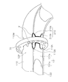
- AA sectional drawing of FIG. BB sectional drawing of FIG. The perspective view of the connection part of a frame and a lifter guide.
- FIG. 1 is a side view showing the overall configuration of a motor grader 100 according to the embodiment.
- “upper”, “lower”, “left”, “right”, “front” and “rear” are terms based on the operator seated in the driver's seat.
- the motor grader 100 includes a frame 10, front wheels 20, rear wheels 30, a cab 40, a drawbar 50, blades 60, lifter guides 70, lifter brackets 75, and a pair of lifts.
- a cylinder 80 and a shift cylinder 90 are provided.
- the frame 10 is composed of a front frame 11 and a rear frame 12.
- the front frame 11 supports the drawbar 50 and the blade 60.
- the rear frame 12 supports an engine, a hydraulic pump, etc. (not shown).
- the front wheel 20 is attached to the front end of the frame 10.
- the rear wheel 30 is attached to the rear end of the frame 10.
- the front wheel 20 includes a pair of left and right traveling wheels, and the rear wheel 30 includes two pairs of left and right traveling wheels, but the present invention is not limited thereto.
- the cab 40 is disposed on the frame 10.
- the drawbar 50 is attached to the front end of the frame 10 so as to be able to swing up and down.
- the blade 60 is fixed to the rear end of the drawbar 50.
- the lifter guide 70 is an annular member joined (welded) to the frame 10.
- the lifter bracket 75 is a frame surrounding the lifter guide 70.
- a pair of lift cylinders 80 and shift cylinders 90 are attached to the lifter bracket 75. The configuration around the lift guide 70 will be described later.
- the drawbar 50 and the blade 60 constitute a working machine disposed below the frame 10.
- a pair of lift cylinders 80 (only the right lift cylinder is shown in FIG. 1) is connected to the drawbar 50 and the lifter bracket 75.
- the shift cylinder 90 is connected to the drawbar 50 and the lifter bracket 75.
- the drawbar 50 and the blade 60 are driven to the left and right according to the expansion and contraction of the shift cylinder 90.
- FIG. 2 is an exploded perspective view showing the configuration around the lifter guide 70. As shown in FIG.
- the lifter guide 70 is joined to a predetermined position of the frame 10.
- a portion of the frame 10 to which the lifter guide 70 is to be joined is shown as a joint portion 10P.
- the joint structure of the frame 10 and the lifter guide 70 will be described later.
- the lifter bracket 75 has an upper frame 75a and a lower frame 75b.
- the upper frame 75 a and the lower frame 75 b are each formed in a semicircular ring shape, and are connected to each other so as to sandwich the lifter guide 70.
- a pair of lift cylinders 80 are attached to the upper frame 75a, and a shift cylinder 90 is attached to the lower frame 75b.
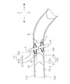
- FIG. 3 is a side view of the joint portion 10P.
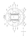
- FIG. 4 is a cross-sectional view taken along line AA of FIG.
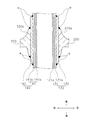
- FIG. 5 is a cross-sectional view taken along the line BB in FIG.
- the welding part w which joins the flame
- the weld w is a so-called bead.
- the frame 10 is configured by an upper plate 110, a lower plate 120, a first side plate 130, and a second side plate 140, as shown in FIGS.
- the upper plate 110 extends in the vehicle width direction (left-right direction), and is disposed substantially in parallel with the vehicle width direction.
- the upper plate 110 has a width W1 in the vehicle width direction.
- the lower plate 120 extends in the vehicle width direction and faces the upper plate 110.
- the lower plate 120 has the same width W1 as the upper plate 110 in the vehicle width direction.
- the first side plate 130 is sandwiched between the upper plate 110 and the lower plate 120.
- the first side plate 130 is configured of a first main body plate 131 and a first reinforcing plate 132.
- the first main body plate 131 extends in the vertical direction, and is disposed substantially in parallel with the vertical direction.
- the first body plate 131 is disposed inward in the vehicle width direction from the left ends of the upper plate 110 and the lower plate 120.
- the first main body plate 131 includes an inner plate 131a and an outer plate 131b.
- the outer plate 131 b is disposed on the main surface of the inner plate 131 a and is a member for securing the strength of the curved portion of the frame 10.
- the first reinforcing plate 132 is disposed on the main surface of the first main body plate 131, and is a member for improving the bonding strength between the frame 10 and the lifter guide 70.
- the second side plate 140 is sandwiched between the upper plate 110 and the lower plate 120.
- the second side plate 140 is configured of a second main body plate 141 and a second reinforcing plate 142.
- the second main body plate 141 extends in the vertical direction, and faces the first main body plate 131.
- the second main body plate 141 is disposed inward in the vehicle width direction from the right ends of the upper plate 110 and the lower plate 120.
- the second main body plate 141 includes an inner plate 141 a and an outer plate 141 b.
- the outer plate 141 b is disposed on the main surface of the inner plate 141 a and is a member for securing the strength of the curved portion of the frame 10.
- the second reinforcing plate 142 is disposed on the main surface of the second main body plate 141, and is a member for improving the bonding strength between the frame 10 and the lifter guide 70.
- the width W 2 in the vehicle width direction between the left end of the first main body plate 131 and the right end of the second main body plate 141 is narrower than the width W 1 of the upper plate 110 and the lower plate 120.
- the width W3 in the vehicle width direction between the left end of the first side plate 130 and the right end of the second side plate 140 is equal to the width W1 of the upper plate 110 and the lower plate 120.
- the left side surface 110L of the upper plate 110, the left side surface 130L of the first side plate 130, and the left side surface 120L of the lower plate 120 are flush with each other to form a plane extending in the vertical direction. Further, the right side surface 110R of the upper plate 110, the right side surface 130R of the first side plate 130, and the right side surface 120R of the lower plate 120 are flush with each other to form a plane extending in the vertical direction.
- the lifter guide 70 is configured of an annular portion 200, a left leg 210, and a right leg 220.
- the annular portion 200 surrounds the outer periphery of the frame 10 (joint portion 10P).
- the annular portion 200 has a plurality of holes for changing the fixed position of the lifter bracket 75.
- the left leg portion 210 is continuous with the inner periphery of the annular portion, and as shown in FIG. 4, protrudes in the front and rear of the annular portion 200 in a left side view.
- the left leg 210 includes a first upper leg 210a and a first lower leg 210b.
- the first upper leg 210 a and the first lower leg 210 b are disposed inside the annular portion 200 and formed to extend in the front-rear direction along the frame 10.
- the outer edges of the first upper leg 210 a and the first lower leg 210 b are welded to the frame 10. More specifically, the outer edge of the first upper leg 210a is joined to the left side surface 110L of the upper plate 110 and the left side surface 130L of the first side plate 130 by a weld w.
- first lower leg 210b is joined to the left side surface 130L of the first side plate 130 and the left side surface 120L of the lower plate 120 by a weld w.
- the outer edge of the left leg 210 is welded not only to the first side plate 130 but also to the upper plate 110 and the lower plate 120.
- the first upper leg 210a and the first lower leg 210b are spaced apart from each other in the vertical direction, as shown in FIG.
- the right leg 220 is continuous with the inner periphery of the annular portion, and although not shown, it protrudes to the front and rear of the annular portion 200 in a right side view. Similar to the left leg 210, the right leg 220 includes a second upper leg 220a and a second lower leg 220b. The second upper leg 220 a and the second lower leg 220 b are disposed inside the annular portion 200 and formed to extend in the front-rear direction along the frame 10. The outer edges of the first upper leg 210 a and the first lower leg 210 b are welded to the frame 10.
- the outer edge of the second upper leg 220a is joined to the right side surface 110R of the upper plate 110 and the right side surface 140R of the second side plate 140 by a weld w.
- the outer edge of the second lower leg 220b is joined to the right side surface 140R of the second side plate 140 and the right side surface 120R of the lower plate 120 by a weld w.
- the second upper leg 220 a and the second lower leg 220 b are welded not only to the second side plate 140 but also to the upper plate 110 and the lower plate 120.
- the second upper leg 220a and the second lower leg 220b are separated in the vertical direction as shown in FIG.
- each of the first upper leg 210 a and the first lower leg 210 b of the left leg 210 becomes narrower as it gets farther from the annular portion 200. That is, each of the first upper leg 210a and the first lower leg 210b is tapered in a direction away from the annular portion 200 in a side view. Although this is not illustrated, the same applies to the second upper leg 220a and the second lower leg 220b of the right leg 220.
- each of the first upper leg 210 a of the left leg portion 210 and the second upper leg 220 a of the right leg portion 220 becomes thinner as it gets farther from the annular portion 200. That is, each of the first upper leg 210a and the second upper leg 220a is tapered in the direction away from the annular portion 200 in the cross section. Although this is not illustrated, the same applies to the first lower leg 210 b of the left leg 210 and the second lower leg 220 b of the right leg 220.
- the lifter guide 70 is continuous with the annular portion 200 surrounding the outer periphery of the frame 10 and the inner periphery of the annular portion 200 and protrudes from the annular portion 200 in side view, and the outer edge is joined to the frame 10 And the left leg 210 (an example of the “first leg”).
- the joint range between the frame 10 and the lifter guide 70 i.e., the weld line length of the weld portion w
- the bonding strength between the lifter guide 70 and the frame 10 can be improved.
- the width W1 of the upper plate 110 and the lower plate 120 is equal to the width W3 of the first side plate 130 and the second side plate 140 in the joined portion 10P of the region of the frame 10 to which the lifter guide 70 is joined.
- the outer edge of the left leg portion 210 is joined to the left side 110L of the upper plate 110, the left side 130L of the first side plate 130, and the left side 120L of the lower plate 120.
- the left leg 210 is joined to the upper plate 110 and the lower plate 120 by making the widths W1 of the upper plate 110 and the lower plate 120 equal to the widths W3 of the first side plate 130 and the second side plate 140. It is realized that. As a result, since the joining range of the frame 10 and the lifter guide 70 can be further enlarged, the joining strength between the lifter guide 70 and the frame 10 can be further improved.
- the first side plate 130 is configured by the first main body plate 131 and the first reinforcing plate 132.
- the widths W1 of the upper plate 110 and the lower plate 120 and the widths W3 of the first side plate 130 and the second side plate 140 are made equal. Therefore, not only the bonding range can be further increased as described above, but also the strength of the frame 10 itself can be improved.
- the left leg 210 protrudes in the front and back of the annular portion 200 in a side view.
- the left leg portion 210 can support the annular portion 200 in a well-balanced manner from the front and rear, and the joining range between the frame 10 and the lifter guide 70 can be further enlarged. Therefore, the bonding strength between the lifter guide 70 and the frame 10 can be further improved.
- the left leg 210 includes a first upper leg 210a and a first lower leg 210b spaced apart from each other.
- the lifter guide 70 can be firmly supported by the first upper leg 210a and the first lower leg 210b with respect to the frame 10 which swings up and down.
- the frame 10 and the lifter guide 70 can be compared with the case where the first upper leg 210a and the first lower leg 210b are uniformly connected. Since it can suppress that stress is applied to the junction part of 3 uniformly, it can suppress that junction power of lifter guide 70 and frame 10 falls.
- Such an effect can also be obtained by including the second upper leg 220a and the second lower leg 220b in which the right leg 220 is separated from each other.
- each of the first upper leg 210 a and the first lower leg 210 b becomes narrower as it gets farther from the annular portion 200.
- each of the first upper leg 210 a and the second upper leg 220 a is thinner as it is separated from the annular portion 200. By gradually reducing the thickness of each leg in this manner, it is possible to suppress the concentration of a large stress on specific portions of the first upper leg 210a and the first lower leg 210b.
- the upper plate 110 is formed in the upper plate 110 and the lower plate 110 N is formed in the lower plate 120.
- the width W1 of the upper plate 110 and the lower plate 120 can be made equal to the width W3 of the first side plate 130 and the second side plate 140.
- the left side surface 110L of the upper plate 110 The left side surface 130 ⁇ / b> L of the side plate 130 and the left side surface 120 ⁇ / b> L of the lower plate 120 can be flush with each other.
- not only the bonding range can be further increased, but also the weight of the frame 10 itself can be reduced. The same applies to the second side plate 140 side.
- the left leg 210 includes the first upper leg 210a and the first lower leg 210b which are separated from each other, but the present invention is not limited to this.
- the left leg 210 may be configured by one leg or may be configured by three or more legs. The same applies to the right leg 220.
- the left leg 210 projects to the front and back of the annular portion 200 in a side view, but the present invention is not limited to this.
- the left leg portion 210 may protrude only to either the front or the back of the annular portion 200 in a side view.
- the lifter guide 70 has the left leg 210 and the right leg 220, the present invention is not limited to this.
- the lifter guide 70 may have only one of the left leg 210 and the right leg 220.
- the motor grader according to the present invention is useful in the field of construction machinery because it can improve the bonding strength between the lifter guide and the frame.
Landscapes
- Engineering & Computer Science (AREA)
- Mechanical Engineering (AREA)
- Mining & Mineral Resources (AREA)
- Civil Engineering (AREA)
- General Engineering & Computer Science (AREA)
- Structural Engineering (AREA)
- Body Structure For Vehicles (AREA)
Abstract
Description
ところで、近年、作業量を増大するためにタイヤ幅を広くしたり、アクスル及びリアフレームなどの強度を増強したりすることに伴って、モータグレーダの車重が重くなる傾向にある。そのため、側溝を掘るために作業機を大きく傾けて車重を作業機に掛けた場合に、重くなった車重がリフトシリンダを介してリフタガイドに掛かることによって、リフタガイドとフレームとの接合部の耐久性が低下するおそれがある。
本発明の第1の態様に係るモータグレーダは、フレームと、フレームの下方に配置される作業機と、フレームを取り囲み、フレームに接合されるリフタガイドと、リフタガイドを取り囲むリフタブラケットと、リフタブラケットに取り付けられ、作業機を駆動するためのリフトシリンダと、を備える。リフタガイドは、フレームの外周を取り囲む環状部と、環状部の内周に連なるとともに側面視において環状部から突出しており、外縁をフレームに接合される第1脚部と、を有する。
本発明によれば、リフタガイドとフレームとの接合強度を向上可能なモータグレーダを提供することができる。
図1は、実施形態に係るモータグレーダ100の全体構成を示す側面図である。なお、以下の説明において、「上」「下」「左」「右」「前」「後」は、運転席に着座したオペレータを基準とする用語である。
図2は、リフタガイド70周りの構成を示す分解斜視図である。
図3は、接合部分10Pの側面図である。図4は、図3のA-A断面図である。図5は、図3のB-B断面図である。図3および図5では、フレーム10とリフタガイド70とを接合する溶接部wが図示されている。溶接部wは、いわゆるビードである。
フレーム10は、図3~図5に示すように、上板110と、下板120と、第1側板130と、第2側板140と、によって構成されている。
リフタガイド70は、図3~図5に示すように、環状部200と、左脚部210と、右脚部220と、によって構成されている。
(1)実施形態に係るリフタガイド70は、フレーム10の外周を取り囲む環状部200と、環状部200の内周に連なるとともに側面視において環状部200から突出しており、外縁をフレーム10に接合される左脚部210(「第1脚部」の一例)とを有する。
以上、本発明の一実施形態について説明したが、本発明は上記実施形態に限定されるものではなく、発明の要旨を逸脱しない範囲で種々の変更が可能である。
10P 接合部分
20 前輪
30 後輪
40 キャブ
50 ドローバ
60 ブレード
70 リフタガイド
75 リフタブラケット
75a 上側枠体
75b 下側枠体
80 リフトシリンダ
90 シフトシリンダ
100 モータグレーダ
110 上板
110M 上側切欠き部
110N 下側切欠き部
120 下板
130 第1側板
131 第1本体板
131a 内板
131b 外板
132 第1補強板
140 第2側板
141 第2本体板
141a 内板
141b 外板
142 第2補強板
200 環状部
210 左脚部
210a 第1上脚
210b 第1下脚
220 右脚部
220a 第2上脚
220b 第2下脚
w 溶接部
Claims (13)
- フレームと、
前記フレームの下方に配置される作業機と、
前記フレームを取り囲み、前記フレームに接合されるリフタガイドと、
前記リフタガイドを取り囲むリフタブラケットと、
前記リフタブラケットに取り付けられ、前記作業機を駆動するためのリフトシリンダと、
を備え、
前記リフタガイドは、
前記フレームの外周を取り囲む環状部と、
前記環状部の内周に連なるとともに側面視において前記環状部から突出しており、外縁を前記フレームに接合される第1脚部と、
を有する、
モータグレーダ。 - 前記フレームは、車幅方向に延びる上板と、前記上板に対向する下板と、上下方向に延び、前記上板と前記下板に挟まれる第1側板と、前記第1側板に対向し、前記上板と前記下板に挟まれる第2側板と、によって構成されており、
前記フレームのうち前記リフタガイドが接合される接合部分において、前記上板および前記下板それぞれの前記車幅方向両端の幅は、前記第1側板および前記第2側板の前記車幅方向両端の幅と同等であり、
前記第1脚部の前記外縁は、前記上板の側面と、前記第1側板の側面と、前記下板の側面とに接合されている、
請求項1に記載のモータグレーダ。 - 前記第1側板は、前記上板及び前記下板それぞれの前記車幅方向一端より内側に配置される本体板と、前記本体板の外側に配置される補強板とによって構成されている、
請求項2に記載のモータグレーダ。 - 前記第1側板は、前記上板及び前記下板それぞれの前記車幅方向一端より内側に配置される本体板によって構成されており、
前記上板は、前記接合部分に形成される上側切欠き部を有し、
前記下板は、前記上側切欠き部に対応して形成される下側切欠き部を有している、
請求項2に記載のモータグレーダ。 - 前記第1脚部は、側面視において前記環状部の前後に突出している、
請求項2乃至4のいずれかに記載のモータグレーダ。 - 前記第1脚部は、前記上板の前記側面及び前記第1側板の前記側面に接合される第1上脚と、前記第1側板の前記側面及び前記下板の前記側面に接合される第1下脚とを含み、
前記第1上脚と前記第1下脚とは、互いに離間している、
請求項2乃至5のいずれかに記載のモータグレーダ。 - 前記第1上脚および前記第1下脚それぞれの幅は、前記環状部から離れるほど狭い、
請求項6に記載のモータグレーダ。 - 前記第1上脚および前記第1下脚それぞれの厚みは、前記環状部から離れるほど薄い、
請求項6又は7に記載のモータグレーダ。 - 前記リフタガイドは、前記環状部の内周に連なるとともに側面視において前記環状部から突出しており、外縁を前記フレームに接合される第2脚部を含み、
前記第2脚部は、前記フレームを挟んで前記第1脚部の反対側に設けられる、
請求項1乃至8のいずれかに記載のモータグレーダ。 - 前記第2脚部は、側面視において前記環状部の前後に突出している、
請求項9に記載のモータグレーダ。 - 前記第2脚部は、前記上板の前記側面及び前記第2側板の前記側面に接合される第2上脚と、前記第2側板の前記側面及び前記下板の前記側面に接合される第2下脚とを含み、
前記第2上脚と前記第2下脚とは、互いに離間している、
請求項9又は10に記載のモータグレーダ。 - 前記第2上脚および前記第2下脚それぞれの幅は、前記環状部から離れるほど狭い、
請求項11に記載のモータグレーダ。 - 前記第2上脚および前記第2下脚それぞれの厚みは、前記環状部から離れるほど薄い、
請求項11又は12に記載のモータグレーダ。
Priority Applications (4)
| Application Number | Priority Date | Filing Date | Title |
|---|---|---|---|
| JP2012527557A JP5259019B2 (ja) | 2011-06-01 | 2012-03-28 | モータグレーダ |
| US13/822,693 US9080318B2 (en) | 2011-06-01 | 2012-03-28 | Motor grader |
| CN201280002503.1A CN103080428B (zh) | 2011-06-01 | 2012-03-28 | 平地机 |
| DE112012000084T DE112012000084T5 (de) | 2011-06-01 | 2012-03-28 | Motor-Grader |
Applications Claiming Priority (2)
| Application Number | Priority Date | Filing Date | Title |
|---|---|---|---|
| JP2011-123780 | 2011-06-01 | ||
| JP2011123780 | 2011-06-01 |
Publications (1)
| Publication Number | Publication Date |
|---|---|
| WO2012165014A1 true WO2012165014A1 (ja) | 2012-12-06 |
Family
ID=47258880
Family Applications (1)
| Application Number | Title | Priority Date | Filing Date |
|---|---|---|---|
| PCT/JP2012/058097 Ceased WO2012165014A1 (ja) | 2011-06-01 | 2012-03-28 | モータグレーダ |
Country Status (5)
| Country | Link |
|---|---|
| US (1) | US9080318B2 (ja) |
| JP (1) | JP5259019B2 (ja) |
| CN (1) | CN103080428B (ja) |
| DE (1) | DE112012000084T5 (ja) |
| WO (1) | WO2012165014A1 (ja) |
Cited By (3)
| Publication number | Priority date | Publication date | Assignee | Title |
|---|---|---|---|---|
| CN103649419A (zh) * | 2013-06-18 | 2014-03-19 | 株式会社小松制作所 | 机动平地机 |
| JPWO2019207692A1 (ja) * | 2018-04-25 | 2021-03-18 | 株式会社小松製作所 | モータグレーダの作業機 |
| US20220195692A1 (en) * | 2020-12-23 | 2022-06-23 | Deere & Company | Work machine with a saddle frame assembly |
Families Citing this family (2)
| Publication number | Priority date | Publication date | Assignee | Title |
|---|---|---|---|---|
| CN106592666A (zh) * | 2016-12-22 | 2017-04-26 | 广西柳工机械股份有限公司 | 平地机工作装置调节机构及平地机 |
| US11529997B2 (en) | 2019-10-31 | 2022-12-20 | Komatsu Ltd. | Frame of work vehicle and work vehicle |
Citations (5)
| Publication number | Priority date | Publication date | Assignee | Title |
|---|---|---|---|---|
| JPS5080203U (ja) * | 1973-11-21 | 1975-07-10 | ||
| JPS5080207U (ja) * | 1973-11-22 | 1975-07-10 | ||
| JPS5316301U (ja) * | 1976-07-23 | 1978-02-10 | ||
| JPS5416121B1 (ja) * | 1966-06-21 | 1979-06-20 | ||
| WO2007015376A1 (ja) * | 2005-08-03 | 2007-02-08 | Komatsu Ltd. | モータグレーダ |
Family Cites Families (9)
| Publication number | Priority date | Publication date | Assignee | Title |
|---|---|---|---|---|
| US1547263A (en) * | 1921-02-10 | 1925-07-28 | Pomeroy Laurence Henry | Motor-vehicle frame |
| US2247982A (en) * | 1939-12-20 | 1941-07-01 | Galion Iron Works & Mfg Co | Road grader |
| US2655743A (en) * | 1950-11-16 | 1953-10-20 | W A Riddell Corp | Road working apparatus |
| US3327413A (en) * | 1964-06-22 | 1967-06-27 | Deere & Co | Material grading implement |
| US4807461A (en) * | 1986-01-21 | 1989-02-28 | Deere & Company | Motor grader main frame |
| US5741026A (en) * | 1996-05-31 | 1998-04-21 | Dana Corporation | Connecting and supporting structure for vehicle frame assembly |
| JP3514694B2 (ja) * | 2000-03-17 | 2004-03-31 | 株式会社クボタ | 旋回作業機の下部構造 |
| JP2010053641A (ja) * | 2008-08-29 | 2010-03-11 | Caterpillar Japan Ltd | ブレード装置 |
| US9096994B2 (en) * | 2012-02-15 | 2015-08-04 | Deere & Company | Bottom mount blade positioning assembly for a motor grader |
-
2012
- 2012-03-28 CN CN201280002503.1A patent/CN103080428B/zh not_active Expired - Fee Related
- 2012-03-28 WO PCT/JP2012/058097 patent/WO2012165014A1/ja not_active Ceased
- 2012-03-28 JP JP2012527557A patent/JP5259019B2/ja not_active Expired - Fee Related
- 2012-03-28 DE DE112012000084T patent/DE112012000084T5/de not_active Withdrawn
- 2012-03-28 US US13/822,693 patent/US9080318B2/en not_active Expired - Fee Related
Patent Citations (5)
| Publication number | Priority date | Publication date | Assignee | Title |
|---|---|---|---|---|
| JPS5416121B1 (ja) * | 1966-06-21 | 1979-06-20 | ||
| JPS5080203U (ja) * | 1973-11-21 | 1975-07-10 | ||
| JPS5080207U (ja) * | 1973-11-22 | 1975-07-10 | ||
| JPS5316301U (ja) * | 1976-07-23 | 1978-02-10 | ||
| WO2007015376A1 (ja) * | 2005-08-03 | 2007-02-08 | Komatsu Ltd. | モータグレーダ |
Cited By (7)
| Publication number | Priority date | Publication date | Assignee | Title |
|---|---|---|---|---|
| CN103649419A (zh) * | 2013-06-18 | 2014-03-19 | 株式会社小松制作所 | 机动平地机 |
| US9255379B2 (en) | 2013-06-18 | 2016-02-09 | Komatsu Ltd. | Motor grader |
| CN103649419B (zh) * | 2013-06-18 | 2016-05-25 | 株式会社小松制作所 | 机动平地机 |
| JPWO2019207692A1 (ja) * | 2018-04-25 | 2021-03-18 | 株式会社小松製作所 | モータグレーダの作業機 |
| US11346078B2 (en) | 2018-04-25 | 2022-05-31 | Komatsu Ltd. | Work equipment for motor grader |
| JP7138098B2 (ja) | 2018-04-25 | 2022-09-15 | 株式会社小松製作所 | モータグレーダの作業機 |
| US20220195692A1 (en) * | 2020-12-23 | 2022-06-23 | Deere & Company | Work machine with a saddle frame assembly |
Also Published As
| Publication number | Publication date |
|---|---|
| US20130175064A1 (en) | 2013-07-11 |
| JP5259019B2 (ja) | 2013-08-07 |
| US9080318B2 (en) | 2015-07-14 |
| DE112012000084T5 (de) | 2013-08-08 |
| CN103080428B (zh) | 2015-04-01 |
| JPWO2012165014A1 (ja) | 2015-02-23 |
| CN103080428A (zh) | 2013-05-01 |
Similar Documents
| Publication | Publication Date | Title |
|---|---|---|
| JP5259019B2 (ja) | モータグレーダ | |
| US8079636B2 (en) | Cab for construction machine | |
| JP2015013629A (ja) | トレーリングアーム取付部構造 | |
| KR100979429B1 (ko) | 건설기계의 상부프레임 | |
| US7997619B2 (en) | Track frame for work machine | |
| KR100501598B1 (ko) | 전방 로더를 구비한 작업 차량과 전방 로더의 붐 구조 | |
| JP2014118093A (ja) | フロントクロスメンバ | |
| CN102051894B (zh) | 建筑机械的上框架 | |
| JP2005001653A (ja) | 建設機械 | |
| JP2013019185A (ja) | ブーム | |
| JP5903456B2 (ja) | 鞍乗り型車両の車体フレームの製造方法 | |
| JP3917448B2 (ja) | トラクタのフロントガード装置 | |
| JP3947024B2 (ja) | ローダ作業機 | |
| JP4978640B2 (ja) | 作業機械のフレーム | |
| CN106476879B (zh) | 转向支承梁结构 | |
| JP7370967B2 (ja) | 作業車両のフレーム及び作業車両 | |
| WO2015145698A1 (ja) | トーションビーム式サスペンション | |
| JP2015193331A (ja) | トレーリングアーム取付部構造 | |
| CN223302773U (zh) | 用于工程机械的车架、车架系统和工程机械 | |
| CN214823646U (zh) | 车身后轮罩总成及车身后部结构 | |
| WO2014203323A1 (ja) | モータグレーダ | |
| CN220948263U (zh) | 履带架及其加强折弯板 | |
| JP6990353B2 (ja) | 車体後部補強構造 | |
| JP2003278179A (ja) | ブーム枢支部の補強構造 | |
| JP6090353B2 (ja) | 作業機械のブームフット部 |
Legal Events
| Date | Code | Title | Description |
|---|---|---|---|
| WWE | Wipo information: entry into national phase |
Ref document number: 201280002503.1 Country of ref document: CN |
|
| ENP | Entry into the national phase |
Ref document number: 2012527557 Country of ref document: JP Kind code of ref document: A |
|
| 121 | Ep: the epo has been informed by wipo that ep was designated in this application |
Ref document number: 12793340 Country of ref document: EP Kind code of ref document: A1 |
|
| WWE | Wipo information: entry into national phase |
Ref document number: 1120120000846 Country of ref document: DE Ref document number: 112012000084 Country of ref document: DE |
|
| WWE | Wipo information: entry into national phase |
Ref document number: 13822693 Country of ref document: US |
|
| 122 | Ep: pct application non-entry in european phase |
Ref document number: 12793340 Country of ref document: EP Kind code of ref document: A1 |