WO2012160902A1 - Dispositif de surveillance de véhicule et procédé de surveillance de véhicule - Google Patents
Dispositif de surveillance de véhicule et procédé de surveillance de véhicule Download PDFInfo
- Publication number
- WO2012160902A1 WO2012160902A1 PCT/JP2012/060303 JP2012060303W WO2012160902A1 WO 2012160902 A1 WO2012160902 A1 WO 2012160902A1 JP 2012060303 W JP2012060303 W JP 2012060303W WO 2012160902 A1 WO2012160902 A1 WO 2012160902A1
- Authority
- WO
- WIPO (PCT)
- Prior art keywords
- monitoring
- image
- vehicle
- level
- captured
- Prior art date
Links
Images


Classifications
-
- G—PHYSICS
- G06—COMPUTING; CALCULATING OR COUNTING
- G06V—IMAGE OR VIDEO RECOGNITION OR UNDERSTANDING
- G06V20/00—Scenes; Scene-specific elements
- G06V20/50—Context or environment of the image
- G06V20/56—Context or environment of the image exterior to a vehicle by using sensors mounted on the vehicle
-
- B—PERFORMING OPERATIONS; TRANSPORTING
- B60—VEHICLES IN GENERAL
- B60R—VEHICLES, VEHICLE FITTINGS, OR VEHICLE PARTS, NOT OTHERWISE PROVIDED FOR
- B60R25/00—Fittings or systems for preventing or indicating unauthorised use or theft of vehicles
- B60R25/30—Detection related to theft or to other events relevant to anti-theft systems
- B60R25/305—Detection related to theft or to other events relevant to anti-theft systems using a camera
-
- H—ELECTRICITY
- H04—ELECTRIC COMMUNICATION TECHNIQUE
- H04N—PICTORIAL COMMUNICATION, e.g. TELEVISION
- H04N7/00—Television systems
- H04N7/18—Closed-circuit television [CCTV] systems, i.e. systems in which the video signal is not broadcast
-
- H—ELECTRICITY
- H04—ELECTRIC COMMUNICATION TECHNIQUE
- H04N—PICTORIAL COMMUNICATION, e.g. TELEVISION
- H04N7/00—Television systems
- H04N7/18—Closed-circuit television [CCTV] systems, i.e. systems in which the video signal is not broadcast
- H04N7/188—Capturing isolated or intermittent images triggered by the occurrence of a predetermined event, e.g. an object reaching a predetermined position
Definitions
- the present invention relates to a vehicle monitoring apparatus and a vehicle monitoring method for monitoring the surroundings of a vehicle using a camera installed in the vehicle.
- Patent Document 1 there is a known security device that, when an external stimulus detected by a door contact sensor or the like is detected, causes the camera to image the surroundings and transfers the image information to an external mobile phone or the like.
- the problem to be solved by the present invention is to reduce the amount of communication data when a captured image of a camera is transmitted to an external terminal device.
- a monitoring image is displayed in any display mode selected from moving images, streaming images, or still images according to the monitoring level determined from the situation of the vehicle. Generated and transmitted to the outside, the higher the monitoring level determined from the vehicle status, the higher the frame rate, the higher the frame rate display mode, or the compression rate corresponding to the monitoring level determined from the vehicle status.
- the video to be monitored can be displayed in an appropriate display mode, and the captured image of the camera can be displayed.
- the total data amount of the monitoring image transmitted for monitoring the surroundings of the vehicle can be reduced as compared with the case where the image is transmitted while being imaged.
- the monitoring image obtained by compressing the captured image with the compression rate corresponding to the monitoring level is sent to the external terminal device, the surroundings of the vehicle are monitored rather than the case where the captured image of the camera is transmitted as it is. Therefore, it is possible to reduce the total amount of monitoring image data transmitted for the purpose. As a result, the communication cost required for vehicle monitoring can be reduced.
- FIG. It is a figure for demonstrating the coordinate value of the difference image shown in FIG. It is a figure which shows an example of the monitoring image transmitted outside in the monitoring apparatus of 4th Embodiment. It is a figure for demonstrating the production
- FIG. 1 is a block configuration diagram of a vehicle monitoring system 1000 including a monitoring device 100 according to the present embodiment.
- a vehicle monitoring system 1000 according to the present embodiment includes four cameras 1a to 1d (hereinafter sometimes collectively referred to as cameras 1) installed in the vehicle.
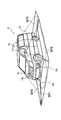
- FIG. 2 is a diagram showing an arrangement example when the cameras 1a to 1d are attached to the vehicle V.
- the cameras 1a to 1d are configured by using an image sensor such as a CCD (Charge Coupled Devices) and are installed at different positions outside the vehicle V, respectively, and take images in four directions around the vehicle.
- the camera 1a installed at a predetermined position in front of the vehicle V such as the vicinity of the front grille is an image of an object or road surface existing in the area SP1 in front of the vehicle V and in the space in front thereof. Take a picture (front view image).
- the camera 1d installed at a predetermined position on the left side of the vehicle V, such as a left side mirror, captures an image of an object or road surface (left side view image) existing in the space SP2 on the left side of the vehicle V and in the surrounding space.
- a camera 1c installed at a predetermined position behind the vehicle V, such as a roof spoiler, captures an image (rear view image) of an object or road surface that exists in the area SP3 behind the vehicle V and in the space behind it.
- the camera 1b installed at a predetermined position on the right side of the vehicle V, such as a right side mirror, displays an image of an object or road surface (right side view image) existing in the space SP4 on the right side of the vehicle V and in the surrounding space.
- the control device 10 acquires captured images captured by the cameras 1a to 1d.
- the number and positions of the cameras 1 can be determined as appropriate according to the size and shape of the vehicle V, the detection area setting method, and the like.
- the plurality of cameras 1 described above are assigned identifiers corresponding to respective addresses (arrangements), and the control device 10 can identify each camera 1 based on each identifier. Further, the control device 10 can send an activation command and other commands to the specific camera 1 by attaching an identifier.
- proximity sensors 2a to 2d are arranged in the vicinity of the cameras 1a to 1d.
- the proximity sensors 2a to 2d are ultrasonic sensors that can detect whether an object exists in a predetermined region around the vehicle V, or whether an object around the vehicle is approaching or separated from the vehicle V, infrared rays Sensors, electrostatic sensors and the like.
- the vehicle monitoring system 1000 of the present embodiment further includes a monitoring device 100, a vehicle controller 200, a communication device 400, and an external terminal device 800.
- the vehicle monitoring system 1000 can include an ignition switch 300 that can exchange information with the vehicle controller 200.
- Each of these apparatuses is connected by CAN (Controller
- CAN Controller
- the monitoring device 100 can communicate with an external terminal device 800 (computer) including a mobile phone, a smartphone, or other communication device 810 via the communication device 400.
- the external terminal device 800 includes a communication device 810, an image processing device 820, and a display 830.
- the communication device 810 acquires a captured image from the vehicle monitoring device 100 side, and the image processing device 820 displays a display mode ( Image processing necessary for display is executed according to (moving image, streaming, or still image), and the display 830 displays the captured image.
- a user who owns the external terminal device 800 can check the captured image of the vehicle transmitted from the vehicle monitoring device 100 using the external terminal device 800.
- the control device 10 of the monitoring device 100 determines the monitoring level, generates a monitoring image in a display mode according to the monitoring level, and sends it to the external terminal device 800.
- a RAM (Random Access Memory) 13 that functions as a device is provided.
- the control apparatus 10 of the monitoring apparatus 100 executes each function by cooperation of software for realizing a monitoring level determination function, a monitoring image generation function, and a transmission function, and the hardware described above. be able to.
- the control device 10 transmits each control command will be described as an example.
- the control device 10 of the present embodiment may control the camera 1 and the communication device 400 via the vehicle controller 200. Is possible.
- the monitoring device 100 receives the engine off signal input to the ignition switch 300 and the electronic key of the vehicle V having a communication function does not exist in the vicinity of the vehicle V (electronic key).
- the monitoring process can be started when the user carrying the camera is away from the vehicle V) or when a monitoring image request command is received from the external terminal device 800 of the user.
- the trigger for the monitoring process is not limited to this, and the monitoring apparatus 100 detects when an unillustrated sonar detects an object around the vehicle V, or when the door contact sensor detects an abnormality such as contact with the door.
- the anomaly sensor detects an abnormality such as vehicle tilt (getting in), or when the anomaly detection sensor detects an anomaly such as opening a door or breaking a window, an object to be monitored is detected from the captured image of the camera 1
- the monitoring process can be started when an input signal is input to a switch (not shown) of the monitoring apparatus 100.
- the monitoring device 100 includes an image processing control unit (Image Processing Unit: IPCU).
- IPCU Image Processing Unit
- the control device 10 analyzes the captured image of each camera 1 using the image processing control unit, extracts an image corresponding to the object from the captured image data, and further detects the object detected based on the amount of movement of the extracted image Whether or not is a moving object, and if it is a moving object, the amount of movement can be calculated. Further, the control device 10 can calculate a change in the position of the object over time from the change in the captured image. Based on the change in the position of the object over time, the control device 10 can detect the monitoring target object. For these image processes, a method known at the time of filing can be used.
- the control device 10 of the monitoring device 100 detects information (signal) indicating the vehicle V or a situation around the vehicle V, and this vehicle based on the detected vehicle status (information corresponding to the vehicle status). Determine the monitoring level of V.
- the control device 10 has a high possibility of danger in the vehicle when the “monitoring target object existing around the vehicle V” is detected from the captured images captured by the cameras 1a to 1d. It is conceivable that.
- the monitoring target object in the present embodiment is an object having a height and movable, such as a human being.
- the control device 10 determines that a monitoring target object has been detected when an image corresponding to an object having a predetermined height or more is detected from the captured image of the camera 1 and the position of the image changes over time. Can do.
- the above-described image processing control unit Image Processing Control Unit: ⁇ ⁇ ⁇ IPCU
- the control device 10 can detect the presence of the monitoring target object that moves by using the detection results of the proximity sensors 2a to 2d.
- control device 10 of the present embodiment analyzes the captured image captured by the camera 1 with time, and if a “monitoring target object approaching the vehicle V” is detected from the captured image, the control device 10 is dangerous to the vehicle. Is likely to occur.
- the control device 10 It can be determined whether or not the monitored object is approaching the vehicle V.
- the control device 10 may cause danger to the vehicle when “a monitoring target object staying in a region near the vehicle V for a predetermined time or longer” is detected from the captured image captured by the camera 1. Is considered high.
- the control apparatus 10 determines that the area of the image corresponding to the monitoring target object detected from the captured image is equal to or larger than the predetermined value range for a predetermined time, or the existence distance of the monitoring target object detected by the proximity sensors 2a to 2d is the predetermined time. It is possible to determine whether or not the monitoring target object is staying around the vehicle V by being less than the predetermined value.
- the control device 10 of the present embodiment acquires an abnormality occurrence signal from various vehicle state detection sensors provided in the vehicle V, it is considered that there is a high possibility that the vehicle will be in danger.
- an abnormality detection sensor included in the vehicle V a contact sensor that detects that a human body or the like has come into contact with the vehicle when the engine is off, an unlocking sensor that detects unlocking (opening) of the door when the engine is off, and a human body when the engine is off.
- a vehicle monitoring sensor known at the time of filing can be used, such as an inclination sensor that detects the inclination of the vehicle when a force is applied to the vehicle or a human body gets into the vehicle.
- control device 10 of the present embodiment does not detect the monitoring target object from the captured image of the camera 1 or moves away from the vehicle V even if the monitoring target object is detected, or generates an abnormality occurrence signal from the vehicle. If not received, it can be determined that there is no high possibility of danger in the vehicle.
- FIG. 3 is a diagram illustrating an example of a correspondence relationship between a vehicle situation and a monitoring level.
- the monitoring level is determined to be the most enhanced level 7
- the monitoring target object detected from the captured image of the camera 1 stays in the vicinity of the vehicle for a predetermined time or more, there is a high probability of causing harm to the vehicle, such as trying to open the door of the vehicle.
- the monitoring level is the next enhanced level 6. Since the monitoring level is determined to be the next enhanced level 5 and a monitoring target object is detected from the captured image of the camera 1, the suspicious person is in the vehicle. Touch Monitoring levels since situations Runado is considered it can be determined that the next level 4.
- the above level 7 to level 4 can be defined as enhancement levels at which monitoring should be enhanced. As the monitoring level increases, the numerical value indicating the enhancement level for strengthening the monitoring increases.
- the monitoring target object detected from the captured image of the camera 1 is separated from the vehicle, the monitoring target object is considered to be a passerby that passes by the vehicle.
- the level can be determined to be the next level 3. If the object detected from the captured image of the camera 1 is a stationary object, it is considered that a building or the like has been detected. If the monitoring image request command is received from the user's external terminal device 800, the monitoring level can be determined to be a lower level 1 because it is not a situation based on the situation of the vehicle.
- the above levels 3 to 1 can be defined as standard levels for which normal monitoring may be performed.
- the control device 10 of the present embodiment captures an image captured by the camera 1 in a display mode of the number of frames per unit time (hereinafter also referred to as a frame rate) obtained according to the defined (determined) monitoring level.
- a monitoring image based on the is generated.
- the frame rate in this embodiment means the number of frames per unit time.
- the unit time here can be arbitrarily set, and the unit time is not limited to 1 second.
- the control device 10 of the present embodiment When it is determined that the monitoring level is the enhanced level (for example, levels 7 to 4 shown in FIG. 3), the control device 10 of the present embodiment is installed in the vehicle according to the enhanced level.
- One of the monitoring images having a different frame rate of a moving image, streaming video, or still image based on the captured image captured by the captured camera is generated.
- the control device 10 of the present embodiment generates a monitoring image with a higher frame rate as the enhancement level is higher.
- the control device 10 of the present embodiment when the monitoring level is the standard level (default monitoring level), the control device 10 of the present embodiment generates a still image monitoring image with the lowest frame rate, and the monitoring level is higher than the standard level.
- the enhancement level a streaming video or moving image monitoring image having a frame rate higher than that of the still image is generated.
- the frame rate is the number of frames per unit time (number of images), and the unit time may be 1 second or a plurality of seconds.
- a still image has a single image captured or displayed in a unit time, and a streaming video or moving image has a plurality of images captured or displayed in a unit time.
- the number of frames (frame rate) per unit time of the moving image is larger than the number of frames (frame rate) per unit time of the streaming video. Note that the number of frames per unit time (frame rate) defined as streaming video and the number of frames per unit time (frame rate) defined as moving images can be set as appropriate.
- the monitoring when it is determined that the monitoring level is high and a monitoring image that indicates the movement of the monitoring target object around the vehicle is requested in order to enhance the monitoring, the monitoring such as a high frame rate video or streaming image can be detected. Images can be generated and provided.
- the control device 10 when it is determined that the monitoring level is the standard level (for example, levels 3 to 1 shown in FIG. 3), the control device 10 according to the present embodiment sets the standard level (monitoring level). Accordingly, it is possible to generate a monitoring image in a display mode (for example, a still image) with a low frame rate applied during normal monitoring (when the monitoring level is not strengthened). Note that the display mode applied during normal monitoring is not limited to still images.
- the control device 10 of the present embodiment sets the frame rate (fps: frame per second) to about 30, that is, a unit time (for example, 1 second). ), A monitoring image of a moving image in which 30 captured images can be continuously reproduced is generated. That is, when the monitoring level is high, it is possible to generate a moving image monitoring image with a high frame rate that makes it easy to understand the movement of the monitoring target object. Furthermore, as shown in the figure, the frame rate of the monitoring image can be lowered as the monitoring level is lowered (the degree of enhancement of monitoring is lowered). Specifically, the frame rate is about 20 when the monitoring level is level 6, the frame rate is about 10 when the monitoring level is level 5, and the frame rate is about 5 when the monitoring level is level 4. be able to.
- the frame rate in this embodiment is the number of images reproduced per unit time
- a still image can be obtained when the frame rate is 1
- a moving image can be obtained when the frame rate is about 30 to 20.
- a monitoring image can be obtained and the frame rate is about 10 to 5
- there is no smoothness as a moving image but a monitoring image of a streaming video that can show the motion of the monitoring target object by frame advance is obtained. be able to.
- the numerical value of the frame rate increases, it is possible to obtain a monitoring image that is smoother and easier to understand the movement of the monitoring target object.
- the frame rate value increases, the amount of data transmitted to the external terminal device 800 increases and the communication cost also increases.
- the control device 10 of this embodiment can generate a monitoring image at a default frame rate when the monitoring level is a standard monitoring level of 3 or less.
- a monitoring level when the monitoring level is level 3, a still image with a frame rate of 1 can be generated.
- the default frame rate is single is shown, but a plurality of values of 2 or 3 is also possible.
- a common frame rate can be applied.
- FIG. 3 is merely an example of the frame rate, and the frame rate according to the monitoring level can be arbitrarily set.
- a high frame rate video or streaming video When monitoring images can be generated, but it is only necessary to check the conditions around the vehicle with low urgency, a single frame rate can be used to generate only a static state but a small amount of monitoring images. can do. Thereby, while generating a monitoring image having a different display mode depending on the monitoring level, it is possible to reduce the amount of data by sending a still image when there is no need to track movement. As a result, the total amount of communication data when transmitting the monitoring image to the external terminal device 800 can be reduced, and the communication cost when the monitoring system is operating can be reduced.
- the control device 10 when the time when the monitoring level is detected is after sunset, the control device 10 according to the present embodiment monitors the frame rate by correcting the number of frames per unit time determined according to the monitoring level to be high. An image can be generated. Since it is generally dark after sunset, it is often difficult to obtain a clear captured image. For this reason, the control apparatus 10 of this embodiment correct
- the time of the clock provided in the control device 10 and the sunset time information corresponding to the point may be obtained by comparison, or the illuminance provided in the vehicle
- the brightness around the vehicle may be detected from the sensor, or the ambient brightness may be detected using the CCD element of the camera 1.
- control device 10 can maintain or correct the frame rate determined according to the monitoring level.
- control apparatus 10 of the present embodiment can increase the frame rate of the captured image of the camera 1 that has detected the monitoring target object from the viewpoint of obtaining a monitoring image in a display mode that can track the movement. Specifically, when the monitoring target object is included in the captured image captured by the camera 1, the control device 10 displays the corrected frame rate by correcting the frame rate obtained according to the monitoring level to be high. The monitoring image of the captured image captured by the camera 1 can be generated.
- a monitoring image that can track the movement of the monitoring target object is required. There is a case where it is not necessary to convert the monitoring image into a moving image or streaming video.
- only the display mode of the monitoring image based on any of the captured images of the cameras 1a to 1d that captured the captured image including the image corresponding to the monitoring target object is a moving image or streaming video, and the other cameras 1a to 1d are used.
- the monitoring image based on the captured image is a still image, so that the movement of the monitoring target object can be tracked, and the total data amount of the monitoring image to be finally transmitted to the external terminal device 800 can be reduced.
- the control device 10 of the present embodiment can increase the frequency of generating the monitoring image.
- the latest monitoring image is requested. Therefore, in order to meet this request, the control of this embodiment is performed.
- the apparatus 10 can generate the latest monitoring image with high frequency. If the generated monitoring image is sequentially transmitted to the external terminal device 800, the user can check the latest vehicle situation by the external terminal device 800 in real time.
- the control device 10 can transmit information including the generated monitoring image to the external terminal device 800 using the communication line 900 that can be used as a public communication network.
- the control device 10 can store the moving image as a single moving image file, and when the monitoring image is a streaming video, the control device 10 can store it in a format that can be transferred and reproduced by a streaming method.
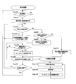
- FIG. 4 is a flowchart showing a control procedure of the vehicle monitoring system 1000 according to the present embodiment.
- step 10 the control device 10 of the monitoring device 100 according to the present embodiment determines whether it is the monitoring start timing. In the present embodiment, when the engine is OFF and the vehicle key is not nearby, the timing at which the monitoring image request command is received from the external terminal device 800 possessed by the user is recognized as the monitoring start timing, and the monitoring process is started. To do.
- the monitoring apparatus 100 acquires vehicle status information that is information indicating the status of the vehicle V or the surroundings of the vehicle V. Specifically, the monitoring device 100 acquires an abnormality occurrence signal from various vehicle state detection sensors such as a door contact sensor, a tilt sensor, and an abnormality detection sensor, and acquires a captured image of each imaging region captured by the camera 1. To do.
- step 12 if the control device 10 has acquired an abnormality occurrence signal from various vehicle state detection sensors such as a door contact sensor, a tilt sensor, and an abnormality detection sensor, the process proceeds to step 17.
- various vehicle state detection sensors such as a door contact sensor, a tilt sensor, and an abnormality detection sensor
- step 13 the control device 10 determines based on the captured image captured by the camera 1 whether there is a monitoring target object. If there is no monitoring target object, the process waits for a monitoring image request in step 16, and if the monitoring image request is not input, the processing from step 11 is continued. If a monitoring image request is accepted in step 16, the process proceeds to step 17.
- step 14 If a monitoring target object is detected in step 13, it is determined in step 14 whether the monitoring target object is approaching the vehicle. If it is determined in step 14 that an object to be monitored is detected but not approaching the vehicle, the process proceeds to step 17.
- step 15 determines whether or not the monitoring target object stays around the vehicle for a predetermined time or more. Judging.
- the monitoring target object exists and is approaching the vehicle, but has not stayed around the vehicle for a predetermined time or when the monitoring target object is present and approaches the vehicle, and further around the vehicle. In any case where the user stays for a predetermined time or longer, the process proceeds to Step 17.
- step 17 the control device 10 determines the monitoring level of the vehicle V based on the vehicle situation acquired in the process of steps 12 to 16.
- the correspondence shown in FIG. 3 can be referred to.
- step 18 the control device 10 obtains the frame rate or display mode corresponding to the monitoring level.
- the correspondence shown in FIG. 3 can be referred to.
- step 19 the control device 10 generates a monitoring image having a display mode corresponding to the calculated frame rate. The generated monitoring image is stored at least temporarily.
- step 20 the control device 10 transmits information including the generated monitoring image to the external terminal device 800, and the processing is repeated until it is determined in step 21 that the monitoring processing is finished.
- step 31 the external terminal device 800 receives the monitoring image sent from the monitoring device 100 by the communication device 810, the image processing device 820 performs necessary image processing in step 32, and the display 830 designates in step 33.
- the information including the monitoring image of the display mode is displayed.
- the monitoring method of the vehicle V can control the camera 1 and the communication device 400.
- a part of or all of the processing can be executed in a server (computer / control device) capable of exchanging information with a client (computer / control device).
- the server can be located remotely from the client.
- the monitoring device 100 and the vehicle monitoring system 1000 according to the embodiment of the present invention configured and operating as described above have the following effects.
- an image is captured by the camera 1 installed in the vehicle V in a display mode obtained based on the monitoring level determined based on the vehicle V or a vehicle situation around the vehicle V. Since the monitored image of the captured image is transmitted to the external terminal device 800, the video to be monitored can be shown in an appropriate display mode, and the surroundings of the vehicle can be compared to the case where the captured image of the camera is transmitted as it is. It is possible to reduce the total amount of monitoring image data transmitted to monitor the image. As a result, the communication cost required for vehicle monitoring can be reduced.
- the same effect as the monitoring device 100 can be obtained and the same effect can be obtained.
- the monitoring device 100 when the presence of the monitoring target object is detected from the captured image captured by the camera 1, the monitoring level of the vehicle V is determined as the enhancement level, and the normal frame rate is determined. Since the monitoring image of a moving image or streaming video with a higher frame rate is transmitted to the external terminal device 800, when enhancing the monitoring, the monitoring image of the moving image or streaming video that can track the movement of the monitoring target object by increasing the frame rate When it is not necessary to enhance the monitoring, the frame rate can be lowered to generate a monitoring image with a small data amount. As a result, the communication cost required for vehicle monitoring can be reduced.
- the monitoring apparatus 100 when a monitoring target object approaching the vehicle V is detected from the captured image captured by the camera 1, the monitoring level of the vehicle V is determined as the enhancement level, Since a monitoring image of a moving image or streaming video with a frame rate higher than the frame rate is transmitted to the external terminal device 800, when enhancing the monitoring, a moving image or streaming video capable of tracking the movement of the monitoring target object by increasing the frame rate When it is not necessary to strengthen the monitoring, the frame rate can be lowered to generate a monitoring image with a small amount of data. As a result, the communication cost required for vehicle monitoring can be reduced.
- the monitoring apparatus 100 when a monitoring target object staying in a region near the vehicle V for a predetermined time or longer is detected from a captured image captured by the camera 1, the monitoring level of the vehicle V is enhanced. Since the moving image or streaming video monitoring image having a frame rate higher than the normal frame rate is transmitted to the external terminal device 800, the frame rate is increased to increase the motion of the monitoring target object. A monitoring image of a moving image or streaming video that can be tracked is generated, and when it is not necessary to enhance the monitoring, a frame rate can be lowered to generate a monitoring image with a small amount of data. As a result, the communication cost required for vehicle monitoring can be reduced.
- the monitoring apparatus 100 when an abnormality occurrence signal is acquired from the vehicle V, the monitoring level of the vehicle V is determined as the enhancement level, and a moving image or streaming with a frame rate higher than the normal frame rate is determined. Since the monitoring image of the video is transmitted to the external terminal device 800, when enhancing the monitoring, it is necessary to increase the frame rate and generate a monitoring image of a moving image or streaming video that can track the movement of the monitoring target object, thereby enhancing the monitoring. When there is no image, it is possible to reduce the frame rate and generate a monitoring image with a small amount of data. As a result, the communication cost required for vehicle monitoring can be reduced.
- the monitoring device 100 when a request for a monitoring image is acquired from the external terminal device 800, the monitoring level of the vehicle V is determined to be the standard level, and the display mode is equal to or less than the standard frame rate. Since the monitoring image is transmitted to the external terminal device 800, when it is not necessary to strengthen the monitoring, the frame rate can be lowered to generate a monitoring image with a small data amount. As a result, the communication cost required for vehicle monitoring can be reduced.
- the monitoring device 100 when the time when the monitoring level is detected is after sunset, the monitoring image of the captured image with the frame rate corrected to be high is transmitted to the external terminal device 800. If there is a concern about insufficient exposure, the frame rate can be lowered to prevent the monitor image from becoming unclear.
- a corrected image obtained by increasing the pressure frame rate obtained in accordance with the monitoring level is applied to the captured image captured by the camera 1 that captured the captured image including the monitoring target object. Since the monitoring image of the display mode is transmitted to the external terminal device 800, only the captured image of the camera 1 that captured the captured image including the image corresponding to the monitoring target object is generated as a high frame rate moving image or streaming video, By generating the captured image as a still image with a low frame rate, it is possible to reduce the total amount of monitoring image data to be finally transmitted to the external terminal device 800.
- the frequency of generating the monitoring image can be increased, so that the monitoring that requires the latest monitoring image is required. Since the latest monitoring image can be generated frequently and transmitted to the external terminal device 800 at the time of strengthening, the user can check the latest vehicle status using the external terminal device 800.
- a monitoring device 100 according to the second embodiment and a vehicle monitoring system including the monitoring device 100 will be described.
- the configurations of the monitoring device 100 and the vehicle monitoring system 1000 of the second embodiment are basically the same as the configurations of the monitoring device 100 and the vehicle monitoring system 1000 of the first embodiment shown in FIGS.
- the description in the first embodiment is used, and the following description focuses on the different points.
- the control device 10 of the monitoring device 100 detects information (signal) indicating the vehicle V or a situation around the vehicle V, and this vehicle based on the detected vehicle status (information corresponding to the vehicle status). Determine the monitoring level of V.
- the control device 10 has a high possibility of danger in the vehicle when the “monitoring target object existing around the vehicle V” is detected from the captured images captured by the cameras 1a to 1d. It is conceivable that.
- the monitoring target object in the present embodiment is an object having a height and movable, such as a human being.
- the control device 10 determines that a monitoring target object has been detected when an image corresponding to an object having a predetermined height or more is detected from the captured image of the camera 1 and the position of the image changes over time. Can do.
- the above-described image processing control unit Image Processing Control Unit: ⁇ ⁇ ⁇ IPCU
- the control device 10 can detect the presence of the monitoring target object that moves by using the detection results of the proximity sensors 2a to 2d.
- control device 10 of the present embodiment analyzes the captured image captured by the camera 1 with time, and if a “monitoring target object approaching the vehicle V” is detected from the captured image, the control device 10 is dangerous to the vehicle. Is likely to occur.
- the control device 10 It can be determined whether or not the monitored object is approaching the vehicle V.
- the control device 10 may cause danger to the vehicle when “a monitoring target object staying in a region near the vehicle V for a predetermined time or longer” is detected from the captured image captured by the camera 1. Is considered high.
- the control apparatus 10 determines that the area of the image corresponding to the monitoring target object detected from the captured image is equal to or larger than the predetermined value range for a predetermined time, or the existence distance of the monitoring target object detected by the proximity sensors 2a to 2d is the predetermined time. It is possible to determine whether or not the monitoring target object is staying around the vehicle V by being less than the predetermined value.
- the control device 10 of the present embodiment acquires an abnormality occurrence signal from various vehicle state detection sensors provided in the vehicle V, it is considered that there is a high possibility that the vehicle will be in danger.
- an abnormality detection sensor included in the vehicle V a contact sensor that detects that a human body or the like has come into contact with the vehicle when the engine is off, an unlocking sensor that detects unlocking (opening) of the door when the engine is off, and a human body when the engine is off.
- a vehicle monitoring sensor known at the time of filing can be used, such as an inclination sensor that detects the inclination of the vehicle when a force is applied to the vehicle or a human body gets into the vehicle.
- control device 10 does not detect the monitoring target object from the captured image of the camera 1 or moves away from the vehicle V even when the monitoring target object is detected, or receives an abnormality occurrence signal from the vehicle. If not, it can be determined that there is no high possibility of danger in the vehicle.
- FIG. 5 is a diagram illustrating an example of a correspondence relationship between a vehicle situation and a monitoring level.
- the monitoring level is determined to be the most enhanced level 7
- the monitoring target object detected from the captured image of the camera 1 stays in the vicinity of the vehicle for a predetermined time or more, there is a high probability of causing harm to the vehicle, such as trying to open the door of the vehicle.
- the monitoring level is the next enhanced level 6. Since the monitoring level is determined to be the next enhanced level 5 and a monitoring target object is detected from the captured image of the camera 1, the suspicious person is in the vehicle. Touch Monitoring levels since situations Runado is considered it can be determined that the next level 4.
- the above level 7 to level 4 can be defined as enhancement levels at which monitoring should be enhanced. As the monitoring level increases, the numerical value indicating the enhancement level for strengthening the monitoring increases.
- the monitoring target object detected from the captured image of the camera 1 is separated from the vehicle, the monitoring target object is considered to be a passerby that passes by the vehicle.
- the level can be determined to be the next level 3. If the object detected from the captured image of the camera 1 is a stationary object, it is considered that a building or the like has been detected. If the monitoring image request command is received from the user's external terminal device 800, the monitoring level can be determined to be a lower level 1 because it is not a situation based on the situation of the vehicle.
- the above levels 3 to 1 can be defined as standard levels for which normal monitoring may be performed.
- the control device 10 generates a monitoring image obtained by compressing the captured image captured by the camera 1 with the data compression rate calculated according to the determined monitoring level.
- the control device 10 uses the enhancement level according to the enhancement level. It is possible to generate a monitoring image obtained by compressing the captured image of the camera 1 at a compression rate lower than the standard compression rate (default compression rate) applied when there is no image. As a result, when it is determined that the monitoring level is high and a detailed monitoring image with a high image quality is required to enhance the monitoring, a monitoring image with a low data compression rate and a high image quality can be generated and provided. .
- the standard compression rate default compression rate
- the control device 10 when it is determined that the monitoring level is a standard level (for example, levels 3 to 1 shown in FIG. 5), the control device 10 according to the present embodiment performs normal operation according to the standard level.
- a monitoring image obtained by compressing the captured image of the camera 1 at a compression rate equal to or higher than the standard compression rate (default compression rate) applied during monitoring (when the monitoring level is not strengthened) can be generated.
- the control device 10 of the present embodiment generates a monitoring image with a compression rate of 100%, that is, a captured image as it is when the monitoring level is level 7. To do. That is, when the monitoring level is high, it is possible to generate a monitoring image that does not degrade the image quality of the captured image. Furthermore, as shown in the figure, as the monitoring level decreases (the degree of monitoring enhancement decreases), the compression rate when generating the monitoring image can be increased. Specifically, when the monitoring level is level 6, the compression rate is 90%, when the monitoring level is level 5, the compression rate is 80%, and when the monitoring level is level 4, the compression rate is 70%. be able to.
- the compression rate in this embodiment is the degree of compression
- the degree of compression increases as the numerical value of the compression rate decreases.
- the control device 10 can generate a monitoring image at a compression rate equal to or lower than the default standard compression rate when the monitoring level is a standard monitoring level of 3 or lower.
- the compression rate is 60% when the monitoring level is level 3
- the compression rate is 50% when the monitoring level is level 2
- the compression rate is 40 when the monitoring level is level 1. %.
- a common standard compression rate may be applied.
- FIG. 5 is merely an example of the compression rate, and the compression rate and the standard compression rate according to the monitoring level can be arbitrarily set.
- a monitoring image by compressing a captured image at a compression rate corresponding to the monitoring level, if you want to obtain detailed information with high urgency, a high-quality monitoring image with a low compression rate.
- a monitoring image with a small data amount can be generated even if the image quality is low due to the high compression rate.
- the amount of data can be reduced by compression when detailed information is not required.
- the total amount of communication data when transmitting the monitoring image to the external terminal device 800 can be reduced, and the communication cost when the monitoring system is operating can be reduced.
- the control device 10 uses the corrected compression rate obtained by correcting the value of the compression rate obtained according to the monitoring level to be low.
- the captured image can be compressed. Since it is generally dark after sunset, it is often difficult to obtain a clear captured image. For this reason, the control apparatus 10 of this embodiment correct
- the time of the clock provided in the control device 10 and the sunset time information corresponding to the point may be obtained by comparison, or the illuminance provided in the vehicle
- the brightness around the vehicle may be detected from the sensor, or the ambient brightness may be detected using the CCD element of the camera 1.
- control device 10 can maintain or correct the compression ratio value determined according to the monitoring level.
- control device 10 of the present embodiment can reduce the compression rate of the captured image of the camera 1 that has detected the monitoring target object from the viewpoint of obtaining a detailed monitoring image. Specifically, when the monitoring target object is included in the captured image captured by the camera 1, the control device 10 uses the corrected compression rate obtained by correcting the compression rate obtained according to the monitoring level to be low. It is possible to generate a monitoring image obtained by compressing the captured image captured by the above method.
- the control device 10 of the present embodiment can increase the frequency of generating the monitoring image.
- the latest monitoring image is requested. Therefore, in order to meet this request, the control of this embodiment is performed.
- the apparatus 10 can generate the latest monitoring image with high frequency. If the generated monitoring image is sequentially transmitted to the external terminal device 800, the user can check the latest vehicle situation by the external terminal device 800 in real time.
- the control device 10 can transmit information including the generated monitoring image to the external terminal device 800 using the communication line 900 that can be used as a public communication network.
- the monitoring image may be stored as a single moving image file, or may be stored in a form that can be transferred and reproduced by a streaming method.
- FIG. 6 is a flowchart showing a control procedure of the vehicle monitoring system 1000 according to the present embodiment.
- step 10 the control device 10 of the monitoring device 100 according to the present embodiment determines whether it is the monitoring start timing. In the present embodiment, when the engine is OFF and the vehicle key is not nearby, the timing at which the monitoring image request command is received from the external terminal device 800 possessed by the user is recognized as the monitoring start timing, and the monitoring process is started. To do.
- the control device 10 acquires vehicle status information that is information indicating the status of the vehicle V or the surroundings of the vehicle V.
- the monitoring device 100 acquires an abnormality occurrence signal from various vehicle state detection sensors such as a door contact sensor, a tilt sensor, and an abnormality detection sensor, and acquires a captured image of each imaging region captured by the camera 1. To do.
- step 12 if the control device 10 has acquired an abnormality occurrence signal from various vehicle state detection sensors such as a door contact sensor, a tilt sensor, and an abnormality detection sensor, the process proceeds to step 17.
- various vehicle state detection sensors such as a door contact sensor, a tilt sensor, and an abnormality detection sensor
- step 13 the control device 10 determines based on the captured image captured by the camera 1 whether there is a monitoring target object. If there is no monitoring target object, the process waits for a monitoring image request in step 16, and if the monitoring image request is not input, the processing from step 11 is continued. If a monitoring image request is accepted in step 16, the process proceeds to step 17.
- step 14 If a monitoring target object is detected in step 13, it is determined in step 14 whether the monitoring target object is approaching the vehicle. If it is determined in step 14 that an object to be monitored is detected but not approaching the vehicle, the process proceeds to step 17.
- step 15 determines whether or not the monitoring target object stays around the vehicle for a predetermined time or more. Judging.
- the monitoring target object exists and is approaching the vehicle, but has not stayed around the vehicle for a predetermined time or when the monitoring target object is present and approaches the vehicle, and further around the vehicle. In any case where the user stays for a predetermined time or longer, the process proceeds to Step 17.
- step 17 the control device 10 determines the monitoring level of the vehicle V based on the vehicle situation acquired in the process of steps 12 to 16.
- the correspondence shown in FIG. 5 can be referred to.
- step 18 the control device 10 calculates a compression rate according to the monitoring level.
- the correspondence shown in FIG. 5 can be referred to.
- step 19 the control device 10 generates a monitoring image obtained by compressing the captured image at the calculated compression rate. The generated monitoring image is stored at least temporarily.
- step 20 the control device 10 transmits information including the generated monitoring image to the external terminal device 800, and the processing is repeated until it is determined in step 21 that the monitoring processing is finished.
- step 31 the external terminal device 800 receives the monitoring image sent from the monitoring device 100 by the communication device 810, the image processing device 820 performs necessary image processing in step 32, and the display 830 monitors in step 33. Display information including images.
- the monitoring method of the vehicle V can control the camera 1 and the communication device 400.
- a part of or all of the processing can be executed in a server (computer / control device) capable of exchanging information with a client (computer / control device).
- the server can be located remotely from the client.
- the monitoring device 100 and the vehicle monitoring system 1000 according to the embodiment of the present invention configured and operating as described above have the following effects.
- an image is captured by the camera 1 installed in the vehicle V at a compression rate calculated according to the monitoring level determined based on the vehicle V or a vehicle situation around the vehicle V. Since the monitoring image obtained by compressing the captured image is transmitted to the external terminal device 800, the total data amount of the monitoring image transmitted for monitoring the surroundings of the vehicle is reduced as compared with the case where the monitoring image is always transmitted at a constant compression rate. be able to. As a result, the communication cost required for vehicle monitoring can be reduced.
- the same effect as the monitoring device 100 can be obtained and the same effect can be obtained.
- the monitoring device 100 when the presence of the monitoring target object is detected from the captured image captured by the camera 1, the monitoring level of the vehicle V is determined as the enhancement level, and normal standard compression is performed. Since the monitoring image obtained by compressing the captured image at a compression rate lower than the rate is transmitted to the external terminal device 800, when enhancing the monitoring, it is necessary to lower the compression rate to generate a monitoring image with good image quality and to enhance the monitoring. When there is not, it is possible to generate a monitoring image with a small data amount by increasing the compression rate. As a result, the communication cost required for vehicle monitoring can be reduced.
- the monitoring apparatus 100 when a monitoring target object approaching the vehicle V is detected from the captured image captured by the camera 1, the monitoring level of the vehicle V is determined as the enhancement level, Since the monitoring image obtained by compressing the captured image at a compression rate lower than the standard compression rate is transmitted to the external terminal device 800, when the monitoring is strengthened, the compression rate is lowered to generate a monitoring image with good image quality. When it is not necessary to reinforce, a monitoring image with a small data amount can be generated by increasing the compression rate. As a result, the communication cost required for vehicle monitoring can be reduced.
- the monitoring apparatus 100 when a monitoring target object staying in a region near the vehicle V for a predetermined time or longer is detected from a captured image captured by the camera 1, the monitoring level of the vehicle V is enhanced. Since the monitoring image obtained by determining the level and compressing the captured image at a compression rate lower than the normal standard compression rate is transmitted to the external terminal device 800, when the monitoring is strengthened, the monitoring rate is improved by reducing the compression rate. When it is not necessary to enhance the monitoring, it is possible to increase the compression rate and generate a monitoring image with a small data amount. As a result, the communication cost required for vehicle monitoring can be reduced.
- the monitoring apparatus 100 when an abnormality occurrence signal is acquired from the vehicle V, the monitoring level of the vehicle V is determined to be the enhancement level, and the captured image is captured at a compression rate lower than the normal standard compression rate. Is transmitted to the external terminal device 800.
- the compression rate is reduced to generate a monitoring image with good image quality.
- the compression rate is increased. A monitoring image with a small amount of data can be generated. As a result, the communication cost required for vehicle monitoring can be reduced.
- the monitoring device 100 when a request for a monitoring image is acquired from the external terminal device 800, the monitoring level of the vehicle V is determined to be the standard level, and the compression rate is equal to or higher than the standard compression rate. Since the monitoring image obtained by compressing the captured image is transmitted to the external terminal device 800, when it is not necessary to enhance the monitoring, it is possible to generate a monitoring image with a small data amount by setting the compression rate to be equal to or higher than the standard compression rate. As a result, the communication cost required for vehicle monitoring can be reduced.
- the monitoring device 100 when the time when the monitoring level is detected is after sunset, the monitoring image obtained by compressing the captured image by correcting the compression rate is transmitted to the external terminal device 800.
- the compression ratio can be lowered to prevent the monitoring image from becoming unclear.
- the frequency of generating the monitoring image can be increased, so that the monitoring that requires the latest monitoring image is required. Since the latest monitoring image can be generated frequently and transmitted to the external terminal device 800 at the time of strengthening, the user can check the latest vehicle status using the external terminal device 800.
- the monitoring device 100 and the vehicle monitoring system 1000 will be described as an example of one aspect of the vehicle monitoring device according to the present invention, but the present invention is not limited to this.
- the vehicle monitoring apparatus having a camera, a monitoring level determination unit, a monitoring image generation unit, and a transmission unit, a camera 1, a monitoring level determination function, a monitoring image
- generation function and a transmission function is demonstrated, it is not limited to this.
- a vehicle monitoring system 1000 including the monitoring device 100 according to the present invention, a vehicle controller 200, a communication device 400, and an external terminal device 800 is provided.
- the present invention will be described by way of example, but the present invention is not limited to this.
- a crime prevention device As described above, a crime prevention device is known that, when an external stimulus detected by a door contact sensor or the like is detected, causes the camera to image the surroundings and transfers the image information to an external mobile phone or the like. However, if the captured image of the camera is transmitted as it is, there is a problem that the amount of communication data is large and the burden of communication time and communication cost is large.
- the moving object monitoring apparatus When the object to be monitored is detected, the moving object monitoring apparatus according to the present embodiment transmits a moving image generated based on a captured image including an image corresponding to the monitoring target object to the outside.
- the vehicle monitoring system 1000 transmits a moving image to an external terminal only when a monitoring target object is detected around the moving body, and is therefore transmitted to monitor the surroundings of the moving body.
- the total amount of monitoring image data can be reduced. As a result, it is possible to reduce the communication cost necessary for monitoring the mobile object.
- a third embodiment of the present invention will be described with reference to the drawings.
- a case where the vehicle monitoring apparatus according to the present invention is applied to a vehicle monitoring system 1000 for monitoring a vehicle will be described as an example.
- a case where the moving body is a vehicle will be described as an example.
- the moving object to be monitored is not limited to a vehicle, and the vehicle monitoring apparatus according to the present invention can also monitor a motorcycle, a ship, a heavy machine, a forklift, and the like.
- FIG. 7 is a block configuration diagram of a vehicle monitoring system 1000 including the monitoring device 100 according to the present embodiment.
- the vehicle monitoring system 1000 according to the present embodiment includes four cameras 1a to 1d (hereinafter sometimes collectively referred to as cameras 1) installed in the vehicle.
- FIG. 8 is a diagram showing an arrangement example when the cameras 1a to 1d are attached to the vehicle V.
- the cameras 1a to 1d are configured by using an image sensor such as a CCD (Charge Coupled Devices) and are installed at different positions outside the vehicle V, respectively, and take images in four directions around the vehicle.
- the camera 1a installed at a predetermined position in front of the vehicle V such as the vicinity of the front grille is an image of an object or road surface existing in the area SP1 in front of the vehicle V and in the space in front of the area. (Hereinafter referred to as a front view image).
- the camera 1d installed at a predetermined position on the left side of the vehicle V such as a left side mirror is an image of an object or road surface existing in the space SP2 on the left side of the vehicle V and in the surrounding space (hereinafter referred to as a left side view image).
- a camera 1c installed at a predetermined position behind the vehicle V such as a roof spoiler shoots an image of an object or road surface (hereinafter referred to as a rear view image) existing in the area SP3 behind the vehicle V and in the space behind the vehicle SP. .
- the camera 1b installed at a predetermined position on the right side of the vehicle V, such as a right side mirror, is an image of an object or road surface existing in the space SP4 on the right side of the vehicle V and in the surrounding space (hereinafter, a right side view image).
- the control device 10 acquires captured images captured by the cameras 1a to 1d.
- the number and positions of the cameras 1 can be determined as appropriate according to the size and shape of the vehicle V, the detection area setting method, and the like.
- the plurality of cameras 1 described above are assigned identifiers corresponding to respective addresses (arrangements), and the control device 10 can identify each camera 1 based on each identifier. Further, the control device 10 can send an activation command and other commands to the specific camera 1 by attaching an identifier.
- proximity sensors 2a to 2d can be disposed in the vicinity of the cameras 1a to 1d.
- the proximity sensors 2a to 2d are ultrasonic sensors that can detect whether an object exists in a predetermined region around the vehicle V, or whether an object around the vehicle is approaching or separated from the vehicle V, infrared rays Sensors, electrostatic sensors and the like.
- the vehicle monitoring system 1000 of the present embodiment further includes a monitoring device 100, a vehicle controller 200, a communication device 400, and an external terminal device 800.
- the vehicle monitoring system 1000 can include an ignition switch 300 that can exchange information with the vehicle controller 200.
- Each of these apparatuses is connected by CAN (Controller
- CAN Controller
- the monitoring device 100 can communicate with an external terminal device 800 (computer) including a mobile phone, a smartphone, or other communication device 810 via the communication device 400.
- the external terminal device 800 acquires monitoring information including a monitoring image from the monitoring device 100 via the communication device 810.
- the external terminal device 800 also includes an image processing device 820 that generates a display image based on the acquired monitoring image, and a display 830 that displays the generated display image.
- a user having the external terminal device 800 can view the vehicle monitoring image transmitted from the monitoring device 100 on the display 830 of the external terminal device 800.
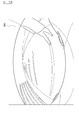
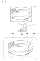
- FIG. 9 is a diagram showing a display example of the monitoring image Q ′ for display on the external terminal device 800.
- the display monitoring image Q ′ shown in FIG. 9 includes a monitoring image R1 based on a captured image of the camera 1a, a monitoring image R2 based on a captured image of the camera 1b, a monitoring image R3 based on a captured image of the camera 1c, and a camera. It includes a monitoring image R4 based on the 1d captured image and a virtual vehicle model image R0 when the vehicle V is viewed from above.
- the monitoring images R1 to R4 may be moving images that continuously show state changes, or may be still images that show temporary states.
- monitoring images R1 to R4 it is also possible to display a part of the monitoring images R1 to R4 as a moving image and the other as a still image. With such a monitoring image Q, the user can monitor the state around the vehicle V even when the user is in a place separated from the vehicle V.
- the control device 10 of the monitoring device 100 stores a ROM (Read Only Memory) in which a program for generating a monitoring image and sending it to an external terminal device is stored. 12 and a CPU (Central Processing Unit) 11 as an operation circuit that functions as the monitoring device 100 and a RAM (Random Access Memory) 13 that functions as an accessible storage device by executing a program stored in the ROM 12. And.
- ROM Read Only Memory
- CPU Central Processing Unit
- RAM Random Access Memory
- the control device 10 of the monitoring device 100 can execute each function by the cooperation of software for realizing the monitoring image generation function and the transmission function and the hardware described above.
- the control device 10 transmits each control command will be described as an example.
- the control device 10 of the present embodiment may control the camera 1 and the communication device 400 via the vehicle controller 200. Is possible.
- the monitoring device 100 receives the engine off signal input to the ignition switch 300 and the electronic key of the vehicle V having a communication function does not exist in the vicinity of the vehicle V (electronic key).
- the monitoring process can be started when a request to request a monitoring image is received from the terminal device 800 of the user.
- the trigger of the monitoring process is not limited to this, and the monitoring device 100 detects the inclination sensor when the sonar (not shown) detects an object around the vehicle V, when the door contact sensor detects contact with the door.
- the abnormality detection sensor detects an abnormality such as opening the door or breaking a window, or when a moving body such as a vehicle is detected from the captured image of the camera 1,
- the monitoring process can be started when an input signal is input to a switch (not shown) of the monitoring apparatus 100.
- the monitoring apparatus 100 includes an image processing control unit (Image Processing Unit: IPCU).
- IPCU Image Processing Unit
- the control device 10 analyzes the captured image of each camera 1 using the image processing control unit, extracts an image corresponding to the object from the captured image data, and further moves the object based on the amount of movement of the extracted image. The amount can be calculated. Further, the control device 10 can calculate the change in the position of the object over time from the change in the captured image. Based on the change in the position of the object over time, the control device 10 can determine whether or not an object existing around the vehicle V is a monitoring target object to be monitored.
- IPCU Image Processing Unit
- the control device 10 detects the object as a monitoring target object, and after the detection, the captured image including the monitoring target object Can be stored in the image memory in the control device 10 together with the time information.
- a method known at the time of filing can be used.
- the control device 10 of the monitoring device 100 uses the above-described image processing control unit (Image Processing Control Unit: IPCU) to capture the surroundings of a moving body such as a vehicle from images captured by the cameras 1a to 1d. If the presence of the monitoring target object is detected and the presence of the monitoring target object is detected, based on the captured image including the image corresponding to the monitoring target object, A moving image that continuously indicates a change in state is generated as a monitoring image.
- the moving image in the present embodiment is image information in which a plurality of images are sequentially displayed within a unit time, and can indicate a change in the state of the monitoring area.
- the control device 10 associates a plurality of captured images captured at a predetermined time T with the monitoring timing (imaging timing) after the monitoring target object is detected.
- the monitoring device 100 compresses and stores a monitoring image of a moving image as necessary.
- the monitoring image may be stored as a single moving image file, or may be stored in a form that can be transferred and reproduced by a streaming method.
- the monitoring apparatus 100 when the moving speed (movement amount per unit time) of the monitoring target object calculated based on the captured image is smaller than a predetermined value, the monitoring apparatus 100 according to the third embodiment performs unit time of the moving image.
- a monitoring image is generated by reducing the frame rate, which is the number of images included in the area. That is, when the moving speed of the monitoring target object is low, the frame rate is reduced according to the movement.
- the amount of movement of the monitoring target object is small, it is possible to reduce the amount of moving image data to be transmitted at the time of monitoring without sending a moving image with an excessive frame rate.
- a moving image with a relatively high frame rate is sent according to the speed of the movement, and a monitoring image showing the movement of the monitoring target object in detail is sent. Can be generated.
- control device 10 of the monitoring device 100 when no monitoring target object is detected around a moving body such as a vehicle, is a still image indicating a temporary state around the moving body such as a vehicle. As a monitoring image.
- the control device 10 can compress and store the generated still image monitoring image as necessary.
- FIG. 10 is a flowchart showing a control procedure of the vehicle monitoring system 1000 according to the third embodiment.
- the control device 10 of the monitoring device 100 determines whether it is the monitoring start timing.
- the timing at which the monitoring image request command is received from the terminal device 800 possessed by the user is recognized as the monitoring start timing, and the monitoring process is started.
- the monitoring start timing is not limited, and the monitoring process can be started at a timing when the contact sensor of the vehicle door, the inclination sensor, the vehicle abnormality detection sensor, etc. detect the abnormality.
- step 20 the monitoring apparatus 100 causes the cameras 1a to 1d to start imaging each imaging region, and acquires captured images.
- the monitoring apparatus 100 determines whether or not the captured image acquired from the camera 1 is the first one.
- the process proceeds to step 40, where the first captured image is stored as the reference monitoring image G0, and is transmitted to the external terminal device 800 to be the next captured image. Wait.
- the reference monitoring image G0 is a captured image acquired at a reference monitoring timing t0 that serves as a reference when the surroundings of the vehicle V are monitored.
- the first captured image is the reference monitoring image G0.
- the present invention is not limited to this, and the captured image at the reference monitoring timing t0 that satisfies a predetermined condition can be defined as the reference monitoring image G0.
- the process proceeds to step 50, and the monitoring apparatus 100 determines whether or not a monitoring target object exists based on the change amount of the image data of the captured image. To do.
- the currently acquired captured image may be compared with the reference monitored image G0, or the currently acquired monitored image may be compared with the previously acquired captured image. Good.
- the process proceeds to step 60, where the monitoring apparatus 100 continuously shows a change in state around the vehicle V based on a captured image including an image corresponding to the monitoring target object.
- a monitoring image That is, the monitoring image represented by the moving image includes an image of the monitoring target object.
- the monitoring apparatus 100 can identify the cameras 1a to 1d that have captured images in which the presence of the monitoring target object is detected, and can generate monitoring images based on the captured images of the cameras 1a to 1d.
- step 61 the monitoring apparatus 100 calculates the moving speed of the monitoring target object based on the captured image. If the moving speed of the monitoring target object is less than a predetermined value, the monitoring apparatus 100 proceeds to step 62.
- the frame rate of the monitoring image of the moving image is reduced.
- the monitoring apparatus 100 defines in advance a relationship in which the frame rate decreases as the moving speed of the monitoring target object decreases, and obtains the frame rate based on the moving speed of the monitoring target object with reference to this relationship. it can.
- the process proceeds to step 80 without changing the frame rate.
- step 50 when the monitoring target object is not detected in step 50, the process proceeds to step 70, and a still image indicating a temporary state around the vehicle V is generated as a monitoring image.
- step 80 the generated moving image or still image monitoring image is sent to the external terminal device 800. Thereafter, the process proceeds to step 90 and waits for the end timing of the monitoring process (timing that the electronic key possessed by the occupant approaches the communicable distance, the occupant turns on the engine, etc.). When the process ends, the process returns to step 10 to wait for the next monitoring start timing, and when it does not end, the process returns to step 30 to wait for the acquisition of the next captured image.
- the external terminal device 800 is a computer having members corresponding to a CPU, a RAM, and a ROM, and includes a communication device 810, an image processing device 820, and a display 830.
- the communication device 810 receives the monitoring image (step 110) and sends the received monitoring image to the image processing device 820.
- the image processing apparatus 820 includes an image processing control unit (Image Processing Control Unit: IPCU), and can perform image processing on the received monitoring image (step 120).
- the received monitoring image is assigned an identifier that identifies the camera 1 that captured the image, and the image processing apparatus 820 can assign each monitoring image to each display area according to the identifier.
- the image processing device 820 allocates each pixel of the received monitoring image to each pixel in the display area of the display 830, and displays the monitoring images R1 to R4 shown in FIG.
- a monitoring image of a moving image is transmitted to an external terminal only when a monitoring target object is detected around the host vehicle V.
- the total amount of monitoring image data transmitted to monitor the surroundings of the vehicle V can be reduced. As a result, it is possible to reduce communication costs necessary for monitoring vehicles and other moving objects.
- the monitoring device 100 and the vehicle monitoring system 1000 when a monitoring target object is not detected, a still image with a small amount of data is transmitted, so that it is at a position separated from the vehicle.
- the user can check a temporary state around the vehicle with a still image. For this reason, the surroundings of the vehicle can be monitored by the image while suppressing the amount of transmission data of the monitoring image.
- the frame rate is set according to the moving speed of the monitoring target object.
- the monitoring image with a small data amount can be created while capturing the movement (state change) of the monitoring target object, and the transmission data amount in the monitoring process can be reduced.
- a monitoring device 100 and a vehicle monitoring system 1000 according to a fourth embodiment of the present invention will be described with reference to FIGS.
- the monitoring device 100 and the vehicle monitoring system 1000 of the fourth embodiment are different from those of the third embodiment in the method of creating a monitoring image and the monitoring image to be created, but the configuration shown in FIG. 7 and the basic control shown in FIG. The procedure is common.
- the following description will focus on different points, and the description of the third embodiment will be cited for other points.
- FIG. 11 is a flowchart showing a control procedure of the monitoring device 100 and the vehicle monitoring system 1000 according to the fourth embodiment of the present invention.
- the monitoring device 100 executes the same processing as the control procedure of the third embodiment shown in FIG. 10 and transmits the reference monitoring image G0 to the external terminal device 800 as in Step 40.
- the external terminal device 800 receives the reference monitoring image G0 (step 210) and stores the received reference monitoring image G0 (step 220).
- FIG. 12A is a diagram illustrating an example of the reference monitoring image G0.
- the monitoring device 100 starts generating a monitoring image when the monitoring timing tK is reached.
- the monitoring timing tK is one or a plurality of timings after the reference monitoring timing t0 (imaging timing of the reference monitoring image G0) serving as a reference when monitoring the surroundings of the vehicle V.
- the monitoring timing tK may be a timing that circulates in a predetermined cycle, or may be a timing that satisfies a predetermined condition such as when a monitoring command input from the user's external terminal device 800 is received.
- step 120 the monitoring device 100 acquires a comparison image captured by the camera 1 at the monitoring timing tK.
- FIG. 12B is a diagram illustrating an example of the contrast image GK. Compared to the reference monitoring image G0 in FIG. 12A, an image corresponding to the object appears on the right side of the comparison image GK.
- the monitoring apparatus 100 compares the reference monitoring image G0 imaged at the reference monitoring timing t0 with the contrast image captured at one or more monitoring timings after the reference monitoring timing t0, A difference image corresponding to a change in image data of the image is obtained. Since the background image does not change while the vehicle is parked or stopped, such as when the engine is stopped, when the difference between the reference monitoring image G0 and the comparison image GK is taken, a difference image ⁇ G whose image has changed from the reference monitoring image G0 is extracted at the monitoring timing tK. be able to.
- FIG. 13 is a diagram illustrating an example of the difference image ⁇ G.
- the white frame including the region where the image data is changed is defined as the difference image ⁇ G.
- the entire image shown in FIG. 13 is defined as the difference image ⁇ G
- the difference image ⁇ G is defined in the region other than the region of the difference image ⁇ G. An identifier indicating that it is not can be attached.
- the monitoring apparatus 100 obtains the coordinates (xk, yk) of the vertex P of the difference image ⁇ G that can define the position with respect to the contrast image GK. Since the contrast image GK and the reference monitoring image G0 are defined by common coordinates, the position of the difference image ⁇ G with respect to the reference monitoring image G0 can be obtained from the coordinates (xk, yk).
- the monitoring device 100 transmits a monitoring image Q based on the difference image ⁇ G to the external terminal device 800.
- the monitoring image Q is transmitted at a timing later than the transmission timing of the reference monitoring image G0.
- the position information P (xk, yk) of the difference image ⁇ G may be included in the monitoring image. it can.
- FIG. 15 is a diagram illustrating an example of a monitoring image to be transmitted.
- the monitoring image Q transmitted by the monitoring device 100 is image data corresponding to the difference image ⁇ G, and thus the monitoring image transmitted in the third embodiment (corresponding to FIG. 12B). ) Can significantly reduce the amount of data.
- the monitoring apparatus 100 may obtain a monitoring image in which the first identifier is attached to the image data of the invariable region other than the region corresponding to the difference image ⁇ G in the comparison image GK acquired at the monitoring timing. It can.
- the first identifier is information for identifying an invariable region in the comparison image GK that has the same image data as the reference monitoring image G0. That is, the invariant region to which the first identifier is attached can be handled as a background portion that has not changed from the reference monitoring image G0 described above, and the image data of the reference monitoring image G0 transmitted earlier can be used.
- step 230 the external terminal device 800 receives the monitoring image to which each information is attached.
- FIG. 16 is a diagram for explaining a monitoring image generation method at the monitoring timing tK.
- the external terminal device 800 reads the reference monitoring image G0 received and stored in the previous step 220, superimposes the difference image ⁇ G received in step 230 on the reference monitoring image G0, and at the monitoring timing tK.
- a monitoring image Q′K for display is created. Note that the reference monitoring image G0 shown in FIG. 16 is common to the reference monitoring image G0 shown in FIG. 12A, and the difference image ⁇ G shown in FIG.
- the difference image ⁇ G is pasted to the corresponding position of the reference monitoring image G0 based on the address.
- the position information P (xk, yk) of the difference image ⁇ G shown in FIG. 14 is acquired, and the difference image ⁇ G is obtained at the corresponding position of the reference monitoring image G0. Can be pasted.
- the lower diagram in FIG. 16 shows an example in which the created monitor image Q′K for display is displayed on the display 830.
- the monitoring image Q′K in which the difference image ⁇ G is superimposed on the reference monitoring image G0 is substantially the same (substantially equivalent) image information as the comparison image GK shown in FIG. 12B captured at the monitoring timing tK. It is.
- the same operational effects as the third embodiment can be obtained, and at a certain monitoring timing tK, the reference monitoring image G0 can be compared. Since only the difference image ⁇ G is transmitted to the external terminal device 800, the total amount of monitoring image data transmitted to monitor the surroundings of the vehicle V can be reduced. As a result, the communication cost required for monitoring the vehicle V can be reduced.
- the vehicle monitoring system 1000 of the present embodiment when the monitoring image Q at a certain monitoring timing tK is generated, only the difference image ⁇ G corresponding to the changed area changed compared to the reference monitoring image G0 is newly added. Since the previously transmitted reference monitoring image G0 is used for the portion corresponding to the invariable region that has been transmitted or received and has not changed compared to the reference monitoring image G0, the comparison image GK at the monitoring timing tK is transmitted as it is. It is possible to reduce the image quality of the monitoring image Q ′ to be displayed while reducing the transmission data amount as compared with the case. As a result, the user can monitor the vehicle V with a clear monitoring image Q ′ while saving communication costs.
- a monitoring device 100 and a vehicle monitoring system 1000 according to a fifth embodiment of the present invention will be described with reference to FIGS.
- the monitoring device 100 and the vehicle monitoring system 1000 of the fifth embodiment are different from those of the third and fourth embodiments in the method of creating a monitoring image and the monitoring image to be created, but the configuration shown in FIG. 7 and the basics shown in FIG.
- the common control procedure is common.
- the following description will focus on different points, and the description of the third and fourth embodiments will be cited for other points.
- FIG. 17 is a flowchart showing a control procedure of the monitoring device 100 and the vehicle monitoring system 1000 according to the fifth embodiment of the present invention.
- the monitoring device 100 executes the same processing as the control procedure of the third embodiment shown in FIG. 10 and transmits the reference monitoring image G0 to the external terminal device 800 as in Step 40.
- the external terminal device 800 receives the reference monitoring image G0 (step 410) and stores the received reference monitoring image G0 (step 420).
- the monitoring device 100 starts generating the monitoring image of this example when it is the monitoring timing tK.
- This monitoring timing tK is an arbitrary continuous plurality of timings that come around in a predetermined cycle after a certain reference monitoring timing t0 (imaging timing of the reference monitoring image G0) as a reference for monitoring the surroundings of the vehicle V. .
- a certain reference monitoring timing t0 imaging timing of the reference monitoring image G0
- the monitoring timing t (K-1) follows after the reference monitoring timing t0, followed by the monitoring timing tK.
- the monitoring timing t (K ⁇ 1) is the monitoring timing immediately before the monitoring timing tK.
- a plurality of monitoring timings t (1) to t (K-2) are set between the reference monitoring timing t0 and the monitoring timing t (K-1), and the imaging process is performed by the camera 1 at each monitoring timing.
- the monitoring apparatus 100 stores these monitoring images.
- the reference monitoring image G0 of FIG. 18 is common to the reference monitoring image G0 shown in FIG. 12A, and the Kth comparison image GK of FIG. 18 is common to the comparison image GK at the monitoring timing tK shown in FIG. 12B.
- step 320 the monitoring apparatus 100 according to the present embodiment compares the Kth contrast image GK captured at the Kth monitoring timing after the reference monitoring timing t0 (K is a natural number, the same applies hereinafter) with the reference monitoring image G0.
- K is a natural number, the same applies hereinafter
- FIG. 18 shows the Kth difference image ⁇ G (0 ⁇ K).
- the monitoring apparatus 100 detects the Kth contrast image GK captured at the Kth monitoring timing tK after the reference monitoring timing t0, and the (K-1) timing immediately before the Kth monitoring timing tK.
- the (K-1) th difference image ⁇ G (-1) of both images is extracted by comparing with the (K-1) th contrast image G (K-1) imaged at t (K-1).
- FIG. 18 shows the (K ⁇ 1) th difference image ⁇ G ( ⁇ 1).
- the monitoring apparatus 100 divides the Kth difference image ⁇ G (0-K) into three regions, and assigns an identifier to each. Specifically, among the (1) K-th difference image ⁇ G (0 ⁇ K), a first identifier is assigned to image data in an invariable region that is not different from the reference monitoring image G0, and (2) the K-difference image ⁇ G (0 -K), the second identifier is assigned to the image data of the overlapping change area included in the (K-1) -th contrast image, and (3) of the K-th difference image ⁇ G (0-K), K-1) A third identifier is assigned to the image data of the most recently changed area included only in the difference image ⁇ G ( ⁇ 1).
- the monitoring apparatus 100 uses the Kth difference image ⁇ G (0 ⁇ K) and the (K) as the latest change regions included only in the (K ⁇ 1) th difference image ⁇ G ( ⁇ 1).
- -1) A logical product (overlapping region) with the difference image ⁇ G ( ⁇ 1) or the (K ⁇ 1) th difference image ⁇ G ( ⁇ 1) is assigned a third identifier, and the Kth difference image ⁇ G (0 ⁇ K) ) In white and black in the (K ⁇ 1) th difference image ⁇ G ( ⁇ 1), that is, the (K ⁇ 1) th difference image ⁇ G ( ⁇ 1) from the Kth difference image ⁇ G (0 ⁇ K).
- the subtracted region can be given a second identifier, and the first identifier can be given to the remaining region to which the second identifier and the third identifier are not attached.
- the method for attaching the identifier is not particularly limited.
- the image of the region to which the second identifier is attached appears in the comparison image GK, but also appears in the comparison image G (K-1) at the monitoring timing tK-1. Therefore, when monitoring the surroundings of the vehicle V, the pixel value of the comparison image G (K ⁇ 1) at the monitoring timing tK ⁇ 1 can be used as the monitoring image as it is for the image of the region to which the second identifier is attached. it can.
- the image of the region to which the first identifier is attached is an invariable region that does not change at the monitoring timing tK when the reference monitoring timing t0 is used as a reference.
- the background image does not change.
- the pixel value of the reference monitoring image G0 at the reference monitoring timing t0 can be used as it is as the monitoring image for the image of the region to which the first identifier is attached.
- each identifier can be color information.
- 0 (zero: black value) color information is attached to the pixel to which the first identifier using the reference monitoring image G0 is attached
- the (K ⁇ 1) th contrast image G (K ⁇ 1 (white value) color information is attached to a pixel attached with the second identifier using 1)
- 0.5 (gray) is attached to a pixel attached with the third identifier using the K-th contrast image GK.
- Value color information
- FIG. 18 shows a replacement image H in which black, white, and gray color information is attached to the Kth differential image ⁇ G (0-K) as the first to third identifiers.
- the monitoring apparatus 100 corresponds the image data of the image area to which the third identifier (gray value) of the Kth difference image ⁇ G (0-K) is assigned to the image area.
- FIG. 18 shows a Kth monitoring image QK in which the image of the Kth contrast image GK is pasted in the region of the third identifier (gray value) of the replacement image H.
- the image of the region to which the third identifier is attached is an image corresponding to the state change from the monitoring timing tK-1 to tK, it appears only in the contrast image GK imaged at the monitoring timing tK. ing. For this reason, when monitoring the periphery of the vehicle V, the pixel value of the comparison image GK at the monitoring timing tK can be used as it is as the monitoring image for the image of the region assigned with the third identifier.
- the monitoring apparatus 100 includes the information of the first and second identifiers, and the area with the third identifier (gray value) is replaced with the image data of the Kth contrast image GK.
- Information including the monitoring image QK and the coordinates (xk, yk) of the vertex P specifying the position of the Kth monitoring image QK is sent to the external terminal device 800.
- the process described below is a process related to the Kth monitoring timing tK, but as shown in step 430, the first to the first (K-1) monitoring timings created before that are the first to the (K-1) monitoring timings. (K-1)
- the monitoring image is stored on the external terminal device 800 side.
- step 440 shown in FIG. 17 the external terminal device 800 displays the Kth monitoring image QK including the image data of the Kth contrast image GK corresponding to the region to which the third identifier is attached, the first identifier, and the second identifier. Receive.
- the external terminal device 800 reads the reference monitoring image G 0 stored in step 420 and the display-use (K ⁇ 1) monitoring image Q ′ (K ⁇ 1) generated in step 430.
- the (K-1) th monitoring image Q '(K-1) includes the reference monitoring image G0, the (K-2) th monitoring image Q' (K-2), and the (K-1) th monitoring image Q '(K). -1), it can be obtained by the same process as the process for generating the Kth monitoring image QK described above.
- step 460 the external terminal device 800 generates a monitoring image QK at the monitoring timing tK based on the reference monitoring image G0, the (K-1) th monitoring image Q (K-1), and the Kth monitoring image QK. .
- FIG. 19 is a diagram for explaining a method of generating a monitoring image Q′K for display at the monitoring timing tK according to the processing in step 460.
- the external terminal device 800 reads the reference monitoring image G0 received and stored in the previous step 420, and the (K-1) th monitoring created and stored for display in the previous step 430 as well. Read the image Q (K-1).
- the external terminal device 800 replaces the image data of the image area to which the first identifier is assigned in the Kth monitoring image QK received in step 440 with the image data of the reference monitoring image G0, and attaches the second identifier.
- the image data of the image area thus formed is replaced with the image data of the (K-1) th monitoring image Q (K-1) to create a Kth monitoring image QK for display.
- the image data of the K-th contrast image GK is already attached to the image data of the pixel region to which the third identifier is attached.
- the reference monitoring image G0 shown in FIG. 19 is common to the reference monitoring image G0 shown in FIG. 18, and the (K-1) monitoring image Q (K-1) shown in FIG. K-1) Almost the same as the contrast image G (K-1) (substantially equivalent).
- the image data of the Kth monitoring image QK is pasted to the corresponding position of the reference monitoring image G0 based on the address.
- the position information P (xk, yk) of the Kth monitoring image QK shown in FIG. 18 is acquired and the corresponding position of the reference monitoring image G0 is obtained.
- the image data of the Kth monitoring image QK (image data of the Kth contrast image GK) can be pasted.
- the diagram on the right side of FIG. 19 shows an example in which a monitor image Q′K for display at the monitor timing tK is displayed on the display 830.
- each identifier of the Kth monitoring image QK is replaced with the image data of the reference monitoring image G0 and the image data of the (K-1) th monitoring image Q (K-1) for display.
- the monitoring image Q′K is image information substantially common (substantially equivalent) to the Kth contrast image GK shown in FIG. 18 captured at the monitoring timing tK.
- the monitoring device 100 and the vehicle monitoring system 1000 according to the fifth embodiment of the present invention configured and operating as described above have the same effects as the third embodiment and the following effects.
- the reference monitoring image G0 transmitted earlier and the display at the (K-1) monitoring timing generated earlier on the external terminal device 800 side.
- the Kth contrast image GK at a certain monitoring timing tK and the immediately previous (K-1) contrast image G K- Since the image data of the Kth contrast image GK only needs to be transmitted for the difference from 1), the total amount of monitoring image data transmitted to monitor the surroundings of the vehicle V can be reduced. As a result, the communication cost required for monitoring the vehicle V can be reduced.
- the identifier is used to designate the pixel area using the reference monitoring image G0 or the (K-1) th monitoring image Q (K-1), so that it is transmitted to monitor the surroundings of the vehicle V.
- the total amount of monitoring image data can be reduced.
- the data compression rate can be increased, so that the total data amount of the monitoring image to be transmitted can be further reduced.
- the vehicle monitoring system 1000 of the present embodiment when generating the monitoring image Q at a certain monitoring timing tK, only the difference image from the immediately preceding (K-1) contrast image G (K-1). For the portion corresponding to the invariable area that has not changed compared to the reference monitoring image G0, the previously transmitted reference monitoring image G0 is used as the immediately preceding (K-1) contrast image G. Since the previously created (K-1) monitoring image Q (K-1) is used for the portion corresponding to the maintenance area that has not changed compared to (K-1), the comparison at the monitoring timing tK is made.
- the transmission data amount can be reduced, and the image quality of the displayed monitoring image Q ′ can be prevented from being deteriorated.
- the user can monitor the vehicle V with the clear monitoring image Q ′ while saving the communication cost required for remote monitoring of the vehicle V.
- the monitoring device 100 and the vehicle monitoring system 1000 will be described as an example of one aspect of the vehicle monitoring device according to the present invention, but the present invention is not limited to this.
- the monitoring device 100 will be described as an aspect of the vehicle monitoring device according to the present invention having a camera, a monitoring image generation unit, and a transmission unit.
- the present invention is not limited to this.
- a vehicle monitoring system 1000 including the monitoring device 100 according to the present invention, a vehicle controller 200, a communication device 400, and an external terminal device 800 is provided.
- the present invention will be described by way of example, but the present invention is not limited to this.
Abstract
Priority Applications (4)
| Application Number | Priority Date | Filing Date | Title |
|---|---|---|---|
| US14/119,324 US9842261B2 (en) | 2011-05-24 | 2012-04-17 | Vehicle monitoring device and method of monitoring vehicle |
| CN201280024310.6A CN103548340B (zh) | 2011-05-24 | 2012-04-17 | 车辆用监视装置以及车辆的监视方法 |
| EP12789798.1A EP2717571B1 (fr) | 2011-05-24 | 2012-04-17 | Dispositif de surveillance de véhicule et procédé de surveillance de véhicule |
| JP2013516250A JP5561433B2 (ja) | 2011-05-24 | 2012-04-17 | 車両用監視装置及び車両の監視方法 |
Applications Claiming Priority (6)
| Application Number | Priority Date | Filing Date | Title |
|---|---|---|---|
| JP2011-115428 | 2011-05-24 | ||
| JP2011115428 | 2011-05-24 | ||
| JP2011-139136 | 2011-06-23 | ||
| JP2011139136 | 2011-06-23 | ||
| JP2011-139062 | 2011-06-23 | ||
| JP2011139062 | 2011-06-23 |
Publications (1)
| Publication Number | Publication Date |
|---|---|
| WO2012160902A1 true WO2012160902A1 (fr) | 2012-11-29 |
Family
ID=47216987
Family Applications (1)
| Application Number | Title | Priority Date | Filing Date |
|---|---|---|---|
| PCT/JP2012/060303 WO2012160902A1 (fr) | 2011-05-24 | 2012-04-17 | Dispositif de surveillance de véhicule et procédé de surveillance de véhicule |
Country Status (5)
| Country | Link |
|---|---|
| US (1) | US9842261B2 (fr) |
| EP (1) | EP2717571B1 (fr) |
| JP (1) | JP5561433B2 (fr) |
| CN (1) | CN103548340B (fr) |
| WO (1) | WO2012160902A1 (fr) |
Cited By (8)
| Publication number | Priority date | Publication date | Assignee | Title |
|---|---|---|---|---|
| JP2014138398A (ja) * | 2013-01-18 | 2014-07-28 | Sumitomo Electric Ind Ltd | 監視装置 |
| JP2015070350A (ja) * | 2013-09-27 | 2015-04-13 | 日産自動車株式会社 | 監視画像提示システム |
| JP2015167349A (ja) * | 2014-02-14 | 2015-09-24 | キヤノンマーケティングジャパン株式会社 | 情報処理装置、情報処理システム、その制御方法及びプログラム |
| JP2017039333A (ja) * | 2015-08-17 | 2017-02-23 | 株式会社デンソー | 車両用防犯システム、車両用防犯方法 |
| JP2017118223A (ja) * | 2015-12-22 | 2017-06-29 | 株式会社デンソー | 車両用表示装置 |
| WO2020031924A1 (fr) * | 2018-08-10 | 2020-02-13 | ソニーセミコンダクタソリューションズ株式会社 | Dispositif de traitement d'informations, dispositif terminal, procédé de traitement d'informations et programme de traitement d'informations |
| EP4090016A2 (fr) | 2021-05-12 | 2022-11-16 | Yokogawa Electric Corporation | Appareil, procédé et programme |
| WO2023053444A1 (fr) * | 2021-10-01 | 2023-04-06 | 日本電気株式会社 | Système de commande de corps mobile, procédé de commande de corps mobile et dispositif de communication d'image |
Families Citing this family (27)
| Publication number | Priority date | Publication date | Assignee | Title |
|---|---|---|---|---|
| US9141863B2 (en) * | 2008-07-21 | 2015-09-22 | Facefirst, Llc | Managed biometric-based notification system and method |
| US9405968B2 (en) * | 2008-07-21 | 2016-08-02 | Facefirst, Inc | Managed notification system |
| US9065955B2 (en) * | 2012-10-15 | 2015-06-23 | Fuji Xerox Co., Ltd. | Power supply control apparatus, image processing apparatus, non-transitory computer readable medium, and power supply control method |
| WO2014155922A1 (fr) * | 2013-03-29 | 2014-10-02 | 日本電気株式会社 | Dispositif d'identification d'objet cible, procédé d'identification d'objet cible et programme d'identification d'objet cible |
| JP5958459B2 (ja) * | 2013-12-26 | 2016-08-02 | トヨタ自動車株式会社 | 状態判定システム、状態判定方法及び移動ロボット |
| US9509960B2 (en) * | 2014-05-08 | 2016-11-29 | Verizon Patent And Licensing Inc. | Vehicle anomaly detection and reporting |
| CN104052971B (zh) * | 2014-06-26 | 2018-02-27 | 广州世荣电子有限公司 | 一种监控摄像头的自动屏蔽系统的控制方法 |
| WO2016132251A1 (fr) * | 2015-02-16 | 2016-08-25 | Coolbox S.R.L. | Dispositif et procédé permettant de surveiller un véhicule, en particulier pour la gestion d'événements de perte |
| US20160309062A1 (en) * | 2015-04-15 | 2016-10-20 | Appbanc, Llc | Metrology carousel device for high precision measurements |
| JP6775285B2 (ja) * | 2015-09-24 | 2020-10-28 | アルパイン株式会社 | 後側方車両検知警報装置 |
| CN105338317A (zh) * | 2015-10-29 | 2016-02-17 | 中国邮政集团公司广州市分公司 | 一种用于信报箱的监控方法与监控装置 |
| CN106571046B (zh) * | 2016-11-11 | 2021-07-16 | 上海市政工程设计研究总院(集团)有限公司 | 基于路面网格体系的车路协同辅助驾驶方法 |
| CN108093209B (zh) * | 2016-11-21 | 2024-04-12 | 松下知识产权经营株式会社 | 影像传输系统以及移动摄像机设备 |
| CN106696891B (zh) * | 2016-12-08 | 2019-03-12 | 奇瑞汽车股份有限公司 | 汽车防盗系统及其控制方法 |
| CN106851053A (zh) * | 2017-02-06 | 2017-06-13 | 徐文波 | 一种基于互联网的导播方法、终端和系统 |
| JP6635075B2 (ja) * | 2017-03-09 | 2020-01-22 | トヨタ自動車株式会社 | 画像記録システム、画像記録方法、画像記録プログラム |
| JPWO2019065546A1 (ja) | 2017-09-29 | 2020-10-22 | パナソニック インテレクチュアル プロパティ コーポレーション オブ アメリカPanasonic Intellectual Property Corporation of America | 三次元データ作成方法、クライアント装置及びサーバ |
| CN107945461A (zh) * | 2017-10-31 | 2018-04-20 | 上海船舶运输科学研究所 | 一种化工事故救援车的安全检测报警系统 |
| JP7006302B2 (ja) * | 2018-01-23 | 2022-01-24 | 株式会社リコー | 画像処理装置、画像処理システム、及びビデオ会議システム |
| JP6828719B2 (ja) * | 2018-06-27 | 2021-02-10 | トヨタ自動車株式会社 | 車載装置および制御方法 |
| JP7151449B2 (ja) * | 2018-12-14 | 2022-10-12 | トヨタ自動車株式会社 | 情報処理システム、プログラム、及び情報処理方法 |
| TWI700645B (zh) * | 2019-01-14 | 2020-08-01 | 中興保全科技股份有限公司 | 電子巡邏裝置 |
| CN114208161A (zh) * | 2019-08-02 | 2022-03-18 | 日产自动车株式会社 | 图像处理装置和图像处理方法 |
| US11155237B2 (en) * | 2019-08-06 | 2021-10-26 | John Leedy | Perimeter alert defense system |
| CN112802329B (zh) * | 2020-12-14 | 2022-02-01 | 国汽(北京)智能网联汽车研究院有限公司 | 一种数据展示方法、装置、设备及计算机存储介质 |
| CN112572418A (zh) * | 2020-12-15 | 2021-03-30 | 北京百度网讯科技有限公司 | 一种无人驾驶车辆的控制方法、装置及电子设备 |
| CN113099415A (zh) * | 2021-04-21 | 2021-07-09 | 深圳市车百路科技有限公司 | 一种基于北斗卫星定位、5g通信技术的车辆安全监控系统 |
Citations (6)
| Publication number | Priority date | Publication date | Assignee | Title |
|---|---|---|---|---|
| JPH11334536A (ja) * | 1998-05-29 | 1999-12-07 | Tokai Rika Co Ltd | 車両接近物体の検知装置 |
| JP2003127835A (ja) * | 2001-10-22 | 2003-05-08 | Mega Chips Corp | 車両セキュリティ装置 |
| JP2005065238A (ja) * | 2003-07-25 | 2005-03-10 | Hitachi Ltd | 監視情報提供装置および監視情報提供方法 |
| JP2005073218A (ja) * | 2003-08-07 | 2005-03-17 | Matsushita Electric Ind Co Ltd | 画像処理装置 |
| JP2006041770A (ja) * | 2004-07-26 | 2006-02-09 | Mitsubishi Heavy Ind Ltd | 画像配信方法、画像表示方法及びそれらを用いた広域監視方法と画像配信装置、画像表示装置及びそれらを用いた広域監視システム |
| JP2006107279A (ja) | 2004-10-07 | 2006-04-20 | Matsushita Electric Ind Co Ltd | 防犯装置および遠隔監視システム |
Family Cites Families (21)
| Publication number | Priority date | Publication date | Assignee | Title |
|---|---|---|---|---|
| GB2375208B (en) * | 2001-05-05 | 2004-12-22 | Land Rover Group Ltd | Vehicle security system |
| US7602413B2 (en) * | 2002-10-18 | 2009-10-13 | Sony Corporation | Information processing system and method, information processing apparatus, image-capturing device and method, recording medium, and program |
| CN1291602C (zh) * | 2003-07-25 | 2006-12-20 | 株式会社日立制作所 | 监视信息提供装置及监视信息提供方法 |
| JP2005057508A (ja) * | 2003-08-05 | 2005-03-03 | Matsushita Electric Ind Co Ltd | 動き検出装置および方法、輝度信号/色信号分離装置および方法、ノイズ低減装置および方法、映像表示装置および方法 |
| EP1671293A4 (fr) * | 2003-10-09 | 2009-04-22 | Moreton Bay Corp Pty Ltd | Systeme et procede de surveillance video |
| JP3972891B2 (ja) * | 2003-11-06 | 2007-09-05 | 株式会社デンソー | 車両監視システム |
| JP4432628B2 (ja) * | 2004-06-07 | 2010-03-17 | 株式会社デンソー | 車両遠隔監視システム、車両情報通信装置、通信端末、及び操作機 |
| JP4844795B2 (ja) * | 2004-11-02 | 2011-12-28 | 株式会社デンソー | 車両用画像撮影装置 |
| EP1806786A1 (fr) * | 2005-02-09 | 2007-07-11 | Matsushita Electric Industrial Co., Ltd. | Dispositif de camera de surveillance, systeme de surveillance utilisant ledit dispositif, et procede de transmission d'image de surveillance |
| US7302323B2 (en) * | 2005-06-01 | 2007-11-27 | Polar Industries, Inc. | Transportation data recording system |
| WO2008035745A1 (fr) * | 2006-09-20 | 2008-03-27 | Panasonic Corporation | Systeme moniteur, camera et procede de codage d'images video |
| US20080204556A1 (en) * | 2007-02-23 | 2008-08-28 | De Miranda Federico Thoth Jorg | Vehicle camera security system |
| GB2451485A (en) * | 2007-08-01 | 2009-02-04 | Airmax Group Plc | Vehicle monitoring system |
| JP5114177B2 (ja) * | 2007-12-12 | 2013-01-09 | 富士通テン株式会社 | 情報記録装置 |
| WO2009122760A1 (fr) * | 2008-04-04 | 2009-10-08 | 富士フイルム株式会社 | Dispositif de traitement d'images, procédé de traitement d'images, et support lisible par ordinateur |
| US20100245583A1 (en) * | 2009-03-25 | 2010-09-30 | Syclipse Technologies, Inc. | Apparatus for remote surveillance and applications therefor |
| US20100246669A1 (en) * | 2009-03-25 | 2010-09-30 | Syclipse Technologies, Inc. | System and method for bandwidth optimization in data transmission using a surveillance device |
| CA2712576C (fr) * | 2009-08-11 | 2012-04-10 | Certusview Technologies, Llc | Systemes et methodes applicables au traitement d'evenements complexes d'information relative a des vehicules |
| BR112012003060A2 (pt) * | 2009-08-12 | 2016-08-02 | Tech Resources Pty Ltd | uma estação base |
| US8625973B2 (en) * | 2009-10-30 | 2014-01-07 | Verint Systems, Inc. | Method and apparatus for operating a video system |
| US8836784B2 (en) * | 2010-10-27 | 2014-09-16 | Intellectual Ventures Fund 83 Llc | Automotive imaging system for recording exception events |
-
2012
- 2012-04-17 CN CN201280024310.6A patent/CN103548340B/zh active Active
- 2012-04-17 WO PCT/JP2012/060303 patent/WO2012160902A1/fr active Application Filing
- 2012-04-17 US US14/119,324 patent/US9842261B2/en active Active
- 2012-04-17 JP JP2013516250A patent/JP5561433B2/ja active Active
- 2012-04-17 EP EP12789798.1A patent/EP2717571B1/fr active Active
Patent Citations (6)
| Publication number | Priority date | Publication date | Assignee | Title |
|---|---|---|---|---|
| JPH11334536A (ja) * | 1998-05-29 | 1999-12-07 | Tokai Rika Co Ltd | 車両接近物体の検知装置 |
| JP2003127835A (ja) * | 2001-10-22 | 2003-05-08 | Mega Chips Corp | 車両セキュリティ装置 |
| JP2005065238A (ja) * | 2003-07-25 | 2005-03-10 | Hitachi Ltd | 監視情報提供装置および監視情報提供方法 |
| JP2005073218A (ja) * | 2003-08-07 | 2005-03-17 | Matsushita Electric Ind Co Ltd | 画像処理装置 |
| JP2006041770A (ja) * | 2004-07-26 | 2006-02-09 | Mitsubishi Heavy Ind Ltd | 画像配信方法、画像表示方法及びそれらを用いた広域監視方法と画像配信装置、画像表示装置及びそれらを用いた広域監視システム |
| JP2006107279A (ja) | 2004-10-07 | 2006-04-20 | Matsushita Electric Ind Co Ltd | 防犯装置および遠隔監視システム |
Cited By (10)
| Publication number | Priority date | Publication date | Assignee | Title |
|---|---|---|---|---|
| JP2014138398A (ja) * | 2013-01-18 | 2014-07-28 | Sumitomo Electric Ind Ltd | 監視装置 |
| JP2015070350A (ja) * | 2013-09-27 | 2015-04-13 | 日産自動車株式会社 | 監視画像提示システム |
| JP2015167349A (ja) * | 2014-02-14 | 2015-09-24 | キヤノンマーケティングジャパン株式会社 | 情報処理装置、情報処理システム、その制御方法及びプログラム |
| JP2017039333A (ja) * | 2015-08-17 | 2017-02-23 | 株式会社デンソー | 車両用防犯システム、車両用防犯方法 |
| JP2017118223A (ja) * | 2015-12-22 | 2017-06-29 | 株式会社デンソー | 車両用表示装置 |
| WO2020031924A1 (fr) * | 2018-08-10 | 2020-02-13 | ソニーセミコンダクタソリューションズ株式会社 | Dispositif de traitement d'informations, dispositif terminal, procédé de traitement d'informations et programme de traitement d'informations |
| US20210297839A1 (en) * | 2018-08-10 | 2021-09-23 | Sony Semiconductor Solutions Corporation | Information processing device, terminal device, information processing method, and information processing program |
| JP7444777B2 (ja) | 2018-08-10 | 2024-03-06 | ソニーセミコンダクタソリューションズ株式会社 | 情報処理装置、端末装置、情報処理方法および情報処理プログラム |
| EP4090016A2 (fr) | 2021-05-12 | 2022-11-16 | Yokogawa Electric Corporation | Appareil, procédé et programme |
| WO2023053444A1 (fr) * | 2021-10-01 | 2023-04-06 | 日本電気株式会社 | Système de commande de corps mobile, procédé de commande de corps mobile et dispositif de communication d'image |
Also Published As
| Publication number | Publication date |
|---|---|
| CN103548340A (zh) | 2014-01-29 |
| US9842261B2 (en) | 2017-12-12 |
| US20140085477A1 (en) | 2014-03-27 |
| JP5561433B2 (ja) | 2014-07-30 |
| EP2717571A1 (fr) | 2014-04-09 |
| JPWO2012160902A1 (ja) | 2014-07-31 |
| EP2717571B1 (fr) | 2018-09-05 |
| EP2717571A4 (fr) | 2015-03-04 |
| CN103548340B (zh) | 2017-12-29 |
Similar Documents
| Publication | Publication Date | Title |
|---|---|---|
| JP5561433B2 (ja) | 車両用監視装置及び車両の監視方法 | |
| EP2733937A1 (fr) | Dispositif de surveillance de véhicule, système de surveillance de véhicule, dispositif de terminal et procédé de surveillance de véhicule | |
| CN110933275B (zh) | 拍照方法及相关设备 | |
| CN102387344B (zh) | 成像装置、成像系统和成像方法 | |
| US20190199898A1 (en) | Image capturing apparatus, image processing apparatus, control method, and storage medium | |
| KR101561626B1 (ko) | 주행차량의 번호판 인식이 실시간으로 가능한 차량용 블랙박스 | |
| WO2016051981A1 (fr) | Dispositif de reconnaissance d'image embarqué sur un véhicule | |
| WO2017134982A1 (fr) | Dispositif d'imagerie | |
| US7898590B2 (en) | Device having imaging function | |
| KR20140033803A (ko) | 카메라 공차 보정 방법 및 장치와 이를 이용한 어라운드 뷰 모니터링 시스템 | |
| WO2016056088A1 (fr) | Dispositif de commande de caméra à bord d'un véhicule | |
| CN104796580B (zh) | 一种基于选择集成的实时稳像视频巡检系统 | |
| JP2016197795A (ja) | 撮像装置 | |
| JP6065629B2 (ja) | 物体検知装置 | |
| JP5872171B2 (ja) | カメラシステム | |
| WO2017169614A1 (fr) | Dispositif de traitement d'image | |
| JP2019029750A (ja) | 撮像装置 | |
| US20170364765A1 (en) | Image processing apparatus, image processing system, vehicle, imaging apparatus and image processing method | |
| JP5861279B2 (ja) | 車両用監視装置及び車両の監視方法 | |
| JP4797441B2 (ja) | 車両用画像処理装置 | |
| JP2020150295A (ja) | 車両防犯装置 | |
| JP4508043B2 (ja) | 映像監視装置及び映像監視用プログラム | |
| JP6563694B2 (ja) | 画像処理装置、画像処理システム、画像合成装置、画像処理方法及びプログラム | |
| TWI448976B (zh) | 超廣角影像處理方法與其系統 | |
| JP2011065280A (ja) | 画像処理装置、周辺監視システム、及び操作支援システム |
Legal Events
| Date | Code | Title | Description |
|---|---|---|---|
| 121 | Ep: the epo has been informed by wipo that ep was designated in this application |
Ref document number: 12789798 Country of ref document: EP Kind code of ref document: A1 |
|
| ENP | Entry into the national phase |
Ref document number: 2013516250 Country of ref document: JP Kind code of ref document: A |
|
| WWE | Wipo information: entry into national phase |
Ref document number: 2012789798 Country of ref document: EP |
|
| WWE | Wipo information: entry into national phase |
Ref document number: 14119324 Country of ref document: US |
|
| NENP | Non-entry into the national phase |
Ref country code: DE |