WO2012147557A1 - 回転機構、産業用ロボットおよび回転体の原点位置復帰方法 - Google Patents
回転機構、産業用ロボットおよび回転体の原点位置復帰方法 Download PDFInfo
- Publication number
- WO2012147557A1 WO2012147557A1 PCT/JP2012/060306 JP2012060306W WO2012147557A1 WO 2012147557 A1 WO2012147557 A1 WO 2012147557A1 JP 2012060306 W JP2012060306 W JP 2012060306W WO 2012147557 A1 WO2012147557 A1 WO 2012147557A1
- Authority
- WO
- WIPO (PCT)
- Prior art keywords
- arm
- rotating body
- detection unit
- rotating
- rotation
- Prior art date
- Legal status (The legal status is an assumption and is not a legal conclusion. Google has not performed a legal analysis and makes no representation as to the accuracy of the status listed.)
- Ceased
Links
Images



Classifications
-
- B—PERFORMING OPERATIONS; TRANSPORTING
- B25—HAND TOOLS; PORTABLE POWER-DRIVEN TOOLS; MANIPULATORS
- B25J—MANIPULATORS; CHAMBERS PROVIDED WITH MANIPULATION DEVICES
- B25J9/00—Program-controlled manipulators
- B25J9/16—Program controls
- B25J9/1656—Program controls characterised by programming, planning systems for manipulators
- B25J9/1669—Program controls characterised by programming, planning systems for manipulators characterised by special application, e.g. multi-arm co-operation, assembly, grasping
-
- B—PERFORMING OPERATIONS; TRANSPORTING
- B25—HAND TOOLS; PORTABLE POWER-DRIVEN TOOLS; MANIPULATORS
- B25J—MANIPULATORS; CHAMBERS PROVIDED WITH MANIPULATION DEVICES
- B25J9/00—Program-controlled manipulators
- B25J9/02—Program-controlled manipulators characterised by movement of the arms, e.g. cartesian coordinate type
- B25J9/04—Program-controlled manipulators characterised by movement of the arms, e.g. cartesian coordinate type by rotating at least one arm, excluding the head movement itself, e.g. cylindrical coordinate type or polar coordinate type
- B25J9/041—Cylindrical coordinate type
- B25J9/042—Cylindrical coordinate type comprising an articulated arm
-
- B—PERFORMING OPERATIONS; TRANSPORTING
- B25—HAND TOOLS; PORTABLE POWER-DRIVEN TOOLS; MANIPULATORS
- B25J—MANIPULATORS; CHAMBERS PROVIDED WITH MANIPULATION DEVICES
- B25J19/00—Accessories fitted to manipulators, e.g. for monitoring, for viewing; Safety devices combined with or specially adapted for use in connection with manipulators
- B25J19/02—Sensing devices
-
- B—PERFORMING OPERATIONS; TRANSPORTING
- B25—HAND TOOLS; PORTABLE POWER-DRIVEN TOOLS; MANIPULATORS
- B25J—MANIPULATORS; CHAMBERS PROVIDED WITH MANIPULATION DEVICES
- B25J18/00—Arms
-
- B—PERFORMING OPERATIONS; TRANSPORTING
- B25—HAND TOOLS; PORTABLE POWER-DRIVEN TOOLS; MANIPULATORS
- B25J—MANIPULATORS; CHAMBERS PROVIDED WITH MANIPULATION DEVICES
- B25J9/00—Program-controlled manipulators
- B25J9/10—Program-controlled manipulators characterised by positioning means for manipulator elements
-
- B—PERFORMING OPERATIONS; TRANSPORTING
- B25—HAND TOOLS; PORTABLE POWER-DRIVEN TOOLS; MANIPULATORS
- B25J—MANIPULATORS; CHAMBERS PROVIDED WITH MANIPULATION DEVICES
- B25J9/00—Program-controlled manipulators
- B25J9/10—Program-controlled manipulators characterised by positioning means for manipulator elements
- B25J9/1005—Program-controlled manipulators characterised by positioning means for manipulator elements comprising adjusting means
- B25J9/101—Program-controlled manipulators characterised by positioning means for manipulator elements comprising adjusting means using limit-switches, -stops
-
- B—PERFORMING OPERATIONS; TRANSPORTING
- B25—HAND TOOLS; PORTABLE POWER-DRIVEN TOOLS; MANIPULATORS
- B25J—MANIPULATORS; CHAMBERS PROVIDED WITH MANIPULATION DEVICES
- B25J9/00—Program-controlled manipulators
- B25J9/16—Program controls
- B25J9/1679—Program controls characterised by the tasks executed
- B25J9/1692—Calibration of manipulator
-
- G—PHYSICS
- G05—CONTROLLING; REGULATING
- G05B—CONTROL OR REGULATING SYSTEMS IN GENERAL; FUNCTIONAL ELEMENTS OF SUCH SYSTEMS; MONITORING OR TESTING ARRANGEMENTS FOR SUCH SYSTEMS OR ELEMENTS
- G05B2219/00—Program-control systems
- G05B2219/30—Nc systems
- G05B2219/37—Measurements
- G05B2219/37124—Magnetic sensor
-
- G—PHYSICS
- G05—CONTROLLING; REGULATING
- G05B—CONTROL OR REGULATING SYSTEMS IN GENERAL; FUNCTIONAL ELEMENTS OF SUCH SYSTEMS; MONITORING OR TESTING ARRANGEMENTS FOR SUCH SYSTEMS OR ELEMENTS
- G05B2219/00—Program-control systems
- G05B2219/30—Nc systems
- G05B2219/50—Machine tool, machine tool null till machine tool work handling
- G05B2219/50042—Return to origin, reference point, zero point, homing
-
- Y—GENERAL TAGGING OF NEW TECHNOLOGICAL DEVELOPMENTS; GENERAL TAGGING OF CROSS-SECTIONAL TECHNOLOGIES SPANNING OVER SEVERAL SECTIONS OF THE IPC; TECHNICAL SUBJECTS COVERED BY FORMER USPC CROSS-REFERENCE ART COLLECTIONS [XRACs] AND DIGESTS
- Y10—TECHNICAL SUBJECTS COVERED BY FORMER USPC
- Y10T—TECHNICAL SUBJECTS COVERED BY FORMER US CLASSIFICATION
- Y10T74/00—Machine element or mechanism
- Y10T74/20—Control lever and linkage systems
- Y10T74/20207—Multiple controlling elements for single controlled element
- Y10T74/20305—Robotic arm
- Y10T74/20317—Robotic arm including electric motor
Definitions
- the present invention relates to a rotating mechanism including a rotating body that can rotate 360 ° or more and less than 720 ° with respect to a support.
- the present invention also relates to an industrial robot provided with such a rotation mechanism.
- the present invention relates to a method for returning the origin position of a rotating body that returns a rotating body that can rotate 360 ° or more and less than 720 ° to the origin position with respect to a support.
- an industrial robot that includes an arm member, a rotation shaft that is rotatably supported by the arm member at 360 ° or more and less than 720 °, and a drive motor that rotates the rotation shaft. 1).
- the industrial robot described in Patent Document 1 includes a detection piece fixed to a rotating shaft and an origin sensor fixed to an arm member.
- the detection piece is detected by the origin sensor when the rotation axis is at the origin position.
- the rotation axis rotates 360 ° or more and less than 720 °, two rotation ranges of the rotation axis are provided.
- the detection piece is detected by the origin sensor. Therefore, in this industrial robot, it is impossible to detect that the rotation axis is at the origin position only with the detection piece and the origin sensor.
- the industrial robot described in Patent Document 1 includes an oscillating body that is swingably held by an arm member, and an attitude sensor that detects the position of the oscillating body. I have. Since the oscillating body oscillates as the rotating shaft rotates, this industrial robot detects that the rotating shaft is at the origin position based on the detection result of the attitude sensor and the detection result of the origin sensor. Yes. That is, in this industrial robot, even if the detection piece is detected by the origin sensor when the attitude sensor is off, the rotating body is not at the origin position and is detected by the origin sensor when the attitude sensor is on. If a piece is detected, it is detected that the rotation axis is at the origin position.
- Patent Document 1 does not disclose a method of returning a rotation axis that rotates 360 ° or more and less than 720 ° with respect to the arm member to the origin position.
- an object of the present invention is to reliably return the rotator to the origin position in a short time regardless of the position of the origin position of the rotator that can rotate 360 ° or more and less than 720 ° with respect to the support.
- An object of the present invention is to provide a rotating mechanism that can perform the above-described operation.
- the subject of this invention is providing the industrial robot provided with this rotation mechanism.
- an object of the present invention is to reliably return the rotating body to the original position in a short time regardless of the position of the origin of the rotating body that can rotate 360 ° or more and less than 720 ° with respect to the support.
- An object of the present invention is to provide a method of returning the origin position of a rotating body that can be performed.
- a rotating mechanism of the present invention includes a support, a rotating body that can rotate 360 ° or more and less than 720 ° with respect to the support, a motor that rotates the rotating body, and an origin of the rotating body.
- the first detection unit includes a first detection unit and a first detection unit that is fixed to either the support body or the rotating body and detects the first detection unit, and the second detection mechanism is a rocker that is swingably attached to the support body.
- the moving member fixed to or formed on the rotating body, and fixed to or formed on one of the engaging member that engages with the swinging member to swing the swinging member, and the swinging member or the support.
- the second detected part and the swinging member or support A second detection unit that is fixed to the other side and detects the second detection unit, so that the first detection unit is detected by the first detection unit at one or two positions in the rotation range of the rotating body.
- the first detection unit and the first detection unit are arranged, and the swinging member is attached to the support so that the second detection unit is turned on and off at one place in the rotation range of the rotating body, and the motor control means Is characterized in that, when the rotating body is returned to the origin position, first, the motor is controlled so that the rotating body rotates to a position where the on / off of the second detection unit is switched.
- the swinging member is attached to the support so that the second detector is turned on and off at one position in the rotating range of the rotating body, and the motor control means returns the rotating body to the origin position.
- the motor is controlled so that the rotating body rotates to a position where the on / off of the second detection unit is switched. Therefore, it is possible to reliably return the rotator to the origin position by performing a certain operation with reference to one position in the rotation range of the rotator where the on / off of the second detection unit is switched. Therefore, first, the rotating body is rotated until the first detecting unit is detected by the first detecting unit, and then the on / off state of the second detecting unit is checked to return the rotating body to the origin position.
- the present invention it is possible to reliably return the rotator to the origin position in a short time regardless of the position of the origin position of the rotator.
- the motor control means is within a range in which the first detection unit is detected by the first detection unit in a predetermined first rotation direction after the rotating body rotates to a position where the on / off of the second detection unit is switched.
- the rotating body rotates in the second rotation direction, which is the reverse direction of the first rotation direction, until the first detection unit is no longer detected by the first detection unit, and then the first detection unit It is preferable to return the rotating body to the origin position by controlling the motor so that the rotating body rotates in the first rotation direction until the detection unit detects the first detected part.
- the rotating body can be appropriately returned to the origin position. That is, when the first detection unit is the position where the first detection unit is detected and the boundary position where the on / off of the second detection unit is switched is the origin position of the rotating body, the second detection unit, Due to the product accuracy and mounting accuracy of the second detected portion and the swing member, there is a rotation mechanism that turns on the second detection portion when the rotating body is at the origin position, or the second detection portion There may be a case where there is a rotating mechanism that is turned off.
- the rotating body returns to the origin position. If the rotating body is returned to the origin position, there may be a situation where the rotating body cannot be properly returned to the origin position. With this configuration, the second detector is turned on / off. The rotating body can be returned to the origin position without using. Therefore, even if the boundary position where the first detection unit is detected by the first detection unit and the on / off state of the second detection unit is switched is the origin position of the rotation body, the rotation body is moved to the origin position. It becomes possible to return appropriately.
- the second detection mechanism is fixed to or formed on the support, and contacts the swing member to restrict the swing range on one side of the swing member.
- a second restricting member that is fixed or formed and abuts on the swing member to restrict the swing range on the other side of the swing member, and the engaging member abuts on the first restricting member.
- the swing member is swung between the first restricting position and the second restricting position at which the swing member is in contact with the second restricting member, and the second detection mechanism is configured by the second detected portion and the second detecting portion. , Detecting whether the swing member is in the first restriction position or the second restriction position.
- the second detection mechanism includes a first magnetic holding mechanism that holds the swing member at the first restriction position by a magnetic attraction force or a magnetic repulsion force, and a swing at the second restriction position by the magnetic attraction force or the magnetic repulsion force. It is preferable to include a second magnetic holding mechanism that holds the moving member. If comprised in this way, it will become possible to prevent the rocking
- the engaging member can contact the swinging member so as to press the swinging member at the first restricting position against the first restricting member, and the swinging member at the second restricting position is the second. It is preferable to be able to contact the swinging member so as to be pressed against the regulating member. If comprised in this way, the rotation range of a rotary body can be controlled using a rocking
- the rotation mechanism of the present invention can be used for industrial robots.
- the industrial robot includes a main body, a first arm whose base end is rotatably attached to the main body, and a first support serving as a support whose base end is rotatably attached to the distal end of the first arm.
- 2 arms a third arm as a rotating body whose base end side is rotatably attached to the distal end side of the second arm, and a hand whose end side is rotatably attached to the distal end side of the third arm.
- the third arm can be returned to the original position in a short time regardless of the position of the third arm that can rotate 360 ° or more and less than 720 ° relative to the second arm. Is possible.
- the origin position return method of the rotator of the present invention includes a support, a rotator capable of rotating 360 ° or more and less than 720 ° with respect to the support, and an origin position of the rotator.
- a first detection mechanism and a second detection mechanism wherein the first detection mechanism is fixed to or formed on either the support or the rotating body, and the support or the rotation.
- a first detection unit that is fixed to either one of the bodies and detects the first detected portion, and the second detection mechanism is a swing member that is swingably attached to the support body, and is fixed or formed on the rotating body.
- an engagement member that engages with the swing member to swing the swing member, a second detected portion that is fixed or formed on either the swing member or the support, and the swing member Or it is fixed to either one of the supports and detects the second detected part.
- the first detection unit and the first detection unit so that the first detection unit is detected by the first detection unit at one or two positions in the rotation range of the rotating body.
- a first rotation step is executed in which the rotating body is rotated to a position where the on / off of the second detection unit is switched.
- the origin position return method of the rotator when the rotator is returned to the origin position, first, a first rotation step is performed in which the rotator is rotated to a position where the on / off of the second detector is switched. Therefore, it is possible to reliably return the rotator to the origin position by performing a certain operation with reference to one position in the rotation range of the rotator where the on / off of the second detection unit is switched. Therefore, first, the rotating body is rotated until the first detecting unit is detected by the first detecting unit, and then the on / off state of the second detecting unit is checked to return the rotating body to the origin position.
- the present invention it is possible to reliably return the rotator to the origin position in a short time regardless of the position of the origin position of the rotator.
- the method for returning the origin position of the rotating body is a method of rotating the rotating body in a predetermined first rotation direction and within a range where the first detection unit is detected by the first detection unit after the first rotation step.
- a fourth rotation step of rotating the rotating body in the first rotation direction until the first detection unit detects the first detected portion is provided after the third rotation step.
- the rotating body can be returned to the origin position without using the on / off state of the second detection unit.
- the first detection unit is the position where the first detection unit is detected.
- the rotator can be appropriately returned to the origin position. Further, with this configuration, when the rotating body is once rotated in the second rotating direction in the third rotating step and then returned to the origin position in the fourth rotating step, for example, the rotating body is used. By reducing the rotation speed of the rotating body, it is possible to return the rotating body to the origin position with high accuracy.
- the origin of the rotating body that can rotate 360 ° or more and less than 720 ° with respect to the support is set to the origin position reliably in a short time regardless of the position of the origin. It becomes possible to return to.
- the third arm can be surely brought into the origin in a short time regardless of the origin position of the third arm which can be rotated 360 ° or more and less than 720 ° relative to the second arm. It becomes possible to return to the position.
- the rotating body can be moved in a short time regardless of the position of the origin of the rotating body that can be rotated 360 ° or more and less than 720 ° with respect to the support. It is possible to reliably return to the home position.
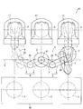
- FIG. 1 is a schematic side view of an industrial robot according to an embodiment of the present invention.
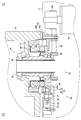
- FIG. 2 is a schematic plan view of a semiconductor manufacturing system in which the industrial robot shown in FIG. 1 is used. It is a longitudinal cross-sectional view for demonstrating the structure of the 3rd arm drive mechanism shown in FIG.
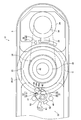
- FIG. 4 is a diagram for explaining the configuration of a third arm drive mechanism from the EE direction in FIG. 3. It is a figure for demonstrating operation
- FIG. 1 is a schematic side view of an industrial robot 1 according to an embodiment of the present invention.
- FIG. 2 is a schematic plan view of a semiconductor manufacturing system 16 in which the industrial robot 1 shown in FIG. 1 is used.
- the industrial robot 1 in this embodiment is an articulated robot for transporting a semiconductor wafer 2 (see FIG. 2).
- the industrial robot 1 includes a main body 3, a first arm 4 that is rotatably attached to the main body 3, and a second arm 5 that is rotatably attached to the first arm 4. And a third arm 6 that is rotatably attached to the second arm 5 and hands 7 and 8 that are rotatably attached to the third arm 6.
- the industrial robot 1 is referred to as “robot 1”
- the semiconductor wafer 2 is referred to as “wafer 2”.
- the robot 1 rotates the first arm 4 and the second arm 5 to expand and contract the arm portion 9 composed of the first arm 4 and the second arm 5, and the third arm 6.
- a third arm drive mechanism 12 that rotationally drives, a hand drive mechanism 13 that rotationally drives the hand 7, and a hand drive mechanism 14 that rotationally drives the hand 8 are provided.
- the robot 1 is used by being incorporated into a semiconductor manufacturing system 16, for example. Specifically, the robot 1 is arranged at the entrance of the semiconductor manufacturing system 16, takes out the wafer 2 stored in the cassette 17, and stores the wafer 2 in the processing apparatus 18.
- the main body 3 is formed in a cylindrical shape.
- An elevating mechanism (not shown) for elevating the first arm 4 is accommodated in the main body 3.
- the first arm 4, the second arm 5, and the third arm 6 are formed in a hollow shape.
- the base end side of the first arm 4 is rotatably attached to the main body 3.
- the proximal end side of the second arm 5 is rotatably attached to the distal end side of the first arm 4.
- the proximal end side of the third arm 6 is rotatably attached to the distal end side of the second arm 5.
- the main body 3, the first arm 4, the second arm 5, and the third arm 6 are arranged in this order from the lower side in the up-down direction.
- the hand 7 is formed so that the shape when viewed from above and below is substantially Y-shaped, and the wafer 2 is mounted on the tip of the bifurcated hand 7. .
- the hand 8 is formed in the same shape as the hand 7, and the wafer 2 is mounted on the tip of the hand 8 having a bifurcated shape.
- the proximal ends of the hands 7 and 8 are rotatably attached to the distal end side of the third arm 6.
- the hands 7 and 8 are arranged so as to overlap in the vertical direction. Further, the hands 7 and 8 are arranged above the third arm 6.
- the hand 7 and the hand 8 may overlap in the vertical direction, but in most cases, the hand 7 and the hand 8 do not overlap in the vertical direction.
- the rotation angle of the hand 8 relative to the hand 7 is, for example, 120 ° to 150 °.
- the arm drive mechanism 11 includes a first drive motor 20 serving as a drive source, a first speed reducer 21 for decelerating and transmitting the power of the first drive motor 20 to the first arm 4, and a first drive.
- a second speed reducer 22 for decelerating and transmitting the power of the motor 20 to the second arm 5, and a pulley and a belt (not shown) for connecting the first speed reducer 21 and the second speed reducer 22.
- the first reduction gear 21 is, for example, a harmonic drive (registered trademark) that is a wave gear device, and configures a first joint portion that connects the main body portion 3 and the first arm 4.
- the second speed reducer 22 is, for example, a harmonic drive (registered trademark), and constitutes a second joint portion that connects the first arm 4 and the second arm 5.
- the third arm drive mechanism 12 includes a second drive motor 24 serving as a drive source, and a third reducer 25 for decelerating and transmitting the power of the second drive motor 24 to the third arm 6. Yes.
- the detailed configuration of the third arm drive mechanism 12 will be described later.
- the hand drive mechanism 13 includes a hand drive motor 27 serving as a drive source, a hand reducer (not shown) for decelerating and transmitting the power of the hand drive motor 27 to the hand 7, and the hand 7 and the hand A pulley and a belt (not shown) for connecting the reduction gear are provided.
- the hand drive mechanism 14 includes a hand drive motor 28 serving as a drive source, and a hand reducer (not shown) for decelerating and transmitting the power of the hand drive motor 28 to the hand 8. ), And a pulley and a belt (not shown) for connecting the hand 8 and the hand reducer.
- the hand reducer is, for example, a harmonic drive (registered trademark).
- the arm portion 9 expands and contracts so that the center of the third reduction gear 25 moves on the straight line L as shown in FIG. To do.
- the third arm 6 rotates relative to the arm portion 9 around the third reduction gear 25.
- the hand drive motor 27 rotates relative to the third arm 6, and when the hand drive motor 28 is driven, the lid 8 rotates relative to the third arm 6.
- the robot 1 takes out the wafer 2 stored in the cassette 17 and stores the wafer 2 into the processing apparatus 18.
- the arm unit 9, the third arm 6, and the hands 7, 8 are moved up and down as necessary by an elevating mechanism disposed inside the main body unit 3.
- FIG. 3 is a longitudinal sectional view for explaining the configuration of the third arm drive mechanism 12 shown in FIG.
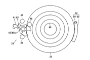
- FIG. 4 is a view for explaining the configuration of the third arm drive mechanism 12 from the EE direction of FIG.
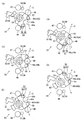
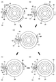
- FIG. 5 is a diagram for explaining the operation of the second detection mechanism 33 shown in FIG.
- FIG. 6 is a view for explaining the detection state of the first detection mechanism 32 and the detection state of the second detection mechanism 33 in the rotation range of the third arm 6 shown in FIG.
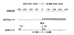
- FIG. 7 is a diagram for explaining the relationship between the rotation angle of the third arm 6 shown in FIG. 1 and the detection range of the optical sensor 61 and the detection range of the proximity sensor 59.
- the third arm drive mechanism 12 includes a first detection mechanism 32 and a second detection mechanism 33 for detecting the origin position of the third arm 6 in addition to the second drive motor 24 and the third reduction gear 25 described above. I have.
- the second detection mechanism 33 of the present embodiment also functions to restrict the rotation range of the third arm 6 with respect to the second arm 5.
- the second drive motor 24 (hereinafter referred to as “motor 24”) is a servo motor.
- the motor 24 is connected to a motor control unit 30 as motor control means for controlling the motor 24 (see FIG. 1).
- the motor 24 is attached to the distal end side of the second arm 5. Specifically, the motor 24 is fixed to the distal end side of the second arm 5 with respect to the place where the third reduction gear 25 is disposed.
- a pulley 34 is fixed to the output shaft of the motor 24.
- the third speed reducer 25 constitutes a third joint portion that connects the second arm 5 and the third arm 6.
- the third speed reducer 25 is a harmonic drive (registered trademark), and includes a wave generator 35, a circular spline 36, and a flex spline 37 as shown in FIG.
- the flex spline 37 is fixed to the third arm 6.
- the circular spline 36 is fixed to the distal end side of the second arm 5.
- a pulley 38 is fixed to the lower end of the wave generator 35.
- a belt 39 is stretched between the pulley 38 and the pulley 34 fixed to the output shaft of the motor 24.
- the wave generator 35 constitutes the input shaft of the third reduction gear 25
- the flex spline 37 constitutes the output shaft of the third reduction gear 25.
- a hollow shaft 40 disposed so as to pass through the center of the third reduction gear 25 is fixed to the distal end side of the second arm 5 with the vertical direction as the axial direction.
- the wave generator 35 is rotatably disposed on the outer peripheral side of the hollow shaft 40.
- predetermined wiring is routed using the inner peripheral side of the hollow shaft 40.
- the second detection mechanism 33 regulates a swinging member (swinging piece) 45 swingably attached to the second arm 5 and a swinging range of one side of the swinging member 45 in contact with the swinging member 45.
- an engaging pin 48 as an engaging member for swinging the swinging member 45.
- the third arm 6 can rotate 360 ° or more and less than 720 ° with respect to the second arm 5, and the second detection mechanism 33 rotates the third arm that rotates 360 ° or more and less than 720 °.
- the rotation range of 6 is regulated.
- the 3rd arm 6 of this form can be rotated about 700 degrees.
- the second detection mechanism 33 is a first magnetic holding unit that holds the swinging member 45 by a magnetic attractive force at a first restricting position 45A (see FIG. 5A) where the swinging member 45 contacts the stopper 46.
- a mechanism 51 and a second magnetic holding mechanism 52 that holds the swinging member 45 by a magnetic attractive force at a second restricting position 45B (see FIG. 5E) where the swinging member 45 contacts the stopper 47 are provided. ing.
- the engaging pin 48 is formed in a substantially cylindrical shape.
- the engagement pin 48 is fixed to the lower surface of the flex spline 37 via a predetermined member. That is, the engagement pin 48 is fixed to the third arm 6 via the flex spline 37 or the like.
- the engagement pin 48 engages with an engagement groove 45a described later formed in the swing member 45, and swings the swing member 45 between the first restriction position 45A and the second restriction position 45B.
- the swing member 45 is made of a nonmagnetic material and is formed in a block shape.
- the swing member 45 is swingably supported by a support shaft 53 fixed to the second arm 5, and can swing about the support shaft 53.
- the support shaft 53 is fixed to the second arm 5 with the vertical direction as the axial direction.
- the support shaft 53 is fixed to the second arm 5 on the outer side in the radial direction of the third reduction gear 25. That is, as shown in FIG. 4, when viewed from above and below, the swing center of the swing member 45 is outside the virtual circle C that is the locus of the center of the engagement pin 48 that rotates with the third arm 6. Has been placed. Further, the support shaft 53 is disposed on the proximal end side of the second arm 5 with respect to the third reduction gear 25.
- the swing member 45 is formed with an engagement groove 45a that engages with the engagement pin 48 when the swing member 45 swings between the first restricting position 45A and the second restricting position 45B.
- the engagement groove 45a is formed so as to have a substantially U shape when viewed from above and below, and a substantially semicircular concave curved surface 45b is formed on the side surface of the engagement groove 45a.
- the inner diameter of the concave curved surface 45 b is substantially equal to the outer diameter of the engagement pin 48.
- the swing member 45 of this embodiment is formed so that the shape when viewed from the vertical direction is a substantially U shape. Has been.
- the stoppers 46 and 47 are formed in a substantially cylindrical shape.
- the stopper 46 is fixed to the second arm 5 so as to be able to come into contact with one side surface of the swing member 45 in the swing direction of the swing member 45, and the stopper 47 is swung in the swing direction of the swing member 45. Is fixed to the second arm 5 so as to be able to come into contact with the other side surface of the swinging member 45. Further, the stoppers 46 and 47 are fixed to the second arm 5 so that the swing angle of the swing member 45 is, for example, about 20 ° to 30 °.
- the engagement pin 48 contacts the other side surface of the swing member 45 at the first restricting position 45A so as to press one side surface of the swing member 45 against the stopper 46.
- the flex spline 37 The rotation range on one side of the third arm 6 to which the engagement pin 48 is fixed is regulated through the like.
- the engagement pin 48 is provided on one side surface of the swing member 45 at the second restricting position 45B so as to press the other side surface of the swing member 45 against the stopper 47.
- the engaging pin 48 is disengaged from the engaging groove 45a in the process in which the swing member 45 rotates from the first restricting position 45A to the second restricting position 45B. Further, when the third arm 6 rotates about 330 ° clockwise in FIG. 5, for example, as shown in FIG. 5E, the engaging pin 48 comes into contact with one side surface of the swing member 45, The rotation of the third arm 6 in the clockwise direction is restricted.
- the engaging pin 48 is disengaged from the engaging groove 45a in the process in which the swing member 45 rotates from the second restricting position 45B to the first restricting position 45A. Further, when the third arm 6 rotates counterclockwise by, for example, about 330 ° in FIG. 5, the engaging pin 48 comes into contact with the other side surface of the swing member 45 as shown in FIG. The rotation of the third arm 6 in the counterclockwise direction is restricted.
- the engagement pin 48 when the third arm 6 rotates in the clockwise direction in FIG. 5, if the swing member 45 is in the first restricting position 45 ⁇ / b> A, the engagement pin 48 is located at the position where the swing member 45 is disposed. Even if it reaches, the engaging pin 48 can pass the place where the swinging member 45 is disposed while rotating the swinging member 45 to the second restricting position 45B, so that the third arm 6 further rotates. can do.
- the third arm 6 rotates clockwise in FIG.
- the third arm 6 rotates counterclockwise in FIG. 5, if the swinging member 45 is at the second restricting position 45 ⁇ / b> B, even if the engaging pin 48 reaches the position where the swinging member 45 is disposed, Since the engaging pin 48 can pass the place where the swinging member 45 is disposed while rotating the swinging member 45 to the first restricting position 45A, the third arm 6 can further rotate.
- the third arm 6 rotates counterclockwise in FIG. 5, if the swinging member 45 is present at the first restricting position 45 ⁇ / b> A, the stopper 46 is reached when the engaging pin 48 reaches the position where the swinging member 45 is disposed. The engaging pin 48 comes into contact with the swinging member 45 that comes into contact with the third arm 6, and the third arm 6 can no longer rotate.
- the swing member 45 when the swing member 45 is between the first restricting position 45A and the second restricting position 45B, as shown in FIG. 5 (C), it engages with a relatively wide range of the concave curved surface 45b.
- the swing member 45 and the engagement pin 48 are engaged so that the outer peripheral surface of the pin 48 is in contact with each other, and when viewed from the vertical direction, the center of curvature of the concave curved surface 45b and the center of the engagement pin 48 are Is almost the same.
- the second arm 5 is a support body that supports the third arm 6 that can rotate 360 ° or more and less than 720 °, and the third arm 6 can rotate 360 ° or more and less than 720 °. It is a rotating body.
- the first magnetic holding mechanism 51 is composed of a magnetic member 55 fixed to the swing member 45 and a permanent magnet 56 fixed to the second arm 5.
- the second magnetic holding mechanism 52 includes a magnetic member 57 fixed to the swing member 45 and a permanent magnet 58 fixed to the second arm 5.
- the magnetic members 55 and 57 are formed in a substantially cylindrical shape and are fixed to the lower surface of the swing member 45.
- the magnetic members 55 and 57 are fixed to the swinging member 45 on both sides of the engagement groove 45a so that the engagement groove 45a is sandwiched between the magnetic member 55 and the magnetic member 57.
- the permanent magnets 56 and 58 are formed in a substantially cylindrical shape.
- the permanent magnet 56 is fixed to the second arm 5 so as to be adjacent to the stopper 46
- the permanent magnet 58 is fixed to the second arm 5 so as to be adjacent to the stopper 47.
- the permanent magnets 56 and 58 are fixed to the second arm 5 so that a gap is formed between the lower surfaces of the magnetic members 55 and 57 and the upper surfaces of the permanent magnets 56 and 58 in the vertical direction.
- the second detection mechanism 33 includes an optical sensor 61 disposed so that the light emitting element and the light receiving element face each other, and a light shielding member 62 fixed to the swing member 45.
- the optical sensor 61 is fixed to the second arm 5.
- the light shielding member 62 is fixed to the swing member 45 so that the light emitting element and the light receiving element of the optical sensor 61 can be shielded.
- the light shielding member 62 of this embodiment is a second detected portion, and the optical sensor 61 is a second detecting portion that detects the light shielding member 62 that is the second detected portion.
- the swing member 45 when the swing member 45 is at the first restricting position 45A, the light shielding member 62 blocks between the light emitting element and the light receiving element of the optical sensor 61.
- the swing member 45 when the swing member 45 is in the second restricting position 45B, the light shielding member 62 is disengaged from between the light emitting element and the light receiving element of the optical sensor 61. That is, in this embodiment, the swing member 45 is attached to the second arm 5 so that the optical sensor 61 is switched on and off at one place in the rotation range of the third arm 6. Specifically, the swing member 45 is attached to the second arm 5 so that the optical sensor 61 is switched on and off at the center position of the rotation range of the third arm 6.
- the swing member 45 when the swing member 45 is in the first restricting position 45A, the light shielding member 62 blocks between the light emitting element and the light receiving element of the optical sensor 61, and the swing member 45 is in the second restricting position. Since the light shielding member 62 is disengaged from between the light emitting element and the light receiving element of the optical sensor 61 when in the position 45B, the swing member 45 is moved by the optical sensor 61 and the light shielding member 62 to the first restricting position 45A or the first position. It is detected which of the two restriction positions 45B is present.
- the first detection mechanism 32 includes a proximity sensor 59 fixed to the second arm 5 and a magnetic member 60 fixed to the third arm 6.
- the proximity sensor 59 is fixed to the second arm 5 so that the third speed reducer 25 is sandwiched between the swing member 45 and the proximity sensor 59. That is, the proximity sensor 59 is fixed to the second arm 5 on the distal end side of the second arm 5 with respect to the third speed reducer 25.
- the proximity sensor 59 is fixed to the second arm 5 so that the detection surface faces upward.
- the magnetic member 60 is formed in a flat plate shape and is fixed to the third arm 6 so as to pass above the detection surface of the proximity sensor 59.
- the magnetic member 60 is formed in a substantially arc shape, and the proximity sensor 59 can detect the magnetic member 60 within a range of a predetermined rotation angle of the third arm 6 with respect to the second arm 5.
- the magnetic member 60 of this embodiment is a first detected unit, and the proximity sensor 59 is a first detecting unit that detects the magnetic member 60 that is the first detected unit.
- the third arm 6 is formed of a nonmagnetic material such as aluminum, and the magnetic member 60 is detected by the proximity sensor 59, so that the third arm 6 is a predetermined amount with respect to the second arm 5. A state is detected.
- the proximity sensor 59 and the magnetic member 60 are arranged so that the magnetic member 60 is detected by the proximity sensor 59 at two places in the rotation range of the third arm 6.
- the boundary position of the third arm 6 is a position where the magnetic sensor 60 is detected by the proximity sensor 59 and the on / off of the optical sensor 61 is switched.
- the third arm 6 of the present embodiment can be rotated about 700 °, and the optical sensor 61 is turned on and off at the center position of the rotation range of the third arm 6.
- a moving member 45 is attached to the second arm 5. That is, the third arm 6 can rotate about 350 ° in the clockwise direction and about 350 ° in the counterclockwise direction around the boundary position where the on / off of the optical sensor 61 is switched.
- the magnetic member 60 is formed in a substantially arc shape. Specifically, the magnetic member 60 is formed in a substantially arc shape having the center of curvature at the center of the third reduction gear 25 (that is, the rotation center of the third arm 6), and the central angle ⁇ ( In FIG. 6A, the angle is about 44 °.
- the optical sensor 61 is switched to a boundary position where the on / off is switched.
- the proximity sensor 59 and the magnetic member 60 are arranged so that the counterclockwise end of the magnetic member 60 is applied to the proximity sensor 59 when the third arm 6 is present.
- the origin position shown in FIG. 6A and the position where the engagement pin 48 abuts on the swing member 45 and the rotation of the third arm 6 in the counterclockwise direction is restricted (shown in FIG. 6C).
- the proximity sensor 59 is between the position where the third arm 6 is rotated by 44 ° from the origin position (the position shown in FIG. 6B) and the origin position. Detects the magnetic member 60 and is turned on. Further, the position where the third arm 6 is rotated by 44 ° from the origin position (position shown in FIG. 6B) and the position where the rotation of the third arm 6 in the counterclockwise direction is restricted (shown in FIG. 6C). Between the position) and the proximity sensor 59 is turned off. Further, when the third arm 6 rotates between the origin position and the position where the counterclockwise rotation of the third arm 6 is restricted, the optical sensor 61 is turned on.
- the origin position shown in FIG. 6A and the position where the engagement pin 48 abuts on the swing member 45 and the clockwise rotation of the third arm 6 is restricted (position shown in FIG. 6E). ) Between the position where the third arm 6 is rotated 316 ° from the origin position (position shown in FIG. 6D) and the origin position, A position where the third arm 6 is rotated 316 ° from the origin position (position shown in FIG. 6D) and a position where the clockwise rotation of the third arm 6 is restricted (shown in FIG. 6E) is turned off. The position sensor 59 is turned on. Further, when the third arm 6 rotates between the origin position and the position where the clockwise rotation of the third arm 6 is restricted, the optical sensor 61 is turned off.
- the rotation angle of the third arm 6 at the boundary position where the on / off of the optical sensor 61 is switched is set to “0”, and the boundary position where the on / off of the optical sensor 61 is switched and the third arm 6 are rotated counterclockwise.
- the rotation angle of the third arm 6 with respect to the regulated position is a positive angle, the boundary position where the on / off of the optical sensor 61 is switched, and the position where the clockwise rotation of the third arm 6 is regulated.
- the rotation angle of the third arm 6 is set to a negative angle
- the relationship between the rotation angle of the third arm 6 and the detection range of the optical sensor 61 and the detection range of the proximity sensor 59 is summarized in FIG. It becomes like this.
- the second arm 5, the third arm 6, the motor 24, the motor control unit 30, the first detection mechanism 32, the second detection mechanism 33, and the like constitute a rotation mechanism.
- FIG. 8 is a diagram for explaining a method of returning the origin position of the third arm 6 shown in FIG.
- the third arm 6 can rotate about 700 ° with respect to the second arm 5, and the third arm 6 is 44 ° from the origin position within the rotation range of the third arm 6.
- the proximity sensor 59 between the rotated position and the origin position, and between the position where the third arm 6 is rotated 316 ° from the origin position and the position where the clockwise rotation of the third arm 6 is restricted.
- the proximity sensor 59 and the magnetic member 60 are arranged so that the magnetic member 60 is detected. Therefore, as the state at the moment when the magnetic member 60 is detected by the proximity sensor 59, as shown in FIG. 6 (A), the state where the third arm 6 is at the origin position and as shown in FIG. 6 (D).
- There are two states that is, the state in which the swing member 45 is in the second restricting position 45B. That is, in this embodiment, the origin position of the third arm 6 cannot be detected only by the first detection mechanism 32.
- the motor control unit 30 grasps the rotational position of the motor 24 (that is, the rotational position of the third arm 6).
- the control unit 30 may lose sight of the rotational position of the third arm 6. In this case, it is necessary to return the third arm 6 to the origin position.
- the origin position of the third arm 6 cannot be accurately detected only by the first detection mechanism 32, only the first detection mechanism 32 is used. Therefore, the third arm 6 cannot be returned to the origin position. Therefore, in the present embodiment, the third arm 6 is returned to the origin position using the first detection mechanism 32 and the second detection mechanism 33. Specifically, the third arm 6 is returned to the origin position as follows.
- the third arm 6 When returning the third arm 6 to the origin position, first, based on the detection state of the optical sensor 61, the third arm 6 is rotated to a position where the on / off of the optical sensor 61 is switched (first rotation step). That is, when returning the third arm 6 to the origin position, the motor control unit 30 first confirms the detection state of the optical sensor 61 and, based on the detection state of the optical sensor 61, the optical sensor 61. The motor 24 is controlled so that the third arm 6 rotates to a position where the on / off of the motor is switched.
- the optical sensor 61 when the third arm 6 is about to return to the origin, as shown in FIG. 8A, the optical sensor 61 is in a state where the swing member 45 is in the second restricting position 45B.
- the third arm 6 When is turned off, as shown in FIG. 8C, the third arm 6 is rotated counterclockwise to a position where the on / off of the optical sensor 61 is switched.
- FIG. 8B when the third arm 6 is returned to the origin, the optical sensor 61 is turned on with the swing member 45 at the first restricting position 45A. Sometimes, the third arm 6 is rotated clockwise until the optical sensor 61 is turned on and off.
- the third arm 6 is rotated counterclockwise, and the third arm 6 is rotated within a range where the magnetic sensor 60 is detected by the proximity sensor 59 (second rotation). Step). That is, as shown in FIG. 7, while rotating the third arm 6 to the “on side” in which the proximity sensor 59 is turned on within the range of the positive rotation angle of the third arm 6, the proximity sensor 59 is turned on. The third arm 6 is rotated within the range. That is, the motor control unit 30 controls the motor 24 so that the third arm 6 rotates counterclockwise and within a range in which the magnetic member 60 is detected by the proximity sensor 59.
- the third arm 6 is rotated clockwise by a predetermined angle until the magnetic member 60 is no longer detected by the proximity sensor 59 (third rotation step). That is, as shown in FIG. 7, the third arm 6 is rotated to the “off side” which is the opposite side of the “on side”, and at the same time, at least until the proximity sensor 59 switches from on to off.
- the arm 6 is rotated. That is, the motor control unit 30 controls the motor 24 so that the third arm 6 rotates clockwise by a predetermined angle until the magnetic sensor 60 is no longer detected by the proximity sensor 59. In the present embodiment, for example, the third arm 6 is rotated clockwise by about 10 °.
- the third arm 6 is rotated counterclockwise until the magnetic member 60 is detected by the proximity sensor 59 (that is, until the proximity sensor 59 switches from off to on again).
- (4th rotation step) That is, the motor control unit 30 controls the motor 24 so that the third arm 6 rotates counterclockwise until the magnetic member 60 is detected by the proximity sensor 59.
- the fourth rotation step ends, the third arm 6 returns to the origin position.
- the swing member 45 is attached to the second arm 5 so that the optical sensor 61 is switched on and off at one place in the rotation range of the third arm 6.
- the third sensor 6 when the third arm 6 is returned to the origin position, first, in the first rotation step, the third sensor 6 is moved to the position where the on / off of the optical sensor 61 is switched based on the detection state of the optical sensor 61.
- the arm 6 is rotated, and in the subsequent second rotation step, the third arm 6 is rotated counterclockwise, and the third arm 6 is rotated within a range in which the magnetic member 60 is detected by the proximity sensor 59.
- the third arm 6 is rotated clockwise to a position where the magnetic sensor 60 is no longer detected by the proximity sensor 59, and in the subsequent fourth rotation step, the magnetic sensor 60 is detected by the proximity sensor 59. Until the third arm 6 is rotated counterclockwise.
- the third arm 6 is appropriately moved to the origin position. It becomes possible to return. That is, when the boundary position where the on / off of the proximity sensor 59 is switched and the boundary position where the on / off of the optical sensor 61 is switched is the origin position of the third arm 6, the optical sensor 61, the light shielding member 62, and The detection state of the optical sensor 61 when the third arm 6 is at the origin position may become unstable due to the product accuracy or mounting accuracy of the swing member 45 or the response accuracy of the optical sensor 61. is there.
- the third arm 6 when the third arm 6 is returned to the origin position using the on / off state of the proximity sensor 59 and the on / off state of the optical sensor 61, the third arm 6 is appropriately returned to the origin position. There can be situations where you can't. In this embodiment, since the third arm 6 can be returned to the origin position regardless of the on / off state of the optical sensor 61, it is a boundary position where the on / off of the proximity sensor 59 is switched, and the optical sensor 61 Even when the boundary position where the on / off switching is performed is the origin position of the third arm 6, the third arm 6 can be appropriately returned to the origin position.
- the third arm 6 can be accurately returned to the origin position by lowering the rotation speed of the third arm 6 when the third arm 6 is returned to the origin position in the fourth rotation step. It becomes possible.
- the third arm 6 when the third arm 6 is returned to the origin position, first, the third arm 6 is rotated to the position where the on / off of the optical sensor 61 is switched in the first rotation step. If a certain operation (that is, the operation from the second rotation step to the fourth rotation step) is performed with reference to one position in the rotation range of the third arm 6 where the on / off of the sensor 61 is switched, the third arm 6 is set to the origin. It is possible to reliably return to the position. Therefore, in this embodiment, it is possible to reliably return the third arm 6 to the origin position in a short time.
- a certain operation that is, the operation from the second rotation step to the fourth rotation step
- the rocking member 45 is held at the first restricting position 45A by the magnetic attractive force of the first magnetic holding mechanism 51, and the rocking member 45 is second restricted by the magnetic attractive force of the second magnetic holding mechanism 52. It is held at position 45B. Therefore, in this embodiment, the swinging member 45 can be prevented from wobbling and the detection accuracy of the second detection mechanism 33 can be increased. In addition, since the swing member 45 is held by the magnetic attractive force, even if the swing member 45 is held at the first restricting position 45A or the second restricting position 45B so that the swing member 45 does not wobble, The member for holding the swing member 45 at the first restricting position 45A or the second restricting position 45B does not need to contact the swing member 45. Therefore, in the present embodiment, it is possible to suppress the generation of dust and the generation of abnormal noise accompanying the swing of the swing member 45 that swings between the first restricting position 45A and the second restricting position 45B.
- the engagement pin 48 can abut against the other side surface of the swing member 45 at the first restricting position 45 ⁇ / b> A so as to press one side surface of the swing member 45 against the stopper 46. 47, the other side surface of the swinging member 45 can be pressed against one side surface of the swinging member 45 at the second restricting position 45B. It also functions to regulate the rotation range of the three arms 6. Therefore, in this embodiment, it is not necessary to provide a separate mechanism for restricting the rotation range of the third arm 6. Therefore, in this embodiment, the configuration of the robot 1 can be simplified.
- the boundary position where the on / off of the proximity sensor 59 is switched, and the boundary position where the on / off of the optical sensor 61 is switched is the origin position of the third arm 6.
- the optical sensor 61 is on, and the engaging pin 48 has reached the other side surface of the swing member 45 at the first restricting position 45A.
- the boundary position where the proximity sensor 59 is switched on and off may be the origin position of the third arm 6.
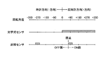
- the relationship between the rotation angle of the third arm 6 and the detection range of the optical sensor 61 and the detection range of the proximity sensor 59 is summarized as shown in FIG.
- the motor control unit 30 loses sight of the rotation position of the third arm 6 and returns the third arm 6 to the origin position, the first rotation step to the fourth rotation step described above are sequentially executed,
- the three arms 6 may be returned to the origin position.
- the third arm 6 is moved counterclockwise until the magnetic member 60 is detected by the proximity sensor 59.
- the third arm 6 may be returned to the origin position by rotating.
- the optical sensor 61 is on, and The state in which the magnetic member 60 is arranged on the clockwise side of the proximity sensor 59, and the optical sensor 61 is on and the counterclockwise side of the proximity sensor 59 as shown in FIG. It is conceivable that the magnetic member 60 is disposed on the surface.
- the third arm 6 is rotated until the magnetic member 60 is detected by the proximity sensor 59, and the on / off state of the optical sensor 61 when the magnetic member 60 is detected by the proximity sensor 59 is confirmed.
- the third arm 6 can be returned to the origin position in a short time by rotating the third arm 6 counterclockwise.
- the state of the third arm 6 when the magnetic member 60 is detected by the proximity sensor 59 becomes the state shown in FIG. 9D.
- the third arm 6 cannot be returned to the origin position unless the third arm 6 is rotated counterclockwise again.
- the optical sensor 61 is on, and therefore the third arm is utilized by utilizing the on / off state of the optical sensor 61.
- the rotation direction for returning 6 to the origin position cannot be determined. Therefore, by rotating the third arm 6 until the magnetic member 60 is detected by the proximity sensor 59 and confirming the on / off state of the optical sensor 61 when the magnetic member 60 is detected by the proximity sensor 59, the third arm 6 is confirmed.
- the third arm 6 cannot be reliably returned to the origin position in a short time depending on the origin position of the third arm 6.
- the third arm 6 when returning the third arm 6 to the origin position, first, when the third arm 6 is rotated to a position where the on / off of the optical sensor 61 is switched, the on / off of the optical sensor 61 is switched.
- the third arm 6 can be reliably returned to the origin position by performing a certain operation with reference to one position in the rotation range of the three arms 6. That is, the third arm 6 is rotated until the magnetic sensor 60 is detected by the proximity sensor 59, and the on / off state of the optical sensor 61 when the magnetic sensor 60 is detected by the proximity sensor 59 is confirmed.
- the third arm 6 can be reliably returned to the origin position in a short time.
- the optical sensor 61 is off and the engagement pin 48 does not reach one side surface of the swing member 45 at the second restricting position 45B.
- the boundary position where the on / off of the proximity sensor 59 is switched may be the origin position of the third arm 6.
- the relationship between the rotation angle of the third arm 6 and the detection range of the optical sensor 61 and the detection range of the proximity sensor 59 is summarized as shown in FIG.
- the motor control unit 30 loses sight of the rotational position of the third arm 6 and returns the third arm 6 to the origin position, first, based on the detection state of the optical sensor 61, the optical sensor 61 is turned on / off.
- the third arm 6 is rotated to a position where the position is switched (first rotation step). Thereafter, the third arm 6 is rotated clockwise, and the third arm 6 is rotated within a range where the magnetic sensor 60 is detected by the proximity sensor 59 (second rotation step). That is, as shown in FIG. 11, while rotating the third arm 6 to the “on side” where the proximity sensor 59 is turned on within the range of the negative rotation angle of the third arm 6, the proximity sensor 59 is turned on.
- the third arm 6 is rotated within the range.
- the third arm 6 is rotated counterclockwise by a predetermined angle until the magnetic sensor 60 is no longer detected by the proximity sensor 59 (third rotation step). That is, as shown in FIG. The third arm 6 is rotated to the “off side”, and the third arm 6 is rotated at a predetermined angle at least until the proximity sensor 59 is switched from on to off. Thereafter, when the third arm 6 is rotated counterclockwise until the magnetic member 60 is detected by the proximity sensor 59 (fourth rotation step), the third arm 6 returns to the origin position. In this case, when the third arm 6 is returned to the home position, the third arm 6 is moved clockwise until the magnetic member 60 is detected by the proximity sensor 59 after the first rotation step is performed. And the third arm 6 may be returned to the origin position.
- the optical sensor 61 is on, and the engagement pin 48 is in contact with the other side surface of the swing member 45 at the first restriction position 45A, and
- the boundary position where the on / off of the proximity sensor 59 is switched may be the origin position of the third arm 6.
- the magnetic sensor 60 is detected by the proximity sensor 59.
- the third arm 6 is rotated until the magnetic sensor 60 is detected by the proximity sensor 59, and the on / off state of the optical sensor 61 when the magnetic member 60 is detected is returned to the origin position.
- the proximity sensor 59 and the magnetic member 60 are arranged so that the magnetic member 60 is detected by the proximity sensor 59 at two locations in the rotation range of the third arm 6.
- the proximity sensor 59 and the magnetic member 60 may be arranged so that the magnetic member 60 is detected by the proximity sensor 59 at one place in the rotation range of the third arm 6.
- the third arm 6 in the second rotation step, is rotated counterclockwise, and the third arm 6 is rotated within a range in which the magnetic member 60 is detected by the proximity sensor 59.
- the third arm 6 in the second rotation step, may be rotated counterclockwise, and the third arm 6 may be rotated by a predetermined angle until the magnetic sensor 60 is no longer detected by the proximity sensor 59.
- the third arm 6 in the third rotation step, is rotated clockwise, and after the magnetic sensor 60 is detected by the proximity sensor 59, until the magnetic sensor 60 is no longer detected by the proximity sensor 59 again.
- the third arm 6 may be rotated by a predetermined angle.
- the proximity sensor 59 is fixed to the second arm 5 and the magnetic member 60 is fixed to the third arm 6.
- the proximity sensor 59 is fixed to the third arm 6 and the magnetic member 60 is The two arms 5 may be fixed.
- the optical sensor 61 is fixed to the second arm 5 and the light shielding member 62 is fixed to the swing member 45.
- the optical sensor 61 is fixed to the swing member 45 and the light shielding member. 62 may be fixed to the second arm 5.
- the first detection mechanism 32 includes the proximity sensor 59.
- the first detection mechanism 32 may include another sensor such as an optical sensor instead of the proximity sensor 59. good.
- the second detection mechanism 33 may include another sensor such as a proximity sensor instead of the optical sensor 61.
- the magnetic member 55 is fixed to the swing member 45 and the permanent magnet 56 is fixed to the second arm 5.
- the magnetic member 55 is fixed to the second arm 5 and the permanent magnet 56 swings. It may be fixed to the member 45.
- the magnetic member 57 is fixed to the swing member 45 and the permanent magnet 58 is fixed to the second arm 5, but the magnetic member 57 is fixed to the second arm 5 and the permanent magnet 58. May be fixed to the swing member 45.
- the swing member 45 is made of a magnetic material, the magnetic members 55 and 57 may not be fixed to the swing member 45.
- first magnetic holding mechanism 51 and the second magnetic holding mechanism 52 may include a permanent magnet fixed to the swing member 45 instead of the magnetic members 55 and 57.
- the swinging member 45 at the first restricting position 45A or the second restricting position 45B is generated by a magnetic attractive force generated between the permanent magnet fixed to the swinging member 45 and the permanent magnets 56 and 58. So that the permanent magnet fixed to the swing member 45 is magnetized and arranged.
- the swing member 45 is held at the first restricting position 45A and the second restricting position 45B by the magnetic repulsive force generated between the permanent magnet fixed to the swing member 45 and the permanent magnets 56 and 58.
- a permanent magnet fixed to the swing member 45 is magnetized and arranged.
- the second detection mechanism 33 also functions to restrict the rotation range of the third arm 6 relative to the second arm 5.
- a mechanism for restricting the rotation range of the third arm 6 relative to the second arm 5 may be provided separately.
- the first detection mechanism 32 and the second detection mechanism 33 are provided for detecting the origin position of the third arm 6.
- the first detection mechanism 32 and the second detection mechanism 33 are used to The origin position may be detected.
- the origin position of the second arm 5 is set using the first detection mechanism 32 and the second detection mechanism 33. It may be detected.
- the hands 7 and 8 rotate 360 ° or more and less than 720 ° with respect to the third arm 6, the origin positions of the hands 7 and 8 are set using the first detection mechanism 32 and the second detection mechanism 33. It may be detected.
- the robot 1 is a robot for transporting the semiconductor wafer 2, but the robot 1 may be a transport robot for transporting other transport objects such as a glass substrate for liquid crystal.
- An industrial robot other than a transfer robot such as an assembly robot may be used. That is, the first detection mechanism 32 and the second detection mechanism 33 may be used for a robot other than the robot 1. Further, the first detection mechanism 32 and the second detection mechanism 33 may be used in various devices other than a robot having a rotating body that can rotate 360 ° or more and 720 or more with respect to the support.
Landscapes
- Engineering & Computer Science (AREA)
- Robotics (AREA)
- Mechanical Engineering (AREA)
- Manipulator (AREA)
Abstract
Description
図1は、本発明の実施の形態にかかる産業用ロボット1の概略側面図である。図2は、図1に示す産業用ロボット1が使用される半導体製造システム16の概略平面図である。
図3は、図1に示す第3アーム駆動機構12の構成を説明するための縦断面図である。
図4は、図3のE-E方向から第3アーム駆動機構12の構成を説明するための図である。図5は、図3に示す第2検出機構33の動作を説明するための図である。図6は、図1に示す第3アーム6の回転範囲における第1検出機構32の検出状態および第2検出機構33の検出状態を説明するための図である。図7は、図1に示す第3アーム6の回転角度と、光学式センサ61の検出範囲および近接センサ59の検出範囲との関係を説明するための図である。
図8は、図1に示す第3アーム6の原点位置復帰方法を説明するための図である。
以上説明したように、本形態では、第3アーム6の回転範囲の1箇所で、光学式センサ61のオンオフが切り替わるように、揺動部材45が第2アーム5に取り付けられている。また、本形態では、第3アーム6を原点位置へ復帰させるときに、まず、第1回転ステップで、光学式センサ61の検出状態に基づいて、光学式センサ61のオンオフが切り替わる位置まで第3アーム6を回転させ、その後の第2回転ステップで、反時計方向へ第3アーム6を回転させるとともに、近接センサ59で磁性部材60が検出される範囲内へ第3アーム6を回転させ、その後の第3回転ステップで、近接センサ59で磁性部材60が検出されなくなる位置まで時計方向へ第3アーム6を回転させ、その後の第4回転ステップで、近接センサ59で磁性部材60が検出されるまで第3アーム6を反時計方向に回転させている。
上述した形態は、本発明の好適な形態の一例ではあるが、これに限定されるものではなく本発明の要旨を変更しない範囲において種々変形実施が可能である。
3 本体部
4 第1アーム
5 第2アーム(支持体、回転機構の一部)
6 第3アーム(回転体、回転機構の一部)
7、8 ハンド
24 モータ(第2駆動用モータ、回転機構の一部)
30 モータ制御部(モータ制御手段、回転機構の一部)
32 第1検出機構(回転機構の一部)
33 第2検出機構(回転機構の一部)
45 揺動部材
45A 第1規制位置
45B 第2規制位置
46 ストッパ(第1規制部材)
47 ストッパ(第2規制部材)
48 係合ピン(係合部材)
51 第1磁気保持機構
52 第2磁気保持機構
59 近接センサ(第1検出部)
60 磁性部材(第1被検出部)
61 光学式センサ(第2検出部)
62 遮光部材(第2被検出部)
Claims (8)
- 支持体と、前記支持体に対して360°以上かつ720°未満回転可能な回転体と、前記回転体を回転させるモータと、前記回転体の原点位置を検出するための第1検出機構および第2検出機構と、前記モータを制御するモータ制御手段とを備え、
前記第1検出機構は、前記支持体または前記回転体のいずれか一方に固定または形成される第1被検出部と、前記支持体または前記回転体のいずれか他方に固定され前記第1被検出部を検出する第1検出部とを備え、
前記第2検出機構は、前記支持体に揺動可能に取り付けられる揺動部材と、前記回転体に固定または形成されるとともに、前記揺動部材に係合して前記揺動部材を揺動させる係合部材と、前記揺動部材または前記支持体のいずれか一方に固定または形成される第2被検出部と、前記揺動部材または前記支持体のいずれか他方に固定され前記第2被検出部を検出する第2検出部とを備え、
前記回転体の回転範囲の1箇所または2箇所で、前記第1検出部によって前記第1被検出部が検出されるように、前記第1被検出部および前記第1検出部が配置され、
前記回転体の回転範囲の1箇所で、前記第2検出部のオンオフが切り替わるように、前記揺動部材が前記支持体に取り付けられ、
前記モータ制御手段は、前記回転体を原点位置へ復帰させるときに、まず、前記第2検出部のオンオフが切り替わる位置まで前記回転体が回転するように前記モータを制御することを特徴とする回転機構。 - 前記モータ制御手段は、前記第2検出部のオンオフが切り替わる位置まで前記回転体が回転した後に、所定の第1回転方向へかつ前記第1検出部で前記第1被検出部が検出される範囲内へ前記回転体が回転し、その後、前記第1検出部で前記第1被検出部が検出されなくなるまで前記第1回転方向の逆方向となる第2回転方向へ前記回転体が回転し、かつ、その後、前記第1検出部で前記第1被検出部が検出されるまで前記第1回転方向へ前記回転体が回転するように、前記モータを制御して、前記回転体を原点位置へ復帰させることを特徴とする請求項1記載の回転機構。
- 前記第2検出機構は、前記支持体に固定または形成されるとともに前記揺動部材に当接して前記揺動部材の一方側の揺動範囲を規制する第1規制部材と、前記支持体に固定または形成されるとともに前記揺動部材に当接して前記揺動部材の他方側の揺動範囲を規制する第2規制部材とを備え、
前記係合部材は、前記揺動部材が前記第1規制部材に当接する第1規制位置と前記揺動部材が前記第2規制部材に当接する第2規制位置との間で前記揺動部材を揺動させ、
前記第2検出機構は、前記第2被検出部と前記第2検出部とによって、前記揺動部材が前記第1規制位置または前記第2規制位置のいずれにあるのかを検出することを特徴とする請求項1または2記載の回転機構。 - 前記第2検出機構は、磁気吸引力または磁気反発力によって前記第1規制位置で前記揺動部材を保持する第1磁気保持機構と、磁気吸引力または磁気反発力によって前記第2規制位置で前記揺動部材を保持する第2磁気保持機構とを備えることを特徴とする請求項3記載の回転機構。
- 前記係合部材は、前記第1規制位置にある前記揺動部材を前記第1規制部材に押し付けるように前記揺動部材に当接可能であるとともに、前記第2規制位置にある前記揺動部材を前記第2規制部材に押し付けるように前記揺動部材に当接可能であることを特徴とする請求項3または4記載の回転機構。
- 請求項1から5のいずれかに記載の回転機構を備える産業用ロボットであって、
本体部と、その基端側が前記本体部に回動可能に取り付けられる第1アームと、その基端側が前記第1アームの先端側に回動可能に取り付けられる前記支持体としての第2アームと、その基端側が前記第2アームの先端側に回転可能に取り付けられる前記回転体としての第3アームと、その基端側が前記第3アームの先端側に回転可能に取り付けられるハンドとを備えることを特徴とする産業用ロボット。 - 支持体と、前記支持体に対して360°以上かつ720°未満回転可能な回転体と、前記回転体の原点位置を検出するための第1検出機構および第2検出機構とを備え、
前記第1検出機構は、前記支持体または前記回転体のいずれか一方に固定または形成される第1被検出部と、前記支持体または前記回転体のいずれか他方に固定され前記第1被検出部を検出する第1検出部とを備え、
前記第2検出機構は、前記支持体に揺動可能に取り付けられる揺動部材と、前記回転体に固定または形成されるとともに、前記揺動部材に係合して前記揺動部材を揺動させる係合部材と、前記揺動部材または前記支持体のいずれか一方に固定または形成される第2被検出部と、前記揺動部材または前記支持体のいずれか他方に固定され前記第2被検出部を検出する第2検出部とを備え、
前記回転体の回転範囲の1箇所または2箇所で、前記第1検出部によって前記第1被検出部が検出されるように、前記第1被検出部および前記第1検出部が配置され、
前記回転体の回転範囲の1箇所で、前記第2検出部のオンオフが切り替わるように、前記揺動部材が前記支持体に取り付けられる回転機構における回転体の原点位置復帰方法であって、
前記回転体を原点位置へ復帰させるときに、まず、前記第2検出部のオンオフが切り替わる位置まで前記回転体を回転させる第1回転ステップを実行することを特徴とする回転体の原点位置復帰方法。 - 前記第1回転ステップ後に、所定の第1回転方向へかつ前記第1検出部で前記第1被検出部が検出される範囲内へ前記回転体を回転させる第2回転ステップと、前記第2回転ステップ後に、前記第1検出部で前記第1被検出部が検出されなくなるまで前記第1回転方向の逆方向となる第2回転方向へ前記回転体を回転させる第3回転ステップと、前記第3回転ステップ後に、前記第1検出部で前記第1被検出部が検出されるまで前記回転体を前記第1回転方向へ回転させる第4回転ステップとを備えることを特徴とする請求項7記載の回転体の原点位置復帰方法。
Priority Applications (3)
| Application Number | Priority Date | Filing Date | Title |
|---|---|---|---|
| CN2012800023727A CN103068534A (zh) | 2011-04-27 | 2012-04-17 | 旋转机构、工业用机器人及旋转体的原点位置复位方法 |
| KR1020137003891A KR101469397B1 (ko) | 2011-04-27 | 2012-04-17 | 회전기구, 산업용 로봇 및 회전체의 원점위치 복귀방법 |
| US13/816,007 US9278450B2 (en) | 2011-04-27 | 2012-04-17 | Rotating mechanism, industrial robot and method for returning rotating body to original position |
Applications Claiming Priority (2)
| Application Number | Priority Date | Filing Date | Title |
|---|---|---|---|
| JP2011-098936 | 2011-04-27 | ||
| JP2011098936A JP5818345B2 (ja) | 2011-04-27 | 2011-04-27 | 回転機構、産業用ロボットおよび回転体の原点位置復帰方法 |
Publications (1)
| Publication Number | Publication Date |
|---|---|
| WO2012147557A1 true WO2012147557A1 (ja) | 2012-11-01 |
Family
ID=47072079
Family Applications (1)
| Application Number | Title | Priority Date | Filing Date |
|---|---|---|---|
| PCT/JP2012/060306 Ceased WO2012147557A1 (ja) | 2011-04-27 | 2012-04-17 | 回転機構、産業用ロボットおよび回転体の原点位置復帰方法 |
Country Status (5)
| Country | Link |
|---|---|
| US (1) | US9278450B2 (ja) |
| JP (1) | JP5818345B2 (ja) |
| KR (1) | KR101469397B1 (ja) |
| CN (1) | CN103068534A (ja) |
| WO (1) | WO2012147557A1 (ja) |
Families Citing this family (10)
| Publication number | Priority date | Publication date | Assignee | Title |
|---|---|---|---|---|
| US9718187B2 (en) * | 2014-06-11 | 2017-08-01 | Canon Kabushiki Kaisha | Robot controlling method, robot apparatus, program, recording medium, and method for manufacturing assembly component |
| CN107000203B (zh) * | 2014-12-26 | 2020-04-10 | 川崎重工业株式会社 | 机械臂 |
| CN108136603B (zh) * | 2015-12-28 | 2021-04-06 | Abb瑞士股份有限公司 | 止动器装置、旋转关节以及机器人 |
| JP6817841B2 (ja) * | 2017-02-17 | 2021-01-20 | 日本電産シンポ株式会社 | 電動機付き減速機 |
| JP6914811B2 (ja) * | 2017-11-09 | 2021-08-04 | 日本電産サンキョー株式会社 | 水平多関節型ロボット及びその原点復帰方法 |
| JP6705794B2 (ja) * | 2017-12-01 | 2020-06-03 | ファナック株式会社 | ストッパを備えるロボット |
| CN110561397A (zh) * | 2018-06-05 | 2019-12-13 | 日本电产三协(浙江)有限公司 | 工业用机器人 |
| CN113195178A (zh) * | 2019-01-23 | 2021-07-30 | Abb瑞士股份有限公司 | 用于管理机器人手臂的方法和装置 |
| JP7293713B2 (ja) * | 2019-02-25 | 2023-06-20 | 京セラドキュメントソリューションズ株式会社 | 把持機構及び組立装置 |
| DE112021008316T5 (de) * | 2021-12-22 | 2024-10-24 | Fanuc Corporation | Bewegungsmechanismusanhaltevorrichtung und roboter |
Citations (11)
| Publication number | Priority date | Publication date | Assignee | Title |
|---|---|---|---|---|
| JPH024792U (ja) * | 1988-06-20 | 1990-01-12 | ||
| JPH02232191A (ja) * | 1989-02-28 | 1990-09-14 | Pentel Kk | ダイレクトドライブロボットのストッパ装置 |
| JPH0366585A (ja) * | 1989-08-02 | 1991-03-22 | Fujitsu Ltd | 関節型ロボット |
| JPH05177578A (ja) * | 1991-12-27 | 1993-07-20 | Suzuki Motor Corp | 回転体の回転角制御装置 |
| JPH063581U (ja) * | 1992-06-19 | 1994-01-18 | トキコ株式会社 | 位置表示装置 |
| JPH0729273B2 (ja) * | 1990-01-10 | 1995-04-05 | 株式会社神戸製鋼所 | 工業用ロボットの保護装置 |
| JP2003170384A (ja) * | 2001-12-04 | 2003-06-17 | Rorze Corp | 平板状物の搬送用スカラ型ロボットおよび平板状物の処理システム |
| JP2003205488A (ja) * | 2002-01-11 | 2003-07-22 | Murata Mach Ltd | 旋回機構およびそれを備えた移載装置 |
| JP2003260684A (ja) * | 2002-03-07 | 2003-09-16 | Hitachi Hybrid Network Co Ltd | 移動体 |
| JP3648875B2 (ja) * | 1996-09-30 | 2005-05-18 | 日本精工株式会社 | 回転軸ストッパ機構 |
| JP3776345B2 (ja) * | 2001-10-04 | 2006-05-17 | 本田技研工業株式会社 | 自動原点合わせ方法及び自動原点確認方法 |
Family Cites Families (15)
| Publication number | Priority date | Publication date | Assignee | Title |
|---|---|---|---|---|
| JPS6172584U (ja) * | 1984-10-16 | 1986-05-17 | ||
| JPH024792A (ja) | 1988-06-23 | 1990-01-09 | Konica Corp | m−ジオキシノ〔e〕ベンゾ−m−ジオキサン系化合物及び該化合物を用いた有機着色物質の光褪色防止方法 |
| JPH05289763A (ja) * | 1992-04-14 | 1993-11-05 | Fujitsu Ltd | 回転軸のメカニカルストッパ |
| JPH063581A (ja) | 1992-06-19 | 1994-01-14 | Nikon Corp | 自動焦点調節装置 |
| JPH0729273A (ja) | 1993-05-11 | 1995-01-31 | Sanyo Electric Co Ltd | 磁気記録再生装置 |
| US5839322A (en) * | 1996-01-26 | 1998-11-24 | Genmark Automation | Robotic arm rotation controller |
| JP2003117877A (ja) * | 2001-10-17 | 2003-04-23 | Japan Servo Co Ltd | 多関節型の産業用ロボット |
| TW200502070A (en) * | 2003-07-04 | 2005-01-16 | Rorze Corp | Carrying apparatus and carrying control method for sheet-like objects |
| KR100582697B1 (ko) * | 2003-07-16 | 2006-05-23 | 동경 엘렉트론 주식회사 | 피처리 기판의 반송 장치 및 회전 위치를 검출하는 기능을갖는 구동 기구 |
| JP2006205264A (ja) * | 2005-01-25 | 2006-08-10 | Jel:Kk | 基板搬送装置 |
| JP4605560B2 (ja) * | 2005-12-05 | 2011-01-05 | 日本電産サンキョー株式会社 | 産業用ロボット |
| CN101190525A (zh) * | 2006-11-22 | 2008-06-04 | 富士迈半导体精密工业(上海)有限公司 | 自动校正机械手臂 |
| JP5102564B2 (ja) * | 2007-08-31 | 2012-12-19 | 日本電産サンキョー株式会社 | 産業用ロボット |
| JP5480562B2 (ja) * | 2009-08-26 | 2014-04-23 | 日本電産サンキョー株式会社 | 産業用ロボット |
| JP5818346B2 (ja) * | 2011-04-27 | 2015-11-18 | 日本電産サンキョー株式会社 | 回転体の回転範囲規制機構および産業用ロボット |
-
2011
- 2011-04-27 JP JP2011098936A patent/JP5818345B2/ja active Active
-
2012
- 2012-04-17 KR KR1020137003891A patent/KR101469397B1/ko active Active
- 2012-04-17 WO PCT/JP2012/060306 patent/WO2012147557A1/ja not_active Ceased
- 2012-04-17 US US13/816,007 patent/US9278450B2/en active Active
- 2012-04-17 CN CN2012800023727A patent/CN103068534A/zh active Pending
Patent Citations (11)
| Publication number | Priority date | Publication date | Assignee | Title |
|---|---|---|---|---|
| JPH024792U (ja) * | 1988-06-20 | 1990-01-12 | ||
| JPH02232191A (ja) * | 1989-02-28 | 1990-09-14 | Pentel Kk | ダイレクトドライブロボットのストッパ装置 |
| JPH0366585A (ja) * | 1989-08-02 | 1991-03-22 | Fujitsu Ltd | 関節型ロボット |
| JPH0729273B2 (ja) * | 1990-01-10 | 1995-04-05 | 株式会社神戸製鋼所 | 工業用ロボットの保護装置 |
| JPH05177578A (ja) * | 1991-12-27 | 1993-07-20 | Suzuki Motor Corp | 回転体の回転角制御装置 |
| JPH063581U (ja) * | 1992-06-19 | 1994-01-18 | トキコ株式会社 | 位置表示装置 |
| JP3648875B2 (ja) * | 1996-09-30 | 2005-05-18 | 日本精工株式会社 | 回転軸ストッパ機構 |
| JP3776345B2 (ja) * | 2001-10-04 | 2006-05-17 | 本田技研工業株式会社 | 自動原点合わせ方法及び自動原点確認方法 |
| JP2003170384A (ja) * | 2001-12-04 | 2003-06-17 | Rorze Corp | 平板状物の搬送用スカラ型ロボットおよび平板状物の処理システム |
| JP2003205488A (ja) * | 2002-01-11 | 2003-07-22 | Murata Mach Ltd | 旋回機構およびそれを備えた移載装置 |
| JP2003260684A (ja) * | 2002-03-07 | 2003-09-16 | Hitachi Hybrid Network Co Ltd | 移動体 |
Also Published As
| Publication number | Publication date |
|---|---|
| CN103068534A (zh) | 2013-04-24 |
| JP5818345B2 (ja) | 2015-11-18 |
| KR20130046433A (ko) | 2013-05-07 |
| KR101469397B1 (ko) | 2014-12-04 |
| JP2012228753A (ja) | 2012-11-22 |
| US20140331807A1 (en) | 2014-11-13 |
| US9278450B2 (en) | 2016-03-08 |
Similar Documents
| Publication | Publication Date | Title |
|---|---|---|
| JP5818345B2 (ja) | 回転機構、産業用ロボットおよび回転体の原点位置復帰方法 | |
| JP5818346B2 (ja) | 回転体の回転範囲規制機構および産業用ロボット | |
| US20110135437A1 (en) | Horizontal multi-joint robot and transportation apparatus including the same | |
| JP6051021B2 (ja) | 産業用ロボットおよび産業用ロボットの制御方法 | |
| JP4930949B2 (ja) | 基板搬送装置 | |
| JP2013071186A (ja) | ハンドおよびロボット | |
| CN106796907B (zh) | 衬底搬送机器人及其运转方法 | |
| EP2364822A1 (en) | Industrial robot comprising a pendulum stopper on the base | |
| WO2012008321A1 (ja) | 産業用ロボット、産業用ロボットの制御方法および産業用ロボットの教示方法 | |
| JP2010162611A (ja) | 相対ティーチング方法 | |
| JP5339874B2 (ja) | ロボット装置及びその制御方法 | |
| JP2019520227A (ja) | ロボットの構成要素用の可動ハードストップ | |
| JP4595053B2 (ja) | 多関節型ロボット | |
| JPWO2018021178A1 (ja) | 産業用ロボット | |
| JP5013083B2 (ja) | 衝突トルク緩衝機構を備えた基板搬送ロボット | |
| JP2014037027A (ja) | 搬送装置 | |
| JP4648161B2 (ja) | ダブルアーム列式基板搬送用ロボット | |
| JP7550042B2 (ja) | ロボット及び教示方法 | |
| JP2024106800A (ja) | ロボットシステムおよび産業用ロボットの制御方法 | |
| JP2014065122A (ja) | パラレルリンクロボット | |
| JP2004323165A (ja) | 基板搬送装置 | |
| JP4253945B2 (ja) | ロボットハンドのチルト機構 | |
| JP4446816B2 (ja) | 基板角度位置補正装置 | |
| JP2009126706A (ja) | コンベヤ装置 | |
| JP2024028196A (ja) | 基板移送装置 |
Legal Events
| Date | Code | Title | Description |
|---|---|---|---|
| WWE | Wipo information: entry into national phase |
Ref document number: 201280002372.7 Country of ref document: CN |
|
| 121 | Ep: the epo has been informed by wipo that ep was designated in this application |
Ref document number: 12776464 Country of ref document: EP Kind code of ref document: A1 |
|
| ENP | Entry into the national phase |
Ref document number: 20137003891 Country of ref document: KR Kind code of ref document: A |
|
| NENP | Non-entry into the national phase |
Ref country code: DE |
|
| WWE | Wipo information: entry into national phase |
Ref document number: 13816007 Country of ref document: US |
|
| 122 | Ep: pct application non-entry in european phase |
Ref document number: 12776464 Country of ref document: EP Kind code of ref document: A1 |