WO2012147476A1 - Pompe d'alimentation en liquide et dispositif de régulation du débit - Google Patents
Pompe d'alimentation en liquide et dispositif de régulation du débit Download PDFInfo
- Publication number
- WO2012147476A1 WO2012147476A1 PCT/JP2012/059254 JP2012059254W WO2012147476A1 WO 2012147476 A1 WO2012147476 A1 WO 2012147476A1 JP 2012059254 W JP2012059254 W JP 2012059254W WO 2012147476 A1 WO2012147476 A1 WO 2012147476A1
- Authority
- WO
- WIPO (PCT)
- Prior art keywords
- diaphragm
- discharge
- flow rate
- pump
- liquid feed
- Prior art date
Links
- 239000007788 liquid Substances 0.000 title claims abstract description 128
- 238000006073 displacement reaction Methods 0.000 claims abstract description 44
- 230000007423 decrease Effects 0.000 claims abstract description 11
- 230000004044 response Effects 0.000 claims abstract description 8
- 238000005192 partition Methods 0.000 claims abstract description 3
- 238000005259 measurement Methods 0.000 claims description 23
- 239000012530 fluid Substances 0.000 claims description 8
- 230000002093 peripheral effect Effects 0.000 claims description 5
- 239000002245 particle Substances 0.000 abstract description 6
- 239000002184 metal Substances 0.000 description 45
- 229910052751 metal Inorganic materials 0.000 description 45
- 230000000052 comparative effect Effects 0.000 description 31
- 239000003480 eluent Substances 0.000 description 25
- 230000010349 pulsation Effects 0.000 description 21
- 239000012790 adhesive layer Substances 0.000 description 12
- 238000005452 bending Methods 0.000 description 11
- 230000008859 change Effects 0.000 description 11
- 238000004587 chromatography analysis Methods 0.000 description 8
- 238000004140 cleaning Methods 0.000 description 7
- 238000004128 high performance liquid chromatography Methods 0.000 description 7
- 229910000531 Co alloy Inorganic materials 0.000 description 6
- QXZUUHYBWMWJHK-UHFFFAOYSA-N [Co].[Ni] Chemical compound [Co].[Ni] QXZUUHYBWMWJHK-UHFFFAOYSA-N 0.000 description 6
- 230000008901 benefit Effects 0.000 description 6
- 230000006870 function Effects 0.000 description 6
- 239000010410 layer Substances 0.000 description 6
- 239000000463 material Substances 0.000 description 6
- 238000007789 sealing Methods 0.000 description 6
- 238000000034 method Methods 0.000 description 5
- 230000004048 modification Effects 0.000 description 5
- 238000012986 modification Methods 0.000 description 5
- 238000003825 pressing Methods 0.000 description 5
- 239000010935 stainless steel Substances 0.000 description 5
- 229910001220 stainless steel Inorganic materials 0.000 description 5
- 230000000694 effects Effects 0.000 description 4
- 239000002699 waste material Substances 0.000 description 4
- OKKJLVBELUTLKV-UHFFFAOYSA-N Methanol Chemical compound OC OKKJLVBELUTLKV-UHFFFAOYSA-N 0.000 description 3
- 229910000831 Steel Inorganic materials 0.000 description 3
- 230000009471 action Effects 0.000 description 3
- 238000004458 analytical method Methods 0.000 description 3
- 238000010586 diagram Methods 0.000 description 3
- 238000012423 maintenance Methods 0.000 description 3
- 238000007726 management method Methods 0.000 description 3
- 230000009467 reduction Effects 0.000 description 3
- 230000000630 rising effect Effects 0.000 description 3
- 229920002050 silicone resin Polymers 0.000 description 3
- 239000010959 steel Substances 0.000 description 3
- 238000003860 storage Methods 0.000 description 3
- 239000000126 substance Substances 0.000 description 3
- 239000000853 adhesive Substances 0.000 description 2
- 230000001070 adhesive effect Effects 0.000 description 2
- 238000006243 chemical reaction Methods 0.000 description 2
- 239000003795 chemical substances by application Substances 0.000 description 2
- 238000004590 computer program Methods 0.000 description 2
- 230000007797 corrosion Effects 0.000 description 2
- 238000005260 corrosion Methods 0.000 description 2
- 230000004043 responsiveness Effects 0.000 description 2
- 239000002904 solvent Substances 0.000 description 2
- 238000012935 Averaging Methods 0.000 description 1
- 230000005526 G1 to G0 transition Effects 0.000 description 1
- 239000004696 Poly ether ether ketone Substances 0.000 description 1
- 239000012491 analyte Substances 0.000 description 1
- JUPQTSLXMOCDHR-UHFFFAOYSA-N benzene-1,4-diol;bis(4-fluorophenyl)methanone Chemical compound OC1=CC=C(O)C=C1.C1=CC(F)=CC=C1C(=O)C1=CC=C(F)C=C1 JUPQTSLXMOCDHR-UHFFFAOYSA-N 0.000 description 1
- 238000004364 calculation method Methods 0.000 description 1
- 238000004440 column chromatography Methods 0.000 description 1
- 238000004891 communication Methods 0.000 description 1
- 230000003247 decreasing effect Effects 0.000 description 1
- 238000013461 design Methods 0.000 description 1
- 238000001514 detection method Methods 0.000 description 1
- 238000007599 discharging Methods 0.000 description 1
- 235000012489 doughnuts Nutrition 0.000 description 1
- 239000003822 epoxy resin Substances 0.000 description 1
- 238000002474 experimental method Methods 0.000 description 1
- 238000004817 gas chromatography Methods 0.000 description 1
- 238000010030 laminating Methods 0.000 description 1
- 238000003475 lamination Methods 0.000 description 1
- 229920000647 polyepoxide Polymers 0.000 description 1
- 229920002530 polyetherether ketone Polymers 0.000 description 1
- 230000008569 process Effects 0.000 description 1
- 238000005086 pumping Methods 0.000 description 1
- 229920005989 resin Polymers 0.000 description 1
- 239000011347 resin Substances 0.000 description 1
- 230000035945 sensitivity Effects 0.000 description 1
- 229920006268 silicone film Polymers 0.000 description 1
- 239000002356 single layer Substances 0.000 description 1
- 230000007480 spreading Effects 0.000 description 1
- 238000003892 spreading Methods 0.000 description 1
- 230000001629 suppression Effects 0.000 description 1
- 238000012546 transfer Methods 0.000 description 1
- 230000009466 transformation Effects 0.000 description 1
- 230000007704 transition Effects 0.000 description 1
Images


Classifications
-
- F—MECHANICAL ENGINEERING; LIGHTING; HEATING; WEAPONS; BLASTING
- F04—POSITIVE - DISPLACEMENT MACHINES FOR LIQUIDS; PUMPS FOR LIQUIDS OR ELASTIC FLUIDS
- F04B—POSITIVE-DISPLACEMENT MACHINES FOR LIQUIDS; PUMPS
- F04B43/00—Machines, pumps, or pumping installations having flexible working members
- F04B43/02—Machines, pumps, or pumping installations having flexible working members having plate-like flexible members, e.g. diaphragms
- F04B43/04—Pumps having electric drive
- F04B43/043—Micropumps
- F04B43/046—Micropumps with piezoelectric drive
Definitions
- a plunger system for example, a plunger system (Patent Document 1), a piezoelectric system (Patent Document 2) that drives a diaphragm with a piezoelectric element, and the like have been proposed.
- the piezoelectric system for driving the diaphragm does not have a sliding portion like the plunger system, and therefore has an advantage that a liquid feed pump having a long life can be provided without generation of particles.
- the plunger system can achieve high-pressure discharge by reducing the area of the plunger tip (corresponding to the area of the cylinder bottom of the pump chamber) and ensure the flow rate by increasing the plunger stroke. It has the advantage that it can also be done.
- the piezoelectric method has an advantage that it can provide a liquid pump having a long life without generation of particles, the design freedom of stroke (displacement) is small. It was difficult to apply to high performance liquid chromatography that required liquid transfer.
- the present invention was created in order to solve the above-described conventional problems, and provides a liquid feed pump that can deliver a high pressure micro flow rate and a low pressure large flow rate while generating almost no particles. For the purpose.
- a pump in which a columnar hole, a concave surface facing the opening of the hole and its peripheral portion, a suction passage having a suction port on the concave surface, and a discharge passage having a discharge port on the concave surface are formed.
- a pump chamber is formed between the housing and the concave surface, and a diaphragm that partitions the pump chamber and the hole is inserted into the hole so as to be able to reciprocate. The diaphragm is deformed by pushing the diaphragm by the reciprocating motion.
- a reciprocating member to be moved a drive unit for periodically displacing the reciprocating member in a variable direction of the reciprocating movement in the reciprocating direction, and a diaphragm surrounded by the outer peripheral side of the concave surface
- a seal portion that seals by sealing, and a surface that is provided between the seal portion and the opening, and that abuts on the diaphragm according to the displacement and the internal pressure of the pump chamber.
- a diaphragm receiving surface that changes the contact area as a product, and the contact area decreases as the displacement of the reciprocating member toward the concave surface increases, and the internal pressure of the pump chamber increases.
- This means includes a diaphragm receiving surface whose contact area, which is the area of the surface contacting the diaphragm, changes according to the displacement of the reciprocating member that deforms the diaphragm and the internal pressure of the pump chamber. Therefore, the diaphragm can be shared and supported by the diaphragm receiving surface and the reciprocating member. Since the contact area between the opening where the reciprocating member is inserted and the seal portion increases as the internal pressure of the pump chamber increases, the shared load on the diaphragm receiving surface increases as the internal pressure of the pump chamber increases. The load sharing of the reciprocating member can be reduced.
- the deformation of the diaphragm at this time is limited to the vicinity of the opening in which the reciprocating member is inserted, so that the volume change of the pump chamber accompanying the displacement of the reciprocating member is also reduced. That is, the displacement of the reciprocating member accompanying the volume change of the pump chamber can be increased.
- this means can realize the discharge flow rate according to the discharge pressure while automatically adjusting the size of the deformation range of the diaphragm according to the pressure of the discharge fluid.
- the dynamic range of the flow rate can be expanded while taking advantage of the advantage that it is possible to provide a liquid pump having a long life without generation of particles.
- the seal portion sandwiches the diaphragm between a seal pressing surface that is a surface continuous with the concave surface and a seal receiving surface that is a surface continuous with the diaphragm receiving surface, and the seal receiving surface is the diaphragm receiving surface
- Means 3 The liquid feeding pump according to claim 2, wherein the seal receiving surface is an annular flat surface.
- the seal receiving surface is an annular flat surface, it is possible to avoid a situation where the diaphragm is excessively damaged by a load (sealing load) applied to the diaphragm for sealing the pump chamber. Thereby, the load management at the time of pinching a diaphragm with a seal
- sticker part can be loosened, and mounting
- Means 4 The liquid delivery pump according to claim 3, wherein the diaphragm receiving surface is formed in an annular flat surface, and the opening is formed concentrically with the diaphragm receiving surface.
- the reciprocating member presses the substantially central portion of the area surrounded by the seal portion in the diaphragm. Therefore, the load from the reciprocating member is applied to the diaphragm substantially uniformly, and it is possible to suppress a large local load from being applied to the diaphragm.
- Means 5 The liquid delivery pump according to any one of means 2 to 4, wherein the diaphragm receiving surface forms the same plane as the seal receiving surface.
- the operating range (deformation range) of the diaphragm can be smoothly changed from high pressure to low pressure.
- Means 6. The liquid feed pump according to any one of means 1 to 5, wherein the reciprocating member includes a tip portion having a convex curved surface in contact with the diaphragm.
- the reciprocating member includes a tip portion having a convex curved surface on the contact surface with the diaphragm.
- abuts to a piston with a convex-shaped curved surface can be deformed, supporting the diaphragm in the circumference
- the diaphragm is deformed so that the deformation range of the diaphragm is widened according to the displacement amount of the piston, it is possible to realize a precise discharge amount operation at high pressure.
- the concave surface has a concave curved surface that is a concave curved surface in a direction that fits into the shape of the diaphragm when driven in the discharge direction, and the concave curved surface extends from the opening of the suction passage to the center of the concave curved surface.
- a suction side groove that extends in the direction and communicates with the pump chamber, and a discharge side groove that extends from the opening of the discharge passage toward the center of the concave curved surface and communicates with the pump chamber.
- the concave surface that forms the pump chamber between the diaphragm and the diaphragm has a concave curved surface facing the diaphragm driven in the discharge direction, so that a large discharge amount operation at low pressure can be realized.
- the pump housing has a suction side groove extending from the suction port toward the center of the concave curved surface and a discharge side groove extending from the discharge port toward the center of the concave curved surface. Even in the state of being greatly deformed and close to the concave curved surface, suction and discharge into the pump chamber can be facilitated.
- Means 8 The liquid feeding pump according to any one of means 1 to 7, wherein the driving unit includes a piezoelectric actuator that drives the diaphragm.
- Means 10 The flow rate control device according to claim 9, wherein the control unit applies a pulse voltage, which is a pulse voltage, to the piezoelectric actuator, and operates a maximum value of the pulse voltage to control a discharge flow rate of the liquid feeding pump. Flow control device to control.
- a pulse voltage which is a pulse voltage
- the discharge flow rate of the liquid feed pump is controlled by manipulating the maximum value of the pulse voltage applied to the piezoelectric actuator, fluctuations in pulsation caused by changes in the discharge flow rate can be suppressed. It has been found by the present inventor that the pulsation is increased by increasing the pulse width at a small flow rate, for example.
- Means 11 The flow rate control device according to any one of claims 9 and 10, further comprising a pressure sensor for measuring a discharge pressure of the fluid discharged from the discharge passage, wherein the control unit performs the stroke according to the measured discharge pressure. Is a flow rate control device that limits the value to be smaller than a predetermined value set in advance.
- the pump since the driving frequency of the piezoelectric actuator is limited according to the discharge flow rate, the pump is worn by the excessive driving frequency when the piezoelectric actuator is driven with a large stroke in order to realize a large discharge flow rate. Can be suppressed.
- the means 13 has an operation mode in which the driving cycle of the reciprocating motion is lengthened according to the increase in the discharge flow rate and the driving cycle of the reciprocating motion is shortened according to the decrease in the discharge flow rate.
- efficient driving with a long stroke can be realized when the discharge flow rate is increased, and driving with small pulsation in a short drive cycle can be realized for decreasing the discharge flow rate.
- the control unit need not always perform such adjustment of the driving cycle, and may be implemented as an operation mode that can be used as necessary, or may always operate in the main operation mode.
- the operation of the drive cycle may be changed continuously or may be switched to any of a plurality of preset drive cycles.
- Means 14 The flow rate control device according to any one of means 9 to 13, wherein the liquid feed pump includes a flow rate sensor for measuring a discharge flow rate of the liquid feed pump, and the control unit is configured to perform the reciprocating motion.
- a flow rate control device that controls the flow rate by feeding back the discharge flow rate measured at a plurality of measurement timings for each drive cycle.
- the discharge flow rates measured at a plurality of measurement timings may be averaged and used, or may be estimated by estimating a waveform using a representative value at a preset timing. Good. Furthermore, in consideration of the calculation time of the control law, the feedback value may be reflected in the operation of the pulse voltage after a plurality of periods from the measured period.
- the present invention can be realized not only as a liquid feed pump and a flow rate control device, but also as a flow rate control method, a computer program for realizing these, and a storage medium for storing the computer program.
- Sectional drawing which shows the state of the displacement (deformation
- the graph which shows the relationship between the allowable displacement amount of the piston 144 of the liquid feeding pump 100, and discharge pressure.
- the graph which shows the relationship between the allowable drive frequency of piston 144 of the liquid feeding pump 100, and setting flow volume.
- the graph which shows the content of the switching of the drive frequency of the diaphragm in the liquid feeding pump.
- the graph which shows the drive voltage W1, the discharge flow rate C3, and piston movement amount C4 of the liquid feeding pump 100.
- FIG. The graph showing the pulse shape of three types of drive voltage W1, W2, W3 which can be used for the drive of the liquid feeding pump 100.
- the block diagram which shows the structure of the high-speed chromatography apparatus 90 of 1st Embodiment.
- Explanatory drawing which shows the content of the measurement of the flow sensor 50 in the high-speed chromatography apparatus 90 of 1st Embodiment, and the feedback.
- Sectional drawing which shows the diaphragm 180a currently used for the liquid feeding pump 100c of 2nd Embodiment.
- Sectional drawing which compares and shows the operation state of the diaphragm 180a of 2nd Embodiment, and the diaphragm 180b of a comparative example.
- the disassembled perspective view which shows the state which decomposed
- the top view which shows the external appearance of the diaphragm 180c of the other example of 2nd Embodiment.
- Sectional drawing which shows the lamination
- Sectional drawing which shows the mounting state of the diaphragm 180c of the other example of 2nd Embodiment.
- the external view which shows the structure of the diaphragm 180d of a 1st modification, and the pump body 110a.
- the external view which shows the structure of the diaphragm 180e of a 2nd modification.
- high-performance liquid chromatography can shorten the time during which the analyte sample remains in the stationary phase.
- the resolution and detection sensitivity can also be increased.
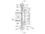
- the liquid feed pump 100 is a diaphragm pump including a pump body 110, check valves 126 and 127, a metal diaphragm 180, and an actuator 150 that drives the diaphragm 180.
- the pump body 110 includes an inlet-side internal flow path 122, an outlet-side internal flow path 124, and check valves 126 and 127 as flow paths through which the eluent flows.
- the pump body 110 can be made of, for example, metal or PEEK material.
- the check valve 126 is a check valve that allows only the flow of the eluent from the inflow port 121 (IN port) toward the inlet side internal flow path 122 and does not allow the flow in the opposite direction.
- the check valve 127 is a check valve that allows only the flow of the eluent in the direction from the outlet side internal flow path 124 to the discharge port 125 (OUT port) and does not allow the flow in the opposite direction.
- FIG. 1 illustration of the fastener which fastens the pump body 110 and the pump base 130 is abbreviate
- the pump body 110 has a cylindrical shape and has a truncated conical concave surface at the center position of one bottom surface thereof.
- the pump chamber 123 is formed as a space surrounded by the truncated conical concave surface and the diaphragm 180.
- the frustoconical concave surface has a flat bottom 115 which is a circular plane formed at the center thereof, a conical inclined surface 112 formed around the flat bottom 115, and the flat bottom 115 and the inclined surface. 112 and a doughnut-shaped curved surface 112r formed between them.
- the truncated conical concave surface is formed as a concave curved surface that is a concave curved surface in a direction to be fitted to a diaphragm driven in the ejection direction.
- openings of the inlet side internal flow path 122 and the outlet side internal flow path 124 are formed. These openings are arranged at positions facing each other across the plane bottom 115. Specifically, the inlet-side internal flow path 122 and the outlet-side internal flow path 124 are arranged in a vertical relationship with the center of the flat bottom portion 115 interposed therebetween.
- a suction side groove 113 extending upward in FIG. 3 toward the center of the truncated conical concave surface is formed continuously.
- a discharge-side groove 114 extending downward in FIG. 3 toward the center position of the truncated conical concave surface is formed continuously in the opening of the outlet-side internal flow path 124.
- the pump chamber 123 can sufficiently ensure the communication state between the inlet-side internal flow path 122 and the outlet-side internal flow path 124 even when the diaphragm 180 is displaced and close to the inclined surface 112. it can.
- the inlet side internal flow path 122 and the outlet side internal flow path 124 are also referred to as a suction passage and a discharge passage, respectively.
- the pump base 130 has a donut shape in which a cylinder hole 134 that is a cylindrical hole is disposed at the position of the central axis.
- the pump base 130 has frustoconical convex surfaces 132, 133, and 135 formed on one bottom surface thereof, and an opening 136 of the cylinder hole 134, and the conical concave surface 131 is formed on the other surface.
- an annular convex portion 131 p that forms the cylinder hole 134 is provided at the bottom of the concave surface 131.
- a sliding bearing 137b inserted from the annular convex portion 131p side is attached to the cylinder hole 134.
- the frustoconical convex surfaces 132, 133, and 135 have integral annular flat surfaces 132 and 133 that are surrounded by an inclined surface 135.
- the opening 136 of the cylinder hole 134 is concentrically provided with respect to the annular flat surfaces 132 and 133 (diaphragm receiving surfaces 133 described later). That is, the opening 136 is disposed at the center position of the annular planes 132 and 133. Further, the center of the opening 136 of the cylinder hole 134 is configured to align with the center of the concave surface in the axial direction of the cylinder hole 134 (left side in FIG. 2).
- the diaphragm 180 is sandwiched between the pump body 110 and the pump base 130.
- a seal pressure surface 111 which is an annular flat surface is formed.
- An inclined surface 116 is formed on the outer periphery of the outer edge of the seal pressure surface 111, and the seal pressure surface 111 is formed as an annular convex portion.
- the annular flat surfaces 132 and 133 of the pump base 130 have two regions of a seal receiving surface 132 which is a surface parallel to the seal pressing surface 111 and a diaphragm receiving surface 133 facing the inclined surface 112. It is a plane.
- the diaphragm 180 seals the pump chamber 123 from the outside by being sandwiched between the seal pressure surface 111 and the seal receiving surface 132.
- seal pressure surface 111 and the seal receiving surface 132 are also called seal portions.
- the role of the diaphragm receiving surface 133 will be described later.
- the pump chamber 123 is configured as a sealed space whose volume can be changed by the deformation of the diaphragm 180.
- the liquid feed pump 100 can function as a pump that periodically changes the volume in the pump chamber 123 and performs suction from the check valve 126 and discharge from the check valve 127.
- the pump base 130 and the pump body 110 are also called a pump housing.
- the diaphragm 180 can be deformed by driving the actuator 150 to change the volume of the pump chamber 123.
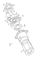
- the actuator 150 includes a drive unit 140 having a piston 144 that drives the diaphragm 180, and a pump base 130.
- the piston 144 is also called a reciprocating member.
- a driving force is applied to the piston 144 from the laminated piezoelectric actuator 141 via the steel ball 142 and the adjuster 143.
- the steel ball 142 is slidably sandwiched between a recess formed at the center position of the adjuster 143 attached to the center portion of the flange 144f and a recess formed at the center position of the laminated piezoelectric actuator 141.
- the urging spring 145 urges the piston 144 in the direction of reducing the driving force to the diaphragm 180 at the flange 144f.
- the laminated piezoelectric actuator 141 is housed in a cylindrical inner hole 149 formed inside the actuator housing 147, and is mounted on the actuator housing 147 with a position adjusting nut N1 and a fixing nut N2 via the piezoelectric actuator mounting portion 146. ing.
- the piston 144 is driven by manipulating the amount (length) of screwing between the male screw S formed on the outer periphery of the actuator housing 147 and the female screw formed on the inner periphery of the position adjusting nut N1.
- the relative positional relationship between the laminated piezoelectric actuator 141 and the pump base 130 in the direction can be adjusted.
- the fixing nut N2 functions as a double nut together with the position adjusting nut N1, and can fix the position of the piezoelectric actuator mounting portion 146 after the positional relationship is adjusted.
- FIG. 4 is an enlarged cross-sectional view showing the positional relationship between the piston 144 and the opening 136.
- the position of the piston 144 when not driven is indicated by a virtual line
- the position of the piston 144 when driven in the high pressure mode is indicated by a solid line.
- the position of the laminated piezoelectric actuator 141 is adjusted so that the top of the tip end surface 148 of the piston 144 is substantially at the same position as the opening 136 in the displacement direction of the piston 144.
- the driving voltage of the laminated piezoelectric actuator 141 is adjusted so that the peripheral portion 148e of the tip surface 148 of the piston 144 is located at the same position as the opening 136 in the same displacement direction. .
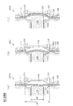
- FIG. 5 is a cross-sectional view showing a state of operation of the liquid feed pump 100 of the first embodiment.
- FIG. 5A shows the driving state in the high pressure operation.
- FIG. 5B shows the driving state in the low pressure operation.
- the high-pressure operation is an operating state in feeding the eluent during measurement.
- the operation at low pressure is an operating state in liquid feeding for pipe cleaning at the time of non-measurement.
- the diaphragm 180 In operation at high pressure, the diaphragm 180 is supported by the diaphragm receiving surface 133 and the piston 144. That is, the diaphragm 180 can flow the load received from the high-pressure eluent in the pump chamber 123 to the diaphragm receiving surface 133 and the piston 144. Specifically, a circular range having a diameter ⁇ B at the center position of the diaphragm 180 is supported by the piston 144, and an annular range excluding the circular range having the diameter ⁇ B from the circular range having the diameter ⁇ A is supported by the diaphragm receiving surface 133. ing.
- the deformation range (operation range) of the diaphragm 180 can be limited to a circular range having a diameter ⁇ B, so that the diaphragm 180 is substantially a small diaphragm having a circular range having a diameter ⁇ B. Will work. If the diaphragm is small, it can be appropriately driven by the laminated piezoelectric actuator 141 against the load applied to the diaphragm 180 even if the eluent has a high pressure.
- FIG. 6 is a cross-sectional view showing an operating state of the liquid feed pump 100a of the first comparative example.
- FIG. 6A shows a state when the liquid feeding pump 100a of the first comparative example is not driven.
- FIG. 6B shows the operating state of the liquid feeding pump 100a of the first comparative example when the pressure is high.
- FIG. 6C shows the operating state of the liquid feeding pump 100a of the first comparative example when the pressure is low.
- the first comparative example is a comparative example for easily explaining the effect of the diaphragm receiving surface 133.
- the liquid feed pump 100a of the first comparative example is not provided with the diaphragm receiving surface 133, and the diameter of the cylinder hole 134 is enlarged to the region of the diaphragm receiving surface 133, thereby forming the cylinder hole 134a. It is different from the liquid feed pump 100 of the embodiment. Since the liquid feed pump 100a of the first comparative example does not include the diaphragm receiving surface 133 of the first embodiment, it functions as a large diaphragm in low pressure operation.
- the liquid feed pump 100a of the first comparative example can function as a diaphragm pump having a relatively low discharge amount at a low pressure, as in the first embodiment.
- the diaphragm 180 is pressed against the piston 144a, and the bending 180k (the capacity of the pump chamber 123 is increased) is a deformation in a direction that reduces the capacity reduction of the pump chamber 123. It has been found by the present inventor that ejection cannot be performed efficiently. Further, the bending 180k causes damage as an excessive bending. Further, at the time of high pressure, the load applied from the diaphragm 180 to the piston 144a becomes larger than that in the first embodiment, and an excessive load is applied to the laminated piezoelectric actuator 141.
- FIG. 7 is a cross-sectional view showing the operating state of the liquid feed pump 100b of the second comparative example.
- FIG. 7A shows a state when the liquid feeding pump 100b of the second comparative example is not driven.
- FIG. 7B shows the operating state of the liquid feeding pump 100b of the second comparative example when the pressure is high.
- FIG.7 (c) has shown the operation state at the time of the low pressure of the liquid feeding pump 100b of a 2nd comparative example.
- the second comparative example is a comparative example for easily explaining the significance that the diaphragm receiving surface 133 of the first embodiment is provided in the same plane as the seal receiving surface 132 (or in an adjacent plane).
- the liquid feed pump 100b of the second comparative example is the same as that of the first embodiment in that the diaphragm receiving surface 133 is a diaphragm receiving surface 133a provided so as to be located in a direction away from the pump chamber 123 (left side in the drawing). Different from the liquid feed pump 100. On the other hand, the diameter of the piston 144 is the same as that of the liquid feed pump 100 of the first embodiment.
- FIG. 7C it can operate as a diaphragm pump that operates at a low pressure and a relatively large discharge amount as in the first embodiment and the first comparative example.
- the entire surface of the diaphragm 180 receives a load from the high-pressure eluent as in the first comparative example, so that the diaphragm 180 is placed around the piston 144.
- an unexpected bending 180k is generated, and the discharge is hindered, causing wear.
- an excessive load is applied to the laminated piezoelectric actuator 141 at the time of high pressure.
- the diaphragm receiving surface 133 of the first embodiment has a remarkable effect by forming an annular flat surface integrally with the seal receiving surface 132.
- the diaphragm receiving surface 133 does not necessarily need to form an annular flat surface that is continuous with the seal receiving surface 132 and may be disposed in the vicinity of the seal receiving surface 132 in the displacement direction of the piston 144.
- the diaphragm receiving surface 133 may be inclined from the seal receiving surface 132 side toward the opening 136 side toward the side close to the concave surface (the right side in FIG. 2).
- the diaphragm receiving surface 133 may be inclined from the seal receiving surface 132 side toward the opening 136 side toward the side away from the concave surface (left side in FIG. 2). Further, if the diaphragm receiving surface 133 and the seal receiving surface 132 are smoothly continuous, the deformation of the diaphragm 180 may be smooth even if it is not flat, for example, an integrated curved surface is formed. it can.
- FIG. 8 is a cross-sectional view showing a state of displacement (deformation) of the diaphragm 180 of the liquid delivery pump 100 of the first embodiment.
- FIG. 8A shows an operating state at high pressure.
- FIG. 8B shows an operation state at an intermediate pressure.
- FIG. 8C shows an operating state at low pressure.
- the operation states of FIG. 8A and FIG. 8C correspond to the operation states of FIG. 5A and FIG. 5B, respectively.
- the displacement (stroke) of the piston 144 is limited, so that the range in which the diaphragm 180 is displaced (also referred to as a deformation range or an operation range) is limited to a circular range having a diameter ⁇ B.
- the amount of displacement of the piston 144 is automatically limited as the internal pressure of the pump chamber 123 increases. For example, depending on the specifications of the laminated piezoelectric actuator 141, the control law is switched to that for high pressure, which is excessive. The load may not be applied to the diaphragm 180.
- the displacement amount (stroke) of the piston 144 is expanded, and the operating range of the diaphragm 180 is expanded to a circular range having a diameter ⁇ C.
- the operating range of the diaphragm 180 is expanded with a decrease in the pressure of the eluent, and the displacement amount (stroke) of the piston 144 is further expanded at a low pressure, and is expanded to the entire region, that is, a circular range having a diameter ⁇ A.
- the liquid feed pump 100 of the first embodiment can automatically change the operating range of the diaphragm 180 according to the discharge pressure of the eluent. Specifically, the operating range of the diaphragm 180 becomes narrower as the internal pressure of the pump chamber 123 increases, and becomes wider as the internal pressure of the pump chamber 123 decreases.
- the liquid feed pump 100 can be controlled by using, for example, a control system in which the measured value of the discharge flow rate is used as a feedback amount and the operation amount is an applied voltage to the laminated piezoelectric actuator 141.
- a control system in which the measured value of the discharge flow rate is used as a feedback amount and the operation amount is an applied voltage to the laminated piezoelectric actuator 141.
- the displacement amount of the piston 144 when the measured value of the discharge flow rate is small with respect to the target value, the displacement amount of the piston 144 is operated in an increasing direction, and when the measured value of the discharge flow rate is larger than the target value, the displacement of the piston 144 is performed. The amount is manipulated in the direction of reduction.
- the specific configuration of the control system of the embodiment will be described later.
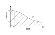
- FIG. 9 is a graph showing the relationship between the allowable displacement amount of the piston 144 and the discharge pressure of the liquid feed pump 100 according to the first embodiment.
- FIG. 10 is a graph showing the relationship between the allowable drive frequency of the piston 144 and the discharge flow rate (set flow rate) of the liquid delivery pump 100 of the first embodiment.
- curves C1 and C2 represent operational restrictions on the displacement and frequency of the piston 144, respectively. Specifically, for example, when the discharge pressure is the pressure P1, the displacement amount of the piston 144 is limited to the displacement ⁇ 1. On the other hand, when the discharge flow rate is the flow rate Q1, the drive frequency of the piston 144 is limited to the frequency f1. That is, the operation displacement of the piston 144 is limited to a range surrounded by the two curves C1 and C2.
- the liquid feed pump 100 has a preferable characteristic of automatically changing the operating range in accordance with the discharge pressure of the eluent.
- the present inventor has the possibility of damaging the diaphragm 180 due to excessive displacement of the diaphragm 180 (substantially displacement of the piston 144) depending on the specification setting of the laminated piezoelectric actuator 141 (for example, excessive driving force). I found it. Specifically, the present inventors have found that the diaphragm 180 is damaged around the piston 144 when the operation state of FIG. 8C is repeated due to an excessive driving force of the multilayer piezoelectric actuator 141 at high pressure. It was done.
- the present inventors have found that the influence of pulsation increases as the discharge flow rate decreases. This is because the decrease in the discharge flow rate increases the ratio of pulsation and the pulsation becomes apparent. Furthermore, in high performance liquid chromatography, measurement is performed during high pressure operation with a small discharge flow rate, so it is desirable to reduce pulsation. On the other hand, the present inventor has found that the drive frequency can be increased when the pump operation (the operation of the laminated piezoelectric actuator 141 or the operation of the check valve) is reduced due to a decrease in the discharge flow rate.
- FIG. 11 is a graph showing contents of switching of the driving frequency of the diaphragm in the liquid delivery pump 100 of the first embodiment.
- FIG. 11A and FIG. 11B show the discharge flow rate (flow rate) and the pulse voltage in the low pressure operation mode and the high pressure operation mode, respectively.
- a relatively large discharge flow rate Q1 is discharged by driving the diaphragm 180 at a relatively low drive frequency f1.
- the liquid feed pump 100 of the first embodiment can switch the drive frequency of the diaphragm 180 according to the discharge flow rate.
- the pulsation can be suppressed by increasing the driving frequency at the small discharge flow rate Q2 while maintaining the operating frequency range of the diaphragm at the large discharge flow rate Q1. Since the discharge flow rate Q2 at the time of high pressure operation is a flow rate used at the time of measurement, the reduction of pulsation has great significance.
- the driving frequency of the diaphragm is not necessarily operated according to switching between the low pressure operation mode and the high pressure operation mode, but may be operated according to a change in the set flow rate during high pressure operation, for example.
- the set flow rate is a discharge flow rate set by the user according to the measurement target, the purpose of measurement, and the like, and is a value that becomes a target value in a control system described later.
- the driving frequency of the diaphragm 180 is increased, not only can the pulsation be reduced, but also the discharge flow rate can be increased while maintaining the stroke of the diaphragm 180, so the range of the set flow rate of the liquid feed pump 100 during high pressure operation can be reduced. Can be enlarged. In other words, not only can the pulsation during measurement be further reduced to improve measurement accuracy, but it can also contribute to the expansion of the dynamic range of the discharge flow rate of the liquid feed pump 100 during high-pressure operation.
- FIG. 12 is a graph showing the drive voltage W1, the discharge flow rate C3, and the piston movement amount C4 of the liquid feed pump 100 of the first embodiment.
- the drive voltage W1 is a voltage applied to the laminated piezoelectric actuator 141, and is a rectangular wave.
- the liquid feeding pump 100 starts driving the piston 144 by the laminated piezoelectric actuator 141 in response to the rising of the driving voltage W1.
- the piston 144 starts to displace the diaphragm 180 and starts to reduce the volume of the pump chamber 123, so that the internal pressure of the pump chamber 123 increases.
- the check valve 127 is opened when the internal pressure of the pump chamber 123 exceeds the pressure of the discharge port 125 and starts discharging the chemical liquid.
- the discharge flow rate C3 is a flow rate supplied to a measurement device prepared by the user such as an injector or a column.
- the discharge flow rate C3 is a value measured by the flow rate sensor 50 downstream of the volume damper 80 and the orifice 51 described later.
- the discharge flow rate C3 is reduced in pulsation by the volume damper 80 and the orifice 51.
- the control circuit 10 operates the driver circuit 20 according to the measurement value of the flow rate sensor 50 with respect to the flow rate command signal, adjusts the voltage value of the drive voltage, and feedback for bringing the measurement value of the flow rate sensor 50 closer to the flow rate command signal. Take control.
- This feedback control is performed within a range of an allowable displacement amount (allowable drive voltage) and an allowable drive frequency (voltage pulse frequency) set in advance based on operation restrictions (see FIGS. 9 and 10).
- FIG. 15 is an explanatory diagram showing the contents of the measurement of the flow sensor 50 and the feedback thereof in the high-speed chromatography device 90 of the first embodiment.
- the control circuit 10 controls the flow rate by averaging and feeding back the discharge flow rate measured (sampled) by the flow rate sensor 50 at a plurality of measurement timings for each driving cycle of the reciprocating drive of the multilayer piezoelectric actuator 141 for each cycle. .
- the measurement error resulting from the flow volume (pulsation) which fluctuates periodically by the pump operation can be suppressed, and accurate feedback control can be realized.
- a measurement error due to pulsation occurs due to a measurement timing shift (phase difference) in each drive cycle.
- the high-speed chromatography apparatus 90 opens the waste liquid valve 71 and discharges the liquid into the waste liquid bottle 70 when introducing or replacing the eluent. At this time, the liquid feed pump 100 is required to discharge a large flow rate at a low pressure.
- FIG. 16 is a cross-sectional view showing a diaphragm 180a used in the liquid feed pump 100c of the second embodiment.
- the diaphragm 180a includes a first metal plate 181 and a second metal plate 182 made of nickel cobalt alloy, and an elastic adhesive layer 183 that forms an adhesive layer that bonds the first metal plate 181 and the second metal plate 182 to each other. It has a layer structure.
- the elastic adhesive layer 183 is a resin layer having elasticity in a direction in which the first metal plate 181 and the second metal plate 182 are shifted from each other in the in-plane direction.
- a one-pack type elastic adhesive mainly composed of a modified silicone resin or an epoxy-modified silicone resin, or a two-part type composed of, for example, a main agent (epoxy resin) and a curing agent (modified silicone resin).
- Elastic adhesives are available.
- FIG. 17 is a cross-sectional view showing the operating states of the diaphragm 180a of the second embodiment and the diaphragm 180b of the comparative example in comparison.
- FIG. 17A shows a state where the diaphragm 180a of the second embodiment is deformed.
- FIG. 17B shows a state in which the diaphragm 180b of the comparative example is deformed.
- the diaphragm 180b of the comparative example is a diaphragm in which the first metal plate 181 and the second metal plate 182 are superposed on each other, but does not have an adhesive layer as in the second embodiment.
- the first metal plate 181 and the second metal plate 182 having a thickness t are overlapped with each other, so that the pressure resistance is doubled.
- the pressure resistance depends on the tensile strength in the in-plane direction (spreading direction) of the first metal plate 181 and the like, so that the diaphragm 180a is substantially the same as a metal plate material having a single layer and twice the thickness. This is because it has pressure resistance.
- the diaphragm 180a of the second embodiment is different in that the first metal plate 181 and the second metal plate 182 are bonded to each other. Since the pressure resistance depends on the tensile strength in the in-plane direction (longitudinal direction) of the first metal plate 181 and the like, the pressure resistance can be improved by a factor of 2 regardless of the presence or absence of bonding.
- the diaphragm 180a can reduce the maximum strain of each of the first metal plate 181 and the second metal plate 182, durability can also be improved.
- the thickness of the elastic adhesive layer 183 is desirably 10 ⁇ m or less.
- the elastic adhesive layer 183 is deformed in the out-of-plane direction (thickness direction) of the diaphragm 180a due to the pressure of the pump chamber 123 and changes the volume of the pump chamber 123, which may make the discharge amount unstable. It is.
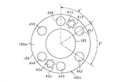
- FIG. 19 is a plan view showing the appearance of another example diaphragm 180c of the second embodiment.
- the diaphragm 180c includes a mounting plate 189.
- a portion of the mounting plate 189 that protrudes in the outer edge direction from the other metal plate 185 or the like is a mounting portion 189 a for mounting on the pump body 110.
- the mounting portion 189a is formed with a pair of key holes K1h and K2h and through holes dh1 to dh6 through which each of the six bolts B1 to B6 passes.
- the six bolts B1 to B6 are also called fastening members.
- the pump body 110 and the actuator 150 are also called a first member and a second member, respectively.
- the through holes dh1 to dh6 are annularly arranged with an uneven pitch. Specifically, the angle ⁇ between the through hole dh1 and the through hole dh6 is set to an angle different from the angle ⁇ between the through hole dh1 and the through hole dh2. As a result, the keys K1 and K2 are attached to the key holes K1h and K2h, respectively, and can be prevented from being attached in reverse.
- the through holes dh1 to dh6 are not necessarily formed side by side in a ring shape.
- the shape formed by connecting the center positions of the through holes dh1 to dh6 (in this case, a hexagon) is an asymmetric shape with respect to a line segment in any direction within the surface of the diaphragm 180c. Good. Thereby, the erroneous mounting
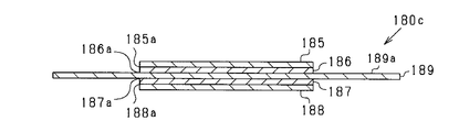
- FIG. 20 is a cross-sectional view showing a stacked state of another example diaphragm 180c of the second embodiment.
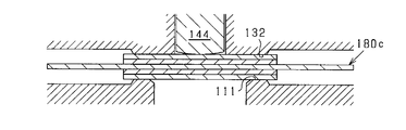
- FIG. 21 is a cross-sectional view showing a mounting state of a diaphragm 180c of another example of the second embodiment.
- Diaphragm 180c is formed by laminating, for example, four metal plates 185 to 188 made of nickel cobalt alloy and one mounting plate 189 made of stainless steel (eg SUS304 or SUS316).
- metal plates 186 and 187 are attached to both sides of a mounting plate material 189, which is a stainless steel metal plate, via elastic adhesive layers 186a and 187a, respectively. Further, each of the metal plates 186 and 187 is elastic. Metal plates 185 and 188 are attached via adhesive layers 185a and 188a. Thus, in this embodiment, four metal plates 185 to 188 of the same number of nickel cobalt alloys are mounted on each of both surfaces of the stainless steel mounting plate 189.
- a silicone film of several ⁇ m can be used for the elastic adhesive layers 185a, 186a, 187a and 188a.
- the metal plate 188 is a surface facing the pump chamber 123, it is preferably polished.
- Nickel-cobalt alloy is a material suitable for a metal diaphragm in that it has high elasticity, strength, corrosion resistance, heat resistance and constant elasticity, is non-magnetic and has excellent durability.
- stainless steel is rich in workability and has characteristics such as corrosion resistance, toughness, and ductility.
- the good workability of stainless steel which is the material of the mounting plate 189, can facilitate the process of forming the key holes K1h and K2h and the through holes dh1 to dh6.
- the mounting plate 189 is used for assembling the diaphragm 180c when the liquid feed pump 100a is disassembled and cleaned.
- the four metal plates 185 to 188 made of nickel cobalt alloy are members for functioning as diaphragms. Between the seal pressing surface 111 and the seal receiving surface 132, four metal plates 185 to 188 made of nickel cobalt alloy and a stainless plate 189 for mounting are sandwiched.
- the multilayer diaphragm of the present embodiment can freely set the number of stacked layers from the viewpoint of the pressure resistance and operability of the diaphragm.
- the liquid feed pump of this embodiment can realize a long life without generation of particles.
- the liquid feed pump of this embodiment can realize a high pressure micro flow and a low pressure large flow rate (wide dynamic range).
- the operating range (deformation range) of the diaphragm can be changed smoothly from high pressure to low pressure. it can.
- the opening of the cylinder hole is formed concentrically with the diaphragm receiving surface, so that the piston is positioned at the substantially central portion of the area surrounded by the seal pressing surface and the seal receiving surface in the diaphragm. It comes to press.
- the liquid feed pump of the present embodiment is configured such that the center of the opening of the cylinder hole is aligned with the center of the concave surface in the axial direction of the cylinder hole. Accordingly, when the diaphragm is deformed, the volume of the central portion of the pump chamber changes, so that the pressure in the pump chamber changes in a well-balanced manner and the eluent can be sent smoothly.
- the amount of displacement of the piezoelectric actuator is limited according to the discharge pressure, so that the diaphragm can be prevented from being damaged due to excessive displacement of the piezoelectric actuator at high pressure.
- the multilayer diaphragm of the present embodiment can achieve both high pressure resistance and flexibility.
- the multi-layer diaphragm according to the present embodiment realizes suppression of erroneous mounting and improves maintainability.
- the multilayer diaphragm of this embodiment can make calibration unnecessary after disassembly and cleaning unnecessary or simplified.
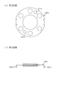
- FIG. 22 is an external view showing the configuration of the diaphragm 180d of the first modification and the pump body 110a.
- a third key hole K3h is formed in addition to the key holes K1h and K2h. Accordingly, it is possible to prevent a situation in which the diaphragm 180d rotates 180 degrees around its central axis and the keys K1 and K2 are attached to the wrong key holes K1h and K2h (reverse key holes). That is, it is possible to prevent the key K1 and the key K2 from being attached to the key hole K2h and the key hole K1h, respectively.
- the third key hole K3h is formed at a position deviating from the perpendicular bisector of the line connecting the center positions of the key holes K1h and K2h.
- the key holes K1h, K2h, K3h are formed in a ring at an unequal pitch on the diaphragm 180d. As a result, it is possible to prevent a situation in which the diaphragm 180d is turned over and rotated 180 degrees to be attached to the reverse key holes K2h and K1h.
- the diaphragm 180d of the first modified example is provided with a key and a key hole for various erroneous mountings such as erroneous mounting in a state rotated 180 degrees and erroneous mounting in a state rotated 180 degrees in an inverted state. It can prevent by providing.
- the keys K1, K2, K3 and the key holes K1h, K2h, K3h are also called positioning portions.
- the keys K1, K2, and K3 are also called positioning convex portions.
- the key holes K1h, K2h, K3h are also called positioning holes. Note that the key holes K1h, K2h, K3h are not necessarily formed in a ring.
- the shape formed by connecting the center positions of the key holes K1h, K2h, and K3h may be asymmetric with respect to the line segment in any direction in the plane of the diaphragm 180d. That's fine. Thereby, erroneous mounting of the diaphragm 180d can be suppressed.
- the diaphragm 180c is prevented from falling off from the pump body 110 by the urging portions K1s and K2s equipped in the key holes K1h and K2h.
- an urging portion for preventing dropout may be provided in addition to the key holes K1h and K2h.
- FIG. 23 is a plan view and a cross-sectional view showing the configuration of the diaphragm 180e of the second modified example.
- the diaphragm 180e includes a pair of temporary fixing collars 180s1 and 180s2.
- the temporarily fixing collars 180s1 and 180s2 can generate an urging force in a direction in which the pump body 110a is sandwiched (a direction in which a mutual interval is reduced). This prevents the diaphragm 180e from falling off the pump body 110a and facilitates assembly.
- the diaphragm 180e may be prevented from falling off by urging a part of the pump body 110 so that the reaction force is canceled out.
- the diaphragm receiving surface forms the same plane as the seal receiving surface, but it is not always necessary to form the same plane. However, if the same plane is formed, the operation range (deformation range) of the diaphragm can be smoothly changed from high pressure to low pressure.
- the diaphragm receiving surface 133 may be configured so that the contact area, which is the area of the surface that contacts the diaphragm 180, changes according to the internal pressure of the pump chamber 123.
- the seal receiving surface is a flat surface, but may be a curved surface.
- the seal receiving surface is a flat surface, it is possible to avoid a situation where the diaphragm is excessively damaged by a load (sealing load) applied to the diaphragm for sealing the pump chamber.
- a load sealing load
- the torque management of the bolts B1 to B6 by the user can be facilitated when the diaphragm is remounted.
- the piston has a curved surface with a convex contact surface with the diaphragm, but may be a flat surface.
- the contact surface with the diaphragm is a convex curved surface
- the region contacting the piston with the convex curved surface is deformed while supporting the diaphragm around the opening 136 of the cylinder hole 134 with the diaphragm receiving surface. be able to.
- the diaphragm is deformed while expanding the deformation range in accordance with the displacement amount of the piston, it is possible to realize a precise discharge amount operation at a high pressure.
- the convex curved surface may be a spherical shape that can be easily processed, for example.
- the suction port and the discharge port are disposed at opposite positions, but other layouts may be used. However, if the suction port and the discharge port are arranged opposite to each other, for example, a liquid feed pump is installed so that the suction port is on the lower side and the discharge port is on the upper side in the vertical direction, thereby eliminating the liquid pool. It is possible to improve liquid substitutability and bubble removal.
- the diaphragm is driven by the piezoelectric actuator, but other driving methods may be used.
- the diaphragm when driven by a piezoelectric actuator, by driving the diaphragm at a high frequency, it is possible to secure a discharge amount even with a small displacement of the diaphragm and to reduce pulsation.
- the entire diaphragm receiving surface is in contact with the diaphragm when not driven.
- at least a part of the diaphragm receiving surface may be separated from the diaphragm, or may be configured to be in such a state by permanent deformation during operation.
- the diaphragm receiving surface only needs to be configured to support the diaphragm when the internal pressure of the pump chamber increases and reduce the load applied to the piston.
- the diaphragm receiving surface shares the load obtained by multiplying the area of the surface where the diaphragm and the diaphragm receiving surface abut with the internal pressure of the pump chamber, thereby reducing the load applied to the piston. can do.
- the area of the surface where the diaphragm and the diaphragm receiving surface abut is also referred to as the abutting area.
- the diaphragm is not connected to the piston, and the diaphragm is deformed by pressing the diaphragm with the piston.
- the diaphragm and the piston may be connected.
- the multi-layer diaphragm is used for a liquid feed pump, but it can also be used for a flow control valve, for example.
- Multi-layer diaphragms can be widely used in fluidic devices that generally use diaphragms.
Landscapes
- Engineering & Computer Science (AREA)
- Mechanical Engineering (AREA)
- General Engineering & Computer Science (AREA)
- Reciprocating Pumps (AREA)
Abstract
Priority Applications (4)
| Application Number | Priority Date | Filing Date | Title |
|---|---|---|---|
| JP2012543401A JP5191618B2 (ja) | 2011-04-27 | 2012-04-04 | 送液ポンプ及び流量制御装置 |
| EP12776156.7A EP2653724B1 (fr) | 2011-04-27 | 2012-04-04 | Pompe d'alimentation en liquide et dispositif de régulation du débit |
| CN201280002865.0A CN103097730B (zh) | 2011-04-27 | 2012-04-04 | 液体馈送泵及流量控制装置 |
| US14/012,820 US8888471B2 (en) | 2011-04-27 | 2013-08-28 | Liquid feed pump and flow control device |
Applications Claiming Priority (2)
| Application Number | Priority Date | Filing Date | Title |
|---|---|---|---|
| JP2011100011 | 2011-04-27 | ||
| JP2011-100011 | 2011-04-27 |
Related Child Applications (1)
| Application Number | Title | Priority Date | Filing Date |
|---|---|---|---|
| US14/012,820 Continuation US8888471B2 (en) | 2011-04-27 | 2013-08-28 | Liquid feed pump and flow control device |
Publications (1)
| Publication Number | Publication Date |
|---|---|
| WO2012147476A1 true WO2012147476A1 (fr) | 2012-11-01 |
Family
ID=47072000
Family Applications (1)
| Application Number | Title | Priority Date | Filing Date |
|---|---|---|---|
| PCT/JP2012/059254 WO2012147476A1 (fr) | 2011-04-27 | 2012-04-04 | Pompe d'alimentation en liquide et dispositif de régulation du débit |
Country Status (5)
| Country | Link |
|---|---|
| US (1) | US8888471B2 (fr) |
| EP (1) | EP2653724B1 (fr) |
| JP (1) | JP5191618B2 (fr) |
| CN (1) | CN103097730B (fr) |
| WO (1) | WO2012147476A1 (fr) |
Cited By (2)
| Publication number | Priority date | Publication date | Assignee | Title |
|---|---|---|---|---|
| KR101809992B1 (ko) * | 2016-05-11 | 2017-12-18 | 안성룡 | 다이아프램 방식 정량 펌프 |
| JP2019044619A (ja) * | 2017-08-30 | 2019-03-22 | 株式会社Screenホールディングス | ポンプ装置、処理液供給装置および基板処理装置 |
Families Citing this family (5)
| Publication number | Priority date | Publication date | Assignee | Title |
|---|---|---|---|---|
| ITUB20153349A1 (it) * | 2015-09-02 | 2017-03-02 | Ip Cleaning S P A | Macchina di trattamento di superfici |
| CN110566432A (zh) * | 2018-06-05 | 2019-12-13 | 上海渔霁生物技术有限公司 | 一种液相色谱仪用轴向多柱塞无脉冲高压输液泵 |
| CN109045415B (zh) * | 2018-08-29 | 2024-05-07 | 广州大学 | 一种微量注射泵 |
| JP6895493B2 (ja) * | 2019-08-27 | 2021-06-30 | 株式会社タクミナ | ダイヤフラムポンプ |
| US11486379B2 (en) * | 2019-09-12 | 2022-11-01 | Cal Poly Corporation | Self-regulating bimetallic diaphragm pump |
Citations (9)
| Publication number | Priority date | Publication date | Assignee | Title |
|---|---|---|---|---|
| JPS6030489A (ja) * | 1983-07-30 | 1985-02-16 | Iwaki:Kk | ダイヤフラム・ポンプのダイヤフラム |
| JPS62159778A (ja) | 1986-01-08 | 1987-07-15 | Fuji Electric Co Ltd | ダイアフラム式ポンプ |
| JPH062664A (ja) | 1992-06-22 | 1994-01-11 | Nippon Soken Inc | ダイアフラム式ポンプ |
| JPH062663A (ja) | 1992-06-15 | 1994-01-11 | Toyota Motor Corp | ダイヤフラム式ポンプ |
| JPH07174075A (ja) * | 1993-12-20 | 1995-07-11 | Teikoku Denki Seisakusho:Kk | 液圧駆動式膜ポンプ |
| JP2003207494A (ja) | 2002-01-11 | 2003-07-25 | Sumitomo Chem Co Ltd | クロマトグラフ装置用分流装置 |
| JP2006029314A (ja) | 2004-05-13 | 2006-02-02 | Noiberuku Kk | ダイアフラムポンプおよび電子部品の製造装置 |
| JP2006118397A (ja) | 2004-10-20 | 2006-05-11 | Matsushita Electric Works Ltd | 圧電ダイヤフラムポンプ |
| JP2007292011A (ja) | 2006-04-27 | 2007-11-08 | Shimadzu Corp | 送液ポンプ及びその送液ポンプを用いた液体クロマトグラフ |
Family Cites Families (10)
| Publication number | Priority date | Publication date | Assignee | Title |
|---|---|---|---|---|
| DE3446914A1 (de) * | 1984-12-21 | 1986-07-03 | Ott Kg Lewa | Membranpumpe mit hydaulisch angetriebener rollmembran |
| DE4327969C2 (de) * | 1993-08-19 | 1997-07-03 | Ott Kg Lewa | Hydraulisch angetriebene Membranpumpe |
| JP2001088279A (ja) * | 1999-09-20 | 2001-04-03 | Fuji Photo Film Co Ltd | 画像形成方法および装置 |
| DE10012902B4 (de) * | 2000-03-16 | 2004-02-05 | Lewa Herbert Ott Gmbh + Co. | Atmungsfreie Membraneinspannung |
| US7238164B2 (en) * | 2002-07-19 | 2007-07-03 | Baxter International Inc. | Systems, methods and apparatuses for pumping cassette-based therapies |
| US7287965B2 (en) * | 2004-04-02 | 2007-10-30 | Adaptiv Energy Llc | Piezoelectric devices and methods and circuits for driving same |
| JP5350272B2 (ja) * | 2007-02-02 | 2013-11-27 | ソシエテ ビック | 水素ガス発生器 |
| US20090112155A1 (en) * | 2007-10-30 | 2009-04-30 | Lifescan, Inc. | Micro Diaphragm Pump |
| US8057198B2 (en) * | 2007-12-05 | 2011-11-15 | Ford Global Technologies, Llc | Variable displacement piezo-electric pumps |
| US8267675B2 (en) * | 2008-06-16 | 2012-09-18 | GM Global Technology Operations LLC | High flow piezoelectric pump |
-
2012
- 2012-04-04 WO PCT/JP2012/059254 patent/WO2012147476A1/fr active Application Filing
- 2012-04-04 JP JP2012543401A patent/JP5191618B2/ja active Active
- 2012-04-04 EP EP12776156.7A patent/EP2653724B1/fr active Active
- 2012-04-04 CN CN201280002865.0A patent/CN103097730B/zh active Active
-
2013
- 2013-08-28 US US14/012,820 patent/US8888471B2/en active Active
Patent Citations (9)
| Publication number | Priority date | Publication date | Assignee | Title |
|---|---|---|---|---|
| JPS6030489A (ja) * | 1983-07-30 | 1985-02-16 | Iwaki:Kk | ダイヤフラム・ポンプのダイヤフラム |
| JPS62159778A (ja) | 1986-01-08 | 1987-07-15 | Fuji Electric Co Ltd | ダイアフラム式ポンプ |
| JPH062663A (ja) | 1992-06-15 | 1994-01-11 | Toyota Motor Corp | ダイヤフラム式ポンプ |
| JPH062664A (ja) | 1992-06-22 | 1994-01-11 | Nippon Soken Inc | ダイアフラム式ポンプ |
| JPH07174075A (ja) * | 1993-12-20 | 1995-07-11 | Teikoku Denki Seisakusho:Kk | 液圧駆動式膜ポンプ |
| JP2003207494A (ja) | 2002-01-11 | 2003-07-25 | Sumitomo Chem Co Ltd | クロマトグラフ装置用分流装置 |
| JP2006029314A (ja) | 2004-05-13 | 2006-02-02 | Noiberuku Kk | ダイアフラムポンプおよび電子部品の製造装置 |
| JP2006118397A (ja) | 2004-10-20 | 2006-05-11 | Matsushita Electric Works Ltd | 圧電ダイヤフラムポンプ |
| JP2007292011A (ja) | 2006-04-27 | 2007-11-08 | Shimadzu Corp | 送液ポンプ及びその送液ポンプを用いた液体クロマトグラフ |
Non-Patent Citations (1)
| Title |
|---|
| See also references of EP2653724A4 * |
Cited By (2)
| Publication number | Priority date | Publication date | Assignee | Title |
|---|---|---|---|---|
| KR101809992B1 (ko) * | 2016-05-11 | 2017-12-18 | 안성룡 | 다이아프램 방식 정량 펌프 |
| JP2019044619A (ja) * | 2017-08-30 | 2019-03-22 | 株式会社Screenホールディングス | ポンプ装置、処理液供給装置および基板処理装置 |
Also Published As
| Publication number | Publication date |
|---|---|
| CN103097730A (zh) | 2013-05-08 |
| JPWO2012147476A1 (ja) | 2014-07-28 |
| EP2653724B1 (fr) | 2015-09-23 |
| JP5191618B2 (ja) | 2013-05-08 |
| US8888471B2 (en) | 2014-11-18 |
| US20130343909A1 (en) | 2013-12-26 |
| EP2653724A1 (fr) | 2013-10-23 |
| CN103097730B (zh) | 2014-11-26 |
| EP2653724A4 (fr) | 2014-06-18 |
Similar Documents
| Publication | Publication Date | Title |
|---|---|---|
| JP5189227B2 (ja) | 複層ダイアフラム | |
| JP5191618B2 (ja) | 送液ポンプ及び流量制御装置 | |
| US20040136843A1 (en) | Diaphragm pump | |
| EP2107246B1 (fr) | Dispositif de transport de liquides avec une multiplicité de structures d'actionnement à double chambre | |
| CA2654688C (fr) | Pompe piezoelectrique | |
| US20040109769A1 (en) | Diaphragm pump | |
| US9217426B2 (en) | Pump, pump arrangement and pump module | |
| US20100290935A1 (en) | Pump arrangement comprising a safety valve | |
| KR20140074308A (ko) | 마이크로다이어프램 펌프 | |
| US9421545B2 (en) | Spring-less multi-position micro-fluidic valve assembly | |
| US20130068325A1 (en) | Valve, layer structure comprising a first and a second valve, micropump and method of producing a valve | |
| JP2003003952A (ja) | 流体吐出装置 | |
| JP2018123796A (ja) | マイクロダイヤフラムポンプ | |
| JP2014051950A (ja) | ベローズポンプ | |
| JP4994126B2 (ja) | 圧電駆動装置および液体吐出装置 | |
| CN106357151B (zh) | 一种大变形比片式压电驱动器结构 | |
| JP5221993B2 (ja) | マイクロバルブ及びマイクロポンプ | |
| US7686595B1 (en) | Diaphragm pump | |
| US8182246B1 (en) | High pressure open discharge pump system | |
| JP2005273865A (ja) | 弁とそれを用いた送液ポンプ | |
| US20220048063A1 (en) | Plural material dispensing system | |
| JP5371171B2 (ja) | ダイヤフラムポンプ | |
| JPH05195958A (ja) | 圧電ポンプ | |
| JPH04194380A (ja) | 液送ポンプ | |
| WO2001001024A1 (fr) | Structure de clapet anti-retour et micropompe utilisant ladite structure |
Legal Events
| Date | Code | Title | Description |
|---|---|---|---|
| WWE | Wipo information: entry into national phase |
Ref document number: 201280002865.0 Country of ref document: CN |
|
| ENP | Entry into the national phase |
Ref document number: 2012543401 Country of ref document: JP Kind code of ref document: A |
|
| 121 | Ep: the epo has been informed by wipo that ep was designated in this application |
Ref document number: 12776156 Country of ref document: EP Kind code of ref document: A1 |
|
| WWE | Wipo information: entry into national phase |
Ref document number: 2012776156 Country of ref document: EP |
|
| NENP | Non-entry into the national phase |
Ref country code: DE |