WO2012144110A1 - 画像表示シート及び画像表示体 - Google Patents
画像表示シート及び画像表示体 Download PDFInfo
- Publication number
- WO2012144110A1 WO2012144110A1 PCT/JP2011/079308 JP2011079308W WO2012144110A1 WO 2012144110 A1 WO2012144110 A1 WO 2012144110A1 JP 2011079308 W JP2011079308 W JP 2011079308W WO 2012144110 A1 WO2012144110 A1 WO 2012144110A1
- Authority
- WO
- WIPO (PCT)
- Prior art keywords
- image
- virtual image
- plano
- sheet
- virtual
- Prior art date
Links
Images


Classifications
-
- G—PHYSICS
- G02—OPTICS
- G02B—OPTICAL ELEMENTS, SYSTEMS OR APPARATUS
- G02B3/00—Simple or compound lenses
- G02B3/0006—Arrays
- G02B3/0037—Arrays characterized by the distribution or form of lenses
- G02B3/005—Arrays characterized by the distribution or form of lenses arranged along a single direction only, e.g. lenticular sheets
-
- B—PERFORMING OPERATIONS; TRANSPORTING
- B41—PRINTING; LINING MACHINES; TYPEWRITERS; STAMPS
- B41M—PRINTING, DUPLICATING, MARKING, OR COPYING PROCESSES; COLOUR PRINTING
- B41M3/00—Printing processes to produce particular kinds of printed work, e.g. patterns
- B41M3/14—Security printing
- B41M3/148—Transitory images, i.e. images only visible from certain viewing angles
-
- B—PERFORMING OPERATIONS; TRANSPORTING
- B44—DECORATIVE ARTS
- B44F—SPECIAL DESIGNS OR PICTURES
- B44F1/00—Designs or pictures characterised by special or unusual light effects
- B44F1/08—Designs or pictures characterised by special or unusual light effects characterised by colour effects
- B44F1/10—Changing, amusing, or secret pictures
-
- G—PHYSICS
- G02—OPTICS
- G02B—OPTICAL ELEMENTS, SYSTEMS OR APPARATUS
- G02B3/00—Simple or compound lenses
- G02B3/0006—Arrays
- G02B3/0037—Arrays characterized by the distribution or form of lenses
- G02B3/0056—Arrays characterized by the distribution or form of lenses arranged along two different directions in a plane, e.g. honeycomb arrangement of lenses
-
- G—PHYSICS
- G02—OPTICS
- G02B—OPTICAL ELEMENTS, SYSTEMS OR APPARATUS
- G02B30/00—Optical systems or apparatus for producing three-dimensional [3D] effects, e.g. stereoscopic images
- G02B30/20—Optical systems or apparatus for producing three-dimensional [3D] effects, e.g. stereoscopic images by providing first and second parallax images to an observer's left and right eyes
- G02B30/26—Optical systems or apparatus for producing three-dimensional [3D] effects, e.g. stereoscopic images by providing first and second parallax images to an observer's left and right eyes of the autostereoscopic type
- G02B30/27—Optical systems or apparatus for producing three-dimensional [3D] effects, e.g. stereoscopic images by providing first and second parallax images to an observer's left and right eyes of the autostereoscopic type involving lenticular arrays
- G02B30/29—Optical systems or apparatus for producing three-dimensional [3D] effects, e.g. stereoscopic images by providing first and second parallax images to an observer's left and right eyes of the autostereoscopic type involving lenticular arrays characterised by the geometry of the lenticular array, e.g. slanted arrays, irregular arrays or arrays of varying shape or size
-
- G—PHYSICS
- G03—PHOTOGRAPHY; CINEMATOGRAPHY; ANALOGOUS TECHNIQUES USING WAVES OTHER THAN OPTICAL WAVES; ELECTROGRAPHY; HOLOGRAPHY
- G03B—APPARATUS OR ARRANGEMENTS FOR TAKING PHOTOGRAPHS OR FOR PROJECTING OR VIEWING THEM; APPARATUS OR ARRANGEMENTS EMPLOYING ANALOGOUS TECHNIQUES USING WAVES OTHER THAN OPTICAL WAVES; ACCESSORIES THEREFOR
- G03B25/00—Viewers, other than projection viewers, giving motion-picture effects by persistence of vision, e.g. zoetrope
- G03B25/02—Viewers, other than projection viewers, giving motion-picture effects by persistence of vision, e.g. zoetrope with interposed lenticular or line screen
-
- G—PHYSICS
- G03—PHOTOGRAPHY; CINEMATOGRAPHY; ANALOGOUS TECHNIQUES USING WAVES OTHER THAN OPTICAL WAVES; ELECTROGRAPHY; HOLOGRAPHY
- G03B—APPARATUS OR ARRANGEMENTS FOR TAKING PHOTOGRAPHS OR FOR PROJECTING OR VIEWING THEM; APPARATUS OR ARRANGEMENTS EMPLOYING ANALOGOUS TECHNIQUES USING WAVES OTHER THAN OPTICAL WAVES; ACCESSORIES THEREFOR
- G03B35/00—Stereoscopic photography
- G03B35/18—Stereoscopic photography by simultaneous viewing
- G03B35/24—Stereoscopic photography by simultaneous viewing using apertured or refractive resolving means on screens or between screen and eye
-
- G—PHYSICS
- G02—OPTICS
- G02B—OPTICAL ELEMENTS, SYSTEMS OR APPARATUS
- G02B3/00—Simple or compound lenses
- G02B3/0006—Arrays
-
- G—PHYSICS
- G02—OPTICS
- G02B—OPTICAL ELEMENTS, SYSTEMS OR APPARATUS
- G02B3/00—Simple or compound lenses
- G02B3/0006—Arrays
- G02B3/0037—Arrays characterized by the distribution or form of lenses
- G02B3/0043—Inhomogeneous or irregular arrays, e.g. varying shape, size, height
Definitions
- the present invention relates to an image display sheet, and more particularly to an image display sheet capable of observing a virtual lens accompanied by a cylindrical lens or a plano-convex lens and movement, or movement and deformation, and an image display body using the image display sheet.
- the image display sheet includes a lenticular sheet configured by an array of a plurality of cylindrical lenses and an image forming layer.
- FIG. 26A and FIG. 26B are explanatory diagrams of a conventionally known image display sheet.
- FIG. 26A is an explanatory diagram showing the basic characteristics of the lenticular
- FIG. 26B is a schematic explanatory diagram showing the basic principle of the lenticular.
- An image forming layer 5003 is arranged on the surface opposite to the convex surface of the cylindrical lens 5002 constituting the lenticular sheet 5001 so that the image can be observed pseudo-dynamically from the lens side.
- the stereoscopic image or the image changes the viewing angle so that the image moves. You can observe the changing image.
- FIG. 1 is an explanatory diagram showing the basic characteristics of the lenticular
- FIG. 26B is a schematic explanatory diagram showing the basic principle of the lenticular.
- An image forming layer 5003 is arranged on the surface opposite to the convex surface of the cylindrical lens 5002 constituting the lenticular sheet 5001 so that the image can be observed pseudo-dynamically from the lens side.
- FIG. 27 is an explanatory diagram of a conventionally known image display sheet 5009.
- A is a cross-sectional explanatory view of a conventionally known image display sheet 5009
- B is a plan view of the image forming layer 5003.
- An image formed by dividing a plurality of original images A, B, C, and D into stripes is formed on an image forming layer 5003 formed on the image forming medium 5008.
- FIG. 27 shows an example in which a right-eye image 5004 and a left-eye image 5005 are divided with a predetermined width for each lens.
- the viewing angle is changed so that the A image can be seen at a certain position, the B image can be seen at a certain position, the C image can be seen at a certain position, and the D image can be seen at a certain position. It seems to move the image.
- Patent Document 1 when a plurality of original images are divided into stripes to form a single image so that different patterns can be seen depending on the viewing angle, the boundary between the pitches of the convex lens and the division boundary of the image are matched.
- Patent Document 2 discloses a technique for observing a pseudo variable image by dividing a left-eye image and a right-eye image into strip-shaped sections having a predetermined width for each lens and arranging them in an interlaced manner. Yes.
- An object of the present invention is to provide an image display sheet or the like that can realize a smooth pseudo moving image and can be observed with a reduced sense of incongruity in view of such problems and the like.
- the image display sheet of the present invention is configured by laminating a lenticular sheet constituted by an array of a plurality of cylindrical lenses and an image forming layer, and is arranged on the image forming layer from the side having the convex shape of the cylindrical lens of the lenticular sheet.
- An image display sheet configured to be capable of observing a formed image as a virtual image with movement or movement and deformation, and a plurality of images for displaying the virtual image by acting with the cylindrical lens on the image forming layer
- the virtual image observation image is repeatedly formed so as to substantially correspond to each of the cylindrical lenses, and the arrangement pitch length of the cylindrical lenses and the pitch length of the virtual image observation image repeatedly formed on the image forming layer Difference of the cylindrical lens arrangement pitch or the virtual image observation image.
- the relative switch length in the range of 0% to 10%.
- the image display sheet of the present invention is configured by laminating a plano-convex lens sheet composed of an array of a plurality of plano-convex lenses and an image forming layer, and forms the image from the side of the plano-convex lens sheet having the convex shape of the plano-convex lens.
- An image display sheet configured to be capable of observing an image formed on a layer as a virtual image with movement or movement and deformation, and for causing the image formation layer to display the virtual image by acting with the plano-convex lens.
- a plurality of virtual image observation images are repeatedly formed so as to substantially correspond to each of the plano-convex lenses, and the arrangement pitch length of the plano-convex lenses in the horizontal direction and the virtual image observation repeatedly formed on the image forming layer
- the horizontal pitch length of the image for the image is different, and the difference between the pitch lengths is the horizontal arrangement pitch length of the plano-convex lenses or the horizontal pitch length of the virtual image observation image.
- the difference between the vertical arrangement pitch length of the plano-convex lens and the vertical pitch length of the virtual image observation image repeatedly formed on the image forming layer is 10% or less.
- the vertical array pitch length or the vertical pitch length of the virtual image observation image is in the range of 0% to 10%.
- the plurality of virtual image observation images are configured by a virtual image observation image group including a predetermined number of virtual image observation images, and other virtual image observations except for a virtual image observation image near the center of the virtual image observation image group
- the image for use may have a notch on the side of the virtual image observation image near the center, and the notch may be configured to increase as the distance from the virtual image observation image near the center increases.
- the plurality of virtual image observation images have a still virtual image observation image group including a predetermined number of still virtual image observation images at an end of the virtual image observation image group, and the still virtual image observation image has an extension unit.
- the still virtual image observation images at least one of the still virtual image observation images located on the end side of the virtual image observation image group is perpendicular to the direction in which the virtual image observation images are arranged. You may comprise so that it may have a notch part in both ends.
- the plurality of virtual image observation images include a still virtual image observation image group including a predetermined number of still virtual image observation images at an end of the virtual image observation image group, and the still virtual image observation image includes the still virtual image observation image.
- At least one or more of the still virtual image observation images located on the end side of the virtual image observation image group of the still virtual image observation images, having an extension on the virtual image observation image side that is not an observation image May be configured to have notches at both ends in the direction perpendicular to the direction in which the virtual image observation images are arranged.
- the virtual image may be configured to be observable as the three-dimensional virtual image by floating above the lenticular sheet or the plano-convex lens sheet or sinking below the lenticular sheet or the plano-convex lens sheet.
- the image forming layer is another image different from the virtual image observation image, and is a stereoscopic image, a changing image, or an animation image for displaying the image to be observed by acting with the cylindrical lens or the plano-convex lens.
- a single image or a plurality of other images formed by a combination thereof, and one or a plurality of virtual image display units that display the virtual image based on the cylindrical lens or the plano-convex lens and the virtual image observation image, and the cylindrical You may comprise so that it may have a 1 or several to-be-observed image display part which displays the to-be-observed image based on a lens or the said plano-convex lens, and said other image.
- the image forming layer may be provided on the surface of the lenticular sheet opposite to the surface having the convex shape of the cylindrical lens or the surface of the plano-convex lens sheet opposite to the surface having the convex shape of the plano-convex lens. .
- An image forming medium having the image forming layer is provided, and the surface of the lenticular sheet opposite to the surface having the convex shape of the cylindrical lens, or the surface of the plano-convex lens sheet opposite to the surface having the convex shape of the plano-convex lens And a surface having the image forming layer of the image forming medium may be laminated.
- the virtual image observation image may be configured to be in focus.
- the side having the convex shape of the cylindrical lens of the lenticular sheet, or the side having the convex shape of the plano-convex lens of the plano-convex lens sheet is formed in an arc shape or a cylindrical shape with the outside or the inside as the outside. It is possible to form a curve, and a part or all of the image display sheet is formed in an arc shape or a cylindrical shape.
- the image display body of the present invention is molded in an arc shape with the side having the convex shape of the cylindrical lens of the lenticular sheet or the side having the convex shape of the plano-convex lens of the plano-convex lens sheet as the outside or the inside, A plurality of the image display sheets molded in the arc shape are combined.
- an image display sheet that realizes a pseudo moving image that moves smoothly or moves and deforms smoothly and that can be observed with a reduced sense of incongruity.
- an image display body capable of observing a pseudo moving image can be realized.
- FIG. 10 is a configuration explanatory diagram of an image display sheet according to another embodiment 1; It is explanatory drawing of the pitch length measurement of the image 6b. It is explanatory drawing of the virtual image by other Embodiment 1.
- FIG. It is sectional drawing of the image display sheet by other Embodiment 2.
- FIG. 10 is a configuration explanatory diagram of an image display sheet according to another embodiment 3. It is a top view of an image forming layer. It is sectional drawing of the image display sheet by other Embodiment 4.
- FIG. 10 is a configuration explanatory diagram of an image display sheet according to another embodiment 4; It is a top view of an image forming layer. It is a structure explanatory drawing of the virtual image by other Embodiment 4.
- FIG. 10 is a plan view of an image forming layer of an image display sheet according to another embodiment 5.
- FIG. 10 is a plan view of an image forming layer of an image display sheet according to another embodiment 6.
- FIG. 10 is a plan view of an image forming layer of an image display sheet according to another embodiment 6. It is a structure explanatory view of the image display sheet by other Embodiment 7. It is principal part sectional drawing which shows the mode of the focus of a lenticular sheet. It is an example of the image display sheet
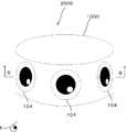
- FIG. 2 is an external view explanatory diagram of an image display body 2000 using an image display sheet 1000.
- FIG. 2 is a cross-sectional view of a main part of an image display body 2000.
- External appearance explanatory drawing of the image display body 3000 by the image display sheet 1000 3 is a cross-sectional view of a main part of an image display body 3000.
- FIG. It is an external appearance explanatory drawing of the image display body 4000 by the image display sheet 1000.
- FIG. It is explanatory drawing which shows the basic characteristic of a lenticular. It is a schematic explanatory drawing which shows the basic principle of a lenticular.
- FIG. 1 is a cross-sectional view of an image display sheet in the present embodiment.
- the image display sheet 100 is formed with the lenticular sheet 1 and the image forming layer 3 as essential components.
- the image forming layer 3 is formed on the image forming medium 2 such as paper will be described. Below, each layer which comprises the image display sheet 100 is demonstrated.
- the lenticular sheet 1 is configured by arranging a plurality of cylindrical lenses 1a in parallel.
- a cylindrical lens 1a formed on the lenticular sheet 1 is shown in the upper part of the drawing.
- the material of the lenticular sheet 1 is not particularly limited as long as it is a lens sheet conventionally used for an image display sheet, but PET (polyethylene terephthalate), PP, PETG (glycol-modified polyethylene terephthalate), acrylic, acrylate-based resin, etc.
- PET polyethylene terephthalate
- PETG glycocol-modified polyethylene terephthalate
- acrylic acrylate-based resin
- the image forming medium 2 is provided on the side of the lenticular sheet 1 that does not have the convex shape of the cylindrical lens 1a, and the image forming layer 3 is formed on the lenticular sheet 1 side.
- the material of the image forming medium 2 is not particularly limited as long as it is an image forming medium conventionally used for an image display sheet, but is not limited to coated paper, synthetic paper, fine paper, medium paper, impregnated paper, laminated paper, metal vapor deposition. Paper, paper such as coated paper for printing, coated paper for recording, polyethylene terephthalate film, polyethylene film, polypropylene film, plastic film such as polycarbonate film, metal foil, or a composite thereof may be used.
- the material of the image forming medium 2 can be appropriately selected according to the strength and application required for the image display sheet 100.
- the image forming layer 3 is a layer in which an image 3a such as a pattern or a character, which is a virtual image observation image, is formed by printing or transferring.
- the image forming layer 3 is provided on the lenticular sheet 1 side of the image forming medium 2.
- the material of the image forming layer 3 is not particularly limited as long as it can adhere to the image forming medium 2.
- a conventionally known ink material is used.
- the ink material may be phosphorescent ink, fluorescent ink, or the like.
- a known method such as adhesion or adhesion is used depending on the material of the image forming medium 2 and the image forming layer 3. Done. It is sufficient that the lenticular sheet 1 and the image forming layer 3 can be laminated while maintaining transparency. That is, it is only necessary that the observer (observer's eye E) can observe the image 3 a formed on the image forming layer 3 from the side of the cylindrical lens 1 a having the convex shape of the lenticular sheet 1. Specifically, it is only necessary to observe a movement based on the image 3a formed on the image forming layer 3, or a virtual image accompanied by movement and deformation.
- FIG. 2 is a diagram illustrating the configuration of the image display sheet according to the present embodiment.
- 2A is a cross-sectional explanatory view of the lenticular sheet
- FIG. 2B is a plan view of the image forming layer
- FIG. 3 is a plan view of the image display sheet of the present embodiment.
- each cylindrical lens 1a when moving the line of sight while changing the viewing angle in the direction of the arrow, the focus of each cylindrical lens 1a when the observer observes from directly above each cylindrical lens 1a. Show the state.
- the focusing surface of the cylindrical lens 1 a is in the image forming layer 3.
- the cylindrical lens 1a is configured to focus on the image 3a.
- the observer is not limited to seeing from just above, but can change the viewing angle and confirm the smooth movement or movement and deformation of the virtual image.
- the image forming layer 3 has a plurality of images 3a.
- the image 3a is repeatedly formed so as to substantially correspond to the cylindrical lens 1a.
- Each of the six eyeball images 3a corresponds to the cylindrical lens 1a.
- the length is configured to have a desired difference.
- the arrangement pitch length A of the cylindrical lenses 1a and the pitch length B of the image 3a are different from each other, and the difference between the arrangement pitch length A of the cylindrical lenses 1a and the pitch length B of the image 3a is It is configured to be 10% or less with respect to the arrangement pitch length A of the cylindrical lenses 1a or the pitch length B of the image 3a.
- the observer sinks the virtual image 4 based on the cylindrical lens 1a and the image 3a below the lenticular sheet 1.
- the virtual image 4 also appears to move to the right, and when it moves to the left, the virtual image 4 appears to move to the left. That is, the virtual image 4 appears to move in the same direction as the line of sight movement.
- the observer floats the virtual image 4 based on the cylindrical lens 1a and the image 3a above the lenticular sheet 1. Looks three-dimensional. When the line of sight is moved to the right, the virtual image 4 appears to move to the left, and when the line of sight is moved to the left, the virtual image 4 appears to move to the right. That is, the virtual image 4 appears to move in the direction opposite to the line of sight movement.
- the pitch length x of the virtual image 4 shown in FIG. 3 is determined based on Expression (1).
- the width y in the arrangement direction of the cylindrical lenses 1a of the virtual image 4 is determined based on Expression (2).
- A is the arrangement pitch length of the cylindrical lenses 1a
- B is the pitch length of the image 3a
- C is the width (lateral size) of the cylindrical lenses 1a in the arrangement direction of the image 3a.
- the height z (vertical size) of the virtual image 4 in the direction orthogonal to the arrangement direction of the cylindrical lenses 1a is the same as the height D (vertical size) of the image 3a in the direction orthogonal to the arrangement direction of the cylindrical lenses 1a. (Formula (3)).
- FIG. 4 is an explanatory diagram of a virtual image according to the present embodiment.
- the image 3a formed on the image forming layer 3 and the virtual image 4 based on the cylindrical lens 1a can be observed from above the lenticular sheet 1 as a pseudo-dynamic image.
- the virtual image 4 sinks below the lenticular sheet 1 and appears three-dimensionally. Furthermore, the virtual image 4 is observed as a virtual image that moves smoothly with the movement of the observer's line of sight.
- the virtual image 4 floats above the lenticular sheet 1 and appears three-dimensionally. Furthermore, the virtual image 4 is observed as a virtual image that moves smoothly with the movement of the observer's line of sight.
- Equations (1) and (2) the smaller the value of
- a plurality of images 3a for causing the image forming layer 3 to act with the cylindrical lens 1a to display a virtual image are repeatedly formed so as to substantially correspond to the cylindrical lens 1a of the lenticular sheet 1.
- the difference between the arrangement pitch length A of the cylindrical lens 1a and the pitch length B of the image 3a is different, and the difference between the arrangement pitch length A of the cylindrical lens 1a and the pitch length B of the image 3a is different from the cylindrical lens 1a. Since the arrangement pitch length A or the pitch length B of the image 3a is 10% or less, an image display sheet capable of observing the virtual image 4 with smooth movement or movement and deformation is realized. it can.
- the size (width C, height D) of the image 3a is about several tens of ⁇ m to several tens of millimeters, it is possible to use general-purpose equipment (for example, general-purpose printing apparatus, transfer apparatus, etc.) without using dedicated equipment.
- the image forming layer 3 can be printed and transferred to the image forming medium 2 using general-purpose image software.
- the difference between the arrangement pitch length A of the cylindrical lens 1a and the pitch length B of the image 3a is relative to the arrangement pitch length A or the pitch length B. It is more preferable that the difference is 0.1% to 4%.
- the image 3a is repeatedly formed so as to substantially correspond to the cylindrical lens 1a, but the corresponding position gradually shifts because the arrangement pitch length A of the cylindrical lenses 1a and the pitch length B of the image 3a are different. Go. Therefore, the cylindrical lens 1a and the image 3a do not exactly correspond one-to-one. A smooth virtual image can be observed when the arrangement pitch length A of the cylindrical lenses 1a and the pitch length B of the image 3a are different.
- each component of the image display sheet is as follows. Thickness of lenticular sheet 1: 0.45 mm, arrangement pitch length A of cylindrical lens 1a: 336 ⁇ m, pitch length B of image 3a: 330 mm, difference between pitch length A and pitch length B: 6 mm, width C of image 3a: 225 ⁇ m, height D of image 3a: 12.7 mm, pitch length x of virtual image 4: 19 mm, width y of virtual image 4: 12.7 mm, height z of virtual image 4: 12.7 mm
- the image display sheet according to the other embodiment 1 is configured to enable observation of one virtual image.
- description is abbreviate
- FIG. 5 is an explanatory diagram of the configuration of the image display sheet according to another embodiment 1, and shows the correspondence between each cylindrical lens 5a of the lenticular sheet 5 and the images 6a and 6b.
- FIG. 6 is an explanatory diagram of the pitch length measurement of the image 6b.
- FIG. 7 is an explanatory diagram of a virtual image according to another embodiment 1.
- FIG. Since the configuration of the lenticular sheet 5 is the same as that of the lenticular sheet 1 described above, the description thereof is omitted.
- a predetermined number of images which are virtual image observation image groups, are formed.
- the image 6a in the vicinity of the center of the image group is an image that is not missing, and the other images 6b other than the image 6a in the vicinity of the center have a notch 6c on the side of the image 6a near the center.
- the images 6a and 6b are formed so as to substantially correspond to the cylindrical lens 5a.
- the image group is configured by a total of 11 images including an image 6a near the center and 10 images 6b having a notch 6c.
- the notch 6c of the image 6b becomes larger as it moves away from the image 6a to the left and right in the drawing.
- FIG. 5 shows the case where the number of the images 6a near the center is one, the number of the images 6a near the center may be plural.
- the images 6a and 6b are formed so as to substantially correspond to the cylindrical lens 5a in the same manner as in the above-described embodiment.
- the difference between the arrangement pitch length A of the cylindrical lenses 5a and the pitch length B of the images 6a and 6b is 0% to 10% with respect to the arrangement pitch length A of the cylindrical lenses 5a or the pitch length B of the images 6a and 6b. Configure to be in range.
- the pitch length B between the image 6a and the image 6b and the pitch length B between the images 6b are set to the pitch length B when it is assumed that the image 6b does not have a notch 6c (FIG. 6).
- the widths y and z of the observed virtual image 7 are determined based on the above-described equations (2) and (3).
- the widths C and D are the widths C and D when it is assumed that the image 6b does not have the notch 6c (FIG. 6).
- the widths C and D are obtained from the image 6a having no chip, the horizontal size of the image 6a is set to the width C and the vertical size is set to the height D.
- the image forming layer 6 may be formed on an image forming medium (not shown), or may be directly formed on the lenticular sheet 5 as in other embodiment 2 described later.
- the configuration of the image forming medium conforms to the image forming medium 2 described above.
- an image display sheet 200 capable of observing only one virtual image 7 as shown in FIG. 7 can be realized.
- one virtual image 7 in which the center image is prominently expressed based on the images 6a and 6b and the cylindrical lens 5a formed on the image forming layer 6 is pseudo-imaged. It can be observed as a dynamic image.
- Example of image display sheet An example of an actual image display sheet according to another embodiment 1 will be described. A design example of each part when only one virtual image of the eyeball is observed will be described.
- each component of the image display sheet is as follows. Thickness of lenticular sheet: 0.45 mm, arrangement pitch length A of cylindrical lenses 5a: 336 mm, pitch length B between images 6a and 6b (and between images 6b): 330 mm, difference between pitch length A and pitch length B : 6 mm, width C of image 6a (and 6b) C: 225 ⁇ m, height D of image 6a (and 6b): 12.7 mm, width y of virtual image 7: 12.7 mm, height z of virtual image 7: 12.7 mm
- FIG. 8 is a cross-sectional view of an image display sheet according to another embodiment 2.
- An image display sheet 300 according to another embodiment 2 is configured to provide an image forming layer on a lenticular sheet.
- the image display sheet 300 is provided with a lenticular sheet 8 and an image forming layer 9 as essential components. Since the configuration of the lenticular sheet 8 is the same as that of the lenticular sheet 1 described above, description thereof is omitted.
- the image forming layer 9 is a layer in which an image 9a such as a pattern or a character, which is a virtual image observation image, is formed by printing or transferring.
- the image forming layer 9 is provided on the surface of the lenticular sheet 8 opposite to the surface having the convex shape of the cylindrical lens 8a.
- the material of the image forming layer 9 is not particularly limited as long as it can be in close contact with the lenticular sheet 8.
- a conventionally known ink material or the like is used.
- the ink material may be phosphorescent ink, fluorescent ink, or the like.
- a plurality of images 9a are repeatedly formed so as to substantially correspond to the cylindrical lenses 8a.
- the arrangement pitch length of the cylindrical lenses 8a is different from the pitch length of the image 9a, and the difference between the arrangement pitch length of the cylindrical lenses 8a and the pitch length of the image 9a is the arrangement pitch length of the cylindrical lenses 8a or the image 9a.
- the pitch length is 10% or less. Since other configurations are the same as those of the image forming layer 3 or the image forming layer 6 described above, the description thereof is omitted. As described above, the image forming layer 3 or the image forming layer 6 may be directly formed on the lenticular sheet 8.
- the image display sheet of the present invention can be combined with a stereoscopic sheet.
- an embodiment in which an image display sheet is combined with a stereoscopic sheet will be described.
- FIG. 9 is a diagram illustrating the configuration of an image display sheet according to another embodiment 3.
- FIG. 10 is a plan view of the image forming layer.
- FIG. 9 shows a cross section of the image display sheet 400.
- the image display sheet 400 includes a virtual image display unit 40a and an observed image display unit 40b.
- the virtual image display unit 40a includes a lenticular sheet 10 common to the observed image display unit 40b, an image forming medium 11 common to the observed image display unit 40b, and the image forming layer 12.
- the observed image display unit 40b includes the lenticular sheet 10 that is common to the virtual image display unit 40a, the image forming medium 11 that is common to the virtual image display unit 40a, and the image forming layer 13.
- the configuration of the lenticular sheet 10 is the same as that of the lenticular sheet 1 described above, the configuration of the image forming medium 11 is the same as that of the image forming medium 2 described above, and the configuration of the image forming layer 12 is the image forming layer 3 or the image forming layer described above. Since it is the same as that of the layer 6, the description is omitted.
- an image 12 a as a virtual image observation image is formed on the image forming layer 12.
- the image forming medium 11 is an image forming medium common to the virtual image display unit 40a and the observed image display unit 40b.
- the image forming layers 12 and 13 are formed on the lenticular sheet 10 side. Since the other configuration of the image forming medium 11 is the same as that of the image forming medium 2 described above, description thereof is omitted.
- the observed image display unit 40b has the configuration and effects of a conventionally known lenticular display.
- the image forming layer 13 of the observed image display unit 40b is a layer in which one or a plurality of other images different from the virtual image observation image (the image 12a in the present embodiment) are formed by printing or transfer.
- the other image is an image such as a pattern or a character which is a stereoscopic image, a changing image, an animation image, or the like.
- the left-eye image 13 a and the right-eye image 13 b that display the image to be observed by operating with the cylindrical lens 10 a of the lenticular sheet 10 are arranged in a stripe pattern.
- the material of the image forming layer 13 is not particularly limited as long as it can adhere to the image forming medium 11. For example, a conventionally known ink material or the like is used.
- the lamination method of the lenticular sheet 10 and the image forming medium 11 is performed using a known method such as adhesion or adhesion depending on the materials of the image forming medium 11 and the image forming layers 12 and 13. It is sufficient that the lenticular sheet 10 and the image forming layers 12 and 13 can be laminated while maintaining transparency.
- the virtual image display unit 40a can observe the virtual image by the action of the image on the image forming layer 12 and the cylindrical lens 10a, and the observed image display unit 40b. Then, the image on the image forming layer 13 and the cylindrical lens 10a act to observe the observed image.
- the image display sheet 400 can be configured by combining the virtual image display unit 40a capable of observing a virtual image and the observed image display unit 40b capable of observing the observed image.
- the case of using two virtual image display units 40a and three observed image display units 40b has been described as an example to simplify the description and illustration.
- a desired display may be used depending on the design of the image display sheet. You may combine the number (plural or singular) of virtual image display sections 40a and the desired number of (plural or singular) observed image display sections 40b.
- the virtual image display unit 40a and the observed image display unit 40b are configured by the same image forming medium 11, a simpler and more stable sheet can be realized.
- the part of both eyes is formed by the virtual image display part 40a, and the part other than both eyes is formed by the observed image display part 40b.
- the observed image display unit 40b is configured as a conventionally known lenticular display, and the image of the image forming layer 13 and the cylindrical lens 10a act to observe a stereoscopic observed image. It was configured as follows. However, the present invention is not limited to this. For example, a two-dimensional image that is not an image that exhibits special effects such as a stereoscopic image or a changing image by acting with a cylindrical lens, such as an image of an illustration, a face, or a face photograph, may be used as the observed image display unit 40b.
- the two-dimensional image may be an image serving as a background of the virtual image display unit 40a.
- the lenticular sheet 10 may not be configured in the observed image display unit 40b.
- FIG. 11 is a cross-sectional view of an image display sheet according to another embodiment 4.
- the image display sheet 500 is formed with the plano-convex lens sheet 15 and the image forming layer 17 as essential components.
- the image forming layer 16 is formed on an image forming medium such as paper will be described. Below, each layer which comprises the image display sheet 500 is demonstrated.
- the plano-convex lens sheet 15 is configured by a honeycomb arrangement or a square arrangement of a plurality of plano-convex lenses 15a.
- the plano-convex lens 15a configured on the plano-convex lens sheet 15 is shown in the upper part of the drawing.
- the material of the plano-convex lens sheet 15 is not particularly limited as long as it is a lens sheet conventionally used for an image display sheet, but PET (polyethylene terephthalate), PP, PETG (glycol-modified polyethylene terephthalate), acrylic, acrylate-based resin, etc.
- the transparent resin material is used.
- the image forming medium 16 is provided on the side of the plano-convex lens sheet 15 that does not have the convex shape of the plano-convex lens 15a, and the image forming layer 16 is formed on the plano-convex lens sheet 15 side. Since other configurations of the image forming medium 16 are the same as those of the image forming medium 2 described above, description thereof will be omitted.
- the image forming layer 17 is a layer in which an image 17a such as a pattern or a character, which is a virtual image observation image, is formed by printing or transferring.
- the image forming layer 17 is provided on the plano-convex lens sheet 15 side of the image forming medium 16.
- the material of the image forming layer 3 is not particularly limited as long as it can adhere to the image forming medium 2.
- a conventionally known ink material is used.
- the ink material may be phosphorescent ink, fluorescent ink, or the like. Since the other structure of the image forming layer 17 is the same as that of the image forming layer 3 described above, the description thereof is omitted.
- the focus surface of the plano-convex lens 15 a is in the image forming layer 17.
- the plano-convex lens 15a is configured to focus on the image 17a.
- the lamination method of the plano-convex lens sheet 15 and the image forming medium 16 provided with the image forming layer 17 uses a known method such as adhesion or adhesion depending on the material of the image forming medium 16 and the image forming layer 17. Done. It is only necessary that the plano-convex lens sheet 15 and the image forming layer 17 can be laminated while maintaining transparency.
- the observer can observe the image 17a formed on the image forming layer 17 from the side of the planoconvex lens sheet 15 having the convex shape of the planoconvex lens 15a. Specifically, it is only necessary to observe a movement based on the image 17a formed on the image forming layer 17, or a virtual image accompanying movement and deformation.
- FIG. 12A is a configuration explanatory diagram of an image display sheet according to another embodiment 4.
- FIG. 12A is a plan view of a plano-convex lens sheet
- FIG. 12B is a plan view of an image forming layer.
- FIG. 13 and FIG. 14 are diagrams illustrating the configuration of a virtual image according to another embodiment 4.
- FIG. 12A is an example of a plano-convex lens sheet 15 having a honeycomb arrangement.
- a plurality of images 17 a are formed on the image forming layer 17.
- the image 17a is repeatedly formed so as to substantially correspond to the plano-convex lens 15a.
- 30 eyeball images 17a correspond to the plano-convex lens 15a.
- the arrangement pitch length of the plano-convex lens 15a and the pitch length of the image 17a are different, and the difference between the arrangement pitch length of the plano-convex lens 15a and the pitch length of the image 17a is the pitch of the arrangement pitch length of the plano-convex lens 15a or the pitch of the image 17a. It comprises so that it may become 10% or less with respect to length. In the example of FIGS.
- pitch length B 1 of FIG lateral array pitch length A 1 and the image 17a in the figure next to the plano-convex lens 15a (horizontal direction) are different, and the difference is flat configured so as to be 10% or less with respect to pitch length B 1 of the array pitch length a 1 or the image 17a of the convex lens 15a, in view of the arrangement pitch length a 2 and the image 17a of the vertical in the figure in the plano-convex lens 15a (vertical direction) next pitch length B 2 constitutes different, and, with respect to pitch length B 2 of the arrangement pitch length a 2 or the image 17a of the difference is a plano-convex lens 15a is configured to be 10% or less.
- the observer When the pitch length B 1 (B 2 ) of the image 17a is smaller than the arrangement pitch length A 1 (A 2 ) of the plano-convex lens 15a (A 1 > B 1 and A 2 > B 2 ), the observer The virtual image 18 based on the plano-convex lens 15a and the image 17a sinks below the plano-convex lens sheet 15 and appears three-dimensionally. Then, as shown in FIG. 13, when the line of sight is moved to the right, the virtual image 18 appears to move to the right, and when it moves to the left, the virtual image 18 also appears to move to the left. That is, the virtual image 18 appears to move in the same direction as the line of sight movement.
- the observer The virtual image 18 based on the plano-convex lens 15 a and the image 17 a floats above the plano-convex lens sheet 15 and appears three-dimensionally.
- the virtual image 18 appears to move to the left, and when the line of sight moves to the left, the virtual image 18 appears to move to the right. That is, the virtual image 18 appears to move in the direction opposite to the line-of-sight movement.
- FIGS. 13 and 14 when the observer changes the viewing angle and moves the line of sight, the virtual image 18 based on the image 17 a formed on the image forming layer 17 and the plano-convex lens 15 a is formed on the plano-convex lens sheet 15. Observable from above.
- FIG. 13 shows the state of the virtual image 18 when the line of sight is moved in the horizontal direction.
- FIG. 14 shows a state of the virtual image 18 when the line of sight is moved in the vertical direction.
- Pitch length x 1 of the virtual image 18 shown in FIG. 13 is determined based on equation (1).
- the horizontal width y 1 of the virtual image 18 is determined based on Expression (2).
- A is the arrangement pitch length A 1 of the plano-convex lenses 15a
- B is the horizontal pitch length B 1 of the image 17a
- C is the horizontal width C 1 (lateral size) of the image 17a.
- Pitch length x 2 of the virtual image 18 shown in FIG. 14 is determined based on equation (1).
- the vertical width y 2 of the virtual image 18 is determined based on Expression (2).
- A is the arrangement pitch length A 2 of the plano-convex lenses 15a
- B is the vertical pitch length B 2 of the image 17a
- C is the vertical height C 2 (vertical size) of the image 17a. .
- Equations (1) and (2) the smaller the value of
- the image display sheet 500 that can observe a virtual image that moves smoothly even if a plano-convex lens sheet is used.
- the virtual image 18 based on the image 17a formed on the image forming layer 17 and the plano-convex lens 15a can be observed.
- the image forming layer 17 is formed on the image forming medium 16, it may be directly formed on the surface opposite to the surface having the plano-convex lens of the plano-convex lens sheet 15 according to the other embodiment 2 described above.
- the image display sheet 500 is configured in combination with a conventionally known stereoscopic sheet according to the other embodiment 3 described above, and can observe an observed image by the action of a stereoscopic image, a changing image, an animation image, or a combination thereof. You can also In this case, the image 17a functions as the virtual image observation image of the present invention.
- the image display sheet 500 can constitute an image display sheet for observing only one virtual image according to the other embodiment 1 described above.
- this will be described in detail as another embodiment 5.
- An image forming layer when observing only one virtual image using a plano-convex lens sheet will be described.
- the plano-convex lens sheet and the image forming medium have the same configurations as those of the other embodiment 4.
- FIG. 15 is a plan view of an image forming layer of an image display sheet according to another embodiment 5.
- a predetermined number of images 19a and 19b which are virtual image observation image groups, are formed.
- the image 19a in the vicinity of the center of the image group is an image that is not missing, and the other images 19b other than the image 19a in the vicinity of the center have a notch 19c on the side of the image 19a near the center.
- the images 19a and 19b are formed so as to substantially correspond to a plano-convex lens (not shown).
- the image group includes an image 19a near the center and a plurality of images 19b having a notch 19c.
- the notch portion 19c of the image 19b becomes larger as the distance from the image 19a increases.
- FIG. 15 shows a case where the number of the images 19a near the center is one, the number of the images 19a near the center may be plural.
- the arrangement pitch length of the plano-convex lens is different from the pitch length of the images 19a and 19b, and the difference between the arrangement pitch length of the plano-convex lens and the pitch length of the images 19a and 19b is the arrangement pitch length of the plano-convex lens or the image 19a. And 19b with respect to the pitch length of 19b.
- a plano-convex lens in the horizontal direction of the array pitch lengths A 1 and the pitch length B 1 in the horizontal direction constitute different image 19a
- the horizontal arrangement pitch length A 1 or the image 19a of the difference is a plano-convex lens constituting the horizontal pitch length B 1 to so as to be 10% or less.
- the pitch length B 2 in the vertical direction is configured differently plano vertical arrangement pitch length A 2 and the image 19a, the vertical direction of the difference is a plano-convex lens in the vertical direction of the arrangement pitch length A 2 or the image 19a configuring such that the relative pitch length B 2 10% or less.
- the pitch length B 1 and B 2 between the image 19a and the image 19b, the pitch length B 1 and B 2 between the image 19b, the pitch length between the image 19b, assuming that there is no out portion 19c is the image 19b B and 1 and B 2.
- Pitch length x 1 in the horizontal direction of the virtual image (not shown) is determined based on equation (1).
- the horizontal width y 1 of the virtual image is determined based on Expression (2).
- A is the arrangement pitch length A 1 of the plano-convex lenses
- B is the horizontal pitch length B 1 of the images 19a and 19b
- C is the horizontal width C 1 (horizontal size) of the image 19a. .
- the pitch length x 2 in the vertical direction of the virtual image (not shown) is determined based on equation (1).
- the vertical width y 2 of the virtual image is determined based on Expression (2).
- A is the arrangement pitch length A 2 of the plano-convex lenses
- B is the vertical pitch length B 2 of the images 19a and 19b
- C is the vertical height C 2 (vertical size) of the images 19a and 19b. ).
- the image forming layer may be provided directly on the surface of the lenticular sheet opposite to the surface having the convex shape of the cylindrical lens in accordance with the other embodiment 2.
- the image forming layer may be directly provided on the surface of the plano-convex lens sheet opposite to the surface having the convex shape of the plano-convex lens according to other embodiment 2. .
- the centerpiece is a virtual image observation image.
- a virtual image observation image not only the centerpiece but also a virtual image based on images such as various patterns and characters can be observed.
- a closed eyeball image and an open eyeball image are used as the virtual image observation image
- a virtual image with deformation that opens and closes the eyes can be observed.
- an image of an open mouth and an image of a closed mouth, or an image of an open flower and an image of a closed flower are used as virtual image observation images, there are a wide variety of movements and deformations.
- a virtual image can be realized.
- the case where the image of the arrow is a virtual image observation image will be described with reference to FIG.
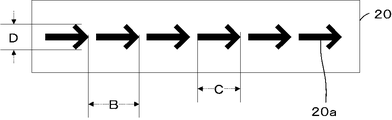
- FIG. 16A and 16B are plan views of an image forming layer of an image display sheet according to another embodiment 6.
- FIG. 16A and FIG. 16B are examples of an image forming layer in which an arrow is an image for virtual image observation.
- a plurality of images 20a as virtual image observation images are formed on the image forming layer 20 shown in FIG. 16A.
- the image 20a is repeatedly formed so as to substantially correspond to a cylindrical lens (not shown) of the lenticular sheet.
- the arrangement pitch length of the cylindrical lens and the pitch length B of the image 20a are configured to be different, and the difference is configured to be 10% or less with respect to the arrangement pitch length of the cylindrical lens or the pitch length B of the image 20a.
- the image forming layer 20 may be formed on an image forming medium (not shown), or may be directly formed on a lenticular sheet as in the second embodiment.
- the configuration of the image forming medium may be the same as that of the image forming medium 2 described above.
- a virtual image indicating an arrow based on the image 20a and the cylindrical lens can be observed from above the lenticular as a pseudo dynamic image. Also, by appropriately adjusting and changing the arrangement pitch length of the cylindrical lenses, the pitch length B of the image 20a, the width C of the image 20a in the arrangement direction of the cylindrical lenses, and the height D of the image 20a, the above formulas (1) to (1) The size of the virtual image observed based on (3) can be freely set.
- a plurality of images 21a as virtual image observation images are formed. Since the configuration of the image 21a is the same as the configuration of the image 20a, description thereof is omitted.
- a virtual image indicating an arrow based on the image 21a and a cylindrical lens can be observed from above the lenticular as a pseudo dynamic image. Further, by appropriately adjusting and changing the arrangement pitch length of the cylindrical lenses, the pitch length B of the image 20a, the width C of the image 21a in the arrangement direction of the cylindrical lenses, and the height D of the image 21a, the above expressions (1) to (1) The size of the virtual image observed based on (3) can be freely set.
- the pitch length B of the image 20a (or the image 21a) is smaller than the arrangement pitch length A (not shown) of the cylindrical lenses (A> B)
- the observer can see the cylindrical lens and the image 20a (or the image 21a).
- a virtual image showing an arrow based on it sinks below the lenticular sheet and appears three-dimensional.
- the virtual image indicating the arrow appears to move to the right
- the virtual image indicating the arrow appears to move to the left. That is, a virtual image indicating an arrow appears to move in the same direction as the line of sight movement. Since the virtual image indicating the arrow along with the direction of movement of the person appears to move in the same direction, it can be effectively used for guiding the direction of travel.
- the observer can connect the cylindrical lens and the image 20a (or the image 21a).
- a virtual image showing an arrow based on () floats above the lenticular sheet and appears three-dimensional.
- the observer sees a virtual image having a shape obtained by rotating the image 20a (or the image 21a) by 180 degrees.
- the virtual image indicating the arrow appears to move to the left
- the virtual image indicating the arrow appears to move to the right. That is, the virtual image indicating the arrow appears to move in the direction opposite to the line-of-sight movement.
- a person can be effectively used for guidance in the direction opposite to the traveling direction.
- a convex body such as a plano-convex lens or a meniscus lens may be provided above the lenticular sheet.
- the image display sheet according to another embodiment 7 has a configuration including a plano-convex lens above the lenticular sheet.
- description is abbreviate
- FIG. 17A is a configuration explanatory diagram of an image display sheet according to another embodiment 7.
- FIG. 17A is a cross-sectional view of an image display sheet.
- the image display sheet 600 shown in FIG. 17A is provided with a lenticular sheet 61, an image forming layer 63, and a plano-convex lens 64 as another convex lens as essential components.
- the lenticular sheet 61 is configured by arranging a plurality of cylindrical lenses 61a in parallel.
- the image forming medium 62 is provided on the side of the lenticular sheet 61 that does not have the convex shape of the cylindrical lens 61a, and the image forming layer 63 is formed on the lenticular sheet 61 side.
- the image forming layer 63 is a layer in which an image 63a such as a pattern or a character, which is a virtual image observation image, is formed by printing or transfer.
- the image forming layer 63 is provided on the lenticular sheet 61 side of the image forming medium 62.
- the plano-convex lens 64 is provided on the side of the lenticular sheet 61 having the convex shape of the cylindrical lens 61a.
- the plano-convex lens 64 has a convex shape on the side opposite to the lenticular sheet 61 (upward in the drawing).
- the material of the plano-convex lens 64 is not particularly limited, but a transparent resin material such as glass, PET (polyethylene terephthalate), PP, PETG (glycol-modified polyethylene terephthalate), acrylic, and acrylate resin is used.
- FIG. 17B is a cross-sectional view of the main part showing the focus state of the lenticular sheet.
- the focal point of the cylindrical lens 61 a alone is configured to converge below the image forming layer 63. Due to the action of the cylindrical lens 61 a and the plano-convex lens 64, the focus from above the plano-convex lens 64 is configured to match the image 63 a formed on the image forming layer 63.
- lenticular sheet 61 Other configurations of the lenticular sheet 61 are the same as those of the lenticular sheet 1 described above.
- the configuration of the image forming medium 62 is the same as that of the image forming medium 2 described above, and the configuration of the image forming layer 63 is the same as that of the image forming layer 3 or the image forming layer 6 described above.
- the plano-convex lens 64 as another convex lens is provided on the side of the lenticular sheet 61 having the convex shape of the cylindrical lens 61a so that the image 63 is focused through the plano-convex lens 64 and the cylindrical lens 61a. Accordingly, a virtual image that moves smoothly can be observed even when the plano-convex lens 64 and the cylindrical lens 61a are used. It is possible to prevent the observer from directly touching the surface of the cylindrical lens 61a of the lenticular sheet 61.
- the shape of the plano-convex lens 64 can constitute an image display sheet 600 that is visually and tactilely close to the eyeball.
- the plano-convex lens 64 of the image display sheet 600 is configured to be separated from the cylindrical lens 61a of the lenticular sheet 61 by a predetermined distance.
- the plano-convex lens is disposed on the cylindrical lens. May be.
- FIG. 17C is an example of an image display sheet having a different plano-convex lens arrangement.
- An image display sheet 700 shown in FIG. 17C is provided with a lenticular sheet 71, an image forming layer 73, and a plano-convex lens 74 as another convex lens as essential components.
- the configuration of the lenticular sheet 71 is the same as that of the lenticular sheet 61 described above
- the configuration of the image forming medium 72 is the same as that of the image forming medium 62 described above
- the configuration of the image forming layer 73 is the same as that of the image forming layer 63 described above.
- the configuration of the image 73a is the same as that of the image forming layer 63a described above.
- the plano-convex lens 74 is provided on the cylindrical lens 71a constituting the lenticular sheet 71 in contact with the cylindrical lens 71a.
- plano-convex lens 74 as another convex lens may be configured on the side having the convex shape of the cylindrical lens 71a of the lenticular sheet 71 and separated from the cylindrical lens 71a by a predetermined distance (FIG. 17A), or Alternatively, it may be configured in contact with the cylindrical lens 71a (FIG. 17C).
- the image display sheet according to another embodiment 8 has a configuration in which a meniscus lens is provided above the lenticular sheet.
- description is abbreviate
- FIG. 18A is a configuration explanatory diagram of an image display sheet according to another embodiment 8.
- 18A is a cross-sectional view of an image display sheet.
- An image display sheet 800 shown in FIG. 18A is provided with a lenticular sheet 81, an image forming layer 83, and a meniscus lens 84 as another convex lens as essential components.
- the lenticular sheet 81 is configured by arranging a plurality of cylindrical lenses 81a in parallel.
- the image forming medium 82 is provided on the side of the lenticular sheet 81 that does not have the convex shape of the cylindrical lens 81a, and the image forming layer 83 is formed on the lenticular sheet 81 side.
- the image forming layer 83 is a layer in which an image 83a such as a pattern or a character, which is a virtual image observation image, is formed by printing or transfer.
- the image forming layer 83 is provided on the lenticular sheet 81 side of the image forming medium 82.
- the meniscus lens 84 is provided on the side of the lenticular sheet 81 having the convex shape of the cylindrical lens 81a.
- the meniscus lens 84 has a convex shape on the side opposite to the lenticular sheet 81 (upward in the drawing).
- the material of the meniscus lens 84 is not particularly limited, and a transparent resin material such as glass, PET (polyethylene terephthalate), PP, PETG (glycol-modified polyethylene terephthalate), acrylic, and acrylate resin is used.
- the focal point of the cylindrical lens 81 a alone is configured to converge below the image forming layer 83.
- the state of focusing by the cylindrical lens 81a alone is the same as that of the cylindrical lens 71a of FIG. Due to the action of the cylindrical lens 81 a and the meniscus lens 84, the focus from above the meniscus lens 84 is configured to match the image 83 a formed on the image forming layer 83.
- lenticular sheet 81 Other configurations of the lenticular sheet 81 are the same as those of the lenticular sheet 61 described above.
- the configuration of the image forming medium 82 is the same as that of the image forming medium 62 described above, and the configuration of the image forming layer 83 is the same as that of the image forming layer 63 described above.
- the meniscus lens 84 as another convex lens is provided on the side of the lenticular sheet 81 having the convex shape of the cylindrical lens 81a, and the image 83 is focused through the meniscus lens 84 and the cylindrical lens 81a. Accordingly, a virtual image that moves smoothly can be observed even when the meniscus lens 84 and the cylindrical lens 81a are used. It is possible to prevent the observer from directly touching the surface of the cylindrical lens 81a of the lenticular sheet 81.
- the shape of the meniscus lens 84 can constitute the image display sheet 800 that is visually and tactilely close to the eyeball.
- the meniscus lens 84 of the image display sheet 800 is configured to be separated from the cylindrical lens 81a of the lenticular sheet 81 by a predetermined distance.
- the meniscus lens may be disposed on the cylindrical lens. Good.
- FIG. 18B is an example of an image display sheet having a different meniscus lens arrangement.
- the image display sheet 900 shown in FIG. 18B is provided with a lenticular sheet 91, an image forming layer 93, and a meniscus lens 94 as another convex lens as essential components.
- the configuration of the lenticular sheet 91 is the same as that of the lenticular sheet 81 described above
- the configuration of the image forming medium 92 is the same as that of the image forming medium 82 described above
- the configuration of the image forming layer 93 is the same as that of the image forming layer 83 described above.
- the configuration of the image 93a is the same as that of the image forming layer 83a described above.
- the meniscus lens 94 is provided on the cylindrical lens 91a constituting the lenticular sheet 91 in contact with the cylindrical lens 91a.
- the meniscus lens 94 as another convex lens may be configured to be separated from the cylindrical lens 91a by a predetermined distance on the side of the lenticular sheet 91 having the convex shape of the cylindrical lens 91a (FIG. 18A). Or you may comprise in contact with the cylindrical lens 91a (FIG. 18B).
- plano-convex lenses and meniscus lenses examples using plano-convex lenses and meniscus lenses have been described, but the present invention is not limited to plano-convex lenses and meniscus lenses.
- a convex glass plate or a plastic plate may be used as long as it can work with the cylindrical lens to focus on the image of the image forming layer.
- the image forming layer may be directly formed on the lenticular sheet according to the second embodiment described above.
- a stereoscopic image, a changing image, an animation image, or a combination thereof can be configured to be observable.
- a plano-convex lens sheet may be used according to the other embodiments 4 and 5 described above.
- the convex surface of the plano-convex lens or meniscus lens is configured to be opposite to the lenticular sheet (upward in the figure).
- the convex surface of the plano-convex lens or meniscus lens may be configured to be on the lenticular sheet side (downward in the figure).
- the convex surface of the plano-convex lens or meniscus lens may be located on the opposite side of the plano-convex lens sheet or on the plano-convex lens sheet side.
- the image display sheet according to another embodiment 9 configures a virtual image that moves smoothly as the line of sight moves so as to be stationary.
- description is abbreviate
- FIG. 19A is a configuration explanatory diagram of an image display sheet according to another embodiment 9. The correspondence between each cylindrical lens 111a of the lenticular sheet 111 and the images 113a and 113b is shown. In addition, since the structure of the lenticular sheet 111 is the same as that of the lenticular sheet 1 mentioned above, description is abbreviate
- the image forming layer 113 a predetermined number of images 113a and 113b, which are virtual image observation image groups, are formed.
- the virtual image observation image group includes a still virtual image observation image group including a predetermined number (for example, several tens) of still virtual image observation images.
- the image 113b which is a still virtual image observation image, is for configuring a virtual image so as to be stationary.
- a still virtual image observation image group composed of eight images 113b is formed at both ends of the virtual image observation image group.
- the images 113a and 113b are repeatedly formed so as to substantially correspond to the cylindrical lens 1a.
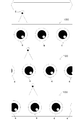
- FIG. 19B is an explanatory diagram of the original image 113Xa and the original image 113Xb.
- 19C and 19D are examples of creating a still virtual image observation image group.
- the image 113a that is not the still virtual image observation image has the same configuration as the above-described image 3a, and thus the description thereof is omitted.
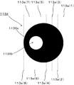
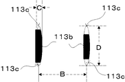
- the image 113b includes two elements, a black circle and a white circle.
- the original image 113X of the image 113b includes an original image 113Xa that is the origin of a black circle and an original image 113Xb that is the origin of a white circle.
- the image 113b is formed by forming a missing portion 113c and an extended portion 113d with respect to the original image 113Xa and the original image Xb, respectively, and reducing it to a predetermined size.
- a plurality of auxiliary lines 113e are defined for the original image 113X.
- the number of auxiliary lines 113e of the number of images 113b constituting the still virtual image observation image group and the auxiliary lines 113e for creating the extension 113d in the image 113b are defined.
- the image group for left virtual image observation at the left end of the image forming layer 113 is composed of six images 113b, and thus six auxiliary lines 113e and two auxiliary lines for creating the extension 113d.
- a total of eight auxiliary lines (auxiliary lines 113e (1), 113e (2), 113e (3),... 113e (8)) of the line 113e are defined. Arrange each auxiliary line at equal or unequal intervals.
- the extension unit 113d created in the image 113b is created on the image 113a side. Therefore, the image 113b constituting the image group for still virtual image observation on the left side of the image forming layer 113 creates an extension portion 113d using the auxiliary line 113e (1), and is used for observation of the still virtual image on the right side of the image forming layer 113.
- the extension 113d is created using the auxiliary line 113e (8). Therefore, since the auxiliary line 113e (8) is not used in the image 113b constituting the image group for still virtual image observation on the left side of the image forming layer 113, only the seven auxiliary lines 113e (1) to 113e (7) are used from the beginning.
- auxiliary line 113e (1) is not used for the image 113b that forms the still image observation image group on the right side of the image forming layer 113, only the seven auxiliary lines 113e (2) to 113e (8) are used from the beginning. It may be defined. In order to simplify the description, a case will be described in which eight auxiliary lines are drawn on the original image 113X regardless of which of the left and right still virtual image observation image groups is the image 113b.
- auxiliary lines 113e (1) and 113e (8) for creating the extension 113d are tangents to the original image 113X.
- all or any of the auxiliary lines 113e (1) to (8) may be referred to as the auxiliary line 113e.
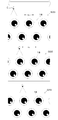
- FIG. 19C and FIG. 19D are examples of creating a still virtual image observation image group.
- FIG. 19C is an example of creation of a still virtual image observation image group on the left side of the image forming layer 113 shown in FIG. 19A.
- FIG. 19D is a creation of a still virtual image observation image group on the right side of the image forming layer 113 shown in FIG. 19A. It is an example.
- the still virtual image observation image group shown in FIGS. 19C and 19D will be described as an example in which each group is composed of six images 113b.
- the auxiliary line 113e and an intersection point P described later are for defining the notch 113c and the extension 113d and are not drawn on the image forming layer 113.
- Each original image 113X is deformed based on the perpendicular drawn to the auxiliary line 113e (1) from the intersection of the auxiliary lines 113e (2) to 113e (7) and the original image 113X.
- each of the auxiliary lines 113e (2) to 113e (7) and each original image 113X is intersected based on a perpendicular drawn to the auxiliary line 113e (1) from the intersection point P of each original image 113X.
- Each of the original images 113X is deformed (C-2).
- the original image 113X includes original images 113Xa and 113Xb.
- each original image 113Xa is deformed based on the perpendicular drawn from the intersection P between each auxiliary line 113e (2) to 113e (7) and each original image 113Xa to the auxiliary line 113e (1).
- each original image 113Xb is converted based on a perpendicular line drawn from the intersection P between each auxiliary line 113e (2) to 113e (7) and each original image 113Xb to the auxiliary line 113e (1). Deform.
- the auxiliary line 113e (2) and the original image 113Xa are two.
- a perpendicular line is drawn from the intersection point P to the auxiliary line 113e (1).
- a perpendicular line is drawn to the auxiliary line 113e (1) from two intersection points P of the auxiliary line 113e (3) and the original image 113Xa.
- a perpendicular line is drawn to the auxiliary line 113e (1) from two intersection points P of the auxiliary line 113e (4) and the original image 113Xa.
- a perpendicular line is drawn to the auxiliary line 113e (1) from two intersection points P of the auxiliary line 113e (5) and the original image 113Xa.
- a perpendicular line is also drawn to the auxiliary line 113e (1) from the two intersections P of the auxiliary line 113e (5) and the original image 113Xb.
- a perpendicular line is drawn to the auxiliary line 113e (1) from two intersection points P of the auxiliary line 113e (6) and the original image 113Xa. Then, a perpendicular line is also drawn to the auxiliary line 113e (1) from two intersection points P of the auxiliary line 113e (6) and the original image 113Xb.
- a perpendicular line is drawn to the auxiliary line 113e (1) from two intersection points P of the auxiliary line 113e (7) and the original image 113Xa. Pull.
- the original image 113X is deformed based on the auxiliary line 113e (1) and the perpendicular line.
- the original image 113X is deformed based on the auxiliary line 113e (1) and the perpendicular line.
- the original image 113X has an extension part 113d on the image 113a side (right side in FIG. 19C). More specifically, the extended portion 113d is created by the auxiliary line 113e (1) and the vertical line.
- the at least one image 113b positioned on the left end side of the virtual image observation image group has a notch portion 113c at both ends in a direction perpendicular to the direction in which the image 113a and the image 113b which are virtual image observation images are arranged.
- the auxiliary lines 113e (2) to 113e (7) having the intersection P are located on the left side of the center of the original image 113Xa (in other words, the original image In the case of being located farther from the image 113a than the center of the 113Xa), the original image 113Xa has a notch 113c above and below.
- the original image 113Xb when the auxiliary lines 113e (2) to 113e (7) having the intersection point P are located on the left side of the center of the original image 113Xb (in other words, from the image 113b than the center of the original image 113Xa). In the case of being located on the far side), the original image 113Xb has a notch 113c above and below.
- the deformed original image 113X is reduced to a predetermined size to create an image 113b (C-4).
- C-4 six images 113b are created.
- Each original image 113X is deformed based on a perpendicular drawn to the auxiliary line 113e (8) from the intersection of the auxiliary lines 113e (7) to 113e (2) and the original image 113X.
- each of the auxiliary lines 113e (7) to 113e (2) and each original image 113X based on the perpendicular drawn to the auxiliary line 113e (8) from the intersection point P of each original image 113X.
- Each of the original images 113X is deformed (D-2).
- the original image 113X includes original images 113Xa and 113Xb.
- each original image 113Xa is deformed based on the perpendicular drawn from the intersection P between each auxiliary line 113e (7) to 113e (2) and each original image 113Xa to the auxiliary line 113e (8).
- Each original image 113Xb is deformed based on a perpendicular drawn to the auxiliary line 113e (8) from the intersection point P between each auxiliary line 113e (7) to 113e (2) and each original image 113Xb.
- auxiliary lines 113e (7) and the original image 113Xa.
- a perpendicular line is drawn from the intersection point P to the auxiliary line 113e (8).
- a perpendicular line is drawn to the auxiliary line 113e (8) from two intersection points P of the auxiliary line 113e (6) and the original image 113Xa.
- a perpendicular line is also drawn to the auxiliary line 113e (8) from two intersection points P of the auxiliary line 113e (6) and the original image 113Xb.
- a perpendicular line is drawn to the auxiliary line 113e (8) from two intersection points P of the auxiliary line 113e (5) and the original image 113Xa.
- a perpendicular line is also drawn to the auxiliary line 113e (8) from two intersection points P of the auxiliary line 113e (5) and the original image 113Xb.
- a perpendicular line is drawn to the auxiliary line 113e (8) from two intersection points P of the auxiliary line 113e (4) and the original image 113Xa.
- a perpendicular line is drawn to the auxiliary line 113e (8) from two intersection points P of the auxiliary line 113e (3) and the original image 113Xa.
- a perpendicular line is drawn to the auxiliary line 113e (8) from the two intersection points P of the auxiliary line 113e (2) and the original image 113Xa. Pull.
- the original image 113X is deformed based on the auxiliary line 113e (8) and the perpendicular line.
- the original image 113X is deformed based on the auxiliary line 113e (8) and the perpendicular line.
- the original image 113X has an extended portion 113d on the image 113a side (left side in FIG. 19D). More specifically, the extended portion 113d is created by the auxiliary line 113e (8) and the vertical line.
- At least one or more images 113b positioned on the right end side of the virtual image observation image group have notches 113c at both ends in the direction perpendicular to the direction in which the images 113a and 113b are arranged.
- the auxiliary lines 113e (7) to 113e (2) having the intersection P are located on the right side of the center of the original image 113Xa (in other words, the original image In the case of being located farther from the image 113a than the center of the 113Xa), the original image 113Xa has a notch 113c above and below.
- the original image 113Xb when the auxiliary lines 113e (7) to 113e (2) having the intersection point P are located on the right side of the center of the original image 113Xb (in other words, from the image 113a than the center of the original image 113Xa). In the case of being located on the far side), the original image 113Xb has a notch 113c above and below.
- the deformed original image 113X is reduced to a predetermined size to create an image 113b (D-4).
- D-4 six images 113b are created.
- a still virtual image observation image group is formed on the image forming layer 113 by the image 113b created as described above (FIG. 19A).
- the images 113a and 113b are formed so as to substantially correspond to the cylindrical lens 111a in the same manner as in the above-described embodiment.
- the arrangement pitch length A of the cylindrical lenses 111a is different from the pitch length B of the images 113a and 113b, and the difference between the arrangement pitch length A of the cylindrical lenses 1a and the pitch length B of the image 3a is
- the arrangement pitch length A of the lenses 111a or the pitch length B of the images 113a and 113b is 10% or less.
- the pitch length B between the image 113a and the image 113b and the pitch length B between the images 113b are set to the pitch length B when it is assumed that the image 113b does not have the missing portion 113c or the extended portion 113d.
- the widths C and D are the widths C and D when it is assumed that the image 113b does not have the lacking portion 113c (FIG. 19E).
- the image forming layer 113 may be formed on an image forming medium (not shown), or may be directly formed on the lenticular sheet 111 as in the second embodiment.
- the configuration of the image forming medium conforms to the image forming medium 2 described above.
- the virtual virtual image observation image group includes the stationary virtual image observation image group including the predetermined number of images 113b at the end portion, and the image 113b includes the expansion unit.
- the moving virtual image 114 can be stopped (stopped) at a predetermined position.
- FIG. 20 is a diagram illustrating the configuration of a virtual image. (A-1) to (A-4) show the movement of the virtual image when the line of sight is moved to the right on the image display sheet 1100. When the line of sight is moved to the right on the image display sheet 1100, the virtual image 114 moves to the right ((A-1) ⁇ (A-2)), and even if the line of sight is further moved to the right, the virtual image remains stationary without moving ( (A-3) and (A-4)).
- (B-1) to (B-4) show the movement of the virtual image when the line of sight is moved to the left on the image display sheet 1100.
- the virtual image 114 moves to the left ((B-1) ⁇ (B-2)), and even if the line of sight is further moved to the left, the virtual image remains stationary without moving ( (B-3) and (B-4)).
- the still virtual image observation image group including the images 113b an image display sheet capable of observing a static virtual image can be realized.
- FIG. 21 is an explanatory diagram of an application example of another embodiment 9.
- the auxiliary line 113e (1) is defined at a position away from the original image 113X.
- the original image X is deformed based on the perpendicular drawn to the auxiliary line 113e (1) from the intersection point P of the auxiliary lines 113e (2) to 113e (7) and the original image 113X.
- a larger extended portion 113d can be formed.
- the virtual image stops. If the line of sight continues to move to the left after the virtual image has stopped, the static virtual image will not be visible. However, in the example of FIG. 21, the image 113b has a wider extension 113d. Therefore, when the virtual image continues to move to the left after being stationary, the image 113b is stationary for a longer time than in the case of the image 113b illustrated in FIG. 19C. You can continue to observe the virtual image.
- the image 113b which is a still virtual image observation image, may be configured to include at least the missing portion 113c and the expanding portion 113d.
- the virtual image observation image group is configured to have the still virtual image observation image group including the predetermined number of images 113b at both ends, but the still virtual image including the image 113a only on one end side. You may comprise so that it may have an image group for observation. For example, in FIG. 19A, if the image 113a is configured to have a still virtual image observation image group only on the left side of the image 113a, when the line of sight is moved to the right on the image display sheet 1100, the virtual image 114 continues to move without stopping and moves to the right. Then, the virtual image 114 can be configured to move to the left and then rest.
- the image forming layer 113 is configured to include the image 113a that is a virtual image observation image that is not a still virtual image observation image, but the present invention can be realized without the image 113a.
- the method of reducing the size to a predetermined size after forming the missing portion 113c and the extended portion 113d with respect to the original images 113Xa and Xb has been described, but the present invention is not limited to this.
- the cutout portion 113c and the extended portion 113d may be formed after the original image 113X is reduced to a predetermined size.
- the original image 113X is used as a method of forming the missing portion 113c and the extended portion 113d in the image 113b, but the present invention is not limited to this. Any method can be used as long as the notch 113c and the extended portion 113d can be formed in the image 113b.
- An image display body formed by bending the image display sheet into an arc shape or a cylindrical shape will be described.
- description is abbreviate
- FIG. 22 is a diagram illustrating the configuration of an image display sheet according to another embodiment 10.
- FIG. 23A is an explanatory view of the appearance of the image display body 2000 using the image display sheet 1000, and FIG.
- FIG. 22 is a diagram for explaining the correspondence between each cylindrical lens 101a and the image 103a of the image display sheet 1000 according to the tenth embodiment.
- the image forming medium 102 is provided on the side of the lenticular sheet 101 that does not have the convex shape of the cylindrical lens 101a, and the image forming layer 103 is formed on the lenticular sheet 101 side.
- the image forming layer 103 is a layer in which an image 103a such as a pattern or a character, which is a virtual image observation image, is formed by printing or transferring. Since the other structure of the lenticular sheet 101 is the same as that of the lenticular sheet 1 described above, the description thereof is omitted.
- the other configuration of the image forming layer 102 is the same as that of the above-described image forming medium 2, and the other configuration of the image forming layer 103 is the same as that of the above-described image forming layer 3.
- a plurality of images 103 a are formed on the image forming layer 103.
- the image 103a is repeatedly formed so as to correspond one-to-one with the cylindrical lens 1a. More specifically, six images 103a are arranged at the focal positions of the six cylindrical lenses 101a.
- the arrangement pitch length A of the cylindrical lenses 1a and the pitch length B of the image 3a are made equal to each other so that the difference is 0%.
- Observation from the front means that a virtual image is observed when the image display sheet constituting the image display body is observed from a position with an incident angle of 0 degrees.
- the image display body will be described.
- the image display sheet 1000 can be formed by forming the image display sheet 1000 into a cylindrical shape with the lenticular sheet 101 side outside. .
- the image 103a is configured to correspond to the cylindrical lens 1a on a one-to-one basis.
- the arrangement pitch length A of the cylindrical lenses 101a and the pitch length B of the image 103a are equal.
- the virtual image 104 is always stopped in front. This is because the movement of the virtual image 104 accompanying the movement of the line of sight is smooth.
- the image 103a is an eyeball image, it is possible to always create a state in which the eyeball of the virtual image 104 matches the line of sight.
- the image display body 2000 is configured by forming the image display sheet 1000 into a cylindrical shape with the lenticular sheet 101 side outside, but the image display sheet 1000 is in a state where the lenticular sheet 101 side is inside. You may comprise by forming in cylindrical shape.
- FIG. 24 shows an example of an image display body 3000 configured by forming the image display sheet 1000 into a cylindrical shape with the lenticular sheet 101 side inward.
- FIG. 21A is an explanatory view of the appearance of the image display body 3000 using the image display sheet 1000
- FIG. 21B is a cross-sectional view of the main part of the image display body 3000.
- the virtual image 104 formed by the cylindrical lens 101a and the image 103a always appears in front regardless of the direction of 360 degrees around the periphery. In other words, the virtual image 104 smoothly moves to the front as the line of sight moves, so that the observer looks as if the virtual image 104 is always stopped to the front.
- the image display body 2000 and the image display body 3000 are configured by curving the image display sheet 1000 to form a cylinder.
- an image display in which a part or all of the image display sheet 1000 is formed in an arc shape or a cylindrical shape. It may be a body.
- the image display body 4000 may be composed of a plurality of image display sheets 1000.
- FIG. 25 is an example in which a circular image display body 4000 is formed by combining three image table sheets 1000 formed on an arc.
- the image display sheet 1000 may be formed in an arc shape or a cylindrical shape by curving a highly flexible image display sheet, or a lenticular sheet previously formed in an arc shape and an image formed in an arc shape in advance.
- An arc-shaped image display sheet may be formed by using an image forming medium provided with a forming layer and combining them.
- FIGS. 1 to 25 can be combined.
- an example in which a lenticular sheet or plano-convex lens sheet and an image forming medium having an image forming layer are in contact with each other is illustrated, but the present invention is an image having a lenticular sheet or plano-convex lens sheet and an image forming layer.
- the forming medium may be configured to be separated by a predetermined distance.
- an arbitrary medium that does not interfere with the predetermined pseudo moving image expression may be interposed between the lenticular sheet or plano-convex lens sheet and the image forming medium having the image forming layer.
- the scope of application of the present invention is not limited to the above embodiment.
- the present invention can be widely applied to an image display sheet and an image display body that represent a pseudo moving image.
- an image display can also be applied.
Priority Applications (5)
| Application Number | Priority Date | Filing Date | Title |
|---|---|---|---|
| CN201180031887.5A CN103492944B (zh) | 2011-04-22 | 2011-12-19 | 图像显示板和图像显示体 |
| BR112013013265A BR112013013265A2 (pt) | 2011-04-22 | 2011-12-19 | folha de exibição de imagem, e, corpo de exibição de imagem |
| JP2012538128A JP5224489B2 (ja) | 2011-04-22 | 2011-12-19 | 画像表示シート及び画像表示体 |
| US13/823,009 US9007691B2 (en) | 2011-04-22 | 2011-12-19 | Image display sheet and image display body |
| EP11863818.8A EP2703887A4 (en) | 2011-04-22 | 2011-12-19 | PICTURE DISPLAY AND PICTURE BODIES |
Applications Claiming Priority (2)
| Application Number | Priority Date | Filing Date | Title |
|---|---|---|---|
| JP2011096476 | 2011-04-22 | ||
| JP2011-096476 | 2011-04-22 |
Publications (1)
| Publication Number | Publication Date |
|---|---|
| WO2012144110A1 true WO2012144110A1 (ja) | 2012-10-26 |
Family
ID=47041247
Family Applications (2)
| Application Number | Title | Priority Date | Filing Date |
|---|---|---|---|
| PCT/JP2011/079308 WO2012144110A1 (ja) | 2011-04-22 | 2011-12-19 | 画像表示シート及び画像表示体 |
| PCT/JP2012/060746 WO2012144611A1 (ja) | 2011-04-22 | 2012-04-20 | 画像表示シート |
Family Applications After (1)
| Application Number | Title | Priority Date | Filing Date |
|---|---|---|---|
| PCT/JP2012/060746 WO2012144611A1 (ja) | 2011-04-22 | 2012-04-20 | 画像表示シート |
Country Status (6)
| Country | Link |
|---|---|
| US (2) | US9007691B2 (zh) |
| EP (2) | EP2703887A4 (zh) |
| JP (2) | JP5224489B2 (zh) |
| CN (2) | CN103492944B (zh) |
| BR (1) | BR112013013265A2 (zh) |
| WO (2) | WO2012144110A1 (zh) |
Cited By (4)
| Publication number | Priority date | Publication date | Assignee | Title |
|---|---|---|---|---|
| JP2015064552A (ja) * | 2013-08-30 | 2015-04-09 | 大日本印刷株式会社 | 蓄光部材 |
| JP2016507770A (ja) * | 2012-12-31 | 2016-03-10 | ヒェ ジュン チョ | 三次元装飾物 |
| WO2019142903A1 (ja) * | 2018-01-19 | 2019-07-25 | 富士フイルム株式会社 | 立体造形物 |
| WO2019142902A1 (ja) * | 2018-01-19 | 2019-07-25 | 富士フイルム株式会社 | 立体造形物 |
Families Citing this family (12)
| Publication number | Priority date | Publication date | Assignee | Title |
|---|---|---|---|---|
| EP2703887A4 (en) * | 2011-04-22 | 2014-12-03 | Grapac Japan Co Inc | PICTURE DISPLAY AND PICTURE BODIES |
| US9675056B2 (en) * | 2014-01-22 | 2017-06-13 | Robert Senter | Illuminated polymer lenticular fishing lures |
| JP6512868B2 (ja) | 2014-03-18 | 2019-05-15 | 株式会社エンプラス | 画像表示体 |
| JP6300358B2 (ja) * | 2014-05-23 | 2018-03-28 | 日本放送協会 | 表示画像生成装置及びそのプログラム |
| JP5743248B1 (ja) | 2014-10-10 | 2015-07-01 | グラパックジャパン株式会社 | 部分光学素子配列を備えた画像表示体、部分光学素子配列形成方法 |
| JP5850552B1 (ja) * | 2014-10-10 | 2016-02-03 | グラパックジャパン株式会社 | 部分光学素子配列を備えた表示体、表示体形成方法、部分光学素子配列形成方法、表示体製造システム |
| EP3291519B1 (en) * | 2015-04-30 | 2021-06-30 | FUJIFILM Corporation | Decorative device |
| WO2017061341A1 (ja) * | 2015-10-06 | 2017-04-13 | 富士フイルム株式会社 | レンチキュラー表示体 |
| CN108139047B (zh) * | 2015-10-09 | 2020-06-26 | 富士胶片株式会社 | 照明装置 |
| CN108292486A (zh) * | 2015-12-08 | 2018-07-17 | 恩普乐股份有限公司 | 标记 |
| CN108431546A (zh) * | 2015-12-22 | 2018-08-21 | 恩普乐股份有限公司 | 标志器 |
| CN109313012A (zh) * | 2016-06-09 | 2019-02-05 | 恩普乐股份有限公司 | 标志器 |
Citations (7)
| Publication number | Priority date | Publication date | Assignee | Title |
|---|---|---|---|---|
| JP2003344807A (ja) | 2002-05-27 | 2003-12-03 | Nittatsu Co Ltd | レンチキュラーレンズを用いた表示器具 |
| JP2006163189A (ja) * | 2004-12-09 | 2006-06-22 | Dio Corporation:Kk | 3d表示パネル |
| JP2007271751A (ja) * | 2006-03-30 | 2007-10-18 | Namco Bandai Games Inc | 印刷加工物、容器、筒状物体、画像生成装置及び画像生成方法 |
| JP2008064938A (ja) * | 2006-09-06 | 2008-03-21 | Toppan Printing Co Ltd | レンズ付き印刷物 |
| JP2009512885A (ja) * | 2005-10-11 | 2009-03-26 | スリーエム イノベイティブ プロパティズ カンパニー | 浮く合成画像を有するシーティングの形成方法と浮く合成画像を有するシーティング |
| JP2010044213A (ja) | 2008-08-12 | 2010-02-25 | Tokyo Tec Plus:Kk | レンチキュラー型印刷物及びその製造方法 |
| JP2011005685A (ja) * | 2009-06-24 | 2011-01-13 | Toppan Printing Co Ltd | 装飾体 |
Family Cites Families (13)
| Publication number | Priority date | Publication date | Assignee | Title |
|---|---|---|---|---|
| NL6903193A (zh) * | 1968-03-01 | 1969-09-03 | ||
| JP3409810B2 (ja) * | 1993-09-09 | 2003-05-26 | ソニー株式会社 | 画像出力方法 |
| JP2004235926A (ja) | 2003-01-30 | 2004-08-19 | Sharp Corp | 撮影装置 |
| KR100561401B1 (ko) * | 2003-07-28 | 2006-03-16 | 삼성전자주식회사 | 2차원 및 3차원 영상의 호환이 가능한 다 시점 3차원 영상시스템의 영상표시부 |
| AU2005238699B2 (en) * | 2004-04-30 | 2008-11-20 | De La Rue International Limited | Arrays of microlenses and arrays of microimages on transparent security substrates |
| JP2006311422A (ja) | 2005-05-02 | 2006-11-09 | Tanaka Sangyo Kk | 画像印刷物の作成方法及びその作成装置 |
| EP2365377A3 (en) * | 2005-05-18 | 2011-11-30 | Visual Physics, LLC | Image presentation and micro-optic security system |
| US7852557B2 (en) * | 2005-07-12 | 2010-12-14 | Grapac Japan Co., Inc. | Stereoscopic sheet structure |
| KR101376434B1 (ko) * | 2006-06-28 | 2014-04-01 | 비쥬얼 피직스 엘엘씨 | 마이크로-광학 보안 및 화상 표시 시스템 |
| JP2011028073A (ja) | 2009-07-28 | 2011-02-10 | Toppan Printing Co Ltd | 可変表示印刷物及びその製造方法 |
| DE102009040975A1 (de) * | 2009-09-11 | 2011-03-24 | Ovd Kinegram Ag | Mehrschichtkörper |
| DE102009049387B4 (de) * | 2009-10-14 | 2016-05-25 | Fraunhofer-Gesellschaft zur Förderung der angewandten Forschung e.V. | Vorrichtung, Bildverarbeitungsvorrichtung und Verfahren zur optischen Abbildung |
| EP2703887A4 (en) * | 2011-04-22 | 2014-12-03 | Grapac Japan Co Inc | PICTURE DISPLAY AND PICTURE BODIES |
-
2011
- 2011-12-19 EP EP11863818.8A patent/EP2703887A4/en not_active Withdrawn
- 2011-12-19 WO PCT/JP2011/079308 patent/WO2012144110A1/ja active Application Filing
- 2011-12-19 CN CN201180031887.5A patent/CN103492944B/zh not_active Expired - Fee Related
- 2011-12-19 BR BR112013013265A patent/BR112013013265A2/pt not_active IP Right Cessation
- 2011-12-19 JP JP2012538128A patent/JP5224489B2/ja active Active
- 2011-12-19 US US13/823,009 patent/US9007691B2/en active Active
-
2012
- 2012-04-20 US US14/112,334 patent/US8934174B2/en not_active Expired - Fee Related
- 2012-04-20 CN CN201280018745.XA patent/CN103492945B/zh not_active Expired - Fee Related
- 2012-04-20 WO PCT/JP2012/060746 patent/WO2012144611A1/ja active Application Filing
- 2012-04-20 JP JP2013511062A patent/JP5442910B2/ja active Active
- 2012-04-20 EP EP12773512.4A patent/EP2701004A4/en not_active Withdrawn
Patent Citations (7)
| Publication number | Priority date | Publication date | Assignee | Title |
|---|---|---|---|---|
| JP2003344807A (ja) | 2002-05-27 | 2003-12-03 | Nittatsu Co Ltd | レンチキュラーレンズを用いた表示器具 |
| JP2006163189A (ja) * | 2004-12-09 | 2006-06-22 | Dio Corporation:Kk | 3d表示パネル |
| JP2009512885A (ja) * | 2005-10-11 | 2009-03-26 | スリーエム イノベイティブ プロパティズ カンパニー | 浮く合成画像を有するシーティングの形成方法と浮く合成画像を有するシーティング |
| JP2007271751A (ja) * | 2006-03-30 | 2007-10-18 | Namco Bandai Games Inc | 印刷加工物、容器、筒状物体、画像生成装置及び画像生成方法 |
| JP2008064938A (ja) * | 2006-09-06 | 2008-03-21 | Toppan Printing Co Ltd | レンズ付き印刷物 |
| JP2010044213A (ja) | 2008-08-12 | 2010-02-25 | Tokyo Tec Plus:Kk | レンチキュラー型印刷物及びその製造方法 |
| JP2011005685A (ja) * | 2009-06-24 | 2011-01-13 | Toppan Printing Co Ltd | 装飾体 |
Non-Patent Citations (1)
| Title |
|---|
| See also references of EP2703887A4 |
Cited By (4)
| Publication number | Priority date | Publication date | Assignee | Title |
|---|---|---|---|---|
| JP2016507770A (ja) * | 2012-12-31 | 2016-03-10 | ヒェ ジュン チョ | 三次元装飾物 |
| JP2015064552A (ja) * | 2013-08-30 | 2015-04-09 | 大日本印刷株式会社 | 蓄光部材 |
| WO2019142903A1 (ja) * | 2018-01-19 | 2019-07-25 | 富士フイルム株式会社 | 立体造形物 |
| WO2019142902A1 (ja) * | 2018-01-19 | 2019-07-25 | 富士フイルム株式会社 | 立体造形物 |
Also Published As
| Publication number | Publication date |
|---|---|
| CN103492944B (zh) | 2014-12-31 |
| EP2701004A1 (en) | 2014-02-26 |
| EP2703887A4 (en) | 2014-12-03 |
| US9007691B2 (en) | 2015-04-14 |
| US20140049829A1 (en) | 2014-02-20 |
| JP5224489B2 (ja) | 2013-07-03 |
| CN103492945B (zh) | 2014-11-05 |
| JP5442910B2 (ja) | 2014-03-19 |
| US20140085730A1 (en) | 2014-03-27 |
| US8934174B2 (en) | 2015-01-13 |
| CN103492945A (zh) | 2014-01-01 |
| CN103492944A (zh) | 2014-01-01 |
| JPWO2012144110A1 (ja) | 2014-07-28 |
| EP2701004A4 (en) | 2014-12-03 |
| BR112013013265A2 (pt) | 2016-09-13 |
| JPWO2012144611A1 (ja) | 2014-07-28 |
| WO2012144611A1 (ja) | 2012-10-26 |
| EP2703887A1 (en) | 2014-03-05 |
Similar Documents
| Publication | Publication Date | Title |
|---|---|---|
| JP5224489B2 (ja) | 画像表示シート及び画像表示体 | |
| JP5414076B2 (ja) | 画像表示体 | |
| CN101970243B (zh) | 安全装置及其构成的安全线、安全补片和安全文档或标签 | |
| US8056929B2 (en) | Layered image display applications and methods | |
| JP6220379B2 (ja) | マルチオブジェクト画像の製造方法と当該方法を実行するための光学フィルム | |
| JP2016180776A (ja) | 表示装置および表示方法 | |
| CN102999943B (zh) | 图像处理方法及系统 | |
| CN110703459A (zh) | 一种浮空3d显示装置及其实现方法 | |
| WO2010050505A1 (ja) | 装飾表示体 | |
| JP6372739B2 (ja) | パネル部材 | |
| TWI500968B (zh) | Image display and image display sheet member | |
| CN105842859A (zh) | 一种裸眼立体印刷品及其制作方法 | |
| JP2016507770A (ja) | 三次元装飾物 | |
| JP6167351B2 (ja) | 立体表示形成体 | |
| CN202075494U (zh) | 用于制作立体画的光栅片材 | |
| JP3169584U (ja) | 印刷シート | |
| CN205643884U (zh) | 3d控制单元与包括其的3d显示装置 | |
| JP6229832B2 (ja) | 太陽電池複合型表示体 | |
| CN202066987U (zh) | 一种用于制作立体画的光栅片材 | |
| TW201226223A (en) | Object having 3D pattern motion effect | |
| JP2012014121A (ja) | 表示装置 | |
| WO2021235298A1 (ja) | 装飾体 | |
| US20120314293A1 (en) | Article with 3D Lively Figure | |
| JP6319655B2 (ja) | 太陽電池パネル付き表示体 | |
| JP6311408B2 (ja) | パネル部材 |
Legal Events
| Date | Code | Title | Description |
|---|---|---|---|
| ENP | Entry into the national phase |
Ref document number: 2012538128 Country of ref document: JP Kind code of ref document: A |
|
| 121 | Ep: the epo has been informed by wipo that ep was designated in this application |
Ref document number: 11863818 Country of ref document: EP Kind code of ref document: A1 |
|
| WWE | Wipo information: entry into national phase |
Ref document number: 13823009 Country of ref document: US |
|
| WWE | Wipo information: entry into national phase |
Ref document number: 2011863818 Country of ref document: EP |
|
| NENP | Non-entry into the national phase |
Ref country code: DE |
|
| REG | Reference to national code |
Ref country code: BR Ref legal event code: B01A Ref document number: 112013013265 Country of ref document: BR |
|
| ENP | Entry into the national phase |
Ref document number: 112013013265 Country of ref document: BR Kind code of ref document: A2 Effective date: 20130528 |