WO2012137823A1 - 容器用Ni含有表面処理鋼板およびその製造方法 - Google Patents
容器用Ni含有表面処理鋼板およびその製造方法 Download PDFInfo
- Publication number
- WO2012137823A1 WO2012137823A1 PCT/JP2012/059204 JP2012059204W WO2012137823A1 WO 2012137823 A1 WO2012137823 A1 WO 2012137823A1 JP 2012059204 W JP2012059204 W JP 2012059204W WO 2012137823 A1 WO2012137823 A1 WO 2012137823A1
- Authority
- WO
- WIPO (PCT)
- Prior art keywords
- layer
- plating
- alloy
- alloy plating
- steel sheet
- Prior art date
- Legal status (The legal status is an assumption and is not a legal conclusion. Google has not performed a legal analysis and makes no representation as to the accuracy of the status listed.)
- Ceased
Links
Images



Classifications
-
- B—PERFORMING OPERATIONS; TRANSPORTING
- B32—LAYERED PRODUCTS
- B32B—LAYERED PRODUCTS, i.e. PRODUCTS BUILT-UP OF STRATA OF FLAT OR NON-FLAT, e.g. CELLULAR OR HONEYCOMB, FORM
- B32B15/00—Layered products comprising a layer of metal
- B32B15/01—Layered products comprising a layer of metal all layers being exclusively metallic
- B32B15/013—Layered products comprising a layer of metal all layers being exclusively metallic one layer being formed of an iron alloy or steel, another layer being formed of a metal other than iron or aluminium
- B32B15/015—Layered products comprising a layer of metal all layers being exclusively metallic one layer being formed of an iron alloy or steel, another layer being formed of a metal other than iron or aluminium the said other metal being copper or nickel or an alloy thereof
-
- B—PERFORMING OPERATIONS; TRANSPORTING
- B32—LAYERED PRODUCTS
- B32B—LAYERED PRODUCTS, i.e. PRODUCTS BUILT-UP OF STRATA OF FLAT OR NON-FLAT, e.g. CELLULAR OR HONEYCOMB, FORM
- B32B1/00—Layered products having a non-planar shape
-
- C—CHEMISTRY; METALLURGY
- C25—ELECTROLYTIC OR ELECTROPHORETIC PROCESSES; APPARATUS THEREFOR
- C25D—PROCESSES FOR THE ELECTROLYTIC OR ELECTROPHORETIC PRODUCTION OF COATINGS; ELECTROFORMING; APPARATUS THEREFOR
- C25D5/00—Electroplating characterised by the process; Pretreatment or after-treatment of workpieces
- C25D5/10—Electroplating with more than one layer of the same or of different metals
- C25D5/12—Electroplating with more than one layer of the same or of different metals at least one layer being of nickel or chromium
- C25D5/14—Electroplating with more than one layer of the same or of different metals at least one layer being of nickel or chromium two or more layers being of nickel or chromium, e.g. duplex or triplex layers
-
- C—CHEMISTRY; METALLURGY
- C25—ELECTROLYTIC OR ELECTROPHORETIC PROCESSES; APPARATUS THEREFOR
- C25D—PROCESSES FOR THE ELECTROLYTIC OR ELECTROPHORETIC PRODUCTION OF COATINGS; ELECTROFORMING; APPARATUS THEREFOR
- C25D5/00—Electroplating characterised by the process; Pretreatment or after-treatment of workpieces
- C25D5/34—Pretreatment of metallic surfaces to be electroplated
- C25D5/36—Pretreatment of metallic surfaces to be electroplated of iron or steel
-
- C—CHEMISTRY; METALLURGY
- C25—ELECTROLYTIC OR ELECTROPHORETIC PROCESSES; APPARATUS THEREFOR
- C25D—PROCESSES FOR THE ELECTROLYTIC OR ELECTROPHORETIC PRODUCTION OF COATINGS; ELECTROFORMING; APPARATUS THEREFOR
- C25D5/00—Electroplating characterised by the process; Pretreatment or after-treatment of workpieces
- C25D5/48—After-treatment of electroplated surfaces
- C25D5/50—After-treatment of electroplated surfaces by heat-treatment
-
- C—CHEMISTRY; METALLURGY
- C25—ELECTROLYTIC OR ELECTROPHORETIC PROCESSES; APPARATUS THEREFOR
- C25D—PROCESSES FOR THE ELECTROLYTIC OR ELECTROPHORETIC PRODUCTION OF COATINGS; ELECTROFORMING; APPARATUS THEREFOR
- C25D5/00—Electroplating characterised by the process; Pretreatment or after-treatment of workpieces
- C25D5/60—Electroplating characterised by the structure or texture of the layers
- C25D5/605—Surface topography of the layers, e.g. rough, dendritic or nodular layers
-
- C—CHEMISTRY; METALLURGY
- C25—ELECTROLYTIC OR ELECTROPHORETIC PROCESSES; APPARATUS THEREFOR
- C25D—PROCESSES FOR THE ELECTROLYTIC OR ELECTROPHORETIC PRODUCTION OF COATINGS; ELECTROFORMING; APPARATUS THEREFOR
- C25D5/00—Electroplating characterised by the process; Pretreatment or after-treatment of workpieces
- C25D5/60—Electroplating characterised by the structure or texture of the layers
- C25D5/605—Surface topography of the layers, e.g. rough, dendritic or nodular layers
- C25D5/611—Smooth layers
-
- C—CHEMISTRY; METALLURGY
- C25—ELECTROLYTIC OR ELECTROPHORETIC PROCESSES; APPARATUS THEREFOR
- C25D—PROCESSES FOR THE ELECTROLYTIC OR ELECTROPHORETIC PRODUCTION OF COATINGS; ELECTROFORMING; APPARATUS THEREFOR
- C25D5/00—Electroplating characterised by the process; Pretreatment or after-treatment of workpieces
- C25D5/60—Electroplating characterised by the structure or texture of the layers
- C25D5/625—Discontinuous layers, e.g. microcracked layers
-
- C—CHEMISTRY; METALLURGY
- C25—ELECTROLYTIC OR ELECTROPHORETIC PROCESSES; APPARATUS THEREFOR
- C25D—PROCESSES FOR THE ELECTROLYTIC OR ELECTROPHORETIC PRODUCTION OF COATINGS; ELECTROFORMING; APPARATUS THEREFOR
- C25D5/00—Electroplating characterised by the process; Pretreatment or after-treatment of workpieces
- C25D5/627—Electroplating characterised by the visual appearance of the layers, e.g. colour, brightness or mat appearance
-
- C—CHEMISTRY; METALLURGY
- C25—ELECTROLYTIC OR ELECTROPHORETIC PROCESSES; APPARATUS THEREFOR
- C25D—PROCESSES FOR THE ELECTROLYTIC OR ELECTROPHORETIC PRODUCTION OF COATINGS; ELECTROFORMING; APPARATUS THEREFOR
- C25D7/00—Electroplating characterised by the article coated
- C25D7/06—Wires; Strips; Foils
- C25D7/0614—Strips or foils
-
- H—ELECTRICITY
- H01—ELECTRIC ELEMENTS
- H01M—PROCESSES OR MEANS, e.g. BATTERIES, FOR THE DIRECT CONVERSION OF CHEMICAL ENERGY INTO ELECTRICAL ENERGY
- H01M50/00—Constructional details or processes of manufacture of the non-active parts of electrochemical cells other than fuel cells, e.g. hybrid cells
- H01M50/10—Primary casings; Jackets or wrappings
- H01M50/116—Primary casings; Jackets or wrappings characterised by the material
- H01M50/124—Primary casings; Jackets or wrappings characterised by the material having a layered structure
-
- H—ELECTRICITY
- H01—ELECTRIC ELEMENTS
- H01M—PROCESSES OR MEANS, e.g. BATTERIES, FOR THE DIRECT CONVERSION OF CHEMICAL ENERGY INTO ELECTRICAL ENERGY
- H01M50/00—Constructional details or processes of manufacture of the non-active parts of electrochemical cells other than fuel cells, e.g. hybrid cells
- H01M50/10—Primary casings; Jackets or wrappings
- H01M50/116—Primary casings; Jackets or wrappings characterised by the material
- H01M50/124—Primary casings; Jackets or wrappings characterised by the material having a layered structure
- H01M50/1245—Primary casings; Jackets or wrappings characterised by the material having a layered structure characterised by the external coating on the casing
-
- H—ELECTRICITY
- H01—ELECTRIC ELEMENTS
- H01M—PROCESSES OR MEANS, e.g. BATTERIES, FOR THE DIRECT CONVERSION OF CHEMICAL ENERGY INTO ELECTRICAL ENERGY
- H01M50/00—Constructional details or processes of manufacture of the non-active parts of electrochemical cells other than fuel cells, e.g. hybrid cells
- H01M50/10—Primary casings; Jackets or wrappings
- H01M50/183—Sealing members
- H01M50/186—Sealing members characterised by the disposition of the sealing members
-
- H—ELECTRICITY
- H01—ELECTRIC ELEMENTS
- H01M—PROCESSES OR MEANS, e.g. BATTERIES, FOR THE DIRECT CONVERSION OF CHEMICAL ENERGY INTO ELECTRICAL ENERGY
- H01M50/00—Constructional details or processes of manufacture of the non-active parts of electrochemical cells other than fuel cells, e.g. hybrid cells
- H01M50/10—Primary casings; Jackets or wrappings
- H01M50/183—Sealing members
- H01M50/19—Sealing members characterised by the material
- H01M50/191—Inorganic material
-
- H—ELECTRICITY
- H01—ELECTRIC ELEMENTS
- H01M—PROCESSES OR MEANS, e.g. BATTERIES, FOR THE DIRECT CONVERSION OF CHEMICAL ENERGY INTO ELECTRICAL ENERGY
- H01M50/00—Constructional details or processes of manufacture of the non-active parts of electrochemical cells other than fuel cells, e.g. hybrid cells
- H01M50/10—Primary casings; Jackets or wrappings
- H01M50/116—Primary casings; Jackets or wrappings characterised by the material
- H01M50/117—Inorganic material
- H01M50/119—Metals
-
- Y—GENERAL TAGGING OF NEW TECHNOLOGICAL DEVELOPMENTS; GENERAL TAGGING OF CROSS-SECTIONAL TECHNOLOGIES SPANNING OVER SEVERAL SECTIONS OF THE IPC; TECHNICAL SUBJECTS COVERED BY FORMER USPC CROSS-REFERENCE ART COLLECTIONS [XRACs] AND DIGESTS
- Y02—TECHNOLOGIES OR APPLICATIONS FOR MITIGATION OR ADAPTATION AGAINST CLIMATE CHANGE
- Y02E—REDUCTION OF GREENHOUSE GAS [GHG] EMISSIONS, RELATED TO ENERGY GENERATION, TRANSMISSION OR DISTRIBUTION
- Y02E60/00—Enabling technologies; Technologies with a potential or indirect contribution to GHG emissions mitigation
- Y02E60/10—Energy storage using batteries
-
- Y—GENERAL TAGGING OF NEW TECHNOLOGICAL DEVELOPMENTS; GENERAL TAGGING OF CROSS-SECTIONAL TECHNOLOGIES SPANNING OVER SEVERAL SECTIONS OF THE IPC; TECHNICAL SUBJECTS COVERED BY FORMER USPC CROSS-REFERENCE ART COLLECTIONS [XRACs] AND DIGESTS
- Y10—TECHNICAL SUBJECTS COVERED BY FORMER USPC
- Y10T—TECHNICAL SUBJECTS COVERED BY FORMER US CLASSIFICATION
- Y10T428/00—Stock material or miscellaneous articles
- Y10T428/12—All metal or with adjacent metals
- Y10T428/12493—Composite; i.e., plural, adjacent, spatially distinct metal components [e.g., layers, joint, etc.]
- Y10T428/12771—Transition metal-base component
- Y10T428/12778—Alternative base metals from diverse categories
-
- Y—GENERAL TAGGING OF NEW TECHNOLOGICAL DEVELOPMENTS; GENERAL TAGGING OF CROSS-SECTIONAL TECHNOLOGIES SPANNING OVER SEVERAL SECTIONS OF THE IPC; TECHNICAL SUBJECTS COVERED BY FORMER USPC CROSS-REFERENCE ART COLLECTIONS [XRACs] AND DIGESTS
- Y10—TECHNICAL SUBJECTS COVERED BY FORMER USPC
- Y10T—TECHNICAL SUBJECTS COVERED BY FORMER US CLASSIFICATION
- Y10T428/00—Stock material or miscellaneous articles
- Y10T428/12—All metal or with adjacent metals
- Y10T428/12493—Composite; i.e., plural, adjacent, spatially distinct metal components [e.g., layers, joint, etc.]
- Y10T428/12771—Transition metal-base component
- Y10T428/12861—Group VIII or IB metal-base component
- Y10T428/12937—Co- or Ni-base component next to Fe-base component
Definitions
- the present invention provides a Ni-containing surface treatment for a container having a Ni-containing layer having a Fe—Ni diffusion alloy layer on a surface that becomes the outer surface of the container after press forming of a steel sheet, and a Ni—W alloy plating layer on the Ni-containing layer. It is related with a steel plate and its manufacturing method. This application claims priority based on Japanese Patent Application No. 2011-085360 filed in Japan on April 7, 2011, the contents of which are incorporated herein by reference.
- the plated steel sheet is generally used by press molding. For this reason, it is required as a basic performance that the plating layer is not easily broken even when pressed, and is difficult to peel off.
- the plated surface on the outside of the container is easily damaged by press molding. It is a drawing process when forming a container, and the sliding of the plating surface and die outside the container is generally larger than the sliding of the plating surface and punch inside the container. Involved.
- Ni-plated steel sheet that does not have a sacrificial anti-corrosion function with respect to the steel sheet, it is important to improve the corrosion resistance after press molding to reduce the exposure of the underlying steel sheet even after processing. Therefore, for Ni-plated steel sheets, a technique for forming a Fe—Ni diffusion alloy layer at the interface between the base steel sheet and the Ni plating layer by performing Ni plating treatment and then heating is known (for example, Patent Document 1).
- the Fe—Ni diffusion alloy layer By forming the Fe—Ni diffusion alloy layer at the interface between the steel plate and the Ni plating layer, high adhesion can be secured and the Ni plating layer becomes a soft recrystallized Ni layer by annealing. It is easy to follow the deformation of the steel sheet, and as a result, the exposure of Fe can be reduced, and pinholes formed at the time of electroplating can be made harmless.
- Ni—W alloy plating is known as a hard Ni-based plating (see, for example, Patent Document 3 and Non-Patent Document 1).
- Ni—W alloy plating is deposited in an amorphous state and is hard. It is also known to exhibit high hardness even when heated. Furthermore, since the Ni—W alloy contains W having a high melting point, it is difficult to form an alloy layer by solid phase diffusion. If the Ni-W alloy plating layer is provided on the surface layer, even if the new surface is exposed, it is less likely to adhere to the die for press molding than Ni, so the adhesion of the plating metal to the die is suppressed. Can increase productivity.
- Japanese Unexamined Patent Publication No. 6-002104 Japanese Unexamined Patent Publication No. 2002-50324 Japanese Laid-Open Patent Publication No. 9-306439
- the plated steel sheet of Patent Document 1 has a soft Ni plating layer on the surface, so when press molding, a new Ni surface is formed on the outer surface of the container, and that surface touches the mold, and Ni adheres to the mold. Easy to do. When Ni adheres to the mold, it becomes necessary to care for the mold and further exchange, and the productivity (continuous pressability) of the container is lowered.
- a bright Ni plating layer harder than an annealed recrystallized Ni layer or a dull Ni plating layer is formed on the surface layer. Therefore, compared to a plated steel sheet having a recrystallized Ni layer or a dull Ni plating layer as a surface layer, adhesion to the mold during press molding is reduced. However, at present, further improvement of the adhesion suppressing action and the accompanying continuous pressability are desired. Further, the bright Ni plating layer of Patent Document 2 is softened by heating.
- matte Ni plating is applied to the steel sheet, and heated so that an Fe—Ni diffusion alloy layer is formed between the base material and the matte Ni plating layer, and thereafter, the bright Ni Only the method of forming the plating layer is shown. That is, it is not possible to take a method of forming a matte Ni plating layer, forming a bright Ni plating layer thereon, and then forming an Fe—Ni diffusion alloy layer.
- a drying step is performed between them, it is necessary to sufficiently wash the surface and remove the oxide film in order to ensure the adhesion at the interface, which is complicated.
- the pickling is too strong, corrosion may proceed from the pinhole of plating, and the yield may be reduced.
- Patent Document 3 The plated steel sheet of Patent Document 3 is plated with a single layer of an alloy such as Ni—W or strike plating defined as “a thin film of electrodeposited metal for promoting film deposition performed in a subsequent process”. An extremely thin plating layer is formed and an alloy such as Ni—W is plated. Patent Document 3 is characterized in that the alloy plating layer formed on the outer surface is softer than the alloy plating layer formed on the inner surface of the container, and cracks are formed on the outer surface of the container. I am trying not to.
- One embodiment of the present invention has been made in view of the above circumstances, and is a Ni-containing surface for containers that hardly adheres to a metal mold of a plated metal during continuous pressing and has high corrosion resistance even after pressing. It aims at providing a processed steel plate and its manufacturing method.
- the inventors of the present invention applied Ni plating to the surface of the steel sheet, forming a Fe—Ni diffusion alloy layer by heating at the interface between the steel sheet and the Ni plating layer, and the outermost surface.
- the present inventors have found a surface-treated steel sheet obtained by applying a hard Ni—W alloy plating to the surface. By doing so, the adhesion of the plated metal to the mold can be suppressed, and not only the continuous pressability is improved, but the base material is not completely exposed even after press molding. Later corrosion resistance can also be secured.
- the gist of the present invention is as follows.
- the Ni-containing surface-treated steel sheet for containers molded by press molding according to one aspect of the present invention includes a steel sheet having a first surface that becomes the outside of the container after the press molding, and the first surface of the steel sheet.
- the amount of Ni contained in the Ni—W alloy plating layer is 0.02 ⁇ m or more and 2 ⁇ m or less; the W concentration in the Ni—W alloy plating layer is 5 g / m 2 or more and 89 g / m 2 or less.
- the mass% is 10% or more and 65% or less.
- the Ni-containing layer further includes a recrystallized Ni layer, and the recrystallized Ni layer includes the Fe—Ni diffusion alloy layer and the Ni— You may distribute
- the thickness of the Ni—W alloy plating layer is 0.05 ⁇ m or more and 1 ⁇ m or less; the Ni—W alloy plating layer The W concentration therein may be 15% to 60% by mass%.
- the W concentration in the Ni—W alloy plating layer is 31% or more and 55% by mass. % Or less.
- the amount of Ni contained in the Ni-containing layer is 7 g / m 2 or more and 40 g / m 2. It may be the following.
- a container according to an aspect of the present invention is formed by the Ni-containing surface-treated steel sheet for containers described in any one of (1) to (5) above.
- Ni plating is applied to the first surface side of the steel sheet. Applying Ni plating step; applying Ni—W alloy plating to the first surface side of the steel plate; after the Ni plating step or after the Ni—W alloy plating step; A heating step of performing heating for 5 seconds to 60 minutes in a temperature range of 600 ° C. to 950 ° C.
- the heating step is performed after the Ni plating step, and after the heating step and before the Ni-W alloy plating step, You may further have the film removal process of removing the oxide film of the surface of the said 1st surface side of a steel plate.
- the heating step is performed after the Ni—W alloy plating step, and from the Ni plating step to the Ni—W alloy plating step. In the meantime, you may hold
- the steel sheet used in the Ni plating step is manufactured by cold rolling, It may be unannealed after hot rolling.
- the Ni-containing surface-treated steel sheet for containers according to the above aspect of the present invention is a Ni—W alloy that is hard and suppresses adhesion to the mold on the uppermost layer on the outer surface of the container that is easily damaged by press molding. It has a plating layer. Even if a crack is generated in the Ni—W alloy plating layer during press molding, a soft Fe—Ni diffusion alloy layer that can suppress the propagation of the crack is provided between the Ni—W alloy plating layer and the steel plate. As a result, it is possible to provide a Ni-containing surface-treated steel sheet for containers that hardly adheres to the metal mold of the plated metal during continuous pressing and has high corrosion resistance after pressing.
- the Ni-containing surface-treated steel sheet for containers excellent in continuous pressability and post-press-forming corrosion resistance will be described.
- the present invention can be used for anything as long as it is a container for which an Ni-plated steel sheet is generally employed.
- a battery container can be given as an example of its use.
- it can be used for containers such as alkaline manganese primary batteries, nickel oxyhydroxide primary batteries, nickel manganese primary batteries, nickel hydrogen secondary batteries, nickel cadmium secondary batteries, lithium ion secondary batteries, and the like. This is particularly effective in applications where sliding is applied to the outer surface of the container with a strong pressure during press molding.
- known plating may be selected according to the application.
- Ni-based plating a single layer of Ni plating, plating having a Fe—Ni diffusion alloy layer and a recrystallized Ni layer from the steel plate, which is the base material, to the surface, and Fe of the base material diffuse to the surface of the plating layer
- the plating can be freely selected from plating having an Fe—Ni diffusion alloy layer or plating having a Ni—W alloy plating layer.
- the plating configuration on the surface that is the outside of the container is the plating configuration on the surface that is the outside of the container.
- the surface of the steel plate that will be the outside of the container after press molding (hereinafter referred to as the first surface of the steel plate) has a Ni—W alloy plating layer as its outermost layer, it has a Ni plating layer.
- the sliding resistance during press molding is reduced. This is because the Ni—W alloy is harder than Ni, so that the plated metal hardly adheres to the mold even when subjected to sliding at a high surface pressure.
- the W concentration in the Ni—W alloy plating layer is preferably 10% or more by mass%, and the plating thickness of the Ni—W alloy plating layer is preferably 0.02 ⁇ m or more.
- the Ni—W alloy plating layer having an excessively high W concentration may cause cohesive failure during processing and generate metal powder, and it is difficult to obtain a stable composition during electrodeposition. Therefore, the W concentration in the Ni—W alloy plating layer is preferably 65% or less by mass%. If the plating thickness of the Ni-W alloy plating layer is too thick, cracks are likely to occur in the Ni-W alloy plating layer during press molding, and depending on the processing, the cracks may easily reach the base steel plate. There is sex. Therefore, the plating thickness of the Ni—W alloy plating layer is preferably 2 ⁇ m or less.
- FIG. 1 The schematic diagram which shows the cross section along the plate
- a Ni-containing layer including a Fe—Ni diffusion alloy layer 2 is provided between a steel plate 3 as a base material and a Ni—W alloy plating layer 1, a Ni—W alloy plating layer is obtained. 1 can be suppressed by the Ni-containing layer including the Fe—Ni diffusion alloy layer 2.
- the Fe-Ni diffusion alloy layer 2 of the Ni-containing layer does not have a clear interface with the steel plate 3 that is the base material, there is a possibility that the Fe-Ni diffusion alloy layer 2 peels from this interface during processing such as press molding. Very low. Corrosion resistance can be improved by having the Fe—Ni diffusion alloy layer 2. However, if the amount of Ni in the Ni-containing layer having the Fe—Ni diffusion alloy layer 2 is too small, the corrosion resistance improving effect is insufficient. Therefore, the amount of Ni in the Ni-containing layer including the Fe—Ni diffusion alloy layer 2 is preferably 5 g or more per 1 m 2 on the first surface of the steel plate 3, that is, 5 g / m 2 or more.
- the amount of Ni in the Ni-containing layer including the Fe—Ni diffusion alloy layer 2 is preferably 89 g or less per 1 m 2 on the first surface of the steel plate 3, that is, 89 g / m 2 or less.
- the total of the W concentration and the Ni concentration in the Ni—W alloy plating layer 1 is If the mass% is 95% or more, the above-described effects can be obtained.
- FIG. 2 is a mimetic diagram showing the section which meets the board thickness direction of the Ni content surface treatment steel plate for containers concerning another embodiment of the present invention. As shown in this figure, when the Ni-containing layer further includes a recrystallized Ni layer 4, and the recrystallized Ni layer 4 is disposed between the Ni—W alloy plating layer 1 and the Fe—Ni diffusion alloy layer 2, good. In this case, as shown in FIG.
- the Ni-containing layer includes the Fe—Ni diffusion alloy layer 2 and the recrystallized Ni layer 4.
- the recrystallized Ni layer 4 is a layer obtained by modifying the structure of an as-plated Ni layer having a dendrite structure by heat treatment. Even if cracks occur in the Ni—W alloy plating layer 1 during processing, the recrystallized Ni layer 4 having a high plastic deformability and a softness follows the deformation of the steel plate 3, and the propagation of cracks can be further suppressed.
- the Ni—W alloy plating layer 1 preferably has a W concentration of 10% or more by mass% and a plating thickness of 0.02 ⁇ m or more in order to exhibit the effect.
- the Ni—W alloy plating layer having an excessively high W concentration may cause cohesive failure during processing and generate metal powder. Therefore, the W concentration in the Ni—W alloy plating layer 1 is preferably 65% or less by mass%.
- the plating thickness of the Ni—W alloy plating layer 1 if it is too thick, the Ni—W alloy plating layer 1 is likely to crack during press molding, and depending on the processing, the crack may easily reach the steel plate 3 as the base material. There is a possibility that. Therefore, the plating thickness of the Ni—W alloy plating layer 1 is preferably 2 ⁇ m or less.
- the amount of Ni in the Ni-containing layer including the Fe—Ni diffusion alloy layer 2 and the recrystallized Ni layer 4 is 5 g / m or more in total per 1 m 2 on the first surface of the steel plate 3, that is, 5 g / m in total. It should be 2 or more.
- the amount of Ni in the Ni-containing layer including the Fe—Ni diffusion alloy layer 2 and the recrystallized Ni layer 4 is 89 g / m or less in total per 1 m 2 on the first surface of the steel plate 3, that is, 89 g / m in total. It should be 2 or less.
- the W concentration in the Ni—W alloy plating layer 1 is 15% by mass or more because the continuous pressability is further improved. Moreover, it is not easy to perform stable plating at a high W concentration. In order to manufacture a product with stable performance, it is more preferable that the W concentration is 60% or less by mass%.
- the plating thickness of the Ni—W alloy plating layer 1 is more preferably 0.05 ⁇ m or more because stable continuous pressability can be obtained.
- the plating of the Ni—W alloy plating layer 1 is performed.
- the thickness is more preferably 1 ⁇ m or less.
- the W concentration in the Ni—W alloy plating layer 1 is more preferably 31% by mass or more.
- FIG. 3 shows a Ni—W binary alloy equilibrium diagram (Source: Binary Alloy Phase Diagram Second Edition Vol. 3 published ASM International 1990). As shown in this phase diagram, when the concentration of W is 31% or more by mass%, Ni 4 W intermetallic compound is formed in the Ni—W alloy plating layer 1, and as a result, higher slidability.
- the W concentration of a certain level or more is considered, the effect of improving the continuous pressability is reduced, W is expensive, and the W concentration in the Ni—W alloy plating layer 1 is 55% by mass or less. Further preferred.
- the W concentration and the Ni concentration in the Ni—W alloy plating layer 1 were measured using EDS (Focused Ion Beam: focused ion beam) so that a cross section along the plate thickness direction can be observed.
- Energy Dispersive X-ray Spectroscopy TEM (Transmission Electron Microscope) capable of elemental analysis with an energy dispersive X-ray fluorescence analyzer, or STEM (Scanning MicroTransmission) capable of elemental analysis with EDS.
- FE-SEM Field-Emission Scanning Electron Microsc
- scanning electron microscope mode py it can be measured by cross-sectional analysis using cold cathode field emission scanning cell microscope). At that time, it is necessary to prepare a calibration curve.
- a Ni—W alloy in which the composition of Ni and W is changed is plated on a steel sheet as a single layer to produce a plurality of samples having different compositions of Ni and W.
- the cross sections of the plated layers of these samples are quantitatively analyzed for Ni and W using a TEM capable of elemental analysis by EDS or an FE-SEM with STEM mode.
- the plating layer of these samples is dissolved with an acid, and ICP-AES (Inductively Coupled Plasma-Atomic Emission Spectrometry) or ICP-MS (Inductively Coupled Plasma-Plasma Mass-Plasma-Mass-Plasma-Mass-Plasma Mass-Plasma ) To quantitatively analyze Ni and W.
- ICP-AES Inductively Coupled Plasma-Atomic Emission Spectrometry
- ICP-MS Inductively Coupled Plasma-Plasma Mass-Plasma-Mass-Plasma-Mass-Plas
- a TEM capable of elemental analysis by EDS includes a combination of JEOL FE-TEM: JEM2100F (acceleration voltage 200 kV) and JEOL EDS: JED-2300T probe diameter of about 2 nm.
- the Fe—Ni diffusion alloy layer 2 or the recrystallized Ni layer More preferably, the total amount of Ni contained in the Ni-containing layer having 4 is 7 g or more per 1 m 2 on the first surface of the steel plate 3, that is, 7 g / m 2 or more.
- the upper limit of the total amount of Ni contained in the Ni-containing layer having the Fe—Ni diffusion alloy layer 2 or the recrystallized Ni layer 4 is not particularly limited from the viewpoint of corrosion resistance.
- the upper limit of the Ni amount is the first surface of the steel plate 3 in view of the fact that the effect of improving the corrosion resistance is reduced when the Ni amount exceeds a certain level, and Ni is less expensive than W but more expensive than Fe. More preferably, it is 40 g or less per 1 m 2 above, that is, 40 g / m 2 or less.
- the thickness of the Ni—W alloy plating layer 1 shown here and the presence / absence of the Fe—Ni diffusion alloy layer 2 and the recrystallized Ni layer 4 in the Ni-containing layer are the elements of TEM or EDS that can be analyzed by EDS. Using a FE-SEM with STEM mode that can be analyzed, the cross section along the plate thickness direction can be confirmed by line analysis.
- W is contained in an amount of 10% or more and 65% or less
- a portion in which 90% or more of the remaining metal element is Ni is Ni—W alloy plating layer 1
- Fe is contained in an amount of 5% or more.
- the portion where 90% or more of the remaining metal element is Ni is the Fe-Ni diffusion alloy layer 2 of the Ni-containing layer, and the portion where Fe is less than 5% and 90% or more of the remaining metal element is Ni
- the recrystallized Ni layer 4 is defined as a Ni-containing layer.
- TEM capable of elemental analysis by EDS and FE-SEM with STEM mode capable of elemental analysis by EDS are used for the sample processed by FIB so that the cross section along the plate thickness direction can be observed. It is possible to measure by quantitatively analyzing, determining a region satisfying each of the plating layers defined above, and measuring the thickness along the plate thickness direction of this region.
- the amount of Ni in the Ni-containing layer having the Fe—Ni diffusion alloy layer 2 or the recrystallized Ni layer 4 can be determined by the following method.
- the entire plating layer having a predetermined area is dissolved with an acid, and the amount of Total-Ni and the amount of Total-W contained in the plating layer per predetermined area are quantitatively analyzed by ICP.
- ICP the amount of Total-Ni and the amount of Total-W contained in the plating layer per predetermined area are quantitatively analyzed by ICP.
- the per-specific area contained in the Ni-W alloy plating layer 1 The amount of Ni is calculated.
- the Ni-containing layer having the Fe—Ni diffusion alloy layer 2 or the recrystallized Ni layer 4 by subtracting the Ni amount contained in the Ni—W alloy plating layer 1 from the Total-Ni amount in the plating layer.
- the amount of Ni can be quantified.
- the density of the Ni—W alloy plating layer 1 is mass%, and is roughly calculated as Ni% ⁇ Ni density + W% ⁇ W density.
- the container according to one embodiment of the present invention is preferably formed by the above-described Ni-containing surface-treated steel sheet for containers.
- FIG. 4 shows a container according to an embodiment of the present invention.
- the container 5 formed of the above-described Ni-containing surface-treated steel sheet for containers is preferable because adhesion to a mold is suppressed during pressing and high corrosion resistance is maintained after pressing.
- the Ni-containing surface-treated steel sheet for containers according to the above aspect of the present invention described above will be summarized below.
- the Ni-containing surface-treated steel sheet for containers of the above aspect formed by press molding includes a steel sheet 3 having a first surface that becomes the outer side of the container after press molding, and Fe disposed on the first surface of the steel sheet 3.
- the amount of Ni produced is 5 g / m 2 or more and 89 g / m 2 or less; the thickness of the Ni—W alloy plating layer 1 is 0.02 ⁇ m or more and 2 ⁇ m or less; the W concentration in the Ni—W alloy plating layer 1 is mass %, Which is 10% or more and 65% or less.
- the Ni-containing layer further includes a recrystallized Ni layer 4, and the recrystallized Ni layer 4 is disposed between the Fe—Ni diffusion alloy layer 2 and the Ni—W alloy plating layer 1. preferable.
- the thickness of the Ni—W alloy plating layer 1 is 0.05 ⁇ m or more and 1 ⁇ m or less; the W concentration in the Ni—W alloy plating layer 1 is 15% or more and 60% or less by mass%. Is preferred.
- the W concentration in the Ni—W alloy plating layer 1 is preferably 31% to 55% by mass%.
- the amount of Ni contained in the Ni-containing layer is preferably 7 g / m 2 or more and 40 g / m 2 or less.
- the container of the above aspect is formed by the Ni-containing surface-treated steel sheet for containers described in any one of (1) to (6) above.
- the aforementioned Ni-containing surface-treated steel sheet for containers having excellent continuous pressability and corrosion resistance after press molding includes a Ni plating step of performing Ni plating on the first surface side of the steel sheet 3 that becomes the outside of the container after press molding, A Ni—W alloy plating step of performing Ni—W alloy plating on the first surface side, and after the Ni plating step or after the Ni—W alloy plating step, the steel plate 3 is heated at a temperature range of 600 ° C. to 950 ° C. for 5 seconds to 60 seconds. It can manufacture by the heating process which performs the heating for less than a minute. What is necessary is just to perform required plating according to a use about the surface which becomes an inner side of a container after press molding.
- the Ni layer formed by the Ni plating process and not subjected to the recrystallization process is hereinafter referred to as the Ni plating layer.
- the heating step includes A film removal step for removing the oxide film on the first surface side of the steel plate 3 may be further performed after the Ni plating step and before the Ni—W alloy plating step after the heating step. In other words, the Ni plating process, the heating process, the film removal process, and the Ni—W alloy plating process may be performed in this order.
- the above heating The process may be performed after the Ni—W alloy plating process. That is, the manufacturing may be performed in the order of Ni plating process, Ni—W alloy plating process, and heating process. And it is preferable to hold
- a film removal step for removing the surface oxide film formed in the heating step is not necessary before the Ni—W alloy plating step, which is preferable. Further, if the first surface side of the steel plate 3 is held so as not to be oxidized during the period from the Ni plating step to the Ni—W alloy plating step, high adhesion can be obtained between the Ni—W alloy plating layer 1 and its lower layer. Therefore, it is preferable. In order not to oxidize the first surface side of the steel plate 3 from the Ni plating step to the Ni—W alloy plating step, the steel plate 3 is placed between the Ni plating step and the Ni—W alloy plating step. It is better to keep it from drying out.
- the steel plate 3 is washed with water before the surface of the steel plate 3 is dried, and before the washing water is dried, the steel plate 3 is used as a plating solution for the Ni—W alloy plating step. What is necessary is just to immerse and electroplat.
- the heating step is performed after the Ni—W alloy plating step, the high melting point W contained in the Ni—W alloy plating layer 1 hardly diffuses in the plating layer, but is included in the Ni—W alloy plating layer 1. Ni and Fe and Ni contained in the lower layer can be interdiffused. Therefore, compared to the case where the heating step is performed before the Ni—W alloy plating step, the adhesion between the Ni—W alloy plating layer 1 and its lower layer is improved, which is preferable.
- plating baths can be used for both the inner surface and the outer surface (first surface) after press molding.
- a watt bath, a borofluoride bath, a sulfamic acid bath, a simple nickel sulfate bath, or a nickel chloride bath can be used.
- plating may be performed using a bath to which a known gloss additive is added.
- a gloss additive 1,4-butynediol, formaldehyde, coumarin propargyl alcohol, and other commercially available secondary gloss additives (smoothing agents) are suitable.
- the saccharin, the sulfonesan-based compound, or the like may be used as long as the type and concentration do not cause the embrittlement of the plating layer.
- a commercially available primary gloss additive (atomizing agent) may be used alone or in combination with a secondary gloss additive.
- cathode electrolysis in sulfuric acid may be performed in 100 g / L sulfuric acid at 40 ° C. for 5 seconds at a current density of 5 A / dm 2 .
- the steel sheet 3 may be immersed in a diluted solution of a treatment liquid containing an alkali salt and a surfactant.
- the amount of Ni is 5 g or more and 89 g or less per 1 m 2 on the first surface of the steel plate 3 that is outside the container after press molding, that is, 5 g / m 2 or more and 89 g / m 2 or less.
- Ni plating is applied.
- Ni plating is performed on the first surface of the steel plate 3 which is the outside of the container after press molding so that the amount of Ni is 7 g or more and 40 g or less per 1 m 2 , that is, 7 g / m 2 or more and 40 g / m 2 or less.
- the steel plate 3 used as a base material in the Ni plating step is not particularly limited.
- a highly workable soft steel plate low-carbon aluminum killed steel, or ultra-low carbon steel (sul: Super Ultra Carbon Steel) may be used.
- the plate thickness is usually 0.1 to 1 mm.
- high-tensile steel such as high Si steel may be used depending on applications and processing.
- the said steel plate 3 used at the said Ni plating process is manufactured by cold rolling, and is unannealed after this cold rolling.
- An annealed material after cold rolling may be used for the steel plate 3 as a base material.
- the Ni-containing layer having the Fe—Ni diffusion alloy layer 2 or the recrystallized Ni layer 4 in the heating step is used. Since the steel plate 3 as the base material can be annealed at the same time as forming the substrate, it is preferable.
- Ni—W alloy plating step generally known plating baths can be used.
- a bath containing tungstate ions, nickel ions and their complexing agents can be used.
- the tungstate ion can be added as a highly water-soluble salt such as sodium tungstate, potassium tungstate, or ammonium tungstate.
- the nickel ions can be nickel sulfate, nickel chloride, or nickel carbonate if it can be dissolved according to the order of preparation.
- the complexing agent citric acid or a salt thereof is often added, but other complexing agents such as pyrophosphoric acid or a salt thereof, 1-hydroxyethane-1, 1-bisphosphonic acid can also be used.
- Citrate includes trisodium citrate, disodium hydrogen citrate, sodium dihydrogen citrate, tripotassium citrate, dipotassium hydrogen citrate, potassium dihydrogen citrate, trilithium citrate, dilithium hydrogen citrate , Lithium dihydrogen citrate, triammonium citrate, diammonium hydrogen citrate, ammonium dihydrogen citrate, or the like can be used.
- Ammonium ions are also said to have an effect of increasing current efficiency, and an ammonium salt may be used or may be added separately as ammonia. Further, other ions may be added as necessary when it is desired to enhance the solubility of the metal from the anode.
- hydrochloric acid if chloride ion is required, sulfuric acid if sulfate ion is required, sodium hydroxide if sodium ion is required, potassium hydroxide if potassium ion is required, and lithium
- the complexing agent may be added in an amount necessary for complexing tungstate ions and nickel ions.
- citric acid or citrate is added as a complexing agent, it may be added so as to be equivalent to the total of tungstate ions and nickel ions at a molar concentration. Plating is possible even if the complexing agent is slightly less than the above amount.
- the complexing agent slightly more than the above amount because the complexing agent may decompose at the anode during plating.
- cathode electrolysis in sulfuric acid is performed as a pretreatment for the Ni—W alloy plating step.
- alkaline degreasing it is preferable to perform alkaline degreasing.
- cathode electrolysis in sulfuric acid may be performed in 100 g / L sulfuric acid at 40 ° C. for 5 seconds at a current density of 5 A / dm 2 .
- the steel sheet 3 may be immersed in a diluted solution of a treatment liquid containing an alkali salt and a surfactant.
- the thickness of the Ni—W alloy plating layer 1 is 0.02 ⁇ m or more and 2 ⁇ m or less on the outermost layer on the first surface side of the steel plate 3 that is the outside of the container after press molding.
- Ni—W alloy plating is performed so that the W concentration in the W alloy plating layer 1 is 10% to 65% by mass. Since the W in the Ni—W alloy plating layer 1 formed on the outermost layer on the first surface side of the steel plate 3 has a high melting point, even if the steel plate 3 after the Ni—W alloy plating step is heated, Almost no diffusion.
- a heating step for forming a Ni-containing layer including the Fe—Ni diffusion alloy layer 2 or the recrystallized Ni layer 4 can be performed.
- the W concentration and the plating thickness in the Ni—W alloy plating layer 1 hardly change. That is, when the Ni-W alloy plating layer 1 containing 10% to 65% W and having a thickness of 0.02 ⁇ m to 2 ⁇ m is formed on the outermost layer on the first surface side of the steel plate 3.
- the W concentration is 10% or more and 65% or less and the thickness is 0.02 ⁇ m in the outermost layer on the first surface side of the steel plate 3 before or after the heating step of the Ni—W alloy plating process.
- Ni—W alloy plating with a thickness of 2 ⁇ m or less may be applied.
- the thickness of the Ni—W alloy plating layer 1 is 0.05 ⁇ m or more and 1 ⁇ m or less on the outermost layer on the first surface side of the steel plate 3 that becomes the outer side of the container after press molding.
- -Ni-W alloy plating is performed so that the W concentration in the W alloy plating layer 1 is 15% or more and 60% or less in terms of mass%.
- the thickness of the Ni—W alloy plating layer 1 is 0.05 ⁇ m or more and 1 ⁇ m or less on the outermost layer on the first surface side of the steel plate 3 that becomes the outside of the container after press molding, and the Ni—W alloy plating layer 1 Ni—W alloy plating is performed so that the W concentration of the alloy is 31% to 55% by mass.
- the steel plate 3 after the Ni plating step or the Ni—W alloy plating step is heated in the temperature range of 600 ° C. to 950 ° C. for 5 seconds to 60 minutes.
- a Ni-containing layer having the Fe—Ni diffusion alloy layer 2 or the recrystallized Ni layer 4 is formed. Formation of the Ni-containing layer having the Fe—Ni diffusion alloy layer 2 or the recrystallized Ni layer 4 is affected by the components of the steel plate 3 as a base material, but the heating temperature is 600 ° C. or more and less than 700 ° C., and the holding time is 5 seconds or more is sufficient.
- the heating temperature is 700 ° C. or higher and 950 ° C. or lower, the Ni-containing layer having the Fe—Ni diffusion alloy layer 2 or the recrystallized Ni layer 4 is formed even if the holding time is 0 second.
- Fe of the steel plate 3 as the base material and Ni in the Ni plating layer formed by the Ni plating step are mutually diffused to form the Fe—Ni diffusion alloy layer 2.
- the Ni layer is reformed to the recrystallized Ni layer 4 as it is.
- the growth of the Fe—Ni diffusion alloy layer 2 proceeds in the Ni-containing layer, and the recrystallized Ni layer 4 is eroded by the growth of the Fe—Ni diffusion alloy layer 2. .
- the heating temperature when it is desired to increase the thickness of the Fe—Ni diffusion alloy layer 2 in the Ni-containing layer, the heating temperature may be increased or the holding time may be increased within the above-described conditions. Further, in order to increase the thickness of the Fe—Ni diffusion alloy layer 2 in the Ni-containing layer so that the recrystallized Ni layer 4 does not remain in the Ni-containing layer, the heating temperature is further increased within the above conditions. Or the holding time may be further increased. Since the progress of the interdiffusion during the heating process is affected by the components of the steel plate 3 as a base material, the thickness of the Fe—Ni diffusion alloy layer 2 in the Ni-containing layer is controlled according to the components of the steel plate 3. Appropriate conditions may be selected.
- the heating in the heating step is preferably performed in an H 2 —N 2 atmosphere.
- a 2% H 2 —N 2 atmosphere may be used.
- the method for removing the surface oxide film is not particularly limited.
- a known method for removing the surface oxide film may be employed.
- the surface oxide film may be removed by surface grinding or the surface oxide film may be removed by pickling.
- a method for producing the Ni-containing surface-treated steel sheet for containers according to one aspect of the present invention includes: a Ni plating step of performing Ni plating on the first surface side of the steel plate 3; and Ni— on the first surface side of the steel plate 3.
- Ni—W alloy plating step for performing W alloy plating after the Ni plating step or after the Ni—W alloy plating step, the steel plate 3 is heated for 5 seconds to 60 minutes in a temperature range of 600 ° C. to 950 ° C. A heating step to be performed.
- the heating step is performed after the Ni plating step, and the film removing step of removing the oxide film on the first surface side of the steel plate 3 after the heating step and before the Ni—W alloy plating step. And may also be included.
- the heating step is performed after the Ni—W alloy plating step, and the first surface side of the steel sheet is held so as not to be oxidized during the period from the Ni plating step to the Ni—W alloy plating step. Also good.
- the steel plate 3 used by the said Ni plating process is manufactured by cold rolling, and is unannealed after cold rolling.
- Ni plating is performed by electroplating so that the amount of Ni is 5 g / m 2 or more and 89 g / m 2 or less; plating containing tungstate ions, nickel ions, and their complexing agents in the Ni—W alloy plating process Using a bath, Ni—W alloy plating is performed by electroplating so that the W concentration is 10% to 65% by mass and the thickness is 0.02 ⁇ m to 2 ⁇ m.
- Ni—W alloy plating step it is preferable to apply Ni—W alloy plating by electroplating so that the W concentration is 15% to 60% by mass and the thickness is 0.05 ⁇ m to 1 ⁇ m. . (13) In the Ni—W alloy plating step, it is preferable to perform Ni—W alloy plating by electroplating so that the W concentration is 31% to 55% by mass and the thickness is 0.05 ⁇ m to 1 ⁇ m. . (14) Then, it is preferable to apply Ni plating by electroplating so that the amount of Ni is 7 g / m 2 or more and 40 g / m 2 or less in the Ni plating step.
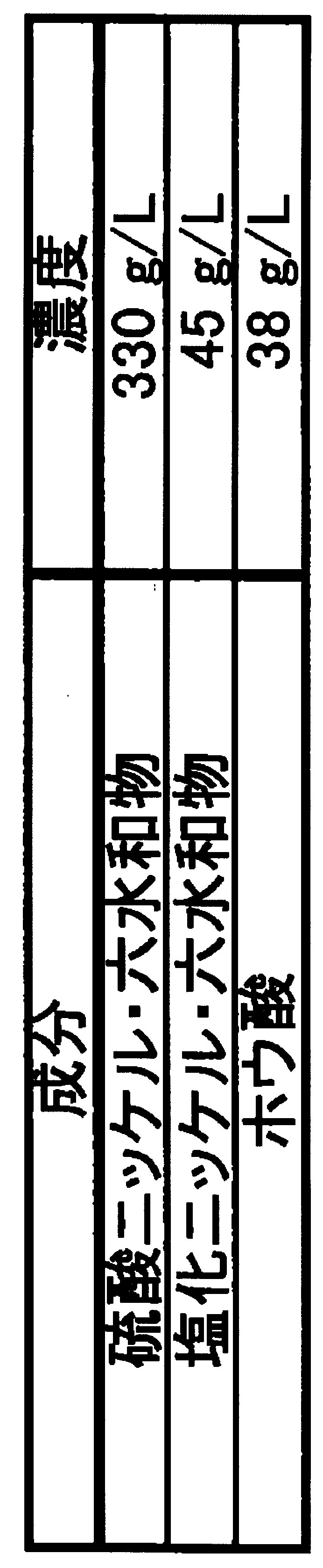
- the Ni plating step the Watt bath having the composition shown in Table 2, the bath temperature is 60 ° C., the current density is 10 A / dm 2 , and the Ni-plated layer is electrolyzed to the outside of the steel plate container. It formed in the surface (1st surface) which becomes. Also, in all Examples and Comparative Examples, Ni plating was performed at the same timing as plating on the outer surface of the container so that the Ni amount was 8.9 g / m 2 on the inner surface of the container.
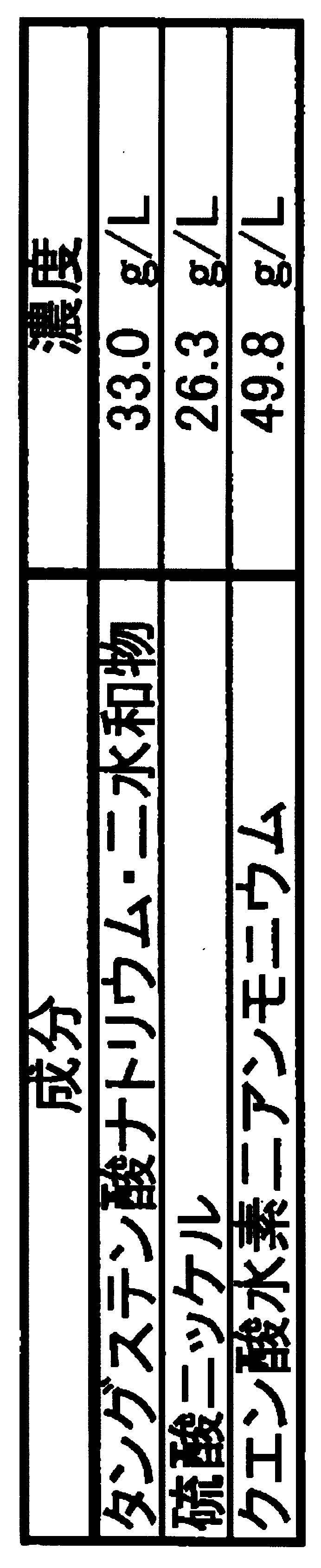
- Ni—W alloy plating step a plating bath having the composition shown in Table 3 was used, the bath temperature was set to 60 ° C., and the Ni—W alloy plating layer was electrolyzed on the surface (first surface) on the outside of the steel plate container. Formed.
- the formed plating composition has current density dependency.
- a Ni-W alloy plating layer having a high W concentration can be formed by setting a low current density, and a Ni-W alloy plating layer having a low W concentration can be formed by plating at a high current density.
- the composition of the formed Ni—W alloy plating layer was changed by changing the current density in the range of 1 A / dm 2 to 50 A / dm 2 .
- cathode electrolysis was performed as a pretreatment for plating at 100 g / L in sulfuric acid at 40 ° C. for 5 seconds at a current density of 5 A / dm 2 .
- the Ni-W alloy plating process is continuously performed after the Ni plating process, the Ni-W is washed before the surface of the steel sheet is dried after the Ni plating process, and before the washing water is dried. It was immersed in a plating solution in the alloy plating process and electroplated.
- Ni-containing layer having an Fe—Ni diffusion alloy layer or a recrystallized Ni layer was formed in 2 atmospheres with a maximum temperature of 650 ° C. and a residence time in the furnace of 20 sec.
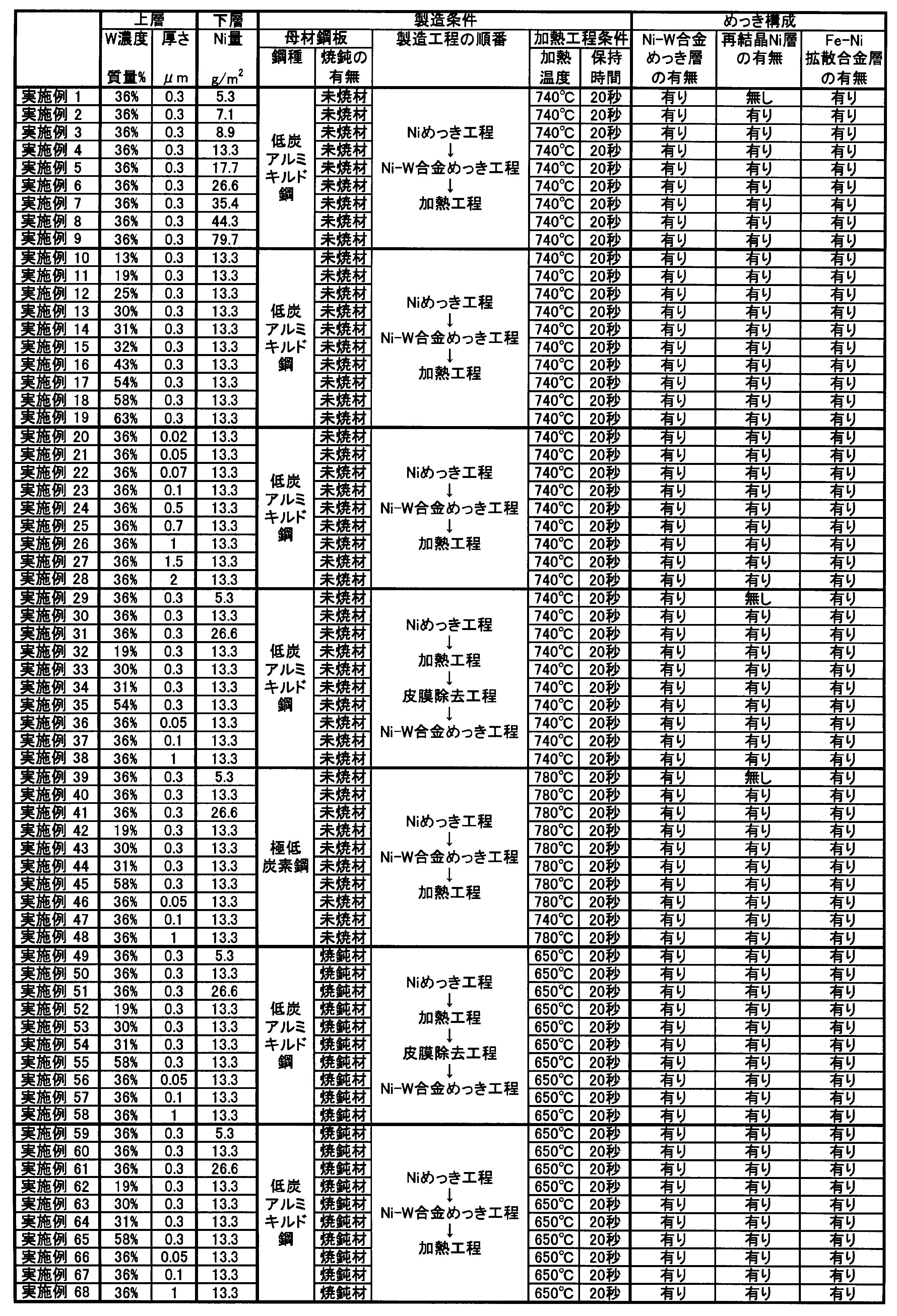
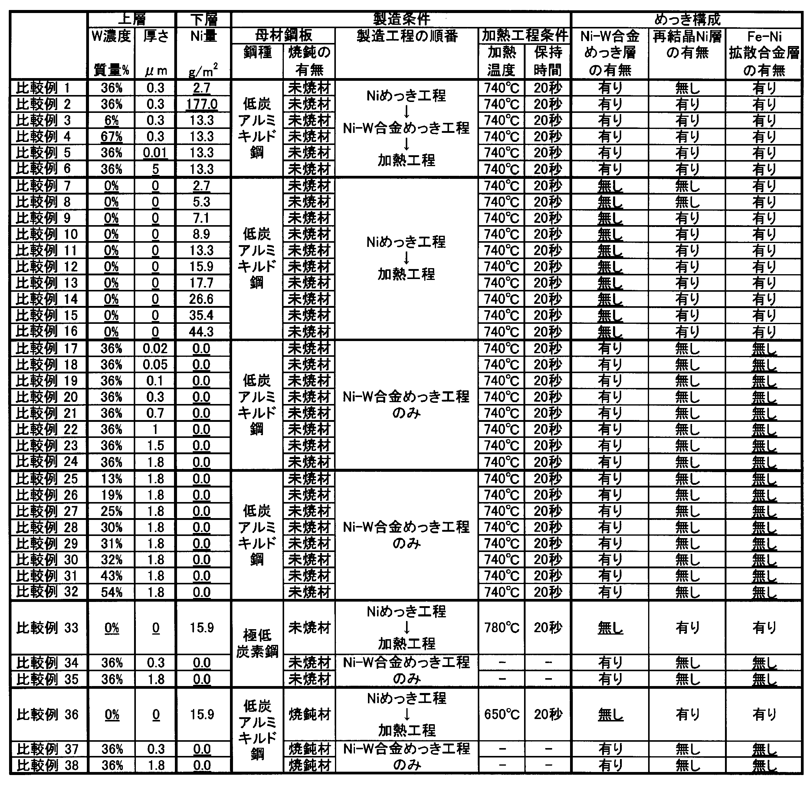
- Ni-containing surface-treated steel sheets for containers of Examples 1 to 68 shown in Table 4 and Comparative Examples 1 to 38 shown in Table 5 were produced.
- the upper layer means a Ni—W alloy plating layer
- the lower layer means a Ni—containing layer having a Fe—Ni diffusion alloy layer or a recrystallized Ni layer.
- underlined data indicates that it is outside the scope of the present invention.
- the Ni-containing surface-treated steel sheet for containers thus prepared was evaluated by the following continuous pressability in cylindrical drawing, corrosion resistance after cylindrical drawing, and slidability at high surface pressure.
- Table 6 shows the evaluation results of Examples 1 to 68
- Table 7 shows the evaluation results of Comparative Examples 1 to 38.
- underlined data indicates that it is outside the scope of the present invention.
- the cylindrical drawing process was performed by multi-stage press molding in which one process is five stages. Specifically, a sample was punched out with a blank diameter of 52 mm ⁇ , and was squeezed to a height of 36 mm and a diameter of 16 mm up to the fourth stage so that the height was 40 mm at the fifth stage.
- Evaluation of continuous pressability in cylindrical drawing was performed by performing the above-mentioned multi-stage press molding in which one process consists of five stages, using five samples under the same conditions, and continuously performing press molding of five processes. . Then, it was confirmed whether all the five samples could be molded up to the final stage (fifth stage) or whether the sample broke along the way.
- 5 presses were continuously performed under the same conditions, even if there was adhesion of the plated metal to the press mold, it was not removed.
- After performing the continuous press of 5 processes within the same conditions if there was adhesion of the plating metal to the press die, it was removed.
- the evaluation criteria for continuous pressability are “B (Bad)” in the table as acceptable when all five samples are press-molded up to the final stage (fifth stage) and rejected when not press-molded. It showed.
- B (Bad) in the table as acceptable when all five samples are press-molded up to the final stage (fifth stage) and rejected when not press-molded. It showed.
- the sliding resistance during press molding is small, which means that there is little adhesion of the plating layer metal to the press mold. In other words, it can be said that the material has excellent continuous pressability.
- B (Bad) was indicated in the table when metal powder was observed on the surface of the press product after press molding.
- Corrosion resistance was evaluated using the press product after press molding only when the evaluation of continuous pressability was acceptable.
- a press product press-molded in the first processing out of all five samples was selected and tested.
- the test conditions for the corrosion resistance evaluation were maintained at a relative humidity of 95% and a temperature of 60 ° C., and the presence or absence of red rust was visually confirmed on the 5th, 10th and 20th days.
- the evaluation criteria are shown as “B (Bad)” in the table as acceptable when red rust does not rust on the fifth day and rejected when red rust is rusted.
- the evaluation of the slidability was judged by the increase rate of the 2 ⁇ average value between the sliding distances of 80 mm and 90 mm with respect to the 2 ⁇ average value between the sliding distances of 20 mm and 30 mm.
- An increase of 2 ⁇ between the sliding distances of 80 mm and 90 mm with respect to 2 ⁇ between the sliding distances of 20 mm and 30 mm means that the plating metal adheres to the mold and the resistance increases.
- the above increase rate of 2 ⁇ the case of 7% or less was regarded as acceptable. In this pass, if the rate of increase is 3% or less, it is “GG (Greatly Good)”. If it is more than 3% and 5% or less, it is “VG (Very Good)”. G (Good) "in the table. And the case of over 7% was shown as “B (Bad)” in the table as a failure.
- the continuous pressability and slidability are such that the thickness of the Ni—W alloy plating layer is thicker up to 2 ⁇ m, and the W concentration in the Ni—W alloy plating layer is up to 65% by mass. The higher the value, the better the performance. Specifically, when the W concentration in the Ni—W alloy plating layer is less than 15% as in Example 10, or when the thickness of the Ni—W alloy plating layer is less than 0.05 ⁇ m as in Example 20.
- the continuous pressability and slidability were “G (Good)”.
- Corrosion resistance showed better performance as the amount of Ni contained in the Ni-containing layer having the Fe—Ni diffusion alloy layer or the recrystallized Ni layer increased.
- a steel plate that is a base material even if the Ni concentration in the Ni—W alloy plating layer is the same as the W concentration and the thickness, and the Ni content in the Ni-containing layer having the Fe—Ni diffusion alloy layer or the recrystallized Ni layer is the same.
- Corrosion resistance was different depending on the presence or absence of annealing. Specifically, as in Examples 1, 29, and 39, an unannealed material was used for the steel plate as the base material, and the steel plate was annealed in the heating process, and the Fe—Ni diffusion alloy layer was formed at a high temperature.
- the case where it was formed and the recrystallized Ni layer was not left in the Ni-containing layer was “G (Good)”.
- the annealed material was used for the steel plate as the base material, and the Fe—Ni diffusion alloy layer was formed at a low temperature, thereby making the Fe—Ni diffusion alloy layer too thick.
- the case where the recrystallized Ni layer was left in the Ni-containing layer was “VG (Very Good)”. This is because the recrystallized Ni layer is softer than the Fe—Ni diffusion alloy layer, so that the effect of suppressing the propagation of cracks entering the Ni—W alloy plating is high.
- the Ni-containing layer did not have a recrystallized Ni layer, the Ni content in the Ni-containing layer including the Fe—Ni diffusion alloy layer was less than 5 g / m 2 , and the corrosion resistance was unacceptable. This is because the cracks that have entered the Ni—W alloy plating layer have penetrated through the Ni-containing layer including the Fe—Ni diffusion alloy layer and have reached the steel plate as the base material.
- the amount of Ni contained in the Ni-containing layer having the Fe—Ni diffusion alloy layer and the recrystallized Ni layer exceeded 89 g / m 2 , the amount of Ni was extremely large, and the continuous pressability and slidability were high. I failed.
- the thickness of the Ni—W alloy plating layer was 0.02 ⁇ m or less, and the continuous pressability and slidability were unacceptable. This is because the Ni-W alloy plating layer was too thin and the underlying recrystallized Ni layer was exposed and adhered to the surface.
- the thickness of the Ni—W alloy plating layer greatly exceeded 2 ⁇ m, and all five samples could be press-molded. However, metal powder was observed on the surface, and the continuous pressability was not acceptable. This is because powdering occurred because the hard Ni—W alloy plating layer was too thick.
- Comparative Example 7-16, 33, and 36 did not have a Ni—W alloy plating layer, the continuous pressability was unacceptable in the above Comparative Examples other than Comparative Example 7. This is because the Ni-containing layer having the Fe—Ni diffusion alloy layer or the recrystallized Ni layer adhered to the mold. Only Comparative Example 7 passed the continuous pressability, but failed the corrosion resistance. In Comparative Example 7, the amount of Ni in the Ni-containing layer having the Fe—Ni diffusion alloy layer was small, and a relatively hard Ni-containing layer having a Fe—Ni diffusion alloy layer with a high Fe concentration was formed by the heating process. The adhesion to the mold was difficult to occur.
- Comparative Example 7 the Fe-Ni diffusion alloy layer included in the Ni-containing layer had a high Fe concentration, and thus the corrosion resistance was unacceptable. All of the comparative examples 17 to 32, 34, 35, 37, and 38 that did not have the Fe-Ni diffusion alloy layer or the Ni-containing layer having the recrystallized Ni layer failed the corrosion resistance. This is because cracks have occurred in the Ni—W alloy plating layer, there is no layer to suppress the propagation, and the cracks have reached the steel plate as the base material.
- Ni—W alloy plating layer Fe—Ni diffusion alloy layer (Ni-containing layer) 3 Steel plate 4 Recrystallized Ni layer (Ni-containing layer) 5 containers
Landscapes
- Chemical & Material Sciences (AREA)
- Chemical Kinetics & Catalysis (AREA)
- Electrochemistry (AREA)
- Engineering & Computer Science (AREA)
- Materials Engineering (AREA)
- Metallurgy (AREA)
- Organic Chemistry (AREA)
- General Chemical & Material Sciences (AREA)
- Inorganic Chemistry (AREA)
- Mechanical Engineering (AREA)
- Electroplating Methods And Accessories (AREA)
Abstract
Description
本願は、2011年4月7日に、日本国に出願された特願2011-085360号に基づき優先権を主張し、その内容をここに援用する。
(1)本発明の一態様にかかるプレス成型によって成型される容器用Ni含有表面処理鋼板は、前記プレス成型後に前記容器の外側となる第1面を有する鋼板と、前記鋼板の前記第1面上に配されたNi含有層と、前記Ni含有層上に配されたNi-W合金めっき層と、を備え:前記Ni含有層がFe-Ni拡散合金層を有し、前記Ni含有層中に含まれるNi量が5g/m2以上89g/m2以下であり;前記Ni-W合金めっき層の厚みが0.02μm以上2μm以下であり;前記Ni-W合金めっき層中のW濃度が、質量%で、10%以上65%以下である。
(2)上記(1)に記載の容器用Ni含有表面処理鋼板では、前記Ni含有層が再結晶Ni層をさらに有し、前記再結晶Ni層が前記Fe-Ni拡散合金層と前記Ni-W合金めっき層との間に配されてもよい。
(3)上記(1)または(2)に記載の容器用Ni含有表面処理鋼板では、前記Ni-W合金めっき層の前記厚みが0.05μm以上1μm以下であり;前記Ni-W合金めっき層中の前記W濃度が、質量%で、15%以上60%以下であってもよい。
(4)上記(1)~(3)の何れか1項に記載の容器用Ni含有表面処理鋼板では、前記Ni-W合金めっき層中の前記W濃度が、質量%で、31%以上55%以下であってもよい。
(5)上記(1)~(4)の何れか1項に記載の容器用Ni含有表面処理鋼板では、前記Ni含有層中に含まれる前記Ni量が、7g/m2以上40g/m2以下であってもよい。
(6)本発明の一態様にかかる容器は、上記(1)~(5)の何れか1項に記載の容器用Ni含有表面処理鋼板によって形成される。
(7)本発明の一態様にかかる上記(1)~(5)の何れか1項に記載の容器用Ni含有表面処理鋼板の製造方法は:前記鋼板の前記第1面側にNiめっきを施すNiめっき工程と;前記鋼板の前記第1面側にNi-W合金めっきを施すNi-W合金めっき工程と;前記Niめっき工程後、または、前記Ni-W合金めっき工程後に、前記鋼板を600℃以上950℃以下の温度範囲で5秒以上60分以下の加熱を行う加熱工程と;を有する。
(8)上記(7)に記載の容器用Ni含有表面処理鋼板の製造方法では、前記加熱工程が前記Niめっき工程後に行われ、前記加熱工程後で前記Ni-W合金めっき工程前に、前記鋼板の前記第1面側の表面の酸化皮膜を除去する皮膜除去工程をさらに有してもよい。
(9)上記(7)に記載の容器用Ni含有表面処理鋼板の製造方法では、前記加熱工程が前記Ni-W合金めっき工程後に行われ、前記Niめっき工程から前記Ni-W合金めっき工程まで間、前記鋼板の前記第1面側が酸化しないように保持してもよい。
(10)上記(7)~(9)の何れか1項に記載の容器用Ni含有表面処理鋼板の製造方法では、前記Niめっき工程で用いる前記鋼板が、冷間圧延により製造され、前記冷間圧延後に未焼鈍であってもよい。
(1)プレス成型によって成型される上記態様の容器用Ni含有表面処理鋼板は、プレス成型後に容器の外側となる第1面を有する鋼板3と、鋼板3の第1面上に配されたFe-Ni拡散合金層2を有するNi含有層と、このNi含有層上に配されたNi-W合金めっき層1と、を備え:Fe-Ni拡散合金層2を有する上記Ni含有層中に含まれるNi量が5g/m2以上89g/m2以下であり;Ni-W合金めっき層1の厚みが0.02μm以上2μm以下であり;Ni-W合金めっき層1中のW濃度が、質量%で、10%以上65%以下である。
(2)そして、上記Ni含有層が再結晶Ni層4をさらに有し、再結晶Ni層4がFe-Ni拡散合金層2とNi-W合金めっき層1との間に配されることが好ましい。
(4)そして、Ni-W合金めっき層1中のW濃度が、質量%で、31%以上55%以下であることが好ましい。
(5)そして、上記Ni含有層中に含まれるNi量が、7g/m2以上40g/m2以下であることが好ましい。
(6)そして、上記態様の容器は、上記(1)~(6)の何れか1項に記載の容器用Ni含有表面処理鋼板によって形成される。
(7)本発明の一態様にかかる上記容器用Ni含有表面処理鋼板の製造方法は:鋼板3の第1面側にNiめっきを施すNiめっき工程と;鋼板3の第1面側にNi-W合金めっきを施すNi-W合金めっき工程と;Niめっき工程後、または、Ni-W合金めっき工程後に、鋼板3を600℃以上950℃以下の温度範囲で5秒以上60分以下の加熱を行う加熱工程と;を有する。
(8)そして、前記加熱工程が前記Niめっき工程後に行われ、前記加熱工程後で前記Ni-W合金めっき工程前に、鋼板3の第1面側の表面の酸化皮膜を除去する皮膜除去工程と;をさらに有してもよい。
(9)または、前記加熱工程が前記Ni-W合金めっき工程後に行われ、前記Niめっき工程から前記Ni-W合金めっき工程まで間、前記鋼板の前記第1面側が酸化しないように保持にしてもよい。
(10)そして、前記Niめっき工程で用いる鋼板3が、冷間圧延により製造され、冷間圧延後に未焼鈍であることが好ましい。
(12)そして、Ni-W合金めっき工程でW濃度が質量%で15%以上60%以下、厚みが0.05μm以上1μm以下となるように電気めっきによりNi-W合金めっきを施すことが好ましい。
(13)そして、Ni-W合金めっき工程でW濃度が質量%で31%以上55%以下、厚みが0.05μm以上1μm以下となるように電気めっきによりNi-W合金めっきを施すことが好ましい。
(14)そして、Niめっき工程でNi量が7g/m2以上40g/m2以下となるように電気めっきによりNiめっきを施すことが好ましい。
表1に成分を示す低炭アルミキルド鋼及びNb-Ti-sulc鋼の冷間圧延鋼板をめっきのための母材である鋼板として用いた。板厚はいずれも0.3mmである。Niめっき工程前に鋼板の焼鈍を行う場合、Niめっき工程後に加熱工程を行う場合、または、Ni-W合金めっき工程後に加熱工程を行う場合の何れの場合も、2%H2-N2雰囲気中で加熱を行った。その際、低炭アルミキルド鋼は740℃で20秒保持し、そして、Nb-Ti-sulc鋼は780℃で20秒保持した。

Niめっき工程では、表2に示した組成のワット浴で、浴温を60℃、電流密度を10A/dm2として、電解によりNiめっきまま層を、鋼板の容器の外側となる面(第1面)に形成した。また、いずれの実施例及び比較例も、容器の内側となる面にNi量が8.9g/m2となるように、容器の外側となる面にめっきするのと同じタイミングでNiめっきした。Ni-W合金めっき工程では、表3に示した組成のめっき浴で、浴温を60℃として、電解によりNi-W合金めっき層を、鋼板の容器の外側となる面(第1面)に形成した。表3に示すめっき浴を用いる場合、形成されるめっき組成は、電流密度依存性を有する。低電流密度にすることで高W濃度のNi-W合金めっき層を、高電流密度でめっきすることで低W濃度のNi-W合金めっき層を形成できる。ここでは、1A/dm2から50A/dm2の範囲で電流密度を変化させることで、形成されるNi-W合金めっき層の組成を変化させた。また、Niめっき工程及びNi-W合金めっき工程ともに、めっきの前処理として、100g/Lで40℃の硫酸中で、電流密度5A/dm2で5秒間のカソード電解を行った。ただし、Niめっき工程後、Ni-W合金めっき工程を連続して実施する場合は、Niめっき工程後、鋼板の表面が乾かないうちに水洗し、そして、水洗水が乾かないうちにNi-W合金めっき工程のめっき液に浸漬して電解めっきした。
Niめっき工程で未焼鈍の鋼板を用いた場合、加熱工程として、鋼板の焼鈍を行うと同時に、Fe-Ni拡散合金層または再結晶Ni層を有するNi含有層を形成した。この際、2%H2-N2雰囲気中で、低炭アルミキルド鋼は740℃で20秒保持し、そして、Nb-Ti-sulc鋼は780℃で20秒保持した。Niめっき工程で焼鈍後の鋼板を用いた場合、母材である鋼板の材質への影響を考慮し、加熱工程として、低炭アルミキルド鋼及びNb-Ti-sulc鋼ともに、2%H2-N2雰囲気中で、最高到達温度650℃で炉内滞在時間を20secとして、Fe-Ni拡散合金層または再結晶Ni層を有するNi含有層を形成した。

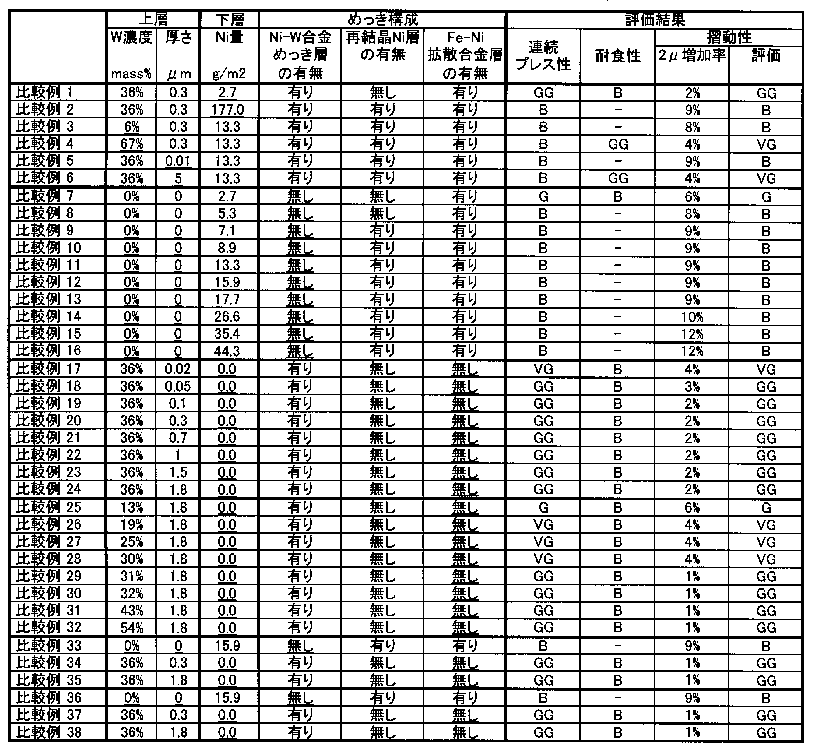
比較例2はFe-Ni拡散合金層及び再結晶Ni層を有するNi含有層中に含まれるNi量が89g/m2を超え、このNi量が極端に多く、連続プレス性及び摺動性が不合格だった。これは、Ni-W合金めっき層のクラックから再結晶Ni層が露出し、金型に凝着してしまったためである。
比較例3はNi-W合金めっき層中のW濃度が質量%で10%未満であり、連続プレス性及び摺動性が不合格だった。これは、Ni-W合金めっき層中のW濃度が低かったため、Ni-W合金めっきの硬度が低く、金型に凝着してしまったためである。
比較例4は、Ni-W合金めっき層中のW濃度が質量%で65%を超えており、5個全てのサンプルをプレス成型できたが、表面に金属粉が認められ、連続プレス性が不合格だった。これは、めっき層が硬質過ぎて、パウダリングが発生したためである。
比較例5はNi-W合金めっき層の厚みが0.02μm以下であり、連続プレス性及び摺動性が不合格だった。これは、Ni-W合金めっき層が薄すぎたため、下地の再結晶Ni層が表面に露出し、凝着したためである。
比較例6はNi-W合金めっき層の厚みが2μmを大きく超えており、5個全てのサンプルをプレス成型できたが、表面に金属粉が認められ、連続プレス性が不合格だった。これは、硬質なNi-W合金めっき層が厚すぎて、パウダリングが発生したためである。
比較例17~32、34、35、37、及び、38のようにFe-Ni拡散合金層または再結晶Ni層を有するNi含有層を有さないものは、全て耐食性が不合格だった。これは、Ni-W合金めっき層にクラックが入り、その伝播を抑制する層が無く、母材である鋼板までクラックが到達してしまったためである。
2 Fe-Ni拡散合金層(Ni含有層)
3 鋼板
4 再結晶Ni層(Ni含有層)
5 容器
Claims (10)
- プレス成型によって成型される容器用Ni含有表面処理鋼板であって、
前記プレス成型後に前記容器の外側となる第1面を有する鋼板と、前記鋼板の前記第1面上に配されたNi含有層と、前記Ni含有層上に配されたNi-W合金めっき層と、を備え:
前記Ni含有層がFe-Ni拡散合金層を有し、前記Ni含有層中に含まれるNi量が5g/m2以上89g/m2以下であり;
前記Ni-W合金めっき層の厚みが0.02μm以上2μm以下であり;
前記Ni-W合金めっき層中のW濃度が、質量%で、10%以上65%以下である;
ことを特徴とする容器用Ni含有表面処理鋼板。 - 前記Ni含有層が再結晶Ni層をさらに有し、前記再結晶Ni層が前記Fe-Ni拡散合金層と前記Ni-W合金めっき層との間に配されることを特徴とする請求項1に記載の容器用Ni含有表面処理鋼板。
- 前記Ni-W合金めっき層の前記厚みが0.05μm以上1μm以下であり;
前記Ni-W合金めっき層中の前記W濃度が、質量%で、15%以上60%以下である;
ことを特徴とする請求項1または2に記載の容器用Ni含有表面処理鋼板。 - 前記Ni-W合金めっき層中の前記W濃度が、質量%で、31%以上55%以下であることを特徴とする請求項3に記載の容器用Ni含有表面処理鋼板。
- 前記Ni含有層中に含まれる前記Ni量が、7g/m2以上40g/m2以下であることを特徴とする請求項1または2に記載の容器用Ni含有表面処理鋼板。
- 請求項1または2に記載の容器用Ni含有表面処理鋼板によって形成されることを特徴とする容器。
- 請求項1または2に記載の容器用Ni含有表面処理鋼板の製造方法であって:
前記鋼板の前記第1面側にNiめっきを施すNiめっき工程と;
前記鋼板の前記第1面側にNi-W合金めっきを施すNi-W合金めっき工程と;
前記Niめっき工程後、または、前記Ni-W合金めっき工程後に、前記鋼板を600℃以上950℃以下の温度範囲で5秒以上60分以下の加熱を行う加熱工程と;を有する
ことを特徴とする容器用Ni含有表面処理鋼板の製造方法。 - 前記加熱工程が前記Niめっき工程後に行われ、
前記加熱工程後で前記Ni-W合金めっき工程前に、前記鋼板の前記第1面側の表面の酸化皮膜を除去する皮膜除去工程をさらに有する
ことを特徴とする請求項7に記載の容器用Ni含有表面処理鋼板の製造方法。 - 前記加熱工程が前記Ni-W合金めっき工程後に行われ、
前記Niめっき工程から前記Ni-W合金めっき工程まで間、前記鋼板の前記第1面側が酸化しないように保持する
ことを特徴とする請求項7に記載の容器用Ni含有表面処理鋼板の製造方法。 - 前記Niめっき工程で用いる前記鋼板が、冷間圧延により製造され、前記冷間圧延後に未焼鈍であることを特徴とする請求項7に記載の容器用Ni含有表面処理鋼板の製造方法。
Priority Applications (4)
| Application Number | Priority Date | Filing Date | Title |
|---|---|---|---|
| JP2013508899A JP5447734B2 (ja) | 2011-04-07 | 2012-04-04 | 容器用Ni含有表面処理鋼板および容器 |
| CN201280016827.0A CN103476971B (zh) | 2011-04-07 | 2012-04-04 | 容器用含Ni表面处理钢板及其制造方法 |
| KR1020137025746A KR101597406B1 (ko) | 2011-04-07 | 2012-04-04 | 용기용 Ni 함유 표면 처리 강판 및 그 제조 방법 |
| US14/009,377 US9132610B2 (en) | 2011-04-07 | 2012-04-04 | Ni-containing-surface-treated steel sheet for can and manufacturing method thereof |
Applications Claiming Priority (2)
| Application Number | Priority Date | Filing Date | Title |
|---|---|---|---|
| JP2011085360 | 2011-04-07 | ||
| JP2011-085360 | 2011-04-07 |
Publications (1)
| Publication Number | Publication Date |
|---|---|
| WO2012137823A1 true WO2012137823A1 (ja) | 2012-10-11 |
Family
ID=46969217
Family Applications (1)
| Application Number | Title | Priority Date | Filing Date |
|---|---|---|---|
| PCT/JP2012/059204 Ceased WO2012137823A1 (ja) | 2011-04-07 | 2012-04-04 | 容器用Ni含有表面処理鋼板およびその製造方法 |
Country Status (6)
| Country | Link |
|---|---|
| US (1) | US9132610B2 (ja) |
| JP (1) | JP5447734B2 (ja) |
| KR (1) | KR101597406B1 (ja) |
| CN (1) | CN103476971B (ja) |
| TW (1) | TWI451005B (ja) |
| WO (1) | WO2012137823A1 (ja) |
Cited By (6)
| Publication number | Priority date | Publication date | Assignee | Title |
|---|---|---|---|---|
| JP2018135563A (ja) * | 2017-02-22 | 2018-08-30 | 株式会社太洋工作所 | 構造体およびその製造方法 |
| JP2022013058A (ja) * | 2020-07-03 | 2022-01-18 | Fdk株式会社 | 電池 |
| WO2022215634A1 (ja) | 2021-04-08 | 2022-10-13 | 日本製鉄株式会社 | 表面処理鋼板 |
| WO2024166934A1 (ja) | 2023-02-07 | 2024-08-15 | 日本製鉄株式会社 | 表面処理鋼板 |
| WO2024166933A1 (ja) | 2023-02-07 | 2024-08-15 | 日本製鉄株式会社 | 表面処理鋼板、及び表面処理鋼板の製造方法 |
| JP7640927B1 (ja) * | 2024-02-07 | 2025-03-06 | 日本製鉄株式会社 | 表面処理鋼板、表面処理鋼板の製造方法、及び電池部品の製造方法 |
Families Citing this family (8)
| Publication number | Priority date | Publication date | Assignee | Title |
|---|---|---|---|---|
| JP6706464B2 (ja) * | 2015-03-31 | 2020-06-10 | Fdk株式会社 | 電池缶形成用鋼板、及びアルカリ電池 |
| EP3385411A4 (en) * | 2015-12-03 | 2019-04-17 | Toyo Kohan Co., Ltd. | SURFACE TREATED STEEL PLATE FOR BATTERY TANK |
| KR102402639B1 (ko) | 2017-11-24 | 2022-05-26 | 삼성전자주식회사 | 전자 장치 및 그의 통신 방법 |
| CN111971419B (zh) * | 2018-04-13 | 2024-03-29 | 日本制铁株式会社 | Ni扩散镀层钢板以及Ni扩散镀层钢板的制造方法 |
| CN111989424B (zh) * | 2018-04-13 | 2024-04-23 | 日本制铁株式会社 | Ni扩散镀层钢板以及Ni扩散镀层钢板的制造方法 |
| CN113166966B (zh) * | 2018-12-27 | 2024-09-27 | 日本制铁株式会社 | 加工后耐腐蚀性优异的镀镍钢板及镀镍钢板的制造方法 |
| CN111411383B (zh) * | 2020-03-31 | 2021-10-29 | 上海天马微电子有限公司 | 一种不锈钢箔的加工方法、不锈钢箔及柔性显示装置 |
| KR102827994B1 (ko) * | 2024-11-26 | 2025-07-03 | 주식회사 티씨씨스틸 | 내식성이 우수한 전지 케이스용 니켈 도금강판 및 이의 제조방법 |
Citations (5)
| Publication number | Priority date | Publication date | Assignee | Title |
|---|---|---|---|---|
| WO1995011527A1 (fr) * | 1993-10-22 | 1995-04-27 | Toyo Kohan Co., Ltd. | Feuille d'acier traite en surface pour boitier de batterie et boitier de batterie produit a l'aide de ladite feuille |
| JPH09306439A (ja) * | 1996-05-21 | 1997-11-28 | Katayama Tokushu Kogyo Kk | 電池缶形成材料、電池缶形成方法および電池缶 |
| WO2000065671A1 (fr) * | 1999-04-22 | 2000-11-02 | Toyo Kohan Co., Ltd. | Enveloppe de pile et feuille d'acier traitee en surface pour enveloppe de pile |
| JP2005149735A (ja) * | 2003-11-11 | 2005-06-09 | Nippon Steel Corp | 電池缶用Niメッキ鋼板 |
| JP2007051325A (ja) * | 2005-08-17 | 2007-03-01 | Toyo Kohan Co Ltd | 電池容器用めっき鋼板、その電池容器用めっき鋼板を用いた電池容器、およびその電池容器を用いた電池 |
Family Cites Families (14)
| Publication number | Priority date | Publication date | Assignee | Title |
|---|---|---|---|---|
| JPH01111896A (ja) | 1987-10-27 | 1989-04-28 | Nippon Steel Corp | ステンレス鋼板の表面処理法 |
| JPH0285394A (ja) | 1988-09-22 | 1990-03-26 | Nippon Steel Corp | ステンレス鋼板の電気めっき方法 |
| JP3045612B2 (ja) * | 1992-06-22 | 2000-05-29 | 東洋鋼鈑株式会社 | 高耐食性ニッケルめっき鋼帯およびその製造法 |
| JPH06293978A (ja) | 1993-04-07 | 1994-10-21 | Nippon Steel Corp | 耐食性、深絞り性およびはんだ性に優れた自動車燃料タンク用複層冷延鋼板 |
| US5413874A (en) * | 1994-06-02 | 1995-05-09 | Baldwin Hardware Corporation | Article having a decorative and protective multilayer coating simulating brass |
| JP4808834B2 (ja) | 2000-08-04 | 2011-11-02 | 東洋鋼鈑株式会社 | 電池ケース用表面処理鋼板 |
| JP3854464B2 (ja) * | 2001-01-09 | 2006-12-06 | 新日本製鐵株式会社 | アルカリマンガン電池正極缶用Niメッキ鋼板 |
| JP2005146405A (ja) * | 2003-11-14 | 2005-06-09 | Toru Yamazaki | 電析積層合金薄板とその製造方法 |
| JP3985904B2 (ja) | 2004-09-13 | 2007-10-03 | 株式会社黄金メッキ工場 | ニッケル−タングステン合金めっき液及びニッケル−タングステン合金めっき皮膜の形成方法 |
| JP4824961B2 (ja) * | 2005-07-22 | 2011-11-30 | 東洋鋼鈑株式会社 | 電池容器用めっき鋼板、その電池容器用めっき鋼板を用いた電池容器、およびその電池容器を用いた電池 |
| JP4864426B2 (ja) * | 2005-11-15 | 2012-02-01 | 新日本製鐵株式会社 | 鉄系合金の半溶融・半凝固鋳造用の金型 |
| US20090286103A1 (en) * | 2008-05-14 | 2009-11-19 | Xtalic Corporation | Coated articles and related methods |
| AU2010230280B2 (en) | 2009-03-30 | 2013-08-29 | Shell Internationale Research Maatschappij B.V. | Process for producing a purified synthesis gas stream |
| JP5280957B2 (ja) | 2009-07-28 | 2013-09-04 | 三菱伸銅株式会社 | 導電部材及びその製造方法 |
-
2012
- 2012-04-03 TW TW101111837A patent/TWI451005B/zh active
- 2012-04-04 KR KR1020137025746A patent/KR101597406B1/ko active Active
- 2012-04-04 CN CN201280016827.0A patent/CN103476971B/zh active Active
- 2012-04-04 US US14/009,377 patent/US9132610B2/en active Active
- 2012-04-04 JP JP2013508899A patent/JP5447734B2/ja active Active
- 2012-04-04 WO PCT/JP2012/059204 patent/WO2012137823A1/ja not_active Ceased
Patent Citations (5)
| Publication number | Priority date | Publication date | Assignee | Title |
|---|---|---|---|---|
| WO1995011527A1 (fr) * | 1993-10-22 | 1995-04-27 | Toyo Kohan Co., Ltd. | Feuille d'acier traite en surface pour boitier de batterie et boitier de batterie produit a l'aide de ladite feuille |
| JPH09306439A (ja) * | 1996-05-21 | 1997-11-28 | Katayama Tokushu Kogyo Kk | 電池缶形成材料、電池缶形成方法および電池缶 |
| WO2000065671A1 (fr) * | 1999-04-22 | 2000-11-02 | Toyo Kohan Co., Ltd. | Enveloppe de pile et feuille d'acier traitee en surface pour enveloppe de pile |
| JP2005149735A (ja) * | 2003-11-11 | 2005-06-09 | Nippon Steel Corp | 電池缶用Niメッキ鋼板 |
| JP2007051325A (ja) * | 2005-08-17 | 2007-03-01 | Toyo Kohan Co Ltd | 電池容器用めっき鋼板、その電池容器用めっき鋼板を用いた電池容器、およびその電池容器を用いた電池 |
Cited By (16)
| Publication number | Priority date | Publication date | Assignee | Title |
|---|---|---|---|---|
| JP2018135563A (ja) * | 2017-02-22 | 2018-08-30 | 株式会社太洋工作所 | 構造体およびその製造方法 |
| JP2022013058A (ja) * | 2020-07-03 | 2022-01-18 | Fdk株式会社 | 電池 |
| JP7629279B2 (ja) | 2020-07-03 | 2025-02-13 | Fdk株式会社 | 電池 |
| WO2022215634A1 (ja) | 2021-04-08 | 2022-10-13 | 日本製鉄株式会社 | 表面処理鋼板 |
| JPWO2022215634A1 (ja) * | 2021-04-08 | 2022-10-13 | ||
| KR20230150374A (ko) | 2021-04-08 | 2023-10-30 | 닛폰세이테츠 가부시키가이샤 | 표면 처리 강판 |
| JP7425389B2 (ja) | 2021-04-08 | 2024-01-31 | 日本製鉄株式会社 | 表面処理鋼板 |
| JP7578899B1 (ja) * | 2023-02-07 | 2024-11-07 | 日本製鉄株式会社 | 表面処理鋼板、及び表面処理鋼板の製造方法 |
| WO2024166933A1 (ja) | 2023-02-07 | 2024-08-15 | 日本製鉄株式会社 | 表面処理鋼板、及び表面処理鋼板の製造方法 |
| JP7606151B1 (ja) * | 2023-02-07 | 2024-12-25 | 日本製鉄株式会社 | 表面処理鋼板 |
| WO2024166934A1 (ja) | 2023-02-07 | 2024-08-15 | 日本製鉄株式会社 | 表面処理鋼板 |
| KR20250123906A (ko) | 2023-02-07 | 2025-08-18 | 닛폰세이테츠 가부시키가이샤 | 표면 처리 강판 |
| KR20250126825A (ko) | 2023-02-07 | 2025-08-25 | 닛폰세이테츠 가부시키가이샤 | 표면 처리 강판, 및 표면 처리 강판의 제조 방법 |
| EP4663816A1 (en) | 2023-02-07 | 2025-12-17 | Nippon Steel Corporation | Surface-treated steel sheet and method for manufacturing surface-treated steel sheet |
| JP7640927B1 (ja) * | 2024-02-07 | 2025-03-06 | 日本製鉄株式会社 | 表面処理鋼板、表面処理鋼板の製造方法、及び電池部品の製造方法 |
| WO2025169335A1 (ja) | 2024-02-07 | 2025-08-14 | 日本製鉄株式会社 | 表面処理鋼板、表面処理鋼板の製造方法、及び電池部品の製造方法 |
Also Published As
| Publication number | Publication date |
|---|---|
| KR20130126725A (ko) | 2013-11-20 |
| TW201245503A (en) | 2012-11-16 |
| JPWO2012137823A1 (ja) | 2014-07-28 |
| JP5447734B2 (ja) | 2014-03-19 |
| KR101597406B1 (ko) | 2016-02-24 |
| US9132610B2 (en) | 2015-09-15 |
| CN103476971B (zh) | 2016-01-06 |
| TWI451005B (zh) | 2014-09-01 |
| CN103476971A (zh) | 2013-12-25 |
| US20140017515A1 (en) | 2014-01-16 |
Similar Documents
| Publication | Publication Date | Title |
|---|---|---|
| JP5447734B2 (ja) | 容器用Ni含有表面処理鋼板および容器 | |
| JP5015239B2 (ja) | 缶用めっき鋼板及びその製造方法 | |
| TWI840140B (zh) | 表面處理鋼板及其製造方法 | |
| JP6146541B2 (ja) | めっき鋼板およびその製造方法 | |
| TWI477662B (zh) | 鍍錫鋼板之製造方法及鍍錫鋼板暨化學轉化處理液 | |
| JP4995140B2 (ja) | 容器用Niめっき鋼板とそれにより製造した容器およびその製造方法 | |
| TWI391532B (zh) | A plated steel sheet for use in a tank and a method for manufacturing the same | |
| JP5365335B2 (ja) | 錫めっき鋼板およびその製造方法 | |
| TWI605155B (zh) | 容器用鋼板及容器用鋼板之製造方法 | |
| JP2010018834A (ja) | 錫めっき鋼板およびその製造方法 | |
| JP6079891B2 (ja) | 容器用鋼板 | |
| TW201430146A (zh) | 容器用鋼板及其製造方法 | |
| JP6052305B2 (ja) | 容器用鋼板 | |
| JP6197778B2 (ja) | 容器用鋼板およびその製造方法 | |
| JP6048441B2 (ja) | 容器用鋼板 | |
| JP6135650B2 (ja) | 容器用鋼板 | |
| JP6146402B2 (ja) | 容器用鋼板 | |
| JP6164206B2 (ja) | 容器用鋼板およびその製造方法 | |
| JP4452198B2 (ja) | シーム溶接性に優れた表面処理鋼板 | |
| JP6123847B2 (ja) | 容器用鋼板およびその製造方法 | |
| JP6003553B2 (ja) | 処理液、容器用鋼板、および、容器用鋼板の製造方法 | |
| JP2010255080A (ja) | 錫めっき鋼板およびその製造方法 |
Legal Events
| Date | Code | Title | Description |
|---|---|---|---|
| 121 | Ep: the epo has been informed by wipo that ep was designated in this application |
Ref document number: 12767687 Country of ref document: EP Kind code of ref document: A1 |
|
| ENP | Entry into the national phase |
Ref document number: 2013508899 Country of ref document: JP Kind code of ref document: A |
|
| ENP | Entry into the national phase |
Ref document number: 20137025746 Country of ref document: KR Kind code of ref document: A |
|
| WWE | Wipo information: entry into national phase |
Ref document number: 14009377 Country of ref document: US |
|
| NENP | Non-entry into the national phase |
Ref country code: DE |
|
| 122 | Ep: pct application non-entry in european phase |
Ref document number: 12767687 Country of ref document: EP Kind code of ref document: A1 |