WO2012132639A1 - 金属と熱可塑性樹脂の複合体 - Google Patents
金属と熱可塑性樹脂の複合体 Download PDFInfo
- Publication number
- WO2012132639A1 WO2012132639A1 PCT/JP2012/054091 JP2012054091W WO2012132639A1 WO 2012132639 A1 WO2012132639 A1 WO 2012132639A1 JP 2012054091 W JP2012054091 W JP 2012054091W WO 2012132639 A1 WO2012132639 A1 WO 2012132639A1
- Authority
- WO
- WIPO (PCT)
- Prior art keywords
- composite
- metal
- thermoplastic resin
- polyamide
- mass
- Prior art date
- Legal status (The legal status is an assumption and is not a legal conclusion. Google has not performed a legal analysis and makes no representation as to the accuracy of the status listed.)
- Ceased
Links
Images

Classifications
-
- B—PERFORMING OPERATIONS; TRANSPORTING
- B32—LAYERED PRODUCTS
- B32B—LAYERED PRODUCTS, i.e. PRODUCTS BUILT-UP OF STRATA OF FLAT OR NON-FLAT, e.g. CELLULAR OR HONEYCOMB, FORM
- B32B7/00—Layered products characterised by the relation between layers; Layered products characterised by the relative orientation of features between layers, or by the relative values of a measurable parameter between layers, i.e. products comprising layers having different physical, chemical or physicochemical properties; Layered products characterised by the interconnection of layers
- B32B7/04—Interconnection of layers
-
- B—PERFORMING OPERATIONS; TRANSPORTING
- B29—WORKING OF PLASTICS; WORKING OF SUBSTANCES IN A PLASTIC STATE IN GENERAL
- B29C—SHAPING OR JOINING OF PLASTICS; SHAPING OF MATERIAL IN A PLASTIC STATE, NOT OTHERWISE PROVIDED FOR; AFTER-TREATMENT OF THE SHAPED PRODUCTS, e.g. REPAIRING
- B29C45/00—Injection moulding, i.e. forcing the required volume of moulding material through a nozzle into a closed mould; Apparatus therefor
- B29C45/14—Injection moulding, i.e. forcing the required volume of moulding material through a nozzle into a closed mould; Apparatus therefor incorporating preformed parts or layers, e.g. injection moulding around inserts or for coating articles
- B29C45/14311—Injection moulding, i.e. forcing the required volume of moulding material through a nozzle into a closed mould; Apparatus therefor incorporating preformed parts or layers, e.g. injection moulding around inserts or for coating articles using means for bonding the coating to the articles
-
- B—PERFORMING OPERATIONS; TRANSPORTING
- B29—WORKING OF PLASTICS; WORKING OF SUBSTANCES IN A PLASTIC STATE IN GENERAL
- B29C—SHAPING OR JOINING OF PLASTICS; SHAPING OF MATERIAL IN A PLASTIC STATE, NOT OTHERWISE PROVIDED FOR; AFTER-TREATMENT OF THE SHAPED PRODUCTS, e.g. REPAIRING
- B29C45/00—Injection moulding, i.e. forcing the required volume of moulding material through a nozzle into a closed mould; Apparatus therefor
- B29C45/14—Injection moulding, i.e. forcing the required volume of moulding material through a nozzle into a closed mould; Apparatus therefor incorporating preformed parts or layers, e.g. injection moulding around inserts or for coating articles
- B29C45/14778—Injection moulding, i.e. forcing the required volume of moulding material through a nozzle into a closed mould; Apparatus therefor incorporating preformed parts or layers, e.g. injection moulding around inserts or for coating articles the article consisting of a material with particular properties, e.g. porous, brittle
-
- B—PERFORMING OPERATIONS; TRANSPORTING
- B32—LAYERED PRODUCTS
- B32B—LAYERED PRODUCTS, i.e. PRODUCTS BUILT-UP OF STRATA OF FLAT OR NON-FLAT, e.g. CELLULAR OR HONEYCOMB, FORM
- B32B1/00—Layered products having a non-planar shape
- B32B1/08—Tubular products
-
- B—PERFORMING OPERATIONS; TRANSPORTING
- B32—LAYERED PRODUCTS
- B32B—LAYERED PRODUCTS, i.e. PRODUCTS BUILT-UP OF STRATA OF FLAT OR NON-FLAT, e.g. CELLULAR OR HONEYCOMB, FORM
- B32B15/00—Layered products comprising a layer of metal
- B32B15/04—Layered products comprising a layer of metal comprising metal as the main or only constituent of a layer, which is next to another layer of the same or of a different material
- B32B15/08—Layered products comprising a layer of metal comprising metal as the main or only constituent of a layer, which is next to another layer of the same or of a different material of synthetic resin
-
- B—PERFORMING OPERATIONS; TRANSPORTING
- B32—LAYERED PRODUCTS
- B32B—LAYERED PRODUCTS, i.e. PRODUCTS BUILT-UP OF STRATA OF FLAT OR NON-FLAT, e.g. CELLULAR OR HONEYCOMB, FORM
- B32B15/00—Layered products comprising a layer of metal
- B32B15/04—Layered products comprising a layer of metal comprising metal as the main or only constituent of a layer, which is next to another layer of the same or of a different material
- B32B15/08—Layered products comprising a layer of metal comprising metal as the main or only constituent of a layer, which is next to another layer of the same or of a different material of synthetic resin
- B32B15/088—Layered products comprising a layer of metal comprising metal as the main or only constituent of a layer, which is next to another layer of the same or of a different material of synthetic resin comprising polyamides
-
- B—PERFORMING OPERATIONS; TRANSPORTING
- B32—LAYERED PRODUCTS
- B32B—LAYERED PRODUCTS, i.e. PRODUCTS BUILT-UP OF STRATA OF FLAT OR NON-FLAT, e.g. CELLULAR OR HONEYCOMB, FORM
- B32B15/00—Layered products comprising a layer of metal
- B32B15/18—Layered products comprising a layer of metal comprising iron or steel
-
- B—PERFORMING OPERATIONS; TRANSPORTING
- B32—LAYERED PRODUCTS
- B32B—LAYERED PRODUCTS, i.e. PRODUCTS BUILT-UP OF STRATA OF FLAT OR NON-FLAT, e.g. CELLULAR OR HONEYCOMB, FORM
- B32B15/00—Layered products comprising a layer of metal
- B32B15/20—Layered products comprising a layer of metal comprising aluminium or copper
-
- B—PERFORMING OPERATIONS; TRANSPORTING
- B32—LAYERED PRODUCTS
- B32B—LAYERED PRODUCTS, i.e. PRODUCTS BUILT-UP OF STRATA OF FLAT OR NON-FLAT, e.g. CELLULAR OR HONEYCOMB, FORM
- B32B27/00—Layered products comprising a layer of synthetic resin
- B32B27/18—Layered products comprising a layer of synthetic resin characterised by the use of special additives
- B32B27/20—Layered products comprising a layer of synthetic resin characterised by the use of special additives using fillers, pigments, thixotroping agents
-
- B—PERFORMING OPERATIONS; TRANSPORTING
- B32—LAYERED PRODUCTS
- B32B—LAYERED PRODUCTS, i.e. PRODUCTS BUILT-UP OF STRATA OF FLAT OR NON-FLAT, e.g. CELLULAR OR HONEYCOMB, FORM
- B32B3/00—Layered products comprising a layer with external or internal discontinuities or unevennesses, or a layer of non-planar shape; Layered products comprising a layer having particular features of form
- B32B3/26—Layered products comprising a layer with external or internal discontinuities or unevennesses, or a layer of non-planar shape; Layered products comprising a layer having particular features of form characterised by a particular shape of the outline of the cross-section of a continuous layer; characterised by a layer with cavities or internal voids ; characterised by an apertured layer
- B32B3/266—Layered products comprising a layer with external or internal discontinuities or unevennesses, or a layer of non-planar shape; Layered products comprising a layer having particular features of form characterised by a particular shape of the outline of the cross-section of a continuous layer; characterised by a layer with cavities or internal voids ; characterised by an apertured layer characterised by an apertured layer, the apertures going through the whole thickness of the layer, e.g. expanded metal, perforated layer, slit layer regular cells B32B3/12
-
- B—PERFORMING OPERATIONS; TRANSPORTING
- B32—LAYERED PRODUCTS
- B32B—LAYERED PRODUCTS, i.e. PRODUCTS BUILT-UP OF STRATA OF FLAT OR NON-FLAT, e.g. CELLULAR OR HONEYCOMB, FORM
- B32B3/00—Layered products comprising a layer with external or internal discontinuities or unevennesses, or a layer of non-planar shape; Layered products comprising a layer having particular features of form
- B32B3/26—Layered products comprising a layer with external or internal discontinuities or unevennesses, or a layer of non-planar shape; Layered products comprising a layer having particular features of form characterised by a particular shape of the outline of the cross-section of a continuous layer; characterised by a layer with cavities or internal voids ; characterised by an apertured layer
- B32B3/30—Layered products comprising a layer with external or internal discontinuities or unevennesses, or a layer of non-planar shape; Layered products comprising a layer having particular features of form characterised by a particular shape of the outline of the cross-section of a continuous layer; characterised by a layer with cavities or internal voids ; characterised by an apertured layer characterised by a layer formed with recesses or projections, e.g. hollows, grooves, protuberances, ribs
-
- B—PERFORMING OPERATIONS; TRANSPORTING
- B29—WORKING OF PLASTICS; WORKING OF SUBSTANCES IN A PLASTIC STATE IN GENERAL
- B29C—SHAPING OR JOINING OF PLASTICS; SHAPING OF MATERIAL IN A PLASTIC STATE, NOT OTHERWISE PROVIDED FOR; AFTER-TREATMENT OF THE SHAPED PRODUCTS, e.g. REPAIRING
- B29C45/00—Injection moulding, i.e. forcing the required volume of moulding material through a nozzle into a closed mould; Apparatus therefor
- B29C45/14—Injection moulding, i.e. forcing the required volume of moulding material through a nozzle into a closed mould; Apparatus therefor incorporating preformed parts or layers, e.g. injection moulding around inserts or for coating articles
- B29C2045/1486—Details, accessories and auxiliary operations
- B29C2045/14868—Pretreatment of the insert, e.g. etching, cleaning
-
- B—PERFORMING OPERATIONS; TRANSPORTING
- B29—WORKING OF PLASTICS; WORKING OF SUBSTANCES IN A PLASTIC STATE IN GENERAL
- B29C—SHAPING OR JOINING OF PLASTICS; SHAPING OF MATERIAL IN A PLASTIC STATE, NOT OTHERWISE PROVIDED FOR; AFTER-TREATMENT OF THE SHAPED PRODUCTS, e.g. REPAIRING
- B29C45/00—Injection moulding, i.e. forcing the required volume of moulding material through a nozzle into a closed mould; Apparatus therefor
- B29C45/14—Injection moulding, i.e. forcing the required volume of moulding material through a nozzle into a closed mould; Apparatus therefor incorporating preformed parts or layers, e.g. injection moulding around inserts or for coating articles
- B29C2045/1486—Details, accessories and auxiliary operations
- B29C2045/14868—Pretreatment of the insert, e.g. etching, cleaning
- B29C2045/14877—Pretreatment of the insert, e.g. etching, cleaning preheating or precooling the insert for non-deforming purposes
-
- B—PERFORMING OPERATIONS; TRANSPORTING
- B29—WORKING OF PLASTICS; WORKING OF SUBSTANCES IN A PLASTIC STATE IN GENERAL
- B29K—INDEXING SCHEME ASSOCIATED WITH SUBCLASSES B29B, B29C OR B29D, RELATING TO MOULDING MATERIALS OR TO MATERIALS FOR MOULDS, REINFORCEMENTS, FILLERS OR PREFORMED PARTS, e.g. INSERTS
- B29K2077/00—Use of PA, i.e. polyamides, e.g. polyesteramides or derivatives thereof, as moulding material
-
- B—PERFORMING OPERATIONS; TRANSPORTING
- B29—WORKING OF PLASTICS; WORKING OF SUBSTANCES IN A PLASTIC STATE IN GENERAL
- B29L—INDEXING SCHEME ASSOCIATED WITH SUBCLASS B29C, RELATING TO PARTICULAR ARTICLES
- B29L2031/00—Other particular articles
- B29L2031/30—Vehicles, e.g. ships or aircraft, or body parts thereof
- B29L2031/3002—Superstructures characterized by combining metal and plastics, i.e. hybrid parts
-
- B—PERFORMING OPERATIONS; TRANSPORTING
- B32—LAYERED PRODUCTS
- B32B—LAYERED PRODUCTS, i.e. PRODUCTS BUILT-UP OF STRATA OF FLAT OR NON-FLAT, e.g. CELLULAR OR HONEYCOMB, FORM
- B32B2262/00—Composition or structural features of fibres which form a fibrous or filamentary layer or are present as additives
- B32B2262/10—Inorganic fibres
- B32B2262/101—Glass fibres
-
- B—PERFORMING OPERATIONS; TRANSPORTING
- B32—LAYERED PRODUCTS
- B32B—LAYERED PRODUCTS, i.e. PRODUCTS BUILT-UP OF STRATA OF FLAT OR NON-FLAT, e.g. CELLULAR OR HONEYCOMB, FORM
- B32B2264/00—Composition or properties of particles which form a particulate layer or are present as additives
- B32B2264/10—Inorganic particles
- B32B2264/102—Oxide or hydroxide
-
- B—PERFORMING OPERATIONS; TRANSPORTING
- B32—LAYERED PRODUCTS
- B32B—LAYERED PRODUCTS, i.e. PRODUCTS BUILT-UP OF STRATA OF FLAT OR NON-FLAT, e.g. CELLULAR OR HONEYCOMB, FORM
- B32B2264/00—Composition or properties of particles which form a particulate layer or are present as additives
- B32B2264/10—Inorganic particles
- B32B2264/104—Oxysalt, e.g. carbonate, sulfate, phosphate or nitrate particles
-
- B—PERFORMING OPERATIONS; TRANSPORTING
- B32—LAYERED PRODUCTS
- B32B—LAYERED PRODUCTS, i.e. PRODUCTS BUILT-UP OF STRATA OF FLAT OR NON-FLAT, e.g. CELLULAR OR HONEYCOMB, FORM
- B32B2264/00—Composition or properties of particles which form a particulate layer or are present as additives
- B32B2264/10—Inorganic particles
- B32B2264/107—Ceramic
- B32B2264/108—Carbon, e.g. graphite particles
-
- B—PERFORMING OPERATIONS; TRANSPORTING
- B32—LAYERED PRODUCTS
- B32B—LAYERED PRODUCTS, i.e. PRODUCTS BUILT-UP OF STRATA OF FLAT OR NON-FLAT, e.g. CELLULAR OR HONEYCOMB, FORM
- B32B2307/00—Properties of the layers or laminate
- B32B2307/30—Properties of the layers or laminate having particular thermal properties
- B32B2307/302—Conductive
-
- B—PERFORMING OPERATIONS; TRANSPORTING
- B32—LAYERED PRODUCTS
- B32B—LAYERED PRODUCTS, i.e. PRODUCTS BUILT-UP OF STRATA OF FLAT OR NON-FLAT, e.g. CELLULAR OR HONEYCOMB, FORM
- B32B2307/00—Properties of the layers or laminate
- B32B2307/70—Other properties
- B32B2307/732—Dimensional properties
- B32B2307/734—Dimensional stability
-
- B—PERFORMING OPERATIONS; TRANSPORTING
- B32—LAYERED PRODUCTS
- B32B—LAYERED PRODUCTS, i.e. PRODUCTS BUILT-UP OF STRATA OF FLAT OR NON-FLAT, e.g. CELLULAR OR HONEYCOMB, FORM
- B32B2457/00—Electrical equipment
-
- B—PERFORMING OPERATIONS; TRANSPORTING
- B32—LAYERED PRODUCTS
- B32B—LAYERED PRODUCTS, i.e. PRODUCTS BUILT-UP OF STRATA OF FLAT OR NON-FLAT, e.g. CELLULAR OR HONEYCOMB, FORM
- B32B2597/00—Tubular articles, e.g. hoses, pipes
-
- B—PERFORMING OPERATIONS; TRANSPORTING
- B32—LAYERED PRODUCTS
- B32B—LAYERED PRODUCTS, i.e. PRODUCTS BUILT-UP OF STRATA OF FLAT OR NON-FLAT, e.g. CELLULAR OR HONEYCOMB, FORM
- B32B2605/00—Vehicles
-
- Y—GENERAL TAGGING OF NEW TECHNOLOGICAL DEVELOPMENTS; GENERAL TAGGING OF CROSS-SECTIONAL TECHNOLOGIES SPANNING OVER SEVERAL SECTIONS OF THE IPC; TECHNICAL SUBJECTS COVERED BY FORMER USPC CROSS-REFERENCE ART COLLECTIONS [XRACs] AND DIGESTS
- Y10—TECHNICAL SUBJECTS COVERED BY FORMER USPC
- Y10T—TECHNICAL SUBJECTS COVERED BY FORMER US CLASSIFICATION
- Y10T428/00—Stock material or miscellaneous articles
- Y10T428/13—Hollow or container type article [e.g., tube, vase, etc.]
- Y10T428/1352—Polymer or resin containing [i.e., natural or synthetic]
- Y10T428/1355—Elemental metal containing [e.g., substrate, foil, film, coating, etc.]
-
- Y—GENERAL TAGGING OF NEW TECHNOLOGICAL DEVELOPMENTS; GENERAL TAGGING OF CROSS-SECTIONAL TECHNOLOGIES SPANNING OVER SEVERAL SECTIONS OF THE IPC; TECHNICAL SUBJECTS COVERED BY FORMER USPC CROSS-REFERENCE ART COLLECTIONS [XRACs] AND DIGESTS
- Y10—TECHNICAL SUBJECTS COVERED BY FORMER USPC
- Y10T—TECHNICAL SUBJECTS COVERED BY FORMER US CLASSIFICATION
- Y10T428/00—Stock material or miscellaneous articles
- Y10T428/24—Structurally defined web or sheet [e.g., overall dimension, etc.]
- Y10T428/24273—Structurally defined web or sheet [e.g., overall dimension, etc.] including aperture
- Y10T428/24322—Composite web or sheet
- Y10T428/24331—Composite web or sheet including nonapertured component
-
- Y—GENERAL TAGGING OF NEW TECHNOLOGICAL DEVELOPMENTS; GENERAL TAGGING OF CROSS-SECTIONAL TECHNOLOGIES SPANNING OVER SEVERAL SECTIONS OF THE IPC; TECHNICAL SUBJECTS COVERED BY FORMER USPC CROSS-REFERENCE ART COLLECTIONS [XRACs] AND DIGESTS
- Y10—TECHNICAL SUBJECTS COVERED BY FORMER USPC
- Y10T—TECHNICAL SUBJECTS COVERED BY FORMER US CLASSIFICATION
- Y10T428/00—Stock material or miscellaneous articles
- Y10T428/24—Structurally defined web or sheet [e.g., overall dimension, etc.]
- Y10T428/24479—Structurally defined web or sheet [e.g., overall dimension, etc.] including variation in thickness
- Y10T428/24521—Structurally defined web or sheet [e.g., overall dimension, etc.] including variation in thickness with component conforming to contour of nonplanar surface
- Y10T428/24545—Containing metal or metal compound
-
- Y—GENERAL TAGGING OF NEW TECHNOLOGICAL DEVELOPMENTS; GENERAL TAGGING OF CROSS-SECTIONAL TECHNOLOGIES SPANNING OVER SEVERAL SECTIONS OF THE IPC; TECHNICAL SUBJECTS COVERED BY FORMER USPC CROSS-REFERENCE ART COLLECTIONS [XRACs] AND DIGESTS
- Y10—TECHNICAL SUBJECTS COVERED BY FORMER USPC
- Y10T—TECHNICAL SUBJECTS COVERED BY FORMER US CLASSIFICATION
- Y10T428/00—Stock material or miscellaneous articles
- Y10T428/29—Coated or structually defined flake, particle, cell, strand, strand portion, rod, filament, macroscopic fiber or mass thereof
- Y10T428/2913—Rod, strand, filament or fiber
- Y10T428/2933—Coated or with bond, impregnation or core
- Y10T428/294—Coated or with bond, impregnation or core including metal or compound thereof [excluding glass, ceramic and asbestos]
-
- Y—GENERAL TAGGING OF NEW TECHNOLOGICAL DEVELOPMENTS; GENERAL TAGGING OF CROSS-SECTIONAL TECHNOLOGIES SPANNING OVER SEVERAL SECTIONS OF THE IPC; TECHNICAL SUBJECTS COVERED BY FORMER USPC CROSS-REFERENCE ART COLLECTIONS [XRACs] AND DIGESTS
- Y10—TECHNICAL SUBJECTS COVERED BY FORMER USPC
- Y10T—TECHNICAL SUBJECTS COVERED BY FORMER US CLASSIFICATION
- Y10T428/00—Stock material or miscellaneous articles
- Y10T428/31504—Composite [nonstructural laminate]
- Y10T428/31678—Of metal
Definitions
- the present invention relates to a composite of a metal and a thermoplastic resin.
- Patent Document 1 describes a method of immersing a metal in one or more aqueous solutions selected from ammonia, hydrazine, and a water-soluble amine as a technique for forming fine irregularities on the metal surface.
- Patent Document 2 discloses a method of forming fine irregularities on a metal surface by an anodic oxidation method.
- Patent Document 3 discloses a method of fixing a specific compound to a metal surface, and a method of joining both by melting and contacting a resin with a metal to which the specific compound is bonded is proposed. Yes.
- Patent Document 4 discloses a technique for improving the bonding strength by preparing an aluminum alloy having fine openings by an anodic oxidation method and bonding a polyphenylene sulfide containing an olefin resin thereto.
- Patent Document 5 discloses a technique for bonding a polyamide resin to an aluminum alloy surface-treated with an erodible aqueous solution. In this case, the bonding state is obtained by blending an aromatic polyamide or an impact resistance improving material with the polyamide resin. It is disclosed that can be further improved.
- Patent Documents 4 and 5 describe improved techniques based on the material composition as described above. In these techniques, the strength and rigidity at high temperatures and the chemical resistance are the original advantages of the respective thermoplastic resins. In addition, there is a possibility that the properties and the like may be impaired, and depending on the thermoplastic resin component, there may be a decrease in secondary processability such as moldability and welding and an increase in cost.
- An object of the present invention is to provide a composite in which a thermoplastic resin and a metal are firmly joined without impairing the properties of the thermoplastic resin.
- the present invention is a composite in which the thermoplastic resin composition (A) and the metal (B) are contact-bonded,
- the thermoplastic resin composition (A) is a composition comprising a thermoplastic resin and an inorganic filler that raises the crystallization temperature of the thermoplastic resin by 3 ° C. or more.
- the metal (B) provides a composite that is a surface-treated metal.
- the thermoplastic resin is preferably a polyamide resin.
- the inorganic filler is preferably at least one selected from the group consisting of talc, graphite, magnesium oxide, kaolin and calcium carbonate.
- the inorganic filler is preferably at least one selected from the group consisting of talc, graphite and magnesium oxide. Moreover, it is preferable that the compounding quantity of the said inorganic filler is 0.01 to 50 mass% in the said thermoplastic resin composition (A).
- the surface treatment of the metal (B) is preferably a treatment for forming fine irregularities on the surface or a treatment for fixing a chemical substance. Moreover, it is preferable that the composite of this invention is a thing by which the said thermoplastic resin composition (A) and the said metal (B) were contact-joined by injection molding.
- the surface of the thermoplastic resin composition (A) facing the bonding surface between the thermoplastic resin composition (A) and the metal (B) is selected from ribs, protrusions, holes, and steps.
- One type of shrinkage suppression structure may be provided.
- the composite of the present invention may be a tube or rod as a whole, and a resin and metal may have a multilayer structure.
- the composite of the present invention has a high structural reinforcing effect on the metal because the resin and the metal are sufficiently bonded without impairing the high temperature characteristics and chemical resistance of the thermoplastic resin. It can be suitably used for structural parts in all fields such as general industrial machines. Further, when a metal is introduced into the resin in order to partially improve the dimensional accuracy, heat resistance, etc., in the present invention, the fixing state between the metal and the resin can be remarkably improved, and the quality as a composite can be further improved. Similarly, in the case of sheets, tapes, pipes, tubes, etc. that are multilayered with resin and metal in order to enhance conductivity and gas permeation suppression function, the quality can be further enhanced by using the composite of the present invention. .
- the composite of the present invention is effective for both a technique for injecting and solidifying a resin into fine irregularities on a metal surface and a technique for fixing a compound to a metal surface and joining the resin. Therefore, the present invention makes it possible to bond a thermoplastic resin to a metal having a compound fixed to the metal surface by injection molding, which has not been possible in the past, and the thermoplastic resin and the metal having the compound fixed to the metal surface are contact bonded. Composites can be produced.
- the present invention provides a composite in which a thermoplastic resin composition (A) and a metal (B) are contact-bonded.
- the thermoplastic resin composition (A), metal (B), and their contact bonding modes will be described below.
- thermoplastic resin composition (A) used in the present invention is a composition comprising a thermoplastic resin and an inorganic filler that raises the crystallization temperature of the thermoplastic resin by 3 ° C. or more.
- thermoplastic resin used in the thermoplastic resin composition (A) is not particularly limited, but high-density polyethylene (HDPE), medium-density polyethylene (MDPE), low-density polyethylene (LDPE), linear low density polyethylene (LLDPE), ultra high molecular weight polyethylene (UHMWPE), polypropylene (PP), ethylene / propylene copolymer (EPR), ethylene / butene copolymer (EBR), ethylene / vinyl acetate Copolymer (EVA), ethylene / acrylic acid copolymer (EAA), ethylene / methacrylic acid copolymer (EMAA), ethylene / methyl acrylate copolymer (EMA), ethylene / methyl methacrylate copolymer ( EMMA), polyolefin resins such as ethylene / ethyl acrylate copolymer (EEA), and the like And acrylic acid, methacrylic acid, maleic acid, fumaric acid, it
- a carboxyl group such as 5-heptene-2,3-dicarboxylic acid and metal salts thereof (Na, Zn, K, Ca, Mg), maleic anhydride, itaconic anhydride, citraconic anhydride, endobicyclo- [2 2.1] -5-heptene-2,3-dicarboxylic anhydride and other acid anhydride groups, epoxy groups such as glycidyl acrylate, glycidyl methacrylate, glycidyl ethacrylate, glycidyl itaconate, glycidyl citraconic acid, etc.
- the polyolefin resin modified with a compound containing a functional group polybutylene terephthalate (PBT) , Polyethylene terephthalate (PET), polytrimethylene terephthalate (PTT), polyethylene isophthalate (PEI), PET / PEI copolymer, polyarylate (PAR), polybutylene naphthalate (PBN), polyethylene naphthalate (PEN), Polyester resins such as liquid crystal polyester (LCP), polylactic acid (PLA), polyglycolic acid (PGA), polyether resins such as polyacetal (POM) and polyphenylene oxide (PPO), polysulfone (PSF), polyethersulfone ( PES) and other polysulfone resins, polyphenylene sulfide resin (PPS), polythioether resins such as polythioether sulfone resin (PTES), polyether ether ketone (PEEK), polyallyl ether Polyketone resins such as ruketone (PA
- Polyvinyl ester resins polyvinylidene chloride (PVDC), polyvinyl chloride (PVC), polyvinyl chloride / vinylidene chloride copolymer, polyvinylidene chloride / methyl acrylate copolymer, etc., cellulose acetate, cellulose butyrate, etc.
- Cellulosic resins polycarbonate resins such as polycarbonate (PC), polyimide resins such as thermoplastic polyimide (PI), polyamideimide (PAI), and polyetherimide, polyvinylidene fluoride (PVDF), polyvinyl fluoride (PVF) , Ethylene / tetrafluoroethylene copolymer (ETFE), polychlorotrifluoroethylene (PCTFE), ethylene / chlorotrifluoroethylene copolymer (ECTFE), tetrafluoroethylene / hexafluoropropylene copolymer (TFE / HFP, FEP), tetrafluoroethylene / hexafluoropropylene / vinylidene fluoride copolymer (TFE / HFP / VDF, THV), tetrafluoroethylene / perfluoro (alkyl vinyl ether) copolymer (PFA), etc.
- PC polycarbonate
- thermoplastic polyurethane resins thermoplastic polyurethane resins, polyurethane elastomer, polyamide elastomer other than as defined in the present invention, a polyester elastomer.
- thermoplastic resins having a relatively clear crystallization or solidification temperature other than polybutylene terephthalate (PBT) and polyphenylene sulfide resin (PPS), which have weak bonding strength with the surface-treated metal, are bonded to the metal.
- PBT polybutylene terephthalate
- PPS polyphenylene sulfide resin
- a polyamide resin is more preferable from the viewpoint of ease of handling such as moldability, high heat resistance, and mechanical strength.
- These can use 1 type (s) or 2 or more types.
- polyamide resin examples include polycaprolactam (polyamide 6), polyundecane lactam (polyamide 11), polydodecane lactam (polyamide 12), polyethylene adipamide (polyamide 26), polytetramethylene adipamide (polyamide 46), Polyhexamethylene adipamide (Polyamide 66), Polyhexamethylene azelamide (Polyamide 69), Polyhexamethylene sebamide (Polyamide 610), Polyhexamethylene undecamide (Polyamide 611), Polyhexamethylene dodecamide (Polyamide) 612), polyhexamethylene terephthalamide (polyamide 6T), polyhexamethylene isophthalamide (polyamide 6I), polyhexamethylene hexahydroterephthalamide (polyamide 6T (H)), Polynonamethylene adipamide (polyamide 96), polynonamethylene azelamide (polyamide 99), polynonamethylene sebamide (polyamide
- polyamide 6, polyamide 12, polyamide 66, polyamide 6/66 copolymer (copolymer of polyamide 6 and polyamide 66, hereinafter, Copolymer is described in the same manner)
- polyamide 6/12 copolymer polyamide 6/66/12 copolymer
- polyamide 6, polyamide 66, polyamide 6/66 copolymer, polyamide 6/12 copolymer From the viewpoints of moldability, mechanical properties, and durability, polyamide 6 and / or polyamide 66 are more preferable.
- These can use 1 type (s) or 2 or more types.
- monocarboxylic acids such as acetic acid and stearic acid
- diamines such as metaxylylenediamine and isophoronediamine
- monoamines, and dicarboxylic acids can be added in appropriate combination.
- the relative viscosity of the obtained polyamide resin is preferably 1.0 or more and 5.0 or less, more preferably 1.5 or more and 4.5 or less, and 1.8 or more and 4.0 or less. Is more preferable.
- the amount of water extracted from the polyamide resin measured according to the method for measuring the content of low molecular weight substances stipulated in JIS K-6920 is not particularly limited, but environmental problems such as gas generated during molding processing, Since there is a possibility of causing a decrease in productivity due to adhesion to the manufacturing facility and appearance failure due to adhesion to the composite, the content is preferably 5% by mass or less.
- thermoplastic resin composition (A) As an inorganic filler that increases the crystallization temperature of the thermoplastic resin used in the thermoplastic resin composition (A) by 3 ° C or more, the crystallization temperature of the thermoplastic resin is increased by 3 ° C or more. Any inorganic filler may be used, and an inorganic filler that raises the crystallization temperature of the thermoplastic resin by 6 ° C. or more is preferable from the viewpoint of the bonding strength of the composite. As an inorganic filler that raises the crystallization temperature of a specific thermoplastic resin by 3 ° C.
- At least one selected from the group consisting of talc, graphite, magnesium oxide, kaolin, and calcium carbonate is preferable, and talc, graphite, and oxidation are preferable. At least one selected from the group consisting of magnesium is more preferable.
- the blending amount of the inorganic filler is preferably 0.01% by mass or more and 50% by mass or less in the thermoplastic resin composition (A), and 0.05% by mass or more and 20% by mass or less from the viewpoint of bonding strength. Preferably, 5 mass% or more and 20 mass% or less are more preferable. It should be noted that, depending on the type of thermoplastic resin, the type of metal, and the surface treatment method, a sufficient bonding state can be obtained even at 0.05% by mass, so that the amount is preferably selected depending on the use of the composite.
- the average particle size of the inorganic filler is not particularly limited, but is preferably 20 ⁇ m or less in view of the appearance and impact strength of the molded product, and preferably 3 to 15 ⁇ m from the viewpoint of bondability with metal.
- the average particle size is determined by, for example, collecting inorganic fillers according to the Japanese Industrial Standards Flour Mixture-General Sampling Method (JIS M8100), and the Sample Preparation General Rules for Measuring Fine Ceramic Raw Material Particle Size Distribution (JIS R 1622). -1995), an inorganic filler can be prepared as a measurement sample, and the fine ceramic raw material can be measured according to a particle size distribution measurement method (JIS R 1629-1997) using a laser diffraction / scattering method.
- a laser diffraction particle size distribution analyzer SALD-7000 manufactured by Shimadzu Corporation can be used.
- the inorganic filler can be subjected to a coupling treatment that improves the adhesion to the resin in order to improve the mechanical properties and the molding appearance.
- the coupling agent include a silane coupling agent and an epoxy silane coupling agent. The amount added may be 0.01 to 5 parts by mass with respect to 100 parts by mass of the inorganic filler.
- thermoplastic resin composition (A) in addition to the above inorganic filler, various additives, modifiers, reinforcing materials, etc., which are usually blended within a range not impairing the properties of the composite of the present invention, for example, heat Stabilizer, antioxidant, ultraviolet absorber, weathering agent, filler, plasticizer, foaming agent, antiblocking agent, tackifier, sealing property improver, anti-clouding agent, mold release agent, crosslinking agent, foaming agent, A flame retardant, a coloring agent (a pigment, dye, etc.), a coupling agent, inorganic reinforcement materials, such as glass fiber, etc. can be contained.
- heat Stabilizer antioxidant, ultraviolet absorber, weathering agent, filler, plasticizer, foaming agent, antiblocking agent, tackifier, sealing property improver, anti-clouding agent, mold release agent, crosslinking agent, foaming agent,
- a flame retardant a coloring agent (a pigment, dye, etc.), a coupling agent, inorganic reinforcement materials, such as glass fiber
- thermoplastic resin A method of blending these various additives into the thermoplastic resin is a dry blend method using a tumbler or a mixer, a kneading method in which a raw material is melt kneaded in advance using a uniaxial or biaxial extruder at a concentration used during molding, Alternatively, a general method such as a master batch method in which the raw material is kneaded in advance at a high concentration using a uniaxial or biaxial extruder and diluted at the time of molding is used, and there is no particular limitation.
- the metal (B) of the present invention is not particularly limited as a metal material as long as it is a surface-treated metal.
- a metal material for example, iron, copper, nickel, gold, silver, platinum, cobalt, zinc, lead, tin, Mention may be made of titanium, chromium, aluminum, magnesium, manganese and alloys thereof (stainless steel, brass, phosphor bronze, etc.).
- thin metal and metal with a coating are also targeted.
- Surface treatment refers to, for example, a method in which a metal surface is immersed in an erodible liquid, a state where fine irregularities are formed on the metal surface by anodization, or a state where a chemical substance is fixed on the metal surface.
- the erodible liquid examples include water-soluble amine compounds, which are ammonia, hydrazine, methylamine, dimethylamine, trimethylamine, ethylamine, diethylamine, triethylamine, ethylenediamine, ethanolamine, allylamine, ethanolamine, diethanolamine. , Triethanolamine, aniline, and other amines.
- water-soluble amine compounds which are ammonia, hydrazine, methylamine, dimethylamine, trimethylamine, ethylamine, diethylamine, triethylamine, ethylenediamine, ethanolamine, allylamine, ethanolamine, diethanolamine.
- Triethanolamine, aniline, and other amines Triethanolamine, aniline, and other amines.
- hydrazine is particularly preferable because it has a low odor and is effective at a low concentration.
- An anodized film refers to an oxide film formed on a metal surface when a metal is used as an anode in an electrolyte solution.
- electrolyte examples include the water-soluble amine compounds described above.
- the state in which fine irregularities are formed on the metal surface is preferably such that the metal surface is covered with fine concave portions or hole openings having a number average inner diameter of 10 to 100 nm as measured by observation with an electron microscope.
- the chemical substance to be fixed to the metal surface includes a triazine dithiol derivative, and the triazine dithiol derivative is preferably represented by the following general formula.
- R is —OR1, —OOR1, —SmR1, —NR1 (R2);
- R1 and R2 are H, hydroxyl group, carbonyl group, ether group, ester group, amide group, amino group, phenyl group, cycloalkyl.
- triazine dithiol derivative of the above general formula examples include 1,3,5-triazine-2,4,6-trithiol, 1,3,5-triazine-2,4,6-trithiol monosodium, 3,5-triazine-2,4,6-trithiol-triethanolamine, 6-anilino-1,3,5-triazine-2,4-dithiol, 6-anilino-1,3,5-triazine-2, 4-dithiol monosodium, 6-dibutylamino-1,3,5-triazine-2,4-dithiol, 6-dibutylamino-1,3,5-triazine-2,4-dithiol monosodium, 6- Diallylamino-1,3,5-triazine-2,4-dithiol, 6-diallylamino-1,3,5-triazine-2,4-dithiol monosodium, , 3,5-triazine-2,4,6-
- the surface-treated metal is preferably a metal whose surface is covered with a recess or hole opening having a number average inner diameter of 10 to 100 nm as measured with an electron microscope, or a metal to which a triazine thiol derivative is fixed.
- the method for contacting and joining the thermoplastic resin composition (A) and the metal (B) is not particularly limited, but it is preferable to perform contact joining by injection molding.
- the metal (B) is placed on one side of the mold, the mold is closed, the thermoplastic resin composition (A) is introduced into the injection molding machine from the hopper portion of the injection molding machine, and the molten resin is put into the mold. And a movable mold is opened and released to obtain a composite in which the thermoplastic resin composition (A) and the metal (B) are joined.
- the conditions for injection molding vary depending on the type of thermoplastic resin and are not particularly limited, but the mold temperature is preferably 10 ° C or higher and 160 ° C or lower. In general, 40 ° C. or more and 120 ° C. or less is more preferable from the viewpoint of product quality such as strength and molding cycle, but 90 ° C. or more is more preferable for injection molding to be bonded to a metal.
- thermoplastic resin composition (A) including a thermoplastic resin and an inorganic filler blended so as to increase the crystallization temperature of the thermoplastic resin is used.
- the thermoplastic resin composition (A) including a thermoplastic resin and an inorganic filler blended so as to increase the crystallization temperature of the thermoplastic resin is used.
- the thickness of the layer of the resin member 20 is preferably about 0.5 to 10 mm, and the height of the rib 21 is generally preferably 1.0 mm or more although it depends on the molding shrinkage of the resin material.
- projections (bosses), holes, steps, and the like can be provided.
- the method of contacting and joining the thermoplastic resin composition (A) and the metal (B) can be performed by extrusion molding according to a conventional method.
- the entire shape is preferably a tube or rod having a uniform cross section such as a cylinder, and a resin and metal having a multilayer structure.
- the composite of the present invention is sufficiently bonded with resin and metal, it can be applied to a wide range of applications such as automobile parts, electrical / electronic parts, general machine parts, sheets / tapes, pipes / tubes, It can be suitably used for applications requiring resistance, gas / liquid permeation suppression, dimensional / shape stability, electrical conductivity, thermal conductivity, and strength at the same time, for example, automobile fuel parts.
- Thermoplastic resin composition (A)] ⁇ Polyamide resin composition (a-1) Polyamide having 40% by mass of talc (PKP-80 from Fuji Talc Kogyo Co., Ltd.) having an average particle diameter of 14 ⁇ m and surface-treated with 1% by mass aminosilane coupling agent, a relative viscosity of 2.47, and a water extract of 5% by mass or less A polyamide resin composition comprising 6 in an amount of 60% by mass. (Hereinafter referred to as (a-1).) ⁇ Polyamide resin composition (a-2) In (a-1), a polyamide resin composition (a-2) (hereinafter referred to as (a-2)) that is the same as (a-1) except that the amount of talc is 0.5% by mass.
- Polyamide resin composition (a-3) Polyamide resin composition comprising 30% by mass of talc (Simgon M, Nippon Talc Co., Ltd.) having an average particle size of 8 ⁇ m, 70% by mass of polyamide 6 having a relative viscosity of 2.47 and a water extract of 5% by mass or less.
- talc Simgon M, Nippon Talc Co., Ltd.
- (A-3) (hereinafter referred to as (a-3)) ⁇ Polyamide resin composition (a-4) 40% by volume of graphite (SP-10, Nippon Graphite Industry Co., Ltd.) having an average particle size of 33 ⁇ m and a bulk density of 0.18 g / cm 3 , a polyamide 6 having a relative viscosity of 2.47 and a water extract of 5% by mass or less 60% by volume of a polyamide resin composition (a-4) (hereinafter referred to as (a-4)) ⁇ Polyamide resin composition (a-5) 40% by volume of magnesium oxide (RF-50-AC from Ube Materials Co., Ltd.) having an average particle size of 2.3 ⁇ m and a bulk density of 0.4 g / cm 3 , a relative viscosity of 2.47, and a water extract of 5% by mass Polyamide resin composition (a-5) comprising 60% by volume of the following polyamide 6 (hereinafter referred to as (a-5)) ⁇ Polyamide resin composition (a-6)
- Polyamide resin composition (a-6) (hereinafter referred to as (a-6))
- Polyamide resin composition (a-7) A polyamide resin composition (a-7) comprising 30% by mass of glass fiber (ECS03T249 of Nippon Electric Glass Co., Ltd.), 70% by mass of polyamide 6 having a relative viscosity of 2.64 and a water extract of 5% by mass or less. (Hereinafter referred to as (a-7).)
- ⁇ Polyamide resin composition (a-8) Polyamide resin composition (a-8) comprising 45% by mass of glass fiber (ECS03T249 of Nippon Electric Glass Co., Ltd.), 55% by mass of polyamide 6 having a relative viscosity of 2.64 and a water extract of 5% by mass or less.
- ⁇ Polyamide resin composition (a-9) A polyamide resin composition (a-9) comprising 45% by mass of glass fiber (ECS03T289 from Nippon Electric Glass Co., Ltd.), 55% by mass of polyamide 66 having a relative viscosity of 2.75 and a water extract of 5% by mass or less. (Hereinafter referred to as (a-9).) ⁇ Polyamide resin composition (a-10) Polyamide 66 having 35% by mass of glass fiber (ECS03T289 from Nippon Electric Glass Co., Ltd.), 5% by mass of polyamide 12, 13% by mass of aromatic polyamide, a relative viscosity of 2.75, and a water extract of 5% by mass or less.
- polyamide resin composition (a-10) (hereinafter referred to as (a-10)).
- a-10 polyamide resin composition
- ⁇ Polyamide 6 resin (a-11) Polyamide 6 resin (a-11) (hereinafter referred to as (a-11)) having a relative viscosity of 2.47, a water extract of 5% by mass or less, and a crystallization temperature Tc of 179.8 ° C.
- Method (B) A test piece of stainless steel, steel, and aluminum having an outer dimension of 12 mm ⁇ 12 mm, a thickness of 1.0 mm, and a length of 150 mm is prepared.
- Stainless steel uses SUS304-HL, which is a stainless steel containing 18% Cr and 8% Ni.
- the steel uses STKMR290, a standard for square steel pipes for machine structures, As aluminum, A5052 defined in JIS H4040: 2006 was used.
- a surface treatment (hereinafter also referred to as “treatment 2”) using a triazine dithiol derivative described in Patent Document 3 was performed as an adhesive.
- the metal after the surface treatment was placed in a multilayer bag of polyethylene and aluminum, sealed with a heat seal machine, and stored at room temperature until immediately before the joint molding with the resin.
- a tool is required for peeling, and the resin part breaks without peeling at the interface between the metal and the resin.
- B A tool is required for peeling, and a resin having a thickness of 0.2 mm or more remains on the metal side.
- C Although it peels by hand after taking out, there exists a feeling of resistance and there exists discoloration in the peeling surface of a metal.
- D It peels by hand after taking out and there is no change in an interface with the naked eye.
- E Peel without touching when protruding or taking out.
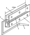
- a test piece having a width of 4 mm, a thickness of 4 mm, and a length of 10 mm is cut out from the sprue portion of FIG. 1 obtained when the composite is molded.
- a load of 2 g was applied to the cut specimen, and a linear expansion coefficient in a temperature range of 50 to 150 ° C. was measured at a heating rate of 5 ° C./min. The average value was taken as the linear expansion coefficient of the thermoplastic resin.
- Example 1 The aluminum test piece surface-treated in treatment 1 is preheated with a natural convection dryer SONW-450 set at 200 ° C and attached to the injection molding machine SE-100D of Sumitomo Heavy Industries, Ltd. 1 was placed in a mold capable of molding the composite of FIG. 1, and a polyamide resin composition in which 12.5% by mass of (a-1) and 87.5% by mass of (a-6) were mixed was injected at the same time. It was introduced into a molding machine, injected into a mold having a mold temperature of 150 ° C. at a resin temperature of 260 ° C., and a holding pressure of 40 MPa was applied for 40 seconds, followed by cooling in the mold for 45 seconds to obtain a composite having the shape shown in FIG. Obtained. The obtained composite was subjected to strength measurement and bondability evaluation. Moreover, the linear expansion coefficient was measured from the cut specimen. The results are shown in Table 1.
- Example 2 A composite was obtained in the same manner as in Example 1 except that (a-1) was changed to 25% by mass and (a-6) was changed to 75% by mass in Example 1. The obtained composite was subjected to strength measurement and bondability evaluation. Moreover, the linear expansion coefficient was measured from the cut specimen. The results are shown in Table 1.
- Example 3 A composite was obtained in the same manner as in Example 1 except that (a-1) was changed to 50% by mass and (a-6) was changed to 50% by mass. The obtained composite was subjected to strength measurement and bondability evaluation. Further, the linear expansion coefficient and the crystallization temperature were measured from the cut specimen. The results are shown in Table 1.
- Example 4 A composite was obtained in the same manner as in Example 1 except that (a-6) was not used and (a-1) was changed to 100% by mass. The obtained composite was subjected to strength measurement and bondability evaluation. Further, the linear expansion coefficient and the crystallization temperature were measured from the cut specimen. The results are shown in Table 1.
- Comparative Example 1 A composite was obtained in the same manner as in Example 1, except that (a-1) was not used and (a-6) was changed to 100% by mass. The obtained composite was subjected to strength measurement and bondability evaluation. Further, the linear expansion coefficient and the crystallization temperature were measured from the cut specimen. The results are shown in Table 1.
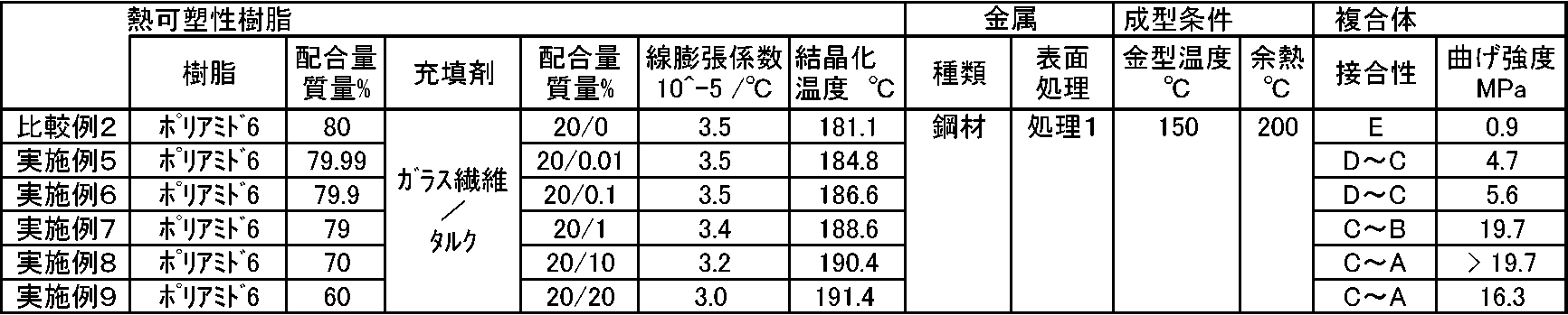
- Example 5 Pre-heated the steel specimen surface treated in treatment 1 with ASW natural convection dryer SONW-450 set at 200 ° C, and attach the specimen to the injection molding machine SE-100D of Sumitomo Heavy Industries, Ltd. 1 is placed in a mold capable of molding the composite of FIG. 1, and (a-2) 2% by mass, (a-7) 66.7% by mass, and (a-11) 31.3% by mass of polyamide
- the resin composition was introduced into the same injection molding machine, injected into a mold having a resin temperature of 270 ° C. and a mold temperature of 150 ° C., a holding pressure of 50 MPa was applied for 45 seconds, and then cooled in the mold for 45 seconds. A composite of shape 1 was obtained. The obtained composite was subjected to strength measurement and bondability evaluation. Further, the linear expansion coefficient and the crystallization temperature were measured from the cut specimen. The results are shown in Table 2.
- Example 6 A composite was prepared in the same manner as in Example 5 except that (a-2) 20% by mass, (a-7) 66.7% by mass, and (a-11) 13.3% by mass were used. Obtained. The obtained composite was subjected to strength measurement and bondability evaluation. Further, the linear expansion coefficient and the crystallization temperature were measured from the cut specimen. The results are shown in Table 2.
- Example 7 In Example 5, a composite was made in the same manner as in Example 5 except that (a-1) 2.5% by mass, (a-7) 66.7% by mass and (a-11) 30.8% by mass were used. Got the body. The obtained composite was subjected to strength measurement and bondability evaluation. Further, the linear expansion coefficient and the crystallization temperature were measured from the cut specimen. The results are shown in Table 2.
- Example 8 A composite was prepared in the same manner as in Example 5 except that (a-1) 25% by mass, (a-7) 66.7% by mass, and (a-11) 8.3% by mass were used. Obtained. The obtained composite was subjected to strength measurement and bondability evaluation. Further, the linear expansion coefficient and the crystallization temperature were measured from the cut specimen. The results are shown in Table 2.
- Example 9 A composite was prepared in the same manner as in Example 5 except that (a-1) 50% by mass, (a-8) 44.4% by mass, and (a-11) 5.6% by mass were used. Obtained. The obtained composite was subjected to strength measurement and bondability evaluation. Further, the linear expansion coefficient and the crystallization temperature were measured from the cut specimen. The results are shown in Table 2.
- Comparative Example 2 A composite was obtained in the same manner as in Example 5 except that (a-7) 66.7% by mass and (a-11) 33.3% by mass were used. The obtained composite was subjected to strength measurement and bondability evaluation. Further, the linear expansion coefficient and the crystallization temperature were measured from the cut specimen. The results are shown in Table 2.
- Example 10 Pre-heated the stainless steel test piece surface-treated in treatment 1 with the natural convection dryer SONW-450 set at 200 ° C and attached to the injection molding machine SE-100D of Sumitomo Heavy Industries, Ltd. 1 is installed in a mold capable of molding the composite shown in FIG. 1, and (a-1) is introduced into the same injection molding machine and injected into a mold having a resin temperature of 270 ° C. and a mold temperature of 140 ° C. After applying 60 MPa for 15 seconds, the composite of the shape of FIG. 1 was obtained by cooling in the mold for 30 seconds. The obtained composite was subjected to strength measurement and bondability evaluation. Further, the linear expansion coefficient and the crystallization temperature were measured from the cut specimen. The results are shown in Table 3.
- Example 11 In Example 10, a composite was obtained in the same manner as in Example 10 except that the stainless steel test piece surface-treated in treatment 1 was changed to a steel test piece surface-treated in treatment 1. The obtained composite was subjected to strength measurement and bondability evaluation. Further, the linear expansion coefficient and the crystallization temperature were measured from the cut specimen. The results are shown in Table 3.
- Example 12 A composite was obtained in the same manner as in Example 10 except that the stainless steel test piece surface-treated in treatment 1 was changed to the aluminum test piece surface-treated in treatment 1. The obtained composite was subjected to strength measurement and bondability evaluation. Further, the linear expansion coefficient and the crystallization temperature were measured from the cut specimen. The results are shown in Table 3.
- Example 13 A composite was obtained in the same manner as in Example 10 except that the stainless steel test piece surface-treated in treatment 1 was changed to a stainless steel test piece surface-treated in treatment 2. The obtained composite was subjected to strength measurement and bondability evaluation. Further, the linear expansion coefficient and the crystallization temperature were measured from the cut specimen. The results are shown in Table 3.
- Example 14 In Example 13, a composite was obtained in the same manner as in Example 10 except that the stainless steel test piece surface-treated in treatment 2 was changed to a steel test piece surface-treated in treatment 2. The obtained composite was subjected to strength measurement and bondability evaluation. Further, the linear expansion coefficient and the crystallization temperature were measured from the cut specimen. The results are shown in Table 3.
- Example 15 A composite was obtained in the same manner as in Example 10 except that the stainless steel test piece surface-treated in the treatment 2 was changed to the aluminum test piece surface-treated in the treatment 2. The obtained composite was subjected to strength measurement and bondability evaluation. Further, the linear expansion coefficient and the crystallization temperature were measured from the cut specimen. The results are shown in Table 3.
- Example 16 Pre-heated the stainless steel test piece surface-treated in treatment 1 with the natural convection dryer SONW-450 set at 200 ° C and attached to the injection molding machine SE-100D of Sumitomo Heavy Industries, Ltd. 1 is installed in a mold capable of molding the composite shown in FIG. 1, and (a-3) is introduced into the same injection molding machine and injected into a mold having a resin temperature of 270 ° C. and a mold temperature of 140 ° C. After applying 60 MPa for 15 seconds, it was cooled in a mold for 30 seconds to obtain a composite having the shape of FIG. The obtained composite was subjected to strength measurement and bondability evaluation. Further, the linear expansion coefficient and the crystallization temperature were measured from the cut specimen. The results are shown in Table 3.
- Example 17 In Example 16, a composite was obtained in the same manner as in Example 16 except that the stainless steel test piece surface-treated in treatment 1 was changed to a steel test piece surface-treated in treatment 1. The obtained composite was subjected to strength measurement and bondability evaluation. Further, the linear expansion coefficient and the crystallization temperature were measured from the cut specimen. The results are shown in Table 3.
- Example 18 A composite was obtained in the same manner as in Example 16 except that the stainless steel test piece surface-treated in the treatment 1 was changed to the aluminum test piece surface-treated in the treatment 1. The obtained composite was subjected to strength measurement and bondability evaluation. Further, the linear expansion coefficient and the crystallization temperature were measured from the cut specimen. The results are shown in Table 3.
- Example 19 A composite was obtained in the same manner as in Example 16 except that the stainless steel test piece surface-treated in the treatment 1 was changed to the stainless steel test piece surface-treated in the treatment 2. The obtained composite was subjected to strength measurement and bondability evaluation. Further, the linear expansion coefficient and the crystallization temperature were measured from the cut specimen. The results are shown in Table 3.
- Example 20 In Example 19, a composite was obtained in the same manner as in Example 19 except that the stainless steel test piece surface-treated in treatment 2 was changed to a steel test piece surface-treated in treatment 2. The obtained composite was subjected to strength measurement and bondability evaluation. Further, the linear expansion coefficient and the crystallization temperature were measured from the cut specimen. The results are shown in Table 3.
- Example 21 A composite was obtained in the same manner as in Example 19 except that the stainless steel test piece surface-treated in the treatment 2 was changed to the aluminum test piece surface-treated in the treatment 2. The obtained composite was subjected to strength measurement and bondability evaluation. Further, the linear expansion coefficient and the crystallization temperature were measured from the cut specimen. The results are shown in Table 3.
- Example 22 A composite was obtained in the same manner as in Example 10 except that the resin composition was a mixture of (a-1) 50% by mass and (a-9) 50% by mass and the mold temperature was 120 ° C. . The obtained composite was subjected to strength measurement and bondability evaluation. Moreover, the linear expansion coefficient was measured from the cut specimen. The results are shown in Table 3.
- Example 23 A composite was obtained in the same manner as in Example 22 except that the resin composition was (a-4) and the metal type was aluminum in Example 22, and the bondability was evaluated. Further, the linear expansion coefficient and the crystallization temperature were measured from the cut specimen. The results are shown in Table 3.
- Example 24 A composite was obtained in the same manner as in Example 23 except that the resin composition graphite was changed from magnesium oxide to resin composition (a-5) in Example 23, and the bondability was evaluated. Further, the linear expansion coefficient and the crystallization temperature were measured from the cut specimen. The results are shown in Table 3.
- Comparative Example 3 Pre-heated the stainless steel test piece surface-treated in treatment 1 with the natural convection dryer SONW-450 set at 180 ° C and attached the test piece to the injection molding machine SE-100D of Sumitomo Heavy Industries, Ltd. 1 is installed in a mold capable of molding the composite shown in FIG. 1, and (a-7) is introduced into the same injection molding machine and injected into a mold having a resin temperature of 290 ° C. and a mold temperature of 80 ° C. After applying 60 MPa for 15 seconds, it was cooled in a mold for 30 seconds to obtain a composite having the shape of FIG. The obtained composite was subjected to strength measurement and bondability evaluation. Further, the linear expansion coefficient and the crystallization temperature were measured from the cut specimen. The results are shown in Table 3.
- Comparative Example 4 In Comparative Example 3, a composite was obtained in the same manner as in Comparative Example 3, except that the stainless steel test piece surface-treated in Treatment 1 was changed to a steel test piece surface-treated in Treatment 1. The obtained composite was subjected to strength measurement and bondability evaluation. Further, the linear expansion coefficient and the crystallization temperature were measured from the cut specimen. The results are shown in Table 3.
- Comparative Example 5 In Comparative Example 3, a composite was obtained in the same manner as in Comparative Example 3, except that the stainless steel test piece surface-treated in Treatment 1 was replaced with the aluminum test piece surface-treated in Treatment 1. The obtained composite was subjected to strength measurement and bondability evaluation. Further, the linear expansion coefficient and the crystallization temperature were measured from the cut specimen. The results are shown in Table 3.
- Comparative Example 6 In Comparative Example 3, a composite was obtained in the same manner as in Comparative Example 3, except that the stainless steel test piece surface-treated in the treatment 1 was changed to a stainless steel test piece surface-treated in the treatment 2. The obtained composite was subjected to strength measurement and bondability evaluation. Further, the linear expansion coefficient and the crystallization temperature were measured from the cut specimen. The results are shown in Table 3.
- Comparative Example 7 In Comparative Example 6, a composite was obtained in the same manner as in Comparative Example 6 except that the stainless steel test piece surface-treated in the treatment 2 was changed to a steel test piece surface-treated in the treatment 2. The obtained composite was subjected to strength measurement and bondability evaluation. Further, the linear expansion coefficient and the crystallization temperature were measured from the cut specimen. The results are shown in Table 3.
- Comparative Example 8 In Comparative Example 6, a composite was obtained in the same manner as in Comparative Example 6 except that the stainless steel test piece surface-treated in the treatment 2 was changed to the aluminum test piece surface-treated in the treatment 2. The obtained composite was subjected to strength measurement and bondability evaluation. Further, the linear expansion coefficient and the crystallization temperature were measured from the cut specimen. The results are shown in Table 3.
- Comparative Example 9 In Comparative Example 3, a composite was obtained in the same manner as in Comparative Example 3, except that the test piece was preheated at 200 ° C and the mold temperature was 150 ° C. The obtained composite was subjected to strength measurement and bondability evaluation. Further, the linear expansion coefficient and the crystallization temperature were measured from the cut specimen. The results are shown in Table 3.
- Comparative Example 10 In Comparative Example 9, a composite was obtained in the same manner as in Comparative Example 9, except that the stainless steel test piece surface-treated in the treatment 1 was changed to a stainless steel test piece surface-treated in the treatment 2. The obtained composite was subjected to strength measurement and bondability evaluation. Further, the linear expansion coefficient and the crystallization temperature were measured from the cut specimen. The results are shown in Table 3.
- Comparative Example 11 A composite was obtained in the same manner as in Comparative Example 9 except that (a-7) was changed to (a-9) in Comparative Example 9. The obtained composite was subjected to strength measurement and bondability evaluation. Further, the linear expansion coefficient and the crystallization temperature were measured from the cut specimen. The results are shown in Table 3.
- Comparative Example 12 In Comparative Example 11, a composite was obtained in the same manner as in Comparative Example 11 except that the stainless steel test piece surface-treated in the treatment 1 was changed to a steel test piece surface-treated in the treatment 1. The obtained composite was subjected to strength measurement and bondability evaluation. Further, the linear expansion coefficient and the crystallization temperature were measured from the cut specimen. The results are shown in Table 3.
- Comparative Example 13 In Comparative Example 11, a composite was obtained in the same manner as in Comparative Example 11 except that the stainless steel test piece surface-treated in Treatment 1 was replaced with the aluminum test piece surface-treated in Treatment 1. The obtained composite was subjected to strength measurement and bondability evaluation. Further, the linear expansion coefficient and the crystallization temperature were measured from the cut specimen. The results are shown in Table 3.
- Comparative Example 14 A composite was obtained in the same manner as in Comparative Example 9 except that (a-9) was changed to (a-6) in Comparative Example 9. The obtained composite was subjected to strength measurement and bondability evaluation. Further, the linear expansion coefficient and the crystallization temperature were measured from the cut specimen. The results are shown in Table 3.
- Comparative Example 15 In Comparative Example 14, a composite was obtained in the same manner as in Comparative Example 11 except that the stainless steel test piece surface-treated in the treatment 1 was changed to a stainless steel test piece surface-treated in the treatment 2. The obtained composite was subjected to strength measurement and bondability evaluation. Further, the linear expansion coefficient and the crystallization temperature were measured from the cut specimen. The results are shown in Table 3.
- Comparative Example 16 Pre-heated the stainless steel test piece surface-treated in treatment 1 with the natural convection dryer SONW-450 set at 200 ° C and attached to the injection molding machine SE-100D of Sumitomo Heavy Industries, Ltd. 1 is installed in a mold capable of molding the composite shown in FIG. 1 and (a-10) is introduced into the same injection molding machine and injected into a mold having a resin temperature of 290 ° C. and a mold temperature of 80 ° C. After applying 60 MPa for 15 seconds, the composite of the shape of FIG. 1 was obtained by cooling in the mold for 30 seconds. The obtained composite was subjected to strength measurement and bondability evaluation. The results are shown in Table 3.
- Comparative Example 17 In Comparative Example 16, a composite was obtained in the same manner as in Comparative Example 16 except that the stainless steel test piece surface-treated in the treatment 1 was changed to a stainless steel test piece surface-treated in the treatment 2. The obtained composite was subjected to strength measurement and bondability evaluation. The results are shown in Table 3.
- Comparative Example 18 A composite was obtained in the same manner as in Comparative Example 16 except that (a-10) was changed to (a-8) in Comparative Example 16. The obtained composite was subjected to strength measurement and bondability evaluation. Further, the linear expansion coefficient and the crystallization temperature were measured from the cut specimen. The results are shown in Table 3.
- Comparative Example 19 In Comparative Example 18, a composite was obtained in the same manner as Comparative Example 18 except that the stainless steel test piece surface-treated in Treatment 1 was changed to a steel test piece surface-treated in Treatment 1. The obtained composite was subjected to strength measurement and bondability evaluation. Further, the linear expansion coefficient and the crystallization temperature were measured from the cut specimen. The results are shown in Table 3.
- Comparative Example 20 A composite was obtained in the same manner as in Comparative Example 18 except that the stainless steel test piece surface-treated in Treatment 1 was replaced with the aluminum test piece surface-treated in Treatment 1. The obtained composite was subjected to strength measurement and bondability evaluation. Further, the linear expansion coefficient and the crystallization temperature were measured from the cut specimen. The results are shown in Table 3.
Landscapes
- Engineering & Computer Science (AREA)
- Mechanical Engineering (AREA)
- Manufacturing & Machinery (AREA)
- Laminated Bodies (AREA)
- Injection Moulding Of Plastics Or The Like (AREA)
- Compositions Of Macromolecular Compounds (AREA)
Abstract
Description
即ち、本発明は、熱可塑性樹脂組成物(A)と金属(B)とが接触接合した複合体であって、
前記熱可塑性樹脂組成物(A)は、熱可塑性樹脂と該熱可塑性樹脂の結晶化温度を3℃以上上昇させる無機充填材とを含む組成物であり、
前記金属(B)は、表面処理した金属である複合体を提供するものである。
本発明においては、前記熱可塑性樹脂は、ポリアミド樹脂であることが好ましい。
また、前記無機充填材は、タルク、グラファイト、酸化マグネシウム、カオリン及び炭酸カルシウムからなる群より選ばれる少なくとも一種であることが好ましい。
また、前記無機充填材は、タルク、グラファイト及び酸化マグネシウムからなる群より選ばれる少なくとも一種であることが好ましい。
また、前記無機充填材の配合量は、前記熱可塑性樹脂組成物(A)中に、0.01質量%以上50質量%以下であることが好ましい。
また、前記金属(B)の表面処理は、その表面に微細な凹凸を形成する処理又は化学物質を固着させる処理であることが好ましい。
また、本発明の複合体は、前記熱可塑性樹脂組成物(A)と前記金属(B)とが射出成形により接触接合されたものであることが好ましい。
更に、前記熱可塑性樹脂組成物(A)の、前記熱可塑性樹脂組成物(A)と前記金属(B)との接合面に対して対向する面には、リブ、突起、穴、段差から選ばれた1種からなる収縮抑制構造が設けられていてもよい。
更に、本発明の複合体は、全体形状が管または棒状であり、樹脂と金属が多層構成をなしているものでもよい。
また本発明の複合体は、金属表面の微細凹凸に樹脂を流入、固化させる技術と金属表面に化合物を固着させて樹脂と接合させる技術の両方に有効である。したがって、従来できなかった化合物が金属表面に固着した金属に熱可塑性樹脂を射出成形により接合させることが、本発明により可能になり、熱可塑性樹脂と化合物が金属表面に固着した金属とが接触接合した複合体が製造することができる。
本発明で用いる熱可塑性樹脂組成物(A)は、熱可塑性樹脂と、該熱可塑性樹脂の結晶化温度を3℃以上上昇させる無機充填材とを含む組成物である。
(1)熱可塑性樹脂
熱可塑性樹脂組成物(A)に使用される熱可塑性樹脂は、特に限定されるものではないが、高密度ポリエチレン(HDPE)、中密度ポリエチレン(MDPE)、低密度ポリエチレン(LDPE)、直鎖状低密度ポリエチレン(LLDPE)、超高分子量ポリエチレン(UHMWPE)、ポリプロピレン(PP)、エチレン/プロピレン共重合体(EPR)、エチレン/ブテン共重合体(EBR)、エチレン/酢酸ビニル共重合体(EVA)、エチレン/アクリル酸共重合体(EAA)、エチレン/メタクリル酸共重合体(EMAA)、エチレン/アクリル酸メチル共重合体(EMA)、エチレン/メタクリル酸メチル共重合体(EMMA)、エチレン/アクリル酸エチル共重合体(EEA)等のポリオレフィン系樹脂及び、アクリル酸、メタクリル酸、マレイン酸、フマル酸、イタコン酸、クロトン酸、メサコン酸、シトラコン酸、グルタコン酸、シス-4-シクロヘキセン-1,2-ジカルボン酸、エンドビシクロ-[2.2.1]-5-ヘプテン-2,3-ジカルボン酸等のカルボキシル基及びその金属塩(Na、Zn、K、Ca、Mg)、無水マレイン酸、無水イタコン酸、無水シトラコン酸、エンドビシクロ-[2.2.1]-5-ヘプテン-2,3-ジカルボン酸無水物等の酸無水物基、アクリル酸グリシジル、メタクリル酸グリシジル、エタクリル酸グリシジル、イタコン酸グリシジル、シトラコン酸グリシジル等のエポキシ基等の官能基が含有された化合物により変性された、上記ポリオレフィン系樹脂、ポリブチレンテレフタレート(PBT)、ポリエチレンテレフタレート(PET)、ポリトリメチレンテレフタレート(PTT)、ポリエチレンイソフタレート(PEI)、PET/PEI共重合体、ポリアリレート(PAR)、ポリブチレンナフタレート(PBN)、ポリエチレンナフタレート(PEN)、液晶ポリエステル(LCP)、ポリ乳酸(PLA)、ポリグリコール酸(PGA)等のポリエステル系樹脂、ポリアセタール(POM)、ポリフェニレンオキシド(PPO)等のポリエーテル系樹脂、ポリスルホン(PSF)、ポリエーテルスルホン(PES)等のポリスルホン系樹脂、ポリフェニレンサルファイド樹脂(PPS)、ポリチオエーテルスルホン樹脂(PTES)等のポリチオエーテル系樹脂、ポリエーテルエーテルケトン(PEEK)、ポリアリルエーテルケトン(PAEK)等のポリケトン系樹脂、ポリアクリロニトリル(PAN)、ポリメタクリロニトリル、アクリロニトリル/スチレン共重合体(AS)、メタクリロニトリル/スチレン共重合体、アクリロニトリル/ブタジエン/スチレン共重合体(ABS)、メタクリロニトリル/スチレン/ブタジエン共重合体(MBS)等のポリニトリル系樹脂、ポリメタクリル酸メチル(PMMA)、ポリメタクリル酸エチル(PEMA)等のポリメタクリレート系樹脂、ポリ酢酸ビニル(PVAc)等のポリビニルエステル系樹脂、ポリ塩化ビニリデン(PVDC)、ポリ塩化ビニル(PVC)、塩化ビニル/塩化ビニリデン共重合体、塩化ビニリデン/メチルアクリレート共重合体等のポリビニル系樹脂、酢酸セルロース、酪酸セルロース等のセルロース系樹脂、ポリカーボネート(PC)等のポリカーボネート系樹脂、熱可塑性ポリイミド(PI)、ポリアミドイミド(PAI)、ポリエーテルイミド等のポリイミド系樹脂、ポリフッ化ビニリデン(PVDF)、ポリフッ化ビニル(PVF)、エチレン/テトラフルオロエチレン共重合体(ETFE)、ポリクロロトリフルオロエチレン(PCTFE)、エチレン/クロロトリフルオロエチレン共重合体(ECTFE)、テトラフルオロエチレン/ヘキサフルオロプロピレン共重合体(TFE/HFP,FEP)、テトラフルオロエチレン/ヘキサフルオロプロピレン/フッ化ビニリデン共重合体(TFE/HFP/VDF,THV)、テトラフルオロエチレン/パーフルオロ(アルキルビニルエーテル)共重合体(PFA)等のフッ素系樹脂、熱可塑性ポリウレタン系樹脂、ポリウレタンエラストマー、本発明において規定した以外のポリアミドエラストマー、ポリエステルエラストマー等が挙げられる。これらの中でも表面処理した金属との接合力の弱い、ポリブチレンテレフタレート(PBT)、ポリフェニレンサルファイド樹脂(PPS)以外の、比較的明瞭な結晶化または凝固温度を示す熱可塑性樹脂が、金属との接合効果改善の観点から好ましく、成形性等の取り扱いの容易さや高い耐熱性、機械強度からポリアミド樹脂がより好ましい。これらは1種又は2種以上を用いることができる。
熱可塑性樹脂組成物(A)に用いられる該熱可塑性樹脂の結晶化温度を3℃以上上昇させる無機充填材としては、該熱可塑性樹脂の結晶化温度を3℃以上上昇させる無機充填材であればよく、複合体の接合強度の観点から、該熱可塑性樹脂の結晶化温度を6℃以上上昇させる無機充填材が好ましい。
具体的な熱可塑性樹脂の結晶化温度を3℃以上上昇させる無機充填材としては、タルク、グラファイト、酸化マグネシウム、カオリン及び炭酸カルシウムからなる群より選ばれる少なくとも1種が好ましく、タルク、グラファイト及び酸化マグネシウムからなる群より選ばれる少なくとも一種がより好ましい。
本発明の金属(B)は、表面処理した金属であれば、金属の材質として特に限定するものではなく、例えば、鉄,銅,ニッケル,金,銀,プラチナ,コバルト,亜鉛,鉛,スズ,チタン,クロム,アルミニウム,マグネシウム,マンガン及びこれらの合金(ステンレス,真鍮,リン青銅など)を挙げることができる。また薄膜の金属や被膜(金属メッキ,蒸着膜,塗膜等)がなされた金属も対象となる。

(上式において、Rは-OR1,-OOR1,-SmR1,-NR1(R2);R1,R2はH,水酸基,カルボニル基,エーテル基,エステル基,アミド基,アミノ基,フェニル基,シクロアルキル基,アルキル基,あるいは、アルキン,アルケンの様な不飽和基を含む置換基であり、m は1から8までの整数を意味し、MはH,もしくは、Na,Li,K,Ba,Ca,アンモニウム塩などのアルカリ)が好ましい。
本発明において、熱可塑性樹脂組成物(A)と金属(B)とを接触接合する方法については、特に制限されるものではないが、射出成形により接触接合することが好ましい。例えば、金型の一方に金属(B)を設置し、金型を閉め、熱可塑性樹脂組成物(A)を射出成形機のホッパー部から射出成形機に導入し、溶融した樹脂を金型内に射出し、可動金型を開き離型することにより、熱可塑性樹脂組成物(A)と金属(B)とを接合した複合体を得ることができる。
射出成形の条件は、熱可塑性樹脂の種類により異なり、特に制限はないが、金型温度は10℃以上160℃以下が好ましい。一般には強度など製品品質と成形サイクルの観点から40℃以上120℃以下がより好ましいが、金属と接合させる射出成形については90℃以上がさらに好ましい。
・ポリアミド樹脂組成物(a-1)
1質量%のアミノシランカップリング剤で表面処理した平均粒径14μmのタルク(富士タルク工業株式会社のPKP-80)を40質量%と、相対粘度2.47、水抽出分5質量%以下のポリアミド6を60質量%、とからなるポリアミド樹脂組成物。(以下、(a-1)と称する。)
・ポリアミド樹脂組成物(a-2)
(a-1)において、タルクの配合量を0.5質量%とした以外は(a-1)と同様であるポリアミド樹脂組成物(a-2)(以下、(a-2)と称する。)
・ポリアミド樹脂組成物(a-3)
平均粒径が8μmのタルク(日本タルク株式会社のシムゴンM)を30質量%と、相対粘度2.47、水抽出分5質量%以下のポリアミド6を70質量%、とからなるポリアミド樹脂組成物(a-3)(以下、(a-3)と称する。)
・ポリアミド樹脂組成物(a-4)
平均粒径が33μm、かさ密度0.18g/cm3のグラファイト(日本黒鉛工業株式会社のSP-10)を40体積%と、相対粘度2.47、水抽出分5質量%以下のポリアミド6を60体積%、とからなるポリアミド樹脂組成物(a-4)(以下、(a-4)と称する。)
・ポリアミド樹脂組成物(a-5)
平均粒径が2.3μm、かさ密度0.4g/cm3の酸化マグネシウム(宇部マテリアルズ株式会社のRF-50-AC)を40体積%と、相対粘度2.47、水抽出分5質量%以下のポリアミド6を60体積%、とからなるポリアミド樹脂組成物(a-5)(以下、(a-5)と称する。)
・ポリアミド樹脂組成物(a-6)
平均粒径が7~9μmのウォラストナイト(キンセイマテック株式会社のFPW-400S)を40質量%と、相対粘度2.47、水抽出分5質量%以下のポリアミド6を60質量%、とからなるポリアミド樹脂組成物(a-6)(以下、(a-6)と称する。)
・ポリアミド樹脂組成物(a-7)
ガラス繊維(日本電気硝子株式会社のECS03T249)を30質量%と、相対粘度2.64、水抽出分5質量%以下のポリアミド6を70質量%、とからなるポリアミド樹脂組成物(a-7)(以下、(a-7)と称する。)
・ポリアミド樹脂組成物(a-8)
ガラス繊維(日本電気硝子株式会社のECS03T249)を45質量%と、相対粘度2.64、水抽出分5質量%以下のポリアミド6を55質量%、とからなるポリアミド樹脂組成物(a-8)(以下、(a-8)と称する。)
・ポリアミド樹脂組成物(a-9)
ガラス繊維(日本電気硝子株式会社のECS03T289)を45質量%と、相対粘度2.75、水抽出分5質量%以下のポリアミド66を55質量%、とからなるポリアミド樹脂組成物(a-9)(以下、(a-9)と称する。)
・ポリアミド樹脂組成物(a-10)
ガラス繊維(日本電気硝子株式会社のECS03T289)を35質量%と、ポリアミド12を5質量%と、芳香族ポリアミドを13質量%と、相対粘度2.75、水抽出分5質量%以下のポリアミド66を47質量%、とからなるポリアミド樹脂組成物(a-10)(以下、(a-10)と称する。)
・ポリアミド6樹脂(a-11)
相対粘度2.47、水抽出分5質量%以下、結晶化温度Tcが179.8℃のポリアミド6樹脂(a-11)(以下、(a-11)と称する。)
外寸が12mm×12mm、厚みが1.0mm、長さが150mmであるステンレス、鋼材及びアルミニウムの試験片を準備する。
ステンレスは、18%のCrと8%のNiを含むステンレス鋼であるSUS304-HLを使用し、
鋼材は、機械構造用角形鋼管の規格のSTKMR290を使用し、
アルミニウムは、JIS H4040:2006に規定されるA5052を使用した。
それぞれの試験片の表面に対して、微細凹凸を形成するものとして特許文献1に記載されている侵食性液体(ヒドラジン)を用いた表面処理(以下処理1ともいう。)、もしくは、金属表面に固着するものとして特許文献3に記載されているトリアジンジチオール誘導体を用いる表面処理(以下処理2ともいう。)を施した。
表面処理後の金属はポリエチレンとアルミニウムの多層袋の中に入れ、ヒートシール機で密封し、樹脂との接合成形の直前まで室温で保管した。
図1の1に示す複合体の金属部材をERON社製万力N735に固定する。樹脂部の開口側に200mm×150mm×12mmのSUS304製板材を挿入し、曲げ荷重を挿入した板材の複合体の樹脂と金属の境界面である図1の斜線部分4から0.2m離れた部分にかけて複合体を破壊させた。破壊時の曲げモーメントを接合面全体の断面係数で割り、曲げ強度を求めた。具体的には、下記式より求めた。
曲げ強度(Pa)=0.2(m)×破壊時の荷重(N)/(0.15(m)×0.012(m)×0.012(m)/6)
接合性とは、その破壊面の状態を下記のA~Eの5段階で評価したものである。
A:剥離させるのに工具を要し、金属と樹脂の境界面で剥離せず樹脂部が破壊する。
B:剥離させるのに工具を要し、金属側に0.2mm以上の厚さを持った樹脂が残る。
C:取り出し後、手で剥がれるが、抵抗感があり、金属の剥離面に変色がある。
D:取り出し後手で剥がれ、肉眼では界面に変化がない。
E:突き出し時、または取り出し時に手を触れることなく剥離する。
複合体を成形する際に得られる図1の5のスプルー部分から、幅4mm、厚み4mm、長さ10mmの試験片を切り出す。セイコーインスツル株式会社のTMA装置SSC5000を用い、切り出した試験片に2gの荷重をかけ、5℃/分の昇温速度にて50~150℃の温度範囲の線膨張係数を測定し、その間の平均値を熱可塑性樹脂の線膨張係数とした。
線膨張係数と同様、スプルー部分から直径6mm、厚さ1mmの円板寸法からはみ出さない薄板状試験片を切り出す。装置はセイコーインスツル株式会社製示差走査熱量計EXSTAR6000 DSC6220を用いて窒素雰囲気中で測定した。試験片は室温から250℃まで10℃/分の速度で昇温し、250℃で10分保持した後、25℃まで10℃/分の速度で降温した。得られたDSCチャートで降温のピーク温度をTcとした。
処理1で表面処理したアルミニウムの試験片を200℃に設定したアズワン株式会社の自然対流乾燥器SONW-450で予熱し、その試験片を住友重機械工業株式会社の射出成形機SE-100Dに取り付けた図1の複合体が成形できる金型内に設置し、(a-1)を12.5質量%と(a-6)を87.5質量%とを混合したポリアミド樹脂組成物を同射出成形機に導入し、金型温度150℃の金型に樹脂温度260℃で射出し、保持圧力40MPaを40秒間かけた後、金型内で45秒冷却し、図1の形状の複合体を得た。得られた複合体の強度測定および接合性評価を行った。また、切り出した試験片から線膨張係数の測定を行った。その結果を表1に示す。
実施例1において、(a-1)を25質量%、(a-6)を75質量%にした以外は、実施例1と同様にして複合体を得た。得られた複合体の強度測定および接合性評価を行った。また、切り出した試験片から線膨張係数の測定を行った。その結果を表1に示す。
実施例1において、(a-1)を50質量%、(a-6)を50質量%にした以外は、実施例1と同様にして複合体を得た。得られた複合体の強度測定および接合性評価を行った。また、切り出した試験片から線膨張係数と結晶化温度の測定を行った。その結果を表1に示す。
実施例1において、(a-6)を使用せず、(a-1)を100質量%にした以外は、実施例1と同様にして複合体を得た。得られた複合体の強度測定および接合性評価を行った。また、切り出した試験片から線膨張係数と結晶化温度の測定を行った。その結果を表1に示す。
実施例1において、(a-1)を使用せず、(a-6)を100質量%にした以外は、実施例1と同様にして複合体を得た。得られた複合体の強度測定および接合性評価を行った。また、切り出した試験片から線膨張係数と結晶化温度の測定を行った。その結果を表1に示す。

処理1で表面処理した鋼材の試験片を200℃に設定したアズワン株式会社の自然対流乾燥器SONW-450で予熱し、その試験片を住友重機械工業株式会社の射出成形機SE-100Dに取り付けた図1の複合体が成形できる金型内に設置し、(a-2)2質量%、(a-7)66.7質量%及び(a-11)31.3質量%を混合したポリアミド樹脂組成物を同射出成形機に導入し、樹脂温度270℃で、金型温度150℃の金型に射出し、保持圧力50MPaを45秒間にかけた後、金型内で45秒冷却し、図1の形状の複合体を得た。得られた複合体の強度測定および接合性評価を行った。また、切り出した試験片から線膨張係数と結晶化温度の測定を行った。その結果を表2に示す。
実施例5において、(a-2)20質量%、(a-7)66.7質量%及び(a-11)13.3質量%にした以外は、実施例5と同様にして複合体を得た。得られた複合体の強度測定および接合性評価を行った。また、切り出した試験片から線膨張係数と結晶化温度の測定を行った。その結果を表2に示す。
実施例5において、(a-1)2.5質量%、(a-7)66.7質量%及び(a-11)30.8質量%にした以外は、実施例5と同様にして複合体を得た。得られた複合体の強度測定および接合性評価を行った。また、切り出した試験片から線膨張係数と結晶化温度の測定を行った。その結果を表2に示す。
実施例5において、(a-1)25質量%、(a-7)66.7質量%及び(a-11)8.3質量%にした以外は、実施例5と同様にして複合体を得た。得られた複合体の強度測定および接合性評価を行った。また、切り出した試験片から線膨張係数と結晶化温度の測定を行った。その結果を表2に示す。
実施例5において、(a-1)50質量%、(a-8)44.4質量%及び(a-11)5.6質量%にした以外は、実施例5と同様にして複合体を得た。得られた複合体の強度測定および接合性評価を行った。また、切り出した試験片から線膨張係数と結晶化温度の測定を行った。その結果を表2に示す。
実施例5において、(a-7)66.7質量%及び(a-11)33.3質量%にした以外は、実施例5と同様にして複合体を得た。得られた複合体の強度測定および接合性評価を行った。また、切り出した試験片から線膨張係数と結晶化温度の測定を行った。その結果を表2に示す。
処理1で表面処理したステンレスの試験片を200℃に設定したアズワン株式会社の自然対流乾燥器SONW-450で予熱し、その試験片を住友重機械工業株式会社の射出成形機SE-100Dに取り付けた図1の複合体が成形できる金型内に設置し、(a-1)を同射出成形機に導入し、樹脂温度270℃で、金型温度140℃の金型に射出し、保持圧力60MPaを15秒間かけた後、金型内で30秒冷却することにより図1の形状の複合体を得た。得られた複合体の強度測定および接合性評価を行った。また、切り出した試験片から線膨張係数と結晶化温度の測定を行った。その結果を表3に示す。
実施例10において、処理1で表面処理したステンレスの試験片を処理1で表面処理した鋼材の試験片にした以外は、実施例10と同様にして複合体を得た。得られた複合体の強度測定および接合性評価を行った。また、切り出した試験片から線膨張係数と結晶化温度の測定を行った。その結果を表3に示す。
実施例10において、処理1で表面処理したステンレスの試験片を処理1で表面処理したアルミニウムの試験片にした以外は、実施例10と同様にして複合体を得た。得られた複合体の強度測定および接合性評価を行った。また、切り出した試験片から線膨張係数と結晶化温度の測定を行った。その結果を表3に示す。
実施例10において、処理1で表面処理したステンレスの試験片を処理2で表面処理したステンレスの試験片にした以外は、実施例10と同様にして複合体を得た。得られた複合体の強度測定および接合性評価を行った。また、切り出した試験片から線膨張係数と結晶化温度の測定を行った。その結果を表3に示す。
実施例13において、処理2で表面処理したステンレスの試験片を処理2で表面処理した鋼材の試験片にした以外は、実施例10と同様にして複合体を得た。得られた複合体の強度測定および接合性評価を行った。また、切り出した試験片から線膨張係数と結晶化温度の測定を行った。その結果を表3に示す。
実施例13において、処理2で表面処理したステンレスの試験片を処理2で表面処理したアルミニウムの試験片にした以外は、実施例10と同様にして複合体を得た。得られた複合体の強度測定および接合性評価を行った。また、切り出した試験片から線膨張係数と結晶化温度の測定を行った。その結果を表3に示す。
処理1で表面処理したステンレスの試験片を200℃に設定したアズワン株式会社の自然対流乾燥器SONW-450で予熱し、その試験片を住友重機械工業株式会社の射出成形機SE-100Dに取り付けた図1の複合体が成形できる金型内に設置し、(a-3)を同射出成形機に導入し、樹脂温度270℃で、金型温度140℃の金型に射出し、保持圧力60MPaを15秒間かけた後、金型内で30秒冷却し、図1の形状の複合体を得た。得られた複合体の強度測定および接合性評価を行った。また、切り出した試験片から線膨張係数と結晶化温度の測定を行った。その結果を表3に示す。
実施例16において、処理1で表面処理したステンレスの試験片を処理1で表面処理した鋼材の試験片にした以外は、実施例16と同様にして複合体を得た。得られた複合体の強度測定および接合性評価を行った。また、切り出した試験片から線膨張係数と結晶化温度の測定を行った。その結果を表3に示す。
実施例16において、処理1で表面処理したステンレスの試験片を処理1で表面処理したアルミニウムの試験片にした以外は、実施例16と同様にして複合体を得た。得られた複合体の強度測定および接合性評価を行った。また、切り出した試験片から線膨張係数と結晶化温度の測定を行った。その結果を表3に示す。
実施例16において、処理1で表面処理したステンレスの試験片を処理2で表面処理したステンレスの試験片にした以外は、実施例16と同様にして複合体を得た。得られた複合体の強度測定および接合性評価を行った。また、切り出した試験片から線膨張係数と結晶化温度の測定を行った。その結果を表3に示す。
実施例19において、処理2で表面処理したステンレスの試験片を処理2で表面処理した鋼材の試験片にした以外は、実施例19と同様にして複合体を得た。得られた複合体の強度測定および接合性評価を行った。また、切り出した試験片から線膨張係数と結晶化温度の測定を行った。その結果を表3に示す。
実施例19において、処理2で表面処理したステンレスの試験片を処理2で表面処理したアルミニウムの試験片にした以外は、実施例19と同様にして複合体を得た。得られた複合体の強度測定および接合性評価を行った。また、切り出した試験片から線膨張係数と結晶化温度の測定を行った。その結果を表3に示す。
実施例10において樹脂組成物を(a-1)50質量%および(a-9)50質量%の混合物、金型温度を120℃とした以外は実施例10と同様にして複合体を得た。得られた複合体の強度測定および接合性評価を行った。また、切り出した試験片から線膨張係数の測定を行った。その結果を表3に示す。
実施例22において樹脂組成物を(a-4)、金属の種類をアルミニウムにした以外は実施例22と同様にして複合体を得、接合性の評価を行った。また切り出した試験片から線膨張係数と結晶化温度の測定を行った。その結果を表3に示す。
実施例23において樹脂組成物のグラファイトを酸化マグネシウムにして樹脂組成物(a-5)とした以外は実施例23と同様にして複合体を得、接合性の評価を行った。また切り出した試験片から線膨張係数と結晶化温度の測定を行った。その結果を表3に示す。
処理1で表面処理したステンレスの試験片を180℃に設定したアズワン株式会社の自然対流乾燥器SONW-450で予熱し、その試験片を住友重機械工業株式会社の射出成形機SE-100Dに取り付けた図1の複合体が成形できる金型内に設置し、(a-7)を同射出成形機に導入し、樹脂温度290℃で、金型温度80℃の金型に射出し、保持圧力60MPaを15秒間かけた後、金型内で30秒冷却し、図1の形状の複合体を得た。得られた複合体の強度測定および接合性評価を行った。また、切り出した試験片から線膨張係数と結晶化温度の測定を行った。その結果を表3に示す。
比較例3において、処理1で表面処理したステンレスの試験片を処理1で表面処理した鋼材の試験片にした以外は、比較例3と同様にして複合体を得た。得られた複合体の強度測定および接合性評価を行った。また、切り出した試験片から線膨張係数と結晶化温度の測定を行った。その結果を表3に示す。
比較例3において、処理1で表面処理したステンレスの試験片を処理1で表面処理したアルミニウムの試験片にした以外は、比較例3と同様にして複合体を得た。得られた複合体の強度測定および接合性評価を行った。また、切り出した試験片から線膨張係数と結晶化温度の測定を行った。その結果を表3に示す。
比較例3において、処理1で表面処理したステンレスの試験片を処理2で表面処理したステンレスの試験片にした以外は、比較例3と同様にして複合体を得た。得られた複合体の強度測定および接合性評価を行った。また、切り出した試験片から線膨張係数と結晶化温度の測定を行った。その結果を表3に示す。
比較例6において、処理2で表面処理したステンレスの試験片を処理2で表面処理した鋼材の試験片にした以外は、比較例6と同様にして複合体を得た。得られた複合体の強度測定および接合性評価を行った。また、切り出した試験片から線膨張係数と結晶化温度の測定を行った。その結果を表3に示す。
比較例6において、処理2で表面処理したステンレスの試験片を処理2で表面処理したアルミニウムの試験片にした以外は、比較例6と同様にして複合体を得た。得られた複合体の強度測定および接合性評価を行った。また、切り出した試験片から線膨張係数と結晶化温度の測定を行った。その結果を表3に示す。
比較例3において、試験片を200℃で予熱し、金型温度を150℃にした以外は、比較例3と同様にして複合体を得た。得られた複合体の強度測定および接合性評価を行った。また、切り出した試験片から線膨張係数と結晶化温度の測定を行った。その結果を表3に示す。
比較例9において、処理1で表面処理したステンレスの試験片を処理2で表面処理したステンレスの試験片にした以外は、比較例9と同様にして複合体を得た。得られた複合体の強度測定および接合性評価を行った。また、切り出した試験片から線膨張係数と結晶化温度の測定を行った。その結果を表3に示す。
比較例9において、(a-7)を(a-9)にした以外は、比較例9と同様にして複合体を得た。得られた複合体の強度測定および接合性評価を行った。また、切り出した試験片から線膨張係数と結晶化温度の測定を行った。その結果を表3に示す。
比較例11において、処理1で表面処理したステンレスの試験片を処理1で表面処理した鋼材の試験片にした以外は、比較例11と同様にして複合体を得た。得られた複合体の強度測定および接合性評価を行った。また、切り出した試験片から線膨張係数と結晶化温度の測定を行った。その結果を表3に示す。
比較例11において、処理1で表面処理したステンレスの試験片を処理1で表面処理したアルミニウムの試験片にした以外は、比較例11と同様にして複合体を得た。得られた複合体の強度測定および接合性評価を行った。また、切り出した試験片から線膨張係数と結晶化温度の測定を行った。その結果を表3に示す。
比較例9において、(a-9)を(a-6)にした以外は、比較例9と同様にして複合体を得た。得られた複合体の強度測定および接合性評価を行った。また、切り出した試験片から線膨張係数と結晶化温度の測定を行った。その結果を表3に示す。
比較例14において、処理1で表面処理したステンレスの試験片を処理2で表面処理したステンレスの試験片にした以外は、比較例11と同様にして複合体を得た。得られた複合体の強度測定および接合性評価を行った。また、切り出した試験片から線膨張係数と結晶化温度の測定を行った。その結果を表3に示す。
処理1で表面処理したステンレスの試験片を200℃に設定したアズワン株式会社の自然対流乾燥器SONW-450で予熱し、その試験片を住友重機械工業株式会社の射出成形機SE-100Dに取り付けた図1の複合体が成形できる金型内に設置し、(a-10)を同射出成形機に導入し、樹脂温度290℃で、金型温度80℃の金型に射出し、保持圧力60MPaを15秒間かけた後、金型内で30秒冷却することにより図1の形状の複合体を得た。得られた複合体の強度測定および接合性評価を行った。その結果を表3に示す。
比較例16において、処理1で表面処理したステンレスの試験片を処理2で表面処理したステンレスの試験片にした以外は、比較例16と同様にして複合体を得た。得られた複合体の強度測定および接合性評価を行った。その結果を表3に示す。
比較例16において、(a-10)を(a-8)にした以外は、比較例16と同様にして複合体を得た。得られた複合体の強度測定および接合性評価を行った。また、切り出した試験片から線膨張係数と結晶化温度の測定を行った。その結果を表3に示す。
比較例18において、処理1で表面処理したステンレスの試験片を処理1で表面処理した鋼材の試験片にした以外は、比較例18と同様にして複合体を得た。得られた複合体の強度測定および接合性評価を行った。また、切り出した試験片から線膨張係数と結晶化温度の測定を行った。その結果を表3に示す。
比較例18において、処理1で表面処理したステンレスの試験片を処理1で表面処理したアルミニウムの試験片にした以外は、比較例18と同様にして複合体を得た。得られた複合体の強度測定および接合性評価を行った。また、切り出した試験片から線膨張係数と結晶化温度の測定を行った。その結果を表3に示す。
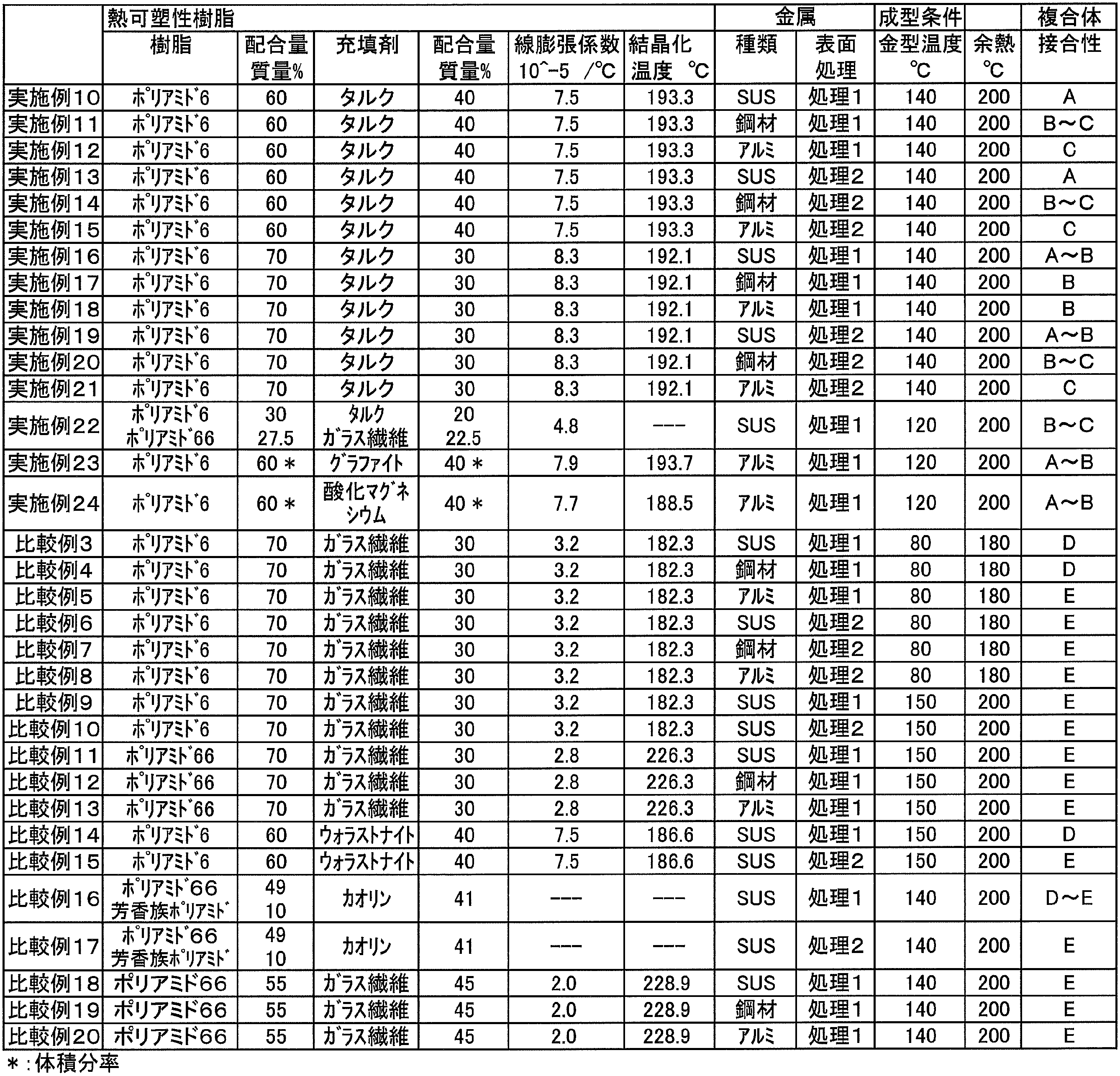
Claims (9)
- 熱可塑性樹脂組成物(A)と金属(B)とが接触接合した複合体であって、
前記熱可塑性樹脂組成物(A)は、熱可塑性樹脂と該熱可塑性樹脂の結晶化温度を3℃以上上昇させる無機充填材とを含む組成物であり、
前記金属(B)は、表面処理した金属である複合体。 - 前記熱可塑性樹脂は、ポリアミド樹脂である請求項1に記載の複合体。
- 前記無機充填材は、タルク、グラファイト、酸化マグネシウム、カオリン及び炭酸カルシウムからなる群より選ばれる少なくとも一種である請求項1または2記載の複合体。
- 前記無機充填材は、タルク、グラファイト及び酸化マグネシウムからなる群より選ばれる少なくとも一種である請求項1または2記載の複合体。
- 前記無機充填材の配合量は、前記熱可塑性樹脂組成物(A)中に、0.01質量%以上50質量%以下である請求項1~4のいずれか1つに記載の複合体。
- 前記金属(B)の表面処理は、その表面に微細な凹凸を形成する処理又は化学物質を固着させる処理である請求項1~5のいずれか1つに記載の複合体。
- 前記熱可塑性樹脂組成物(A)と前記金属(B)とが射出成形により接触接合されたものである請求項1~6のいずれか1つに記載の複合体。
- 前記熱可塑性樹脂組成物(A)の、前記熱可塑性樹脂組成物(A)と前記金属(B)との接合面に対して対向する面には、リブ、突起、穴、段差から選ばれた1種からなる収縮抑制構造が設けられている請求項1~7のいずれか1つに記載の複合体。
- 全体形状が管または棒状であり、樹脂と金属が多層構成をなしている請求項1~8のいずれか1つに記載の複合体。
Priority Applications (4)
| Application Number | Priority Date | Filing Date | Title |
|---|---|---|---|
| CN2012800143413A CN103429413A (zh) | 2011-03-25 | 2012-02-21 | 金属与热塑性树脂的复合体 |
| EP12763162.0A EP2689910A4 (en) | 2011-03-25 | 2012-02-21 | COMPOSITE BODY OF METAL AND A HEAT-RESISTANT RESIN |
| JP2013507261A JPWO2012132639A1 (ja) | 2011-03-25 | 2012-02-21 | 金属と熱可塑性樹脂の複合体 |
| US14/006,654 US20140010980A1 (en) | 2011-03-25 | 2012-02-21 | Composite of metal and thermoplastic resin |
Applications Claiming Priority (2)
| Application Number | Priority Date | Filing Date | Title |
|---|---|---|---|
| JP2011068450 | 2011-03-25 | ||
| JP2011-068450 | 2011-03-25 |
Publications (1)
| Publication Number | Publication Date |
|---|---|
| WO2012132639A1 true WO2012132639A1 (ja) | 2012-10-04 |
Family
ID=46930400
Family Applications (1)
| Application Number | Title | Priority Date | Filing Date |
|---|---|---|---|
| PCT/JP2012/054091 Ceased WO2012132639A1 (ja) | 2011-03-25 | 2012-02-21 | 金属と熱可塑性樹脂の複合体 |
Country Status (5)
| Country | Link |
|---|---|
| US (1) | US20140010980A1 (ja) |
| EP (1) | EP2689910A4 (ja) |
| JP (2) | JPWO2012132639A1 (ja) |
| CN (1) | CN103429413A (ja) |
| WO (1) | WO2012132639A1 (ja) |
Cited By (4)
| Publication number | Priority date | Publication date | Assignee | Title |
|---|---|---|---|---|
| WO2015022955A1 (ja) | 2013-08-12 | 2015-02-19 | 宇部興産株式会社 | 熱可塑性樹脂と金属との複合体 |
| JP2015057466A (ja) * | 2013-08-12 | 2015-03-26 | 宇部興産株式会社 | ポリアミドエラストマー組成物、及びそれを用いた成形体 |
| JP2018177867A (ja) * | 2017-04-05 | 2018-11-15 | 三菱エンジニアリングプラスチックス株式会社 | 金属接合用ポリアミド樹脂組成物、金属樹脂複合体および金属樹脂複合体の製造方法 |
| JP2022187378A (ja) * | 2021-06-07 | 2022-12-19 | 大成プラス株式会社 | 金属と樹脂の一体化複合体とその製造方法 |
Families Citing this family (12)
| Publication number | Priority date | Publication date | Assignee | Title |
|---|---|---|---|---|
| CN104552797B (zh) * | 2014-12-24 | 2017-02-01 | 苏州工业园区协利塑胶有限公司 | 一种环形注塑件保内圆圆度的加工模具 |
| CN104962972A (zh) * | 2015-07-22 | 2015-10-07 | 苏州道蒙恩电子科技有限公司 | 一种铝合金与树脂结合体的制造方法 |
| CN106894010B (zh) * | 2015-12-17 | 2019-10-11 | 比亚迪股份有限公司 | 金属表面处理组合物、金属-树脂复合体及其制备方法 |
| CN109715393B (zh) * | 2017-07-28 | 2020-11-03 | 东丽先端材料研究开发(中国)有限公司 | 一种热塑性树脂组合物与金属的接合体及其制造方法 |
| KR20200055762A (ko) | 2017-10-27 | 2020-05-21 | 미쯔이가가꾸가부시끼가이샤 | 금속/수지 복합 구조체 및 금속/수지 복합 구조체의 제조 방법 |
| EP3587065A1 (en) * | 2018-06-30 | 2020-01-01 | SABIC Global Technologies B.V. | Polyketone materials for nano-molding technology |
| CN110939650B (zh) * | 2018-09-25 | 2023-06-23 | 精工电子有限公司 | 结构体 |
| WO2020189501A1 (ja) * | 2019-03-20 | 2020-09-24 | 東洋紡株式会社 | ポリアミド樹脂組成物 |
| JPWO2020189502A1 (ja) | 2019-03-20 | 2020-09-24 | ||
| KR20200127486A (ko) * | 2019-05-02 | 2020-11-11 | 현대자동차주식회사 | 이종소재 일체화 구조체 및 일체화 방법 |
| EP3748046A1 (en) * | 2019-06-07 | 2020-12-09 | Arkema France | Method for producing metal-polymer composites |
| CN117484773B (zh) * | 2023-12-06 | 2024-08-02 | 沧州德安防爆特种工具制造有限公司 | 碳纤维基防爆双头呆扳手的制备方法 |
Citations (11)
| Publication number | Priority date | Publication date | Assignee | Title |
|---|---|---|---|---|
| JPH0551671A (ja) | 1991-08-21 | 1993-03-02 | Nikko Kyodo Co Ltd | 曲げ性及び応力緩和特性に優る電子機器用高力高導電性銅合金 |
| JPH0551671B2 (ja) * | 1989-02-02 | 1993-08-03 | Kunio Mori | |
| JP2003176403A (ja) * | 2001-09-25 | 2003-06-24 | Asahi Kasei Corp | 熱可塑性樹脂複合成形体 |
| JP2006315398A (ja) * | 2005-04-14 | 2006-11-24 | Taisei Plas Co Ltd | アルミニウム合金と樹脂の複合体とその製造方法 |
| JP2007182071A (ja) | 2005-12-08 | 2007-07-19 | Toray Ind Inc | アルミニウム合金と樹脂の複合体及びその製造方法 |
| JP3967104B2 (ja) | 2001-07-25 | 2007-08-29 | 大成プラス株式会社 | 金属と樹脂の複合体とその製造方法 |
| WO2010016485A1 (ja) * | 2008-08-06 | 2010-02-11 | 大成プラス株式会社 | 金属合金とポリアミド樹脂組成物の複合体とその製造方法 |
| JP4527196B2 (ja) | 2009-12-24 | 2010-08-18 | 東ソー株式会社 | 複合体およびその製造方法 |
| JP4541153B2 (ja) | 2002-12-16 | 2010-09-08 | コロナインターナショナル株式会社 | アルミニウム材と合成樹脂成形体の複合品の製造法及びその複合品 |
| JP2011156764A (ja) * | 2010-02-01 | 2011-08-18 | Taisei Plas Co Ltd | 金属とポリアミド樹脂組成物の複合体及びその製造方法 |
| JP2011213108A (ja) * | 2010-03-16 | 2011-10-27 | Ube Industries Ltd | 複合構造体 |
Family Cites Families (12)
| Publication number | Priority date | Publication date | Assignee | Title |
|---|---|---|---|---|
| US2174766A (en) * | 1932-12-12 | 1939-10-03 | Terwilliger Ivan Melville | Means for producing stereoscopic photographic effects |
| JP2763575B2 (ja) * | 1989-03-31 | 1998-06-11 | ポリプラスチックス株式会社 | ポリアルキレンアリレート樹脂組成物 |
| JP3231435B2 (ja) * | 1992-11-09 | 2001-11-19 | 日本ジーイープラスチックス株式会社 | 樹脂組成物 |
| US6313209B2 (en) * | 2000-02-18 | 2001-11-06 | Mitsubishi Engineering-Plastics Corporation | Polyamide resin composition and film produced from the same |
| EP1740651A1 (en) * | 2004-04-26 | 2007-01-10 | Borealis Technology Oy | Use |
| JP4515824B2 (ja) * | 2004-05-27 | 2010-08-04 | Ntn株式会社 | 高精度すべり軸受 |
| JP2006182071A (ja) * | 2004-12-27 | 2006-07-13 | Nissan Motor Light Truck Co Ltd | キャブチルト装置 |
| CN101341023B (zh) * | 2005-12-08 | 2012-05-30 | 大成普拉斯株式会社 | 铝合金与树脂的复合体及其制造方法 |
| EP2270098A1 (en) * | 2008-03-27 | 2011-01-05 | Ube Industries, Ltd. | Polyamide resin composition for film |
| JP5166978B2 (ja) * | 2008-06-05 | 2013-03-21 | 大成プラス株式会社 | 金属合金と樹脂の複合体の製造方法 |
| JP5554483B2 (ja) * | 2008-09-11 | 2014-07-23 | 大成プラス株式会社 | 金属と樹脂の複合体及びその製造方法 |
| US20120156473A1 (en) * | 2009-08-31 | 2012-06-21 | Kureha Corporation | Laminate and stretched laminate using the same |
-
2012
- 2012-02-21 US US14/006,654 patent/US20140010980A1/en not_active Abandoned
- 2012-02-21 EP EP12763162.0A patent/EP2689910A4/en not_active Withdrawn
- 2012-02-21 JP JP2013507261A patent/JPWO2012132639A1/ja active Pending
- 2012-02-21 CN CN2012800143413A patent/CN103429413A/zh active Pending
- 2012-02-21 WO PCT/JP2012/054091 patent/WO2012132639A1/ja not_active Ceased
-
2015
- 2015-07-07 JP JP2015136102A patent/JP5958615B2/ja not_active Expired - Fee Related
Patent Citations (11)
| Publication number | Priority date | Publication date | Assignee | Title |
|---|---|---|---|---|
| JPH0551671B2 (ja) * | 1989-02-02 | 1993-08-03 | Kunio Mori | |
| JPH0551671A (ja) | 1991-08-21 | 1993-03-02 | Nikko Kyodo Co Ltd | 曲げ性及び応力緩和特性に優る電子機器用高力高導電性銅合金 |
| JP3967104B2 (ja) | 2001-07-25 | 2007-08-29 | 大成プラス株式会社 | 金属と樹脂の複合体とその製造方法 |
| JP2003176403A (ja) * | 2001-09-25 | 2003-06-24 | Asahi Kasei Corp | 熱可塑性樹脂複合成形体 |
| JP4541153B2 (ja) | 2002-12-16 | 2010-09-08 | コロナインターナショナル株式会社 | アルミニウム材と合成樹脂成形体の複合品の製造法及びその複合品 |
| JP2006315398A (ja) * | 2005-04-14 | 2006-11-24 | Taisei Plas Co Ltd | アルミニウム合金と樹脂の複合体とその製造方法 |
| JP2007182071A (ja) | 2005-12-08 | 2007-07-19 | Toray Ind Inc | アルミニウム合金と樹脂の複合体及びその製造方法 |
| WO2010016485A1 (ja) * | 2008-08-06 | 2010-02-11 | 大成プラス株式会社 | 金属合金とポリアミド樹脂組成物の複合体とその製造方法 |
| JP4527196B2 (ja) | 2009-12-24 | 2010-08-18 | 東ソー株式会社 | 複合体およびその製造方法 |
| JP2011156764A (ja) * | 2010-02-01 | 2011-08-18 | Taisei Plas Co Ltd | 金属とポリアミド樹脂組成物の複合体及びその製造方法 |
| JP2011213108A (ja) * | 2010-03-16 | 2011-10-27 | Ube Industries Ltd | 複合構造体 |
Non-Patent Citations (1)
| Title |
|---|
| See also references of EP2689910A4 |
Cited By (8)
| Publication number | Priority date | Publication date | Assignee | Title |
|---|---|---|---|---|
| WO2015022955A1 (ja) | 2013-08-12 | 2015-02-19 | 宇部興産株式会社 | 熱可塑性樹脂と金属との複合体 |
| JP2015057466A (ja) * | 2013-08-12 | 2015-03-26 | 宇部興産株式会社 | ポリアミドエラストマー組成物、及びそれを用いた成形体 |
| JPWO2015022955A1 (ja) * | 2013-08-12 | 2017-03-02 | 宇部興産株式会社 | 熱可塑性樹脂と金属との複合体 |
| EP3034293A4 (en) * | 2013-08-12 | 2017-04-26 | UBE Industries, Ltd. | Composite body of thermoplastic resin and metal |
| US9975317B2 (en) | 2013-08-12 | 2018-05-22 | Ube Industries, Ltd. | Composite body of metal and thermoplastic resin |
| JP2018177867A (ja) * | 2017-04-05 | 2018-11-15 | 三菱エンジニアリングプラスチックス株式会社 | 金属接合用ポリアミド樹脂組成物、金属樹脂複合体および金属樹脂複合体の製造方法 |
| JP7011898B2 (ja) | 2017-04-05 | 2022-01-27 | 三菱エンジニアリングプラスチックス株式会社 | 金属接合用ポリアミド樹脂組成物、金属樹脂複合体および金属樹脂複合体の製造方法 |
| JP2022187378A (ja) * | 2021-06-07 | 2022-12-19 | 大成プラス株式会社 | 金属と樹脂の一体化複合体とその製造方法 |
Also Published As
| Publication number | Publication date |
|---|---|
| JP2015214159A (ja) | 2015-12-03 |
| EP2689910A4 (en) | 2015-03-11 |
| JP5958615B2 (ja) | 2016-08-02 |
| US20140010980A1 (en) | 2014-01-09 |
| CN103429413A (zh) | 2013-12-04 |
| EP2689910A1 (en) | 2014-01-29 |
| JPWO2012132639A1 (ja) | 2014-07-24 |
Similar Documents
| Publication | Publication Date | Title |
|---|---|---|
| JP5958615B2 (ja) | 金属と熱可塑性樹脂の複合体 | |
| US10577478B2 (en) | Polyamide moulding composition and multi-layered structure made therefrom | |
| JP7180738B2 (ja) | 含フッ素共重合体組成物、その製造方法、および成形体 | |
| EP3112421B1 (en) | Polyamide resin composition for molded article to be in contact with high-pressure hydrogen, and molded article obtained therefrom | |
| CN103286910B (zh) | 一种金属树脂一体化成型方法和一种金属树脂复合体 | |
| CN103286908B (zh) | 一种金属树脂一体化成型方法和一种金属树脂复合体 | |
| WO2009151099A1 (ja) | アルミ・樹脂射出一体成形品及びその製造方法 | |
| TWI733724B (zh) | 用以於金屬表面作塑膠覆蓋成形(overmolding)之方法及塑膠-金屬混合部件 | |
| KR20220140479A (ko) | 유리섬유 강화 수지 조성물 및 유리섬유 강화 수지 성형품 | |
| EP2650321B1 (en) | Process for welding of two polyamide parts | |
| JP6521011B2 (ja) | 熱可塑性樹脂と金属との複合体 | |
| EP3951034A1 (en) | Glass direct roving and glass filament-reinforced thermoplastic resin pellets | |
| CN113226737A (zh) | 金属纤维强化塑料复合材料 | |
| JP6511262B2 (ja) | 樹脂金属複合体及びその製造方法 | |
| JP2009179675A5 (ja) | ||
| KR102588980B1 (ko) | 폴리아미드 조성물 및 그의 도금 용도 | |
| KR102401427B1 (ko) | 복합 적층체 및 그의 제조 방법 | |
| JP2013244653A (ja) | 熱可塑性樹脂組成物と金属の複合体 | |
| US20240026100A1 (en) | Surface-modifying sheet, laminate, surface-modified member, coated article, method for producing surface-modified member, and method for producing coated article | |
| JP7395923B2 (ja) | プリプレグと接合するためのポリアミド樹脂フィルム、及び積層体 | |
| JP6310213B2 (ja) | 金属と樹脂との複合体及びその製造方法 | |
| KR20210106411A (ko) | 플루오르화 공중합체 조성물 | |
| KR20220018574A (ko) | 금속-중합체 복합체의 제조 방법 |
Legal Events
| Date | Code | Title | Description |
|---|---|---|---|
| 121 | Ep: the epo has been informed by wipo that ep was designated in this application |
Ref document number: 12763162 Country of ref document: EP Kind code of ref document: A1 |
|
| ENP | Entry into the national phase |
Ref document number: 2013507261 Country of ref document: JP Kind code of ref document: A |
|
| WWE | Wipo information: entry into national phase |
Ref document number: 14006654 Country of ref document: US |
|
| NENP | Non-entry into the national phase |
Ref country code: DE |
|
| REEP | Request for entry into the european phase |
Ref document number: 2012763162 Country of ref document: EP |
|
| WWE | Wipo information: entry into national phase |
Ref document number: 2012763162 Country of ref document: EP |