WO2012127657A1 - ワークの欠陥検出装置 - Google Patents
ワークの欠陥検出装置 Download PDFInfo
- Publication number
- WO2012127657A1 WO2012127657A1 PCT/JP2011/057007 JP2011057007W WO2012127657A1 WO 2012127657 A1 WO2012127657 A1 WO 2012127657A1 JP 2011057007 W JP2011057007 W JP 2011057007W WO 2012127657 A1 WO2012127657 A1 WO 2012127657A1
- Authority
- WO
- WIPO (PCT)
- Prior art keywords
- defect
- workpiece
- work
- imaging device
- outer peripheral
- Prior art date
- Legal status (The legal status is an assumption and is not a legal conclusion. Google has not performed a legal analysis and makes no representation as to the accuracy of the status listed.)
- Ceased
Links
Images



Classifications
-
- H—ELECTRICITY
- H04—ELECTRIC COMMUNICATION TECHNIQUE
- H04N—PICTORIAL COMMUNICATION, e.g. TELEVISION
- H04N7/00—Television systems
- H04N7/18—Closed-circuit television [CCTV] systems, i.e. systems in which the video signal is not broadcast
-
- G—PHYSICS
- G01—MEASURING; TESTING
- G01N—INVESTIGATING OR ANALYSING MATERIALS BY DETERMINING THEIR CHEMICAL OR PHYSICAL PROPERTIES
- G01N21/00—Investigating or analysing materials by the use of optical means, i.e. using sub-millimetre waves, infrared, visible or ultraviolet light
- G01N21/84—Systems specially adapted for particular applications
- G01N21/88—Investigating the presence of flaws or contamination
- G01N21/95—Investigating the presence of flaws or contamination characterised by the material or shape of the object to be examined
- G01N21/9515—Objects of complex shape, e.g. examined with use of a surface follower device
-
- G—PHYSICS
- G01—MEASURING; TESTING
- G01N—INVESTIGATING OR ANALYSING MATERIALS BY DETERMINING THEIR CHEMICAL OR PHYSICAL PROPERTIES
- G01N21/00—Investigating or analysing materials by the use of optical means, i.e. using sub-millimetre waves, infrared, visible or ultraviolet light
- G01N21/84—Systems specially adapted for particular applications
- G01N21/88—Investigating the presence of flaws or contamination
- G01N21/95—Investigating the presence of flaws or contamination characterised by the material or shape of the object to be examined
- G01N21/952—Inspecting the exterior surface of cylindrical bodies or wires
Definitions
- the present invention relates to a technique for detecting a defect present on the outer peripheral surface of a workpiece.
- Patent Document 1 discloses a technique for inspecting a surface defect of a camshaft.
- the surface is divided into a plurality of inspection areas in consideration of the application of the cam, and a dedicated optical device is used for each inspection area, and the reference used for defect determination is changed according to each inspection area. Therefore, the optimum inspection conditions for the camshaft to be inspected are adopted. In this way, a defect inspection that takes into consideration the unique properties of the inspection object, such as usage conditions, is realized.
- Patent Document 2 discloses a technique for inspecting a defect on a workpiece surface including a curved surface at a peripheral edge.
- a defect existing in a curved surface portion is recognized by changing the image processing conditions in consideration of the density of the curved surface portion that is an inclined surface with respect to the imaging means.
- An object of the present invention is to provide a technique for improving the accuracy of detecting defects on the outer peripheral surface of a workpiece.
- a workpiece defect detection apparatus is a device for detecting defects existing on the outer peripheral surface of a workpiece, and supports the workpiece and holds the workpiece rotated at a predetermined angle by the jig.
- An imaging device that images the outer peripheral surface of a work held in a state rotated at a predetermined angle; and a control device that processes an image obtained by the imaging device and determines a defect.
- Information on the shape of the outer peripheral surface of the workpiece, and information on the positional relationship between the imaging portion of the workpiece by the imaging device and the imaging device at each rotation angle are stored, and when determining the defect, Use information.
- control device determines the defect by comparing a threshold value stored in advance with a size of a defect included in an image obtained by the imaging device.
- the information on the shape of the outer peripheral surface of the workpiece and the information on the positional relationship between the imaging portion of the workpiece by the imaging device and the imaging device at each rotation angle are used. It is preferable to change the threshold used in the determination according to the position of the defect.
- the defect detection apparatus 1 is an apparatus for detecting a defect D existing on the outer peripheral surface of the work W, and inspects the entire outer periphery by rotating the work W and imaging the outer peripheral surface.
- the defect D is a defect that appears on the surface of the workpiece W, and is, for example, a concave defect such as a cast hole, a crack, or a scratch caused by machining.
- the defect D is determined to be acceptable / unacceptable depending on its size, and the workpiece W having the defect D having an unacceptable size is processed as a defective product.
- the workpiece W has a curvature in the circumferential direction, and the outer circumferential surface is formed as a curved surface.
- the workpiece W includes an axis R, and is configured as an axial member that can rotate around the axis R.
- the workpiece W is a cylindrical member whose distance from the axis R to the outer peripheral surface is constant, a cam shaft whose distance from the axis R to the outer peripheral surface changes depending on the angle, and the like.
- the outer peripheral surface of the workpiece W may be formed as a flat surface as long as it can rotate around the axis R, and may be a prism member, for example.
- the defect detection apparatus 1 controls the rotation of the jig
- the jig 10 holds the workpiece W in a predetermined position, and supports the workpiece W rotatably about the axis R.
- the jig 10 includes a motor 11 for rotating the workpiece W.
- the output shaft of the motor 11 is connected to the axis R of the workpiece W, and the workpiece W rotates about the axis R by driving the motor 11. Further, the motor 11 is provided with an encoder 12, and the rotation angle of the motor 11 (the rotation angle of the shaft R) can be detected.
- the motor 11 and the encoder 12 are electrically connected to the control device 30.
- the motor 11 is driven by a control signal from the control device 30, and a detection signal related to the rotation angle of the motor 11 by the encoder 12 is transmitted to the control device 30.
- the control device 30 detects the tilt angle of the workpiece W based on the detection signal from the encoder 12, and transmits the control signal to the motor 11 to drive and stop the workpiece W, thereby rotating the workpiece W to a predetermined angle. It is possible to hold in the state.
- the imaging device 20 captures the surface (outer peripheral surface) of the workpiece W and acquires image data Img.
- the imaging device 20 includes a camera 21 and a surgical light 22.
- the camera 21 captures a predetermined visual field range on the surface of the workpiece W to generate image data Img.
- the camera 21 is fixed at a position away from the axis R, which is the rotation center of the workpiece W, by a predetermined distance, and cannot move with respect to the axis R.
- the surgical light 22 is a dome-shaped illumination device and illuminates the surface of the workpiece W.
- the surgical light 22 is constituted by a plurality of illumination groups arranged so as to surround the camera 21. In the imaging device 20, in a state in which the work W is illuminated by the surgical light 22, the camera 21 captures the image data Img.
- the camera 21 and the surgical light 22 are electrically connected to the control device 30.
- the lighting operation of the surgical light 22 is controlled by the control signal from the control device 30 and the imaging operation by the camera 21 is controlled. Then, the image data Img acquired by the camera 21 is transmitted to the control device 30.
- the image data Img of the workpiece W is acquired by the camera 21 while the workpiece W is held at a predetermined inclination angle by the jig 10. In this manner, the workpiece W is imaged by the camera 21 in a state where the rotation angle of the workpiece W is reliably determined by the jig 10. Thereby, the distance between the camera 21 and the surface of the workpiece W is fixed for each rotation angle of the workpiece W, and the imaging range of the image data Img at each rotation angle is fixed.
- the image distortion in the circumferential direction due to the curvature of the outer peripheral surface of the workpiece W is taken into account according to the posture of the workpiece W. This makes it possible to take into account the shape distortion of the defect D included in the image data Img when picking up the curved surface portion as a flat image.
- the control device 30 is connected to the jig 10 and the imaging device 20, controls the operation of the motor 11, the camera 21, and the surgical light 22, and synchronizes the rotation of the workpiece W with the imaging operation by the camera 21, Data (rotation angle of the workpiece W and image data Img) acquired by the encoder 12 and the camera 21 are received, and analysis and image processing are performed based on these data. Moreover, the control apparatus 30 has memorize
- the information related to the shape of the outer peripheral surface of the workpiece W is information regarding the positional relationship including the distance and angle from the axis R of the workpiece W to the outer peripheral surface, and is unambiguous with respect to the rotation angle of the axis R and the workpiece W.
- work W determined is pointed out.
- the control device 30 stores the geometric distance (positional relationship) between the imaging portion of the workpiece W included in the visual field range of the camera 21 and the camera 21 at each rotation angle of the workpiece W. That is, the control device 30 stores the degree of image distortion in each part of the workpiece W in the image data Img, and stores information on the shape distortion corresponding to the position of the defect D existing in the image data Img. Yes.
- control device 30 stores a threshold value Th corresponding to the image distortion of the workpiece W at each rotation angle of the workpiece W, and the workpiece W when the size of the defect D in the image data Img exceeds the threshold value Th. It is determined that there is a defect having an unacceptable size on the surface.
- the control device 30 uses information related to the shape of the outer peripheral surface of the workpiece W and information related to the positional relationship between the imaging portion of the workpiece W included in the visual field range of the camera 21 and the camera 21 at each rotation angle of the workpiece W. Then, the defect determination is performed by comparing the threshold Th with the size of the defect D.
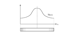
- Threshold value Th is set according to the magnitude of image distortion of each image data Img.
- the threshold value Th is directly set to the camera 21 and is set to be large in the central portion where the distortion is small, becomes an end portion of the image field of the camera 21, and has a distortion degree as compared with the central portion. The large end is set small.
- the threshold value Th (x) set in this way is set for each image data Img. As shown in FIG. 2, the value Th (x) has a value corresponding to the circumferential position (x) in the image data Img. Is set.
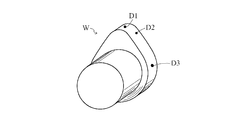
- the defect detection process when the workpiece W including the defects D1 to D3 is inspected using the defect detection apparatus 1 will be described.
- the workpiece W is a cam shaft, and the surface of the cam portion of the cam shaft is inspected.
- Defects D1 to D3 are representative examples of defects existing on the surface of the cam portion of the workpiece W.
- the defect D1 is a circular defect appearing at the top, and the defect D2 is located at a position shifted by about 40 degrees from the defect D1.
- An existing circular small defect, the defect D3, is a circular defect appearing on the side. It is assumed that the defects D1 and D3 are unacceptably large defects, and the defect D2 is an unacceptably large defect.
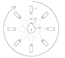
- FIG. 4 shows a view in which the workpiece W is fixed and the camera 21 is rotated 45 degrees around the axis R of the workpiece W.
- the image data Img1 to Img8 is obtained by the imaging device 20.
- These image data Img1 to Img8 are acquired as a plan view in which the outer peripheral surface of the workpiece W is sequentially imaged along the circumferential direction.
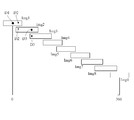
- the circumferential direction of the workpiece W is displayed as the left-right direction, and the apex of the cam portion of the workpiece W is displayed as (0).
- the control device 30 compares the position and size of the defects D1 to D3 appearing in the image data Img1 to Img8 with the threshold value Th to determine whether the defect is acceptable or unacceptable.
- a threshold value Th (x) is set, and according to the size of the defects D1 to D3 and the circumferential position (x), Defect determination is performed by comparing the threshold value Th (x) with the magnitude, and it is determined that the defects D1 and D3 are unacceptable size defects and the defect D2 is an acceptable size defect.
- the position (x) in the circumferential direction of each defect D is determined as the center position in the circumferential direction.
- the size of each defect D is determined as the length in the circumferential direction.
- the size in the longitudinal direction is determined based on the distortion information of the image data Img stored in the control device 30. Judging by using the diameter and the center position, it is regarded as a circular shape having a major axis of a shape defect) as a diameter.
- the threshold value Th (x) considering geometric image distortion is set, and the positions (x) and the sizes of the defects D1 to D3 included in the image are set.
- the threshold value Th (x) it is possible to accurately detect a defect appearing on the outer peripheral surface of the workpiece W having a curvature, particularly a defect appearing at an end portion having a large image distortion. 1 reliability can be improved.
- the dimension of the defect D appearing in the image data Img is used as it is, analysis on the image data Img is unnecessary, and the load of image processing can be reduced.
- these series of image data include overlapping portions between adjacent image data. Will exist. In such an overlapping portion, the same defect existing near the boundary is imaged, but determination is made at a position where the degree of distortion is smaller by making determination based on image data on the side where the distance from the end is larger. And the accuracy of defect detection is increased.
- the defect D3 present at the end of the image data Img2 shown in FIG. 5 appears overlapping the end of the image data Img3.
- the distance between the center of the defect D3 (center position in the circumferential direction) and each end portion is measured, and the size of the defect D3 is determined using the larger distance (image data Img3 in this embodiment).
- the influence of the image distortion of the defect D3 can be reduced. That is, by employing the image data Img having a smaller angle with respect to the camera 21, the degree of image distortion caused by the curvature can be reduced. In this way, the detection accuracy of the defect D appearing at the end of each image data Img can be improved.
- the threshold Th is changed in accordance with the circumferential coordinate (x), in other words, the threshold Th (x) is used as a variable of the circumferential position (x).
- the form which handled and performs defect judgment was shown.
- a defect detection apparatus that performs defect determination with a threshold value Th as a constant value will be described with reference to FIGS.
- the shape of the defect D is corrected in consideration of image distortion, and the defect is determined after fitting to the actual shape. Specifically, it is as follows.
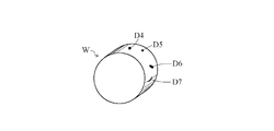
- the workpiece W is a cylinder including the defects D4 to D7, and eight pieces of image data Img1 to Img8 are imaged by the imaging device 20 while the workpiece W is similarly rotated 45 degrees by the jig 10.
- Defects D4 to D7 are representative examples of defects present on the surface of the cam portion of the workpiece W.
- the defect D4 is a circular defect that appears at the top, and the defect D5 is at a position that is out of phase by about 40 degrees with respect to the defect D4.
- An existing circular small defect the defect D6 is an elliptical defect appearing on the side, and the defect D7 is a crescent shaped defect appearing on the side. It is assumed that the defects D4, D6, and D7 are unacceptable sizes, the defect D5 is an acceptable size, and the defects D6 and D7 are inclined with respect to the circumferential direction.
- the image data Img1 to Img8 is obtained by the imaging device 20.
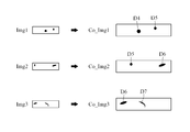
- the control device 30 corrects image distortion for the image data Img1 to Img8 acquired in this way, and processes the outer peripheral surface of the workpiece W as a plan view developed along the circumferential direction. That is, in this embodiment, in order to recognize the net shape of the defect D of the workpiece W, the image data Img is corrected and processed.
- the control device 30 stores information related to the shape of the workpiece W (the shape of the outer peripheral surface) stored in the control device 30 in advance, the imaging part of the workpiece by the camera 21 and the camera at each rotation angle of the workpiece W.
- the image distortion is corrected for the image data Img1 to Img8 using the information regarding the positional relationship with the image data 21.
- each of the image data Img1 to Img8 acquired by the camera 21 is corrected, and a corrected image Co_Img1 having an actual length in the circumferential direction of the workpiece W within the visual field range of the camera 21.
- ⁇ Co_Img8 is generated.
- the shapes of the defects D4 to D7 existing in the corrected images Co_Img1 to Co_Img8 generated in this way also appear as net shapes. That is, the defect determination is performed by comparing the actual size of the defect in the corrected images Co_Img1 to Co_Img8 with the threshold Th, and the defect D4, D6, and D7 are unacceptable in size, and the defect D5 is acceptable. Determined as a size defect.
- the image data Img1 to Img8 are subjected to geometric image correction, and the sizes of the defects D4 to D7 included in the corrected image are compared with the threshold Th. It is possible to accurately detect defects appearing on the outer peripheral surface of the workpiece W having a curvature, and the reliability of the defect detection apparatus 1 can be improved. In the case of this embodiment, since the actual dimension of the defect D is calculated and the defect determination is performed, a more strict defect determination is possible.
- an ellipse that includes the outline of the defect recognizes as a shape (or rectangular shape), and compares and determines the major axis (or long side) and threshold value Th.
- the defect D7 shown in the drawing is a crescent-shaped irregular defect
- the size of the major axis of the ellipse that encloses the defect D7 or the size of the long side of the rectangle is recognized as the size of the defect. In this way, erroneous determination that can occur depending on the shape and direction of the irregular defect can be avoided.
- the imaging device 20 intermittently photographs the workpiece W held at a predetermined angle by the jig 10, but is not limited to this, and the imaging device 20 continuously photographs the workpiece W while rotating the workpiece W. May be.
- the size of the defect D can be detected at the position where the camera 21 faces the defect D, and the influence of image distortion can be minimized.
- the present invention can be suitably used for defect inspection when the outer peripheral surface of the workpiece has a curvature.
Landscapes
- Physics & Mathematics (AREA)
- Health & Medical Sciences (AREA)
- Life Sciences & Earth Sciences (AREA)
- Chemical & Material Sciences (AREA)
- Analytical Chemistry (AREA)
- Biochemistry (AREA)
- General Health & Medical Sciences (AREA)
- General Physics & Mathematics (AREA)
- Immunology (AREA)
- Pathology (AREA)
- Engineering & Computer Science (AREA)
- Multimedia (AREA)
- Signal Processing (AREA)
- Investigating Materials By The Use Of Optical Means Adapted For Particular Applications (AREA)
- Length Measuring Devices By Optical Means (AREA)
Abstract
Description
以下、図面を参照して、欠陥検出装置の第一実施形態について説明する。
欠陥検出装置1は、ワークWの外周面に存在する欠陥Dを検出するための装置であり、ワークWを回転させて外周面を撮像することによって外周全周を検査する。欠陥Dは、ワークWの表面に現れる欠陥であり、例えば機械加工によって生じる鋳巣、クラック、傷等の凹欠陥である。欠陥Dは、その大きさに応じて許容できる/許容できないが判定され、許容できない大きさの欠陥Dを有するワークWは不良品として処理される。
モータ11の出力軸は、ワークWの軸Rに接続されており、モータ11を駆動することによってワークWが軸Rを中心に回転する。また、モータ11にはエンコーダ12が付設され、モータ11の回転角(軸Rの回転角)を検出可能である。
カメラ21は、ワークWの表面のうち、所定の視野範囲内を撮影して画像データImgを生成する。カメラ21は、ワークWの回転中心である軸Rと所定距離だけ離れた位置に固定されており、軸Rに対して移動不能である。
無影灯22は、ドーム型の照明装置であり、ワークWの表面を照明する。無影灯22は、カメラ21の周囲を取り囲むように配置される複数の照明群によって構成される。撮像装置20では、無影灯22でワークWを照明した状態で、カメラ21による撮影を行い、画像データImgを取得する。
このような条件でワークWを撮像することによって、カメラ21で画像データImgを取得する際に、ワークWの姿勢に応じてワークWの外周面の曲率に起因する周方向の画像歪みを考慮することが可能となり、曲面部分を平面的な画像としてピックアップする際に画像データImgに含まれる欠陥Dの形状歪みを考慮することが可能となる。
また、制御装置30は、ワークWの形状(外周面の形状)に関する情報を記憶している。このワークWの外周面の形状に関する情報とは、ワークWの軸Rから外周面までの距離及び角度を含む位置関係に関する情報であって、軸R及びワークWの回転角度に対して一義的に決定されるワークWの外周形状に関する情報を指す。さらに、制御装置30は、ワークWの各回転角度における、カメラ21の視野範囲内に含まれるワークWの撮像部位とカメラ21との幾何学的な距離(位置関係)を記憶している。すなわち、制御装置30には、画像データImgにおけるワークWの各部位における画像歪み度合いが記憶されており、画像データImg内に存在する欠陥Dの位置に応じた形状歪みについての情報が記憶されている。
制御装置30は、ワークWの外周面の形状に関する情報、及び、ワークWの各回転角度における、カメラ21の視野範囲内に含まれるワークWの撮像部位とカメラ21との位置関係に関する情報を利用して、閾値Thと欠陥Dの大きさとを比較して欠陥判定を行う。
欠陥D1~D3は、ワークWにおけるカム部の表面に存在する欠陥の代表例であり、欠陥D1は頂部に現れる円形の欠陥、欠陥D2は欠陥D1に対して40度程度位相がずれた位置に存在する円形の小型欠陥、欠陥D3は側部に現れる円形の欠陥とする。なお、欠陥D1・D3は許容できない大きさの欠陥であり、欠陥D2は許容できる大きさの欠陥であるものとする。
図6に示すように、それぞれの画像データImg1~Img8における画像歪みを考慮して、閾値Th(x)を設定し、欠陥D1~D3の大きさ及び周方向の位置(x)に応じて、閾値Th(x)との大小を比較することによって欠陥判定が行われ、欠陥D1・D3は許容できない大きさの欠陥、欠陥D2は許容できる大きさの欠陥であると判定される。
このとき、楕円形状、三日月形状、曲線形状等の非円形の欠陥Dを検出する場合は、制御装置30に記憶される画像データImgの歪み情報に基づいて、長手方向の大きさ(例えば、楕円形状の欠陥における長径)を直径とする円形状とみなし、その直径及び中心位置を用いて判定する。
本実施形態の場合は、画像データImgに現れる欠陥Dの寸法をそのまま利用するため、画像データImgに対する解析が不要であり、画像処理の負荷を低減できる。
このような場合、欠陥D3の中心(周方向の中心位置)とそれぞれの端部との距離を測定し、距離が大きい方(本実施形態では画像データImg3)を用いて欠陥D3の大きさを判定することで、欠陥D3の画像歪みによる影響を低減できる。つまり、カメラ21に対する角度が小さい方の画像データImgを採用することによって、曲率に起因する画像歪みの度合いを低減できる。このようにして、各画像データImgの端部に現れる欠陥Dの検出精度を向上できる。
以上の第一実施形態では、図2に示すように、閾値Thを周方向の座標(x)に応じて変化させて、言い換えれば閾値Th(x)を周方向の位置(x)の変数として扱って欠陥判定を行う形態を示した。
以下では、図7~図9を用いて、欠陥検出装置の第二実施形態として、閾値Thを一定値として欠陥判定を行う欠陥検出装置について説明する。本実施形態では、欠陥Dの形状を、画像歪みを考慮して補正して、実形状にフィッティングした上で欠陥の判定を行う。具体的には、以下の通りである。
欠陥D4~D7は、ワークWのカム部の表面に存在する欠陥の代表例であり、欠陥D4は頂部に現れる円形の欠陥、欠陥D5は欠陥D4に対して40度程度位相がずれた位置に存在する円形の小型欠陥、欠陥D6は側部に現れる楕円形の欠陥、欠陥D7は、側部に現れる三日月形状の欠陥とする。なお、欠陥D4・D6・D7は許容できない大きさの欠陥であり、欠陥D5は許容できる大きさの欠陥であるものとし、欠陥D6・D7は周方向に対して傾斜しているものとする。
制御装置30では、このように取得された画像データImg1~Img8に対して画像歪みの補正を行い、ワークWの外周面を周方向に沿って展開した平面図として処理する。つまり、本実施形態では、ワークWの欠陥Dの正味形状を認識するために、画像データImgを補正して処理する。
この場合、制御装置30は、制御装置30に予め記憶されている、ワークWの形状(外周面の形状)に関する情報や、ワークWの各回転角度における、カメラ21によるワークの撮像部位と当該カメラ21との位置関係に関する情報を用いて、画像データImg1~Img8に対する画像歪みの補正を行う。
このようにして生成される補正画像Co_Img1~Co_Img8内に存在する欠陥D4~D7の形状も正味の形状として現れる。すなわち、この補正画像Co_Img1~Co_Img8内での欠陥の実際の大きさと閾値Thとを比較することで欠陥判定が実施され、欠陥D4・D6・D7は許容できない大きさの欠陥、欠陥D5は許容できる大きさの欠陥として判定される。
本実施形態の場合は、欠陥Dの実寸法を算出して欠陥判定を行うため、より厳密な欠陥判定が可能である。
例えば、図に示す欠陥D7は、三日月形状の異形の欠陥であるため、欠陥D7を内包する楕円の長径の大きさ又は長方形の長辺の大きさを欠陥の大きさとして認識する。このように、異形の欠陥の形状、方向によって生じ得る誤判定を回避できる。
10 治具
20 撮像装置
30 制御装置
W ワーク
R 軸
D 欠陥
Img 画像データ
Claims (4)
- ワークの外周面に存在する欠陥を検出する装置であって、
前記ワークを支持するとともに、所定角度に回転した状態に保持する治具と、
前記治具によって所定角度に回転した状態に保持されたワークの外周面を撮像する撮像装置と、
前記撮像装置によって得られる画像を処理し、欠陥を判定する制御装置と、を具備し、
前記制御装置は、前記ワークの外周面の形状に関する情報、及び、各回転角度における、前記撮像装置によるワークの撮像部位と当該撮像装置との位置関係に関する情報を記憶しており、前記欠陥を判定する際に、これらの情報を利用するワークの欠陥検出装置。 - 前記制御装置は、予め記憶した閾値と前記撮像装置によって得られる画像に含まれる欠陥の大きさとを比較することによって、前記欠陥を判定する請求項1に記載のワークの欠陥検出装置。
- 前記ワークの外周面の形状に関する情報、及び、各回転角度における、前記撮像装置によるワークの撮像部位と当該撮像装置との位置関係に関する情報を用いて、前記欠陥の判定の際に用いる閾値を当該欠陥の位置に応じて変更する請求項2に記載の欠陥検出装置。
- 前記ワークの外周面の形状に関する情報、及び、各回転角度における、前記撮像装置によるワークの撮像部位と当該撮像装置との位置関係に関する情報を用いて、前記撮像装置によって得られる画像を補正し、前記欠陥の実形状を用いて判定する請求項1又は2に記載の欠陥検出装置。
Priority Applications (4)
| Application Number | Priority Date | Filing Date | Title |
|---|---|---|---|
| US14/006,435 US9247213B2 (en) | 2011-03-23 | 2011-03-23 | Apparatus for detecting defect of work |
| CN201180069466.1A CN103460028B (zh) | 2011-03-23 | 2011-03-23 | 工件的缺陷检测装置 |
| PCT/JP2011/057007 WO2012127657A1 (ja) | 2011-03-23 | 2011-03-23 | ワークの欠陥検出装置 |
| JP2013505726A JP5655936B2 (ja) | 2011-03-23 | 2011-03-23 | ワークの欠陥検出装置 |
Applications Claiming Priority (1)
| Application Number | Priority Date | Filing Date | Title |
|---|---|---|---|
| PCT/JP2011/057007 WO2012127657A1 (ja) | 2011-03-23 | 2011-03-23 | ワークの欠陥検出装置 |
Publications (1)
| Publication Number | Publication Date |
|---|---|
| WO2012127657A1 true WO2012127657A1 (ja) | 2012-09-27 |
Family
ID=46878850
Family Applications (1)
| Application Number | Title | Priority Date | Filing Date |
|---|---|---|---|
| PCT/JP2011/057007 Ceased WO2012127657A1 (ja) | 2011-03-23 | 2011-03-23 | ワークの欠陥検出装置 |
Country Status (4)
| Country | Link |
|---|---|
| US (1) | US9247213B2 (ja) |
| JP (1) | JP5655936B2 (ja) |
| CN (1) | CN103460028B (ja) |
| WO (1) | WO2012127657A1 (ja) |
Cited By (1)
| Publication number | Priority date | Publication date | Assignee | Title |
|---|---|---|---|---|
| JP2019523424A (ja) * | 2016-08-01 | 2019-08-22 | ショット シュヴァイツ アー・ゲーSCHOTT Schweiz AG | 透明なボディの光学検査を行う方法および装置 |
Families Citing this family (17)
| Publication number | Priority date | Publication date | Assignee | Title |
|---|---|---|---|---|
| US20130120557A1 (en) * | 2011-11-14 | 2013-05-16 | Microscan Systems, Inc. | Part inspection system |
| CN107150030A (zh) * | 2017-06-01 | 2017-09-12 | 温州大学 | 冷镦机成品表面形状在线智能检测装置 |
| CN108872244A (zh) * | 2018-05-08 | 2018-11-23 | 无锡九霄科技有限公司 | 一种基于线性相机的轴类部件外观检测方法 |
| IT201800005752A1 (it) * | 2018-05-28 | 2019-11-28 | Procedimento di controllo qualità superficiale ed apparato. | |
| US10408612B1 (en) * | 2018-06-27 | 2019-09-10 | Toyota Motor Engineering & Manufacturing North America, Inc. | Apparatus for non-contact optical evaluation of camshaft lobe surface roughness |
| CN109164110B (zh) * | 2018-08-24 | 2023-11-14 | 河北工业职业技术学院 | 滚子表面缺陷检测系统 |
| CN109100361A (zh) * | 2018-09-05 | 2018-12-28 | 深圳市盛世智能装备有限公司 | 一种工件缺陷检测设备 |
| WO2020133542A1 (zh) * | 2018-12-29 | 2020-07-02 | 深圳配天智能技术研究院有限公司 | 检测装置及检测方法 |
| CN110412052B (zh) * | 2019-08-12 | 2022-02-15 | 艾尔玛科技股份有限公司 | 一种曲面热压印质量检测方法及系统 |
| CN114641684A (zh) | 2019-08-30 | 2022-06-17 | 康宁股份有限公司 | 用于蜂窝体检查的系统和方法 |
| CN112824874A (zh) * | 2019-11-20 | 2021-05-21 | 泰科电子(上海)有限公司 | 线缆检测设备 |
| CN110865083A (zh) * | 2019-12-04 | 2020-03-06 | 深圳市汇万川塑胶薄膜有限公司 | 一种产品外观缺陷检测中环境与灯光的改进检测方法 |
| US20210194226A1 (en) * | 2019-12-20 | 2021-06-24 | Frisimos, Ltd. | System and method for removing a protective shield from an electrical cable |
| EP4153533B1 (en) * | 2020-05-22 | 2025-02-05 | Fraunhofer USA, Inc. | Systems and methods for synthesizing a diamond using machine learning |
| CN113376180A (zh) * | 2021-06-09 | 2021-09-10 | 深圳中科飞测科技股份有限公司 | 检测方法及检测设备 |
| CN113484330B (zh) * | 2021-07-05 | 2023-08-04 | 刘刚 | 一种高效率多方位产品检测设备 |
| JP7608997B2 (ja) * | 2021-07-21 | 2025-01-07 | トヨタ自動車株式会社 | 異常検査システム、異常検査方法及びプログラム |
Citations (6)
| Publication number | Priority date | Publication date | Assignee | Title |
|---|---|---|---|---|
| JPH01229946A (ja) * | 1988-03-10 | 1989-09-13 | Toyota Motor Corp | クランクシャフトの傷剥離の有無判定方法 |
| JPH01277743A (ja) * | 1988-04-28 | 1989-11-08 | Yasunaga:Kk | カムシヤフトの表面検査装置 |
| JPH0213836A (ja) * | 1988-06-30 | 1990-01-18 | Daihatsu Motor Co Ltd | カム表面の検査装置 |
| JPH03293542A (ja) * | 1990-03-05 | 1991-12-25 | Mazda Motor Corp | カムシャフトの表面欠陥検査方法 |
| JPH04132906A (ja) * | 1990-09-25 | 1992-05-07 | Mazda Motor Corp | カムシャフトの表面欠陥検査方法 |
| JP2008164532A (ja) * | 2006-12-28 | 2008-07-17 | Nippon Syst Design Kk | 表面検査装置および表面検査方法 |
Family Cites Families (17)
| Publication number | Priority date | Publication date | Assignee | Title |
|---|---|---|---|---|
| US4226539A (en) * | 1976-12-24 | 1980-10-07 | Hitachi, Ltd. | Cylindrical body appearance inspection apparatus |
| DE3027373A1 (de) * | 1979-07-20 | 1981-03-19 | Hitachi, Ltd., Tokyo | Verfahren und einrichtung zur oberflaechenpruefung |
| JP2839196B2 (ja) * | 1989-10-26 | 1998-12-16 | 株式会社日立製作所 | シャフトに発生した損傷検査方法及びその装置 |
| JP2756386B2 (ja) | 1991-12-27 | 1998-05-25 | 日本たばこ産業株式会社 | 円筒形物体の外観検査装置 |
| FR2700007B1 (fr) * | 1992-12-29 | 1995-03-10 | Fabrication Combustibles Ste Fra | Procédé et dispositif optiques de classification automatique de pastilles cylindriques de combustible nucléaire. |
| JP2000121569A (ja) | 1998-10-16 | 2000-04-28 | Showa Corp | ロッド表面傷検査装置 |
| JP3568892B2 (ja) * | 1999-12-21 | 2004-09-22 | 株式会社巴コーポレーション | 曲面を有する部材の腐食検出判定方法 |
| JP3898884B2 (ja) | 2000-09-22 | 2007-03-28 | 株式会社ジェイテクト | 外観検査方法および外観検査装置 |
| FR2847057B1 (fr) * | 2002-11-08 | 2005-02-04 | Sagem | Procede d'identification d'une personne par reconnaissance d'empreinte digitale |
| JP4020144B2 (ja) | 2006-03-10 | 2007-12-12 | オムロン株式会社 | 表面状態の検査方法 |
| JP4923211B2 (ja) | 2006-09-25 | 2012-04-25 | キリンテクノシステム株式会社 | 表面検査装置 |
| KR100891842B1 (ko) * | 2007-08-28 | 2009-04-07 | 주식회사 포스코 | 원형 선재 광학결함 검출장치 및 방법 |
| JP5039519B2 (ja) * | 2007-11-27 | 2012-10-03 | 高嶋技研株式会社 | 外観検査方法および装置 |
| JP4743230B2 (ja) | 2008-06-16 | 2011-08-10 | パナソニック電工株式会社 | 外観検査方法及び外観検査装置 |
| JP5591466B2 (ja) * | 2008-11-06 | 2014-09-17 | 株式会社名南製作所 | 原木の3次元形状測定装置および方法 |
| CN201314899Y (zh) * | 2008-12-10 | 2009-09-23 | 南京尊莱科技有限公司 | 钢球表面缺陷检测装置 |
| CN101561250B (zh) * | 2009-05-26 | 2010-09-22 | 上海大学 | 大尺寸凸轮非圆磨削智能寻位及在线测量方法 |
-
2011
- 2011-03-23 WO PCT/JP2011/057007 patent/WO2012127657A1/ja not_active Ceased
- 2011-03-23 JP JP2013505726A patent/JP5655936B2/ja not_active Expired - Fee Related
- 2011-03-23 CN CN201180069466.1A patent/CN103460028B/zh not_active Expired - Fee Related
- 2011-03-23 US US14/006,435 patent/US9247213B2/en not_active Expired - Fee Related
Patent Citations (6)
| Publication number | Priority date | Publication date | Assignee | Title |
|---|---|---|---|---|
| JPH01229946A (ja) * | 1988-03-10 | 1989-09-13 | Toyota Motor Corp | クランクシャフトの傷剥離の有無判定方法 |
| JPH01277743A (ja) * | 1988-04-28 | 1989-11-08 | Yasunaga:Kk | カムシヤフトの表面検査装置 |
| JPH0213836A (ja) * | 1988-06-30 | 1990-01-18 | Daihatsu Motor Co Ltd | カム表面の検査装置 |
| JPH03293542A (ja) * | 1990-03-05 | 1991-12-25 | Mazda Motor Corp | カムシャフトの表面欠陥検査方法 |
| JPH04132906A (ja) * | 1990-09-25 | 1992-05-07 | Mazda Motor Corp | カムシャフトの表面欠陥検査方法 |
| JP2008164532A (ja) * | 2006-12-28 | 2008-07-17 | Nippon Syst Design Kk | 表面検査装置および表面検査方法 |
Cited By (2)
| Publication number | Priority date | Publication date | Assignee | Title |
|---|---|---|---|---|
| JP2019523424A (ja) * | 2016-08-01 | 2019-08-22 | ショット シュヴァイツ アー・ゲーSCHOTT Schweiz AG | 透明なボディの光学検査を行う方法および装置 |
| JP7576911B2 (ja) | 2016-08-01 | 2024-11-01 | ショット ファーマ シュヴァイツ アー・ゲー | 透明なボディの光学検査を行う方法および装置 |
Also Published As
| Publication number | Publication date |
|---|---|
| CN103460028B (zh) | 2015-09-16 |
| JP5655936B2 (ja) | 2015-01-21 |
| US9247213B2 (en) | 2016-01-26 |
| JPWO2012127657A1 (ja) | 2014-07-24 |
| US20140015961A1 (en) | 2014-01-16 |
| CN103460028A (zh) | 2013-12-18 |
Similar Documents
| Publication | Publication Date | Title |
|---|---|---|
| JP5655936B2 (ja) | ワークの欠陥検出装置 | |
| JP6608682B2 (ja) | 位置決め方法、外観検査装置、プログラム、コンピュータ可読記録媒体および外観検査方法 | |
| CN106415197B (zh) | 修正环形旋转体的表面形状数据的方法和检查环形旋转体的外观的装置 | |
| US10417757B2 (en) | Image inspection apparatus and image inspection method | |
| WO2008153452A1 (en) | A surface inspection device and an arrangement for inspecting a surface | |
| WO2019167401A1 (ja) | 芯ズレ検出装置および芯ズレ検出方法 | |
| JP6936995B2 (ja) | 立体物の外観検査装置 | |
| JP2008002848A (ja) | 棒状回転工具の欠陥検査装置と欠陥検査方法 | |
| JP2020197983A (ja) | 対象物の計測方法、計測装置、プログラム、およびコンピュータ読取り可能な記録媒体 | |
| JP6671309B2 (ja) | 検査装置および検査方法 | |
| JP2018017547A (ja) | ガラス物品の検査方法、ガラス物品の製造方法、及びガラス物品の検査装置 | |
| US11711615B2 (en) | Workpiece inspection device and workpiece inspection method | |
| JP6598954B1 (ja) | 外観検査装置および外観検査方法 | |
| US20180176549A1 (en) | Multi-view-angle image capturing device and multi-view-angle image inspection apparatus using the same | |
| JP6432448B2 (ja) | ガラス管の検査方法 | |
| JP4981703B2 (ja) | 外観検査装置および外観検査方法 | |
| JP5522532B2 (ja) | 切削部を有するワークの把持装置及び把持方法 | |
| JP4793170B2 (ja) | 羽根車の羽根形状検査方法及び検査装置 | |
| JP2022124812A (ja) | 検査装置、検査方法、およびプログラム | |
| CN119064650B (zh) | 一种基于机器视觉的无接触电致发光检测探针倾角调整装置及方法 | |
| JP6576661B2 (ja) | 画像処理装置 | |
| JP7655664B2 (ja) | 半割筒状ワークの外観検査装置及び外観検査方法 | |
| US12607571B2 (en) | Visual inspection apparatus and visual inspection method | |
| JP5802442B2 (ja) | 外観投影装置を用いてロボットの動作を決定するロボットシステム | |
| JP6650420B2 (ja) | 芯ズレ検出装置および芯ズレ検出方法 |
Legal Events
| Date | Code | Title | Description |
|---|---|---|---|
| 121 | Ep: the epo has been informed by wipo that ep was designated in this application |
Ref document number: 11861875 Country of ref document: EP Kind code of ref document: A1 |
|
| ENP | Entry into the national phase |
Ref document number: 2013505726 Country of ref document: JP Kind code of ref document: A |
|
| WWE | Wipo information: entry into national phase |
Ref document number: 14006435 Country of ref document: US |
|
| NENP | Non-entry into the national phase |
Ref country code: DE |
|
| 122 | Ep: pct application non-entry in european phase |
Ref document number: 11861875 Country of ref document: EP Kind code of ref document: A1 |