WO2012124778A1 - Outil de coupe de fibre optique - Google Patents
Outil de coupe de fibre optique Download PDFInfo
- Publication number
- WO2012124778A1 WO2012124778A1 PCT/JP2012/056758 JP2012056758W WO2012124778A1 WO 2012124778 A1 WO2012124778 A1 WO 2012124778A1 JP 2012056758 W JP2012056758 W JP 2012056758W WO 2012124778 A1 WO2012124778 A1 WO 2012124778A1
- Authority
- WO
- WIPO (PCT)
- Prior art keywords
- mode
- optical fiber
- round blade
- blade member
- rotation
- Prior art date
Links
Images


Classifications
-
- G—PHYSICS
- G02—OPTICS
- G02B—OPTICAL ELEMENTS, SYSTEMS OR APPARATUS
- G02B6/00—Light guides; Structural details of arrangements comprising light guides and other optical elements, e.g. couplings
- G02B6/24—Coupling light guides
- G02B6/25—Preparing the ends of light guides for coupling, e.g. cutting
-
- B—PERFORMING OPERATIONS; TRANSPORTING
- B26—HAND CUTTING TOOLS; CUTTING; SEVERING
- B26D—CUTTING; DETAILS COMMON TO MACHINES FOR PERFORATING, PUNCHING, CUTTING-OUT, STAMPING-OUT OR SEVERING
- B26D3/00—Cutting work characterised by the nature of the cut made; Apparatus therefor
- B26D3/08—Making a superficial cut in the surface of the work without removal of material, e.g. scoring, incising
-
- B—PERFORMING OPERATIONS; TRANSPORTING
- B26—HAND CUTTING TOOLS; CUTTING; SEVERING
- B26D—CUTTING; DETAILS COMMON TO MACHINES FOR PERFORATING, PUNCHING, CUTTING-OUT, STAMPING-OUT OR SEVERING
- B26D7/00—Details of apparatus for cutting, cutting-out, stamping-out, punching, perforating, or severing by means other than cutting
- B26D7/26—Means for mounting or adjusting the cutting member; Means for adjusting the stroke of the cutting member
- B26D7/2628—Means for adjusting the position of the cutting member
- B26D7/2635—Means for adjusting the position of the cutting member for circular cutters
-
- Y—GENERAL TAGGING OF NEW TECHNOLOGICAL DEVELOPMENTS; GENERAL TAGGING OF CROSS-SECTIONAL TECHNOLOGIES SPANNING OVER SEVERAL SECTIONS OF THE IPC; TECHNICAL SUBJECTS COVERED BY FORMER USPC CROSS-REFERENCE ART COLLECTIONS [XRACs] AND DIGESTS
- Y10—TECHNICAL SUBJECTS COVERED BY FORMER USPC
- Y10S—TECHNICAL SUBJECTS COVERED BY FORMER USPC CROSS-REFERENCE ART COLLECTIONS [XRACs] AND DIGESTS
- Y10S83/00—Cutting
- Y10S83/955—Cutter edge shiftable to present different portion of edge
-
- Y—GENERAL TAGGING OF NEW TECHNOLOGICAL DEVELOPMENTS; GENERAL TAGGING OF CROSS-SECTIONAL TECHNOLOGIES SPANNING OVER SEVERAL SECTIONS OF THE IPC; TECHNICAL SUBJECTS COVERED BY FORMER USPC CROSS-REFERENCE ART COLLECTIONS [XRACs] AND DIGESTS
- Y10—TECHNICAL SUBJECTS COVERED BY FORMER USPC
- Y10T—TECHNICAL SUBJECTS COVERED BY FORMER US CLASSIFICATION
- Y10T225/00—Severing by tearing or breaking
- Y10T225/30—Breaking or tearing apparatus
- Y10T225/307—Combined with preliminary weakener or with nonbreaking cutter
- Y10T225/321—Preliminary weakener
-
- Y—GENERAL TAGGING OF NEW TECHNOLOGICAL DEVELOPMENTS; GENERAL TAGGING OF CROSS-SECTIONAL TECHNOLOGIES SPANNING OVER SEVERAL SECTIONS OF THE IPC; TECHNICAL SUBJECTS COVERED BY FORMER USPC CROSS-REFERENCE ART COLLECTIONS [XRACs] AND DIGESTS
- Y10—TECHNICAL SUBJECTS COVERED BY FORMER USPC
- Y10T—TECHNICAL SUBJECTS COVERED BY FORMER US CLASSIFICATION
- Y10T83/00—Cutting
- Y10T83/02—Other than completely through work thickness
- Y10T83/0333—Scoring
- Y10T83/0385—Rotary scoring blade
- Y10T83/0393—With means to rotate blade
Definitions
- the present invention relates to an optical fiber cutter for cutting an optical fiber.
- An optical fiber cutter is known that includes a slider that slides along a linear guide and a round blade member that is fixed to the slider and initially scratches the optical fiber.
- An object of the present invention is to provide an optical fiber cutter that can use a round blade member without waste without burdening an operator.
- the optical fiber cutter according to the present invention is an optical fiber cutter for cutting an optical fiber.
- the optical fiber cutter includes a cutter body, a slider, a round blade member, a round blade rotating means, and a rotational operation mode setting means.
- the cutter body has a fiber guide for positioning the optical fiber.
- the slider is movably attached to the cutter body.
- the round blade member is rotatably attached to the slider and scratches the optical fiber.
- the round blade rotating means rotates the round blade member.
- the rotation operation mode setting means sets one of a plurality of rotation operation modes including the first mode and the second mode. The first mode limits the rotation of the round blade member. In the second mode, each time the slider moves in one direction with respect to the cutter body, the round blade member is rotated by a predetermined angle by the round blade rotating means.
- the optical fiber is positioned in the fiber guide portion of the cutter body, and the slider is moved in one direction with respect to the cutter body from the initial position so that the light is cut by the round blade member.
- the optical fiber is cut by scratching the fiber.
- the rotational operation mode is set to the first mode so as not to rotate the round blade member. What is necessary is just to set a rotation operation mode to a 2nd mode so that a member may rotate a predetermined angle.
- the rotation operation mode is set to the second mode, the round blade member rotates by a predetermined angle only by moving the slider in one direction with respect to the cutter body. This eliminates the need for the operator to loosen the fixing of the round blade member and rotate the round blade member, and thus does not place a burden on the operator.
- the round blade member since the round blade member always rotates by a predetermined angle, the operator can use the round blade member without waste by appropriately managing the state of the round blade member.
- the plurality of rotational operation modes are such that when the slider moves in one direction with respect to the cutter body, the round blade member is rotated once by a predetermined angle by the round blade rotating means, and then automatically. It further includes a third mode for switching to the first mode.
- the third mode is set as the rotation operation mode by the rotation operation mode setting means, so that the round blade member is rotated a predetermined angle only once, The contact part with the optical fiber in the round blade member is changed.
- the rotation operation mode is automatically switched to the first mode, so that the contact portion of the round blade member is used many times. For this reason, if the cutting condition of the contact portion of the round blade member becomes worse, the third mode may be set again as the rotation operation mode by the rotation operation mode setting means. Therefore, the work by the operator is facilitated and all positions of the round blade member can be used equally. As a result, the round blade member can be reliably used without waste while further reducing the burden on the operator.
- the rotation operation mode setting means has an operation lever and a stopper.
- the operation lever is a lever for switching between a plurality of rotation operation modes.
- the operation lever is preferably provided with a knob on the side surface of the pin member on the operation lever pin side so that the rotation operation mode can be easily set.
- the stopper restricts the movement of the slider in one direction so as to limit the rotation of the round blade member by the round blade rotating means when the first mode is selected as the rotation operation mode by the operation lever.
- the first mode is selected as the rotational operation mode by the operating lever, even if the slider moves in one direction with respect to the cutter body, the movement of the slider is restricted by the stopper, and the round blade member There is no rotation. Therefore, it is possible to prevent the round blade member from rotating with a simple structure.
- the rotation operation mode setting means further includes a wall portion provided in the cutter body and a pin member arranged so as to penetrate the wall portion.
- the operation lever is attached to one end side of the pin member.
- the stopper is provided at the other end of the pin member.
- a spring that urges the stopper is arranged in the wall. The stopper protrudes from the wall portion when the first mode is selected as the rotation operation mode by the operation lever, and retracts into the wall portion when the second mode or the third mode is selected as the rotation operation mode by the operation lever. It is configured.
- the stopper protrudes from the wall portion, so that the movement of the slider is restricted by the stopper, and the round blade member can be rotated by the round blade rotating means. Can not.
- the stopper is retracted into the wall portion, so that the movement of the slider is not restricted by the stopper, and the round blade member is moved by the round blade rotating means. It can be rotated.
- the stopper is provided with a rotation release pin for forcibly switching the rotation operation mode to the first mode when the third mode is selected as the rotation operation mode by the operation lever. It is preferable that a pressing portion that engages with the rotation release pin is provided.
- the third mode when the slider is moved in one direction with respect to the cutter body, the round blade member rotates the predetermined angle only once by the round blade rotating means. . Thereafter, the pressing portion of the slider hits the rotation release pin and presses the rotation release pin. Then, the operation lever operates in conjunction with the movement of the rotation release pin, and the rotation operation mode is forcibly switched to the first mode.
- the operation in the third mode can be realized with such a simple structure.
- the round blade rotating means includes a gear that rotates integrally with the round blade member, and a tooth receiving portion that is attached to the cutter body and engages with the teeth of the gear.
- the round blade rotating means can be realized with a simple structure.
- the round blade member can be used without waste without imposing a burden on the operator, and the life of the round blade member can be extended.
- FIG. 1 is a perspective view showing an embodiment of an optical fiber cutter according to the present invention. It is a perspective view which shows the state which opened the cover part of the optical fiber cutter shown in FIG. It is the side view and back view of the optical fiber cutter shown in FIG.
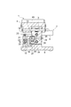
- FIG. 4 is a partially enlarged side view (including a partial cross section) of the optical fiber cutter shown in FIG. 3.
- FIG. 4 is a partially enlarged rear view (including a partial cross section) of the optical fiber cutter shown in FIG. 3.
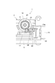
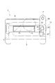
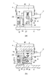
- FIG. 4 is a side view showing a state where a part of the optical fiber cutter shown in FIG. 3 is removed. It is sectional drawing seen from the rear view and back direction of an optical fiber cutter at the time of setting the rotation operation mode of a round blade member to non-rotation mode.
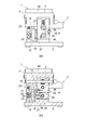
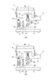
- FIG. 9 is a side view and a cross-sectional view of the optical fiber cutter as viewed from the side when the slider is moved rearward from the state shown in FIG. 8. It is sectional drawing seen from the back view and back direction of an optical fiber cutter at the time of setting the rotation operation mode of a round blade member to a continuous rotation mode. It is sectional drawing seen from the side view and side surface direction of an optical fiber cutter at the time of setting the rotation operation mode of a round blade member to a continuous rotation mode.
- FIG. 12 is a side view of the optical fiber cutter when the slider is moved to the rear side from the state shown in FIG.
- FIG. 14 is a rear view of the optical fiber cutter when the slider is moved rearward from the state illustrated in FIG. 13. It is a rear view which shows the example which attached the knob to the side surface by the side of the operation lever pin of a pin member.
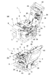
- FIGS. 1 and 2 are perspective views showing an embodiment of an optical fiber cutter according to the present invention.
- FIG. 3 is a side view and a rear view of the optical fiber cutter shown in FIGS. 1 and 2.
- the optical fiber cutter 1 of this embodiment is an apparatus which cut
- the optical fiber cutter 1 includes a cutter body 2 having a substantially I-shaped cross section, and a lid 4 connected to the cutter body 2 through a support shaft 3 so as to be opened and closed.
- the cutter main body 2 includes a base 5, a mounting table 6 disposed above the base 5, and a connecting portion 7 that connects the base 5 and the mounting table 6.
- a substantially rectangular concave holder guide portion 9 for positioning a fiber holder 8 that holds an optical fiber to be cut is formed on the upper surface of the mounting table 6, a substantially rectangular concave holder guide portion 9 for positioning a fiber holder 8 that holds an optical fiber to be cut is formed.
- An exposure hole 6 a extending in the front-rear direction of the cutter body 2 (in a direction orthogonal to the axial direction of the optical fiber placed on the mounting table 6) is formed in a portion of the mounting table 6 adjacent to the holder guide portion 9. .
- a pair of lower clamps 10 with rubber are fixed so as to sandwich the exposure holes 6a.
- a magnet receiver 11 is provided at the front end of the upper surface of the mounting table 6 (the end opposite to the support shaft 3).
- a slider 12 is attached to the cutter body 2 so as to be movable in the front-rear direction.
- the slider 12 is disposed in a space between the base 5 and the mounting table 6.
- a guide rail 13 having a U-shaped cross section extending in the front-rear direction is attached to one side surface of the connecting portion 7 (see FIG. 6).
- a guide block 15 slidably supported on the guide rail 13 via a ball slide (not shown) is attached to the back surface of the slider 12 (see FIG. 6).
- a contact portion 16 made of rubber rubber, resin material, or the like is mounted on the rear end side of the back surface of the slider 12.
- a round blade mounting member 17 is fixed to the front surface of the slider 12 with two screws.
- a disc-shaped round blade member 19 that scratches the optical fiber is rotatably attached to the round blade attachment member 17.
- the round blade member 19 is attached to the round blade attachment member 17 so as to slightly protrude upward from the exposure hole 6a.
- a circular gear 20 is attached to the round blade member 19, and the round blade member 19 and the circular gear 20 can rotate integrally.
- a protrusion 21 is disposed adjacent to the round blade member 19 on the slider 12.
- a substantially U-shaped protrusion 22 is erected on the rear end of the base 5 on the slider 12 side, and an arm-like member 23 extending forward is fixed to the protrusion 22.
- the arm-like member 23 supports a tooth receiving portion 24 that engages with the teeth of the circular gear 20 so as to be rotatable about a shaft 23a.
- a coil spring 25 that is urged upward (toward the tooth receiving portion 24) is disposed.
- the circular gear 20, the protrusion 22, the arm-like member 23, the tooth receiving portion 24, and the coil spring 25 constitute a round blade rotating unit that rotates the round blade member 19.
- a wall portion 26 which is a part of the cutter body 2 is provided at the center rear end portion of the base 5.
- the lid portion 4 is connected to the upper portion of the wall portion 26 via the support shaft portion 3 so as to be freely opened and closed.
- a stopper 27 that is engaged with the contact portion 16 of the slider 12 is fixed to the lower portion of the side surface of the wall portion 26 on the slider 12 side. The stopper 27 restricts the backward movement of the slider 12.
- a pin member 28 passes through the wall portion 26 at a position above the stopper 27.
- An operation lever pin 29 for switching the rotational operation mode of the round blade member 19 is attached to one end side of the pin member 28 (opposite side of the slider 12).
- the rotation operation mode of the round blade member 19 includes a non-rotation mode (first mode) in which the rotation of the round blade member 19 is limited so as not to rotate the round blade member 19 and a round blade every time the slider 12 moves backward.
- a normal rotation mode (second mode) in which the member 19 is rotated by a predetermined angle (for example, 15 degrees), and when the slider 12 is moved backward, the circular blade member 19 is rotated by a predetermined angle only once and then automatically. Therefore, there are three modes, ie, a one-time rotation mode (third mode) in which the circular blade member 19 is not rotated by switching to the non-rotation mode (forcefully).
- Such a rotation operation mode can be switched by moving the operation lever pin 29 in the vertical direction while rotating the pin member 28.
- a notch 30 for holding the operation lever pin 29 at a position corresponding to the non-rotation mode is formed at the end of the wall 26 opposite to the slider 12 side.
- a notch 31 is formed above the notch 30 in the wall 26 to hold the operation lever pin 29 at a position corresponding to the normal rotation mode.
- An operation lever pin is located below the notch 30 in the wall 26.
- a notch 32 is formed to hold 29 at a position corresponding to the single rotation mode.
- a stopper 33 is provided at the other end of the pin member 28 (end on the slider 12 side).
- the stopper 33 restricts the backward movement of the slider 12 at a position where the tooth receiving portion 24 does not hit the circular gear 20. That is, the stopper 33 restricts the backward movement of the slider 12 so as not to rotate the round blade member 19.
- a coil spring 34 that biases the stopper 33 is disposed inside the wall portion 26. Therefore, at normal times, the operation lever pin 29 enters the notch 30 by the urging force of the coil spring 34, so that the rotation operation mode is set to the non-rotation mode. In this state, the stopper 33 protrudes from the wall portion 26 to the slider 12 side.
- the rotation release pin 35 is attached to the stopper 33 so as to extend downward. As shown in FIG. 6, the rotation release pin 35 moves in conjunction with the operation lever pin 29 by the rotation of the pin member 28. In the state where the operation lever pin 29 enters the notch 30 and is held at the position corresponding to the non-rotation mode, the rotation release pin 35 extends obliquely forward and downward (see FIG. 8). In a state where the operation lever pin 29 is hooked on the notch 31 and is held at a position corresponding to the rotation mode at all times, the rotation release pin 35 extends downward (vertical direction) (see FIG. 11).
- the rotation release pin 35 is more than the state where the operation lever pin 29 is held at the position corresponding to the non-rotation mode. It extends forward (see FIG. 14).
- the wall 26, the pin member 28, the operation lever pin 29, the notches 30 to 32, the stopper 33, the coil spring 34 and the rotation release pin 35 are the first mode for preventing the round blade member 19 from rotating.
- a second mode for rotating the round blade member 19 by a predetermined angle by the round blade rotating means each time the slider 12 moves in one direction with respect to the cutter body 2, and the slider 12 being the cutter body.
- a rotational operation mode setting means for setting any one of the rotational operation modes is configured.
- a pillow portion 36 with rubber for bending the optical fiber damaged by the round blade member 19 and cutting the optical fiber.
- the pillow portion 36 is urged toward the back side (the cutter body 2 side) of the lid portion 4 by a coil spring (not shown).
- An engaging piece 37 that engages with the protrusion 21 when the lid 4 is closed with respect to the cutter body 2 is attached to the pillow 36.
- a pair of upper clamps 38 with rubber is fixed to the back surface of the lid 4 so as to sandwich the pillow 36.
- Each upper clamp 38 clamps the optical fiber placed on the mounting table 6 in cooperation with each lower clamp 10 described above.
- a magnet 39 and a handle 40 that are attracted to the magnet receiver 11 are attached to the front end (front end) of the back surface of the lid 4.
- the optical fiber is first held in the fiber holder 8 and then the slider 12 is positioned at the foremost position relative to the cutter body 2 (initial position). ), The fiber holder 8 is set on the holder guide portion 9 provided on the mounting table 6 of the cutter body 2 with the lid portion 4 opened.
- the lid 4 is closed. Then, the optical fiber is sandwiched between the clamps 10 and 38. Further, the engagement piece 37 attached to the lid portion 4 comes into contact with the protrusion 21 of the slider 12 so that the pillow portion 36 is held against the urging force of a spring (not shown).
- the slider 12 is moved backward with respect to the cutter body 2. Then, when the round blade member 19 comes into contact with the optical fiber, the optical fiber is damaged.
- the projection 21 passes through the engagement piece 37, so that the pillow portion 36 is lowered by the urging force of a spring (not shown), hits the optical fiber, and is bent into the optical fiber. Is granted.
- tension is applied to the optical fiber. As a result, the optical fiber breaks starting from a scratch attached to the optical fiber.
- the round blade member 19 is moved at a position shifted by a predetermined angle from the previous time.
- the optical fiber will be damaged.
- the stopper 33 is maintained in a state of being retracted into the wall portion 26, when the slider 12 is moved backward, the round blade member 19 rotates again in the same direction by a predetermined angle.
- the round blade member 19 is moved at a position shifted by a predetermined angle from the previous time.
- the optical fiber will be damaged.
- the rotation operation mode is switched to the non-rotation mode, when the slider 12 is further moved rearward, the contact portion 16 hits the stopper 33 and the round blade member 19 does not rotate.
- the circular blade member 19 is rotated after the optical fiber is cut by setting the rotation operation mode to the non-rotation mode by the operation lever pin 29. Do not let it.
- the rotary lever 29 is set to the normal rotation mode or the single rotation mode by the operation lever pin 29, so that the round blade member 19 is set at a predetermined angle after the optical fiber is cut. Just rotate it.
- the slider 12 when the rotation operation mode is set to the normal rotation mode or the single rotation mode by the operation lever pin 29, the slider 12 is simply moved rearward with respect to the cutter body 2. Since the tooth receiving portion 24 hits the circular gear 20 and the round blade member 19 rotates by a predetermined angle, it is not necessary for the operator to loosen the fixing of the round blade member 19 and rotate the round blade member 19. Thereby, the round blade member 19 can be rotated without putting an extra burden on an operator, and the workability of maintenance is also improved.
- the round blade member 19 is rotated by a predetermined angle only once, and thereafter the rotation operation is performed. Since the mode automatically switches to the non-rotating mode and the round blade member 19 does not rotate, for example, the round blade member 19 is rotated even though the cutting condition of the round blade member 19 is not reduced. Is prevented. As a result, the round blade member 19 can be used uniformly over the entire circumference without waste until the cutting condition of all positions of the round blade member 19 becomes poor. As a result, the life of the round blade member 19 can be made sufficiently long, and the management of the round blade member 19 can be easily performed.
- the present invention is not limited to the above embodiment.
- the rotation operation mode is performed by the operation lever pin 29.
- the operation lever may be provided with a knob 48 on the side surface of the pin member 28 on the operation lever pin 29 side so that the rotation operation mode can be easily set. In this case, the rotational operation mode can be set more easily than when the operation lever pin 29 is set.
Landscapes
- Physics & Mathematics (AREA)
- General Physics & Mathematics (AREA)
- Optics & Photonics (AREA)
- Life Sciences & Earth Sciences (AREA)
- Forests & Forestry (AREA)
- Engineering & Computer Science (AREA)
- Mechanical Engineering (AREA)
- Light Guides In General And Applications Therefor (AREA)
- Nonmetal Cutting Devices (AREA)
- Knives (AREA)
- Perforating, Stamping-Out Or Severing By Means Other Than Cutting (AREA)
Abstract
Priority Applications (7)
| Application Number | Priority Date | Filing Date | Title |
|---|---|---|---|
| EP12757440.8A EP2687881B1 (fr) | 2011-03-17 | 2012-03-15 | Outil de coupe de fibre optique |
| MYPI2013003348A MY181807A (en) | 2011-03-17 | 2012-03-15 | Optical fiber cutter |
| CN201280013805.9A CN103443672B (zh) | 2011-03-17 | 2012-03-15 | 光纤切割器 |
| US14/004,949 US9395492B2 (en) | 2011-03-17 | 2012-03-15 | Optical fiber cutter |
| SG2013065255A SG192995A1 (en) | 2011-03-17 | 2012-03-15 | Optical fiber cutter |
| CA2829749A CA2829749C (fr) | 2011-03-17 | 2012-03-15 | Outil de coupe de fibre optique |
| KR1020137027258A KR101909765B1 (ko) | 2011-03-17 | 2012-03-15 | 광섬유 커터 |
Applications Claiming Priority (2)
| Application Number | Priority Date | Filing Date | Title |
|---|---|---|---|
| JP2011-059593 | 2011-03-17 | ||
| JP2011059593A JP5217011B2 (ja) | 2011-03-17 | 2011-03-17 | 光ファイバカッタ |
Publications (1)
| Publication Number | Publication Date |
|---|---|
| WO2012124778A1 true WO2012124778A1 (fr) | 2012-09-20 |
Family
ID=46830842
Family Applications (1)
| Application Number | Title | Priority Date | Filing Date |
|---|---|---|---|
| PCT/JP2012/056758 WO2012124778A1 (fr) | 2011-03-17 | 2012-03-15 | Outil de coupe de fibre optique |
Country Status (9)
| Country | Link |
|---|---|
| US (1) | US9395492B2 (fr) |
| EP (1) | EP2687881B1 (fr) |
| JP (1) | JP5217011B2 (fr) |
| KR (1) | KR101909765B1 (fr) |
| CN (1) | CN103443672B (fr) |
| CA (1) | CA2829749C (fr) |
| MY (1) | MY181807A (fr) |
| SG (1) | SG192995A1 (fr) |
| WO (1) | WO2012124778A1 (fr) |
Families Citing this family (16)
| Publication number | Priority date | Publication date | Assignee | Title |
|---|---|---|---|---|
| JP5200064B2 (ja) * | 2010-06-28 | 2013-05-15 | 住友電気工業株式会社 | 光ファイバカッタ |
| US9726823B2 (en) * | 2012-02-20 | 2017-08-08 | Inno Instrument (China) Inc. | Optical fiber cutting knife |
| KR101915590B1 (ko) * | 2012-10-18 | 2018-11-06 | 이노 인스트루먼트 (차이나). 인코퍼레이션 | 전자동 광섬유 절단기 |
| DE102015204417A1 (de) * | 2015-03-12 | 2016-09-15 | Audi Ag | Schneideinheit mit einer Klinge zum Trennen zumindest einer Faser, insbesondere zur Herstellung von Faservorformlingen |
| JP6611008B2 (ja) * | 2016-02-29 | 2019-11-27 | Seiオプティフロンティア株式会社 | 光ファイバカッタ |
| JP1563774S (fr) * | 2016-05-27 | 2016-11-21 | ||
| JP6190029B1 (ja) * | 2016-11-02 | 2017-08-30 | 株式会社フジクラ | 光ファイバ切断システム |
| JP6244491B1 (ja) * | 2017-03-06 | 2017-12-06 | 株式会社フジクラ | 光ファイバ切断装置 |
| EP3401715B1 (fr) * | 2017-03-24 | 2020-04-29 | Fujikura Ltd. | Dispositif de découpe de fibre optique |
| US11065778B2 (en) | 2017-03-24 | 2021-07-20 | Fujikura Ltd. | Optical fiber cutter |
| US10591673B2 (en) * | 2017-04-04 | 2020-03-17 | Fujikura Ltd. | Optical fiber cutting system |
| CN107479131A (zh) * | 2017-08-22 | 2017-12-15 | 四川灼识科技股份有限公司 | 一种光纤旋转切割方法 |
| US10994435B2 (en) * | 2017-10-11 | 2021-05-04 | D-Cut Products, Inc. | Score cutting tool |
| JP6273399B1 (ja) * | 2017-11-20 | 2018-01-31 | 株式会社フジクラ | 光ファイバ切断装置 |
| JP6785211B2 (ja) * | 2017-11-30 | 2020-11-18 | 株式会社フジクラ | 光ファイバ切断システム |
| KR20190001981U (ko) | 2018-01-27 | 2019-08-06 | 주식회사 레이컴즈 | 광섬유 절단기 교환용 칼날 보호구 |
Citations (2)
| Publication number | Priority date | Publication date | Assignee | Title |
|---|---|---|---|---|
| JP2001296430A (ja) | 2000-04-11 | 2001-10-26 | Sumiden Asahi Industries Ltd | 光ファイバカッタ |
| JP2008203815A (ja) * | 2007-01-23 | 2008-09-04 | Sumitomo Electric Ind Ltd | 光ファイバ切断装置 |
Family Cites Families (11)
| Publication number | Priority date | Publication date | Assignee | Title |
|---|---|---|---|---|
| CH657304A5 (de) * | 1980-09-16 | 1986-08-29 | Gottlieb Looser | Vorrichtung zum auftrennen von bahnen oder schlaeuchen aus kunststoffolie. |
| IT1283800B1 (it) * | 1995-09-01 | 1998-04-30 | Burr Oak Tool & Gauge | Dispositivo di taglio stazionario e spostabile in modo graduato |
| US5761976A (en) * | 1997-04-15 | 1998-06-09 | Automatic Handling, Inc. | Knife Assembly |
| US6807886B1 (en) * | 1998-01-05 | 2004-10-26 | Productive Solutions Inc | Knife indexing apparatus |
| CN100396411C (zh) | 2002-08-26 | 2008-06-25 | 日新精密工业株式会社 | 光纤自动切断器 |
| KR100471083B1 (ko) * | 2002-12-24 | 2005-03-10 | 삼성전자주식회사 | 광섬유 절단장치 |
| JP2006251034A (ja) * | 2005-03-08 | 2006-09-21 | Fujikura Ltd | 光ファイバ切断装置 |
| KR20080037498A (ko) * | 2006-10-26 | 2008-04-30 | 일신테크(주) | 광섬유 절단기 |
| CA2618617C (fr) * | 2007-01-23 | 2016-03-29 | Sumitomo Electric Industries, Ltd. | Dispositif de coupe pour fibre optique |
| JP5084464B2 (ja) | 2007-05-23 | 2012-11-28 | 住友電気工業株式会社 | 光ファイバの切断装置及び光ファイバの切断方法 |
| JP5084466B2 (ja) * | 2007-11-21 | 2012-11-28 | 住友電気工業株式会社 | 光ファイバ切断用カッター、光ファイバの切断方法および光ファイバ切断用カッターを備えた光ファイバ切断機 |
-
2011
- 2011-03-17 JP JP2011059593A patent/JP5217011B2/ja active Active
-
2012
- 2012-03-15 US US14/004,949 patent/US9395492B2/en active Active
- 2012-03-15 CA CA2829749A patent/CA2829749C/fr active Active
- 2012-03-15 SG SG2013065255A patent/SG192995A1/en unknown
- 2012-03-15 CN CN201280013805.9A patent/CN103443672B/zh active Active
- 2012-03-15 WO PCT/JP2012/056758 patent/WO2012124778A1/fr active Application Filing
- 2012-03-15 EP EP12757440.8A patent/EP2687881B1/fr active Active
- 2012-03-15 KR KR1020137027258A patent/KR101909765B1/ko active IP Right Grant
- 2012-03-15 MY MYPI2013003348A patent/MY181807A/en unknown
Patent Citations (2)
| Publication number | Priority date | Publication date | Assignee | Title |
|---|---|---|---|---|
| JP2001296430A (ja) | 2000-04-11 | 2001-10-26 | Sumiden Asahi Industries Ltd | 光ファイバカッタ |
| JP2008203815A (ja) * | 2007-01-23 | 2008-09-04 | Sumitomo Electric Ind Ltd | 光ファイバ切断装置 |
Non-Patent Citations (1)
| Title |
|---|
| See also references of EP2687881A4 |
Also Published As
| Publication number | Publication date |
|---|---|
| US9395492B2 (en) | 2016-07-19 |
| EP2687881A1 (fr) | 2014-01-22 |
| SG192995A1 (en) | 2013-10-30 |
| CN103443672B (zh) | 2016-03-23 |
| CA2829749C (fr) | 2018-06-12 |
| KR20140016942A (ko) | 2014-02-10 |
| US20140000434A1 (en) | 2014-01-02 |
| EP2687881B1 (fr) | 2017-04-19 |
| JP5217011B2 (ja) | 2013-06-19 |
| KR101909765B1 (ko) | 2018-10-18 |
| EP2687881A4 (fr) | 2014-08-20 |
| MY181807A (en) | 2021-01-07 |
| CN103443672A (zh) | 2013-12-11 |
| CA2829749A1 (fr) | 2012-09-20 |
| JP2012194465A (ja) | 2012-10-11 |
Similar Documents
| Publication | Publication Date | Title |
|---|---|---|
| WO2012124778A1 (fr) | Outil de coupe de fibre optique | |
| JP5200064B2 (ja) | 光ファイバカッタ | |
| US9229166B2 (en) | Optical fiber cutter, and optical fiber cutter unit | |
| JP2013022702A (ja) | 電動工具 | |
| EP2145711A2 (fr) | Dispositifs de découpe | |
| JP2008142889A (ja) | 電動手工具装置 | |
| TW201041679A (en) | Miter saw with work surface extensions | |
| JP2008023796A (ja) | 切断機のバイス機構 | |
| JP2010158755A (ja) | 電動工具のスイッチ | |
| JP5989552B2 (ja) | 卓上切断機 | |
| JP4847084B2 (ja) | 切断機 | |
| EP2436494B1 (fr) | Découpeuse avec un ensemble de protection | |
| JP2000326303A (ja) | 刃板着脱構造 | |
| JP2012116048A (ja) | 携帯用切断機 | |
| US6725790B2 (en) | Cloth cutting knife driving device | |
| WO2015005087A1 (fr) | Outil de coupe | |
| JP2009066718A (ja) | 卓上丸鋸盤における回転テーブルの位置決め装置 | |
| JP2006044066A (ja) | フリップオーバーソー | |
| JP5315968B2 (ja) | 携帯用切断機 | |
| JP2010076059A (ja) | 携帯用切断機 | |
| JP2002286944A (ja) | ハンディ型光ファイバカッタ | |
| JP2015071228A (ja) | 切断工具 | |
| JP2003236801A (ja) | 切断機の調整式加工材料サポートバー | |
| JP2006321011A (ja) | 紙裁断機用スライダー及び紙裁断機 |
Legal Events
| Date | Code | Title | Description |
|---|---|---|---|
| WWE | Wipo information: entry into national phase |
Ref document number: 201280013805.9 Country of ref document: CN |
|
| 121 | Ep: the epo has been informed by wipo that ep was designated in this application |
Ref document number: 12757440 Country of ref document: EP Kind code of ref document: A1 |
|
| ENP | Entry into the national phase |
Ref document number: 2829749 Country of ref document: CA |
|
| WWE | Wipo information: entry into national phase |
Ref document number: 14004949 Country of ref document: US |
|
| NENP | Non-entry into the national phase |
Ref country code: DE |
|
| WWE | Wipo information: entry into national phase |
Ref document number: 1301005191 Country of ref document: TH |
|
| REEP | Request for entry into the european phase |
Ref document number: 2012757440 Country of ref document: EP |
|
| WWE | Wipo information: entry into national phase |
Ref document number: 2012757440 Country of ref document: EP |
|
| ENP | Entry into the national phase |
Ref document number: 20137027258 Country of ref document: KR Kind code of ref document: A |