WO2012124188A1 - 非水二次電池用電極、その製造方法、および非水二次電池 - Google Patents
非水二次電池用電極、その製造方法、および非水二次電池 Download PDFInfo
- Publication number
- WO2012124188A1 WO2012124188A1 PCT/JP2011/070689 JP2011070689W WO2012124188A1 WO 2012124188 A1 WO2012124188 A1 WO 2012124188A1 JP 2011070689 W JP2011070689 W JP 2011070689W WO 2012124188 A1 WO2012124188 A1 WO 2012124188A1
- Authority
- WO
- WIPO (PCT)
- Prior art keywords
- electrode
- current collector
- mixture layer
- electrode mixture
- secondary battery
- Prior art date
- Legal status (The legal status is an assumption and is not a legal conclusion. Google has not performed a legal analysis and makes no representation as to the accuracy of the status listed.)
- Ceased
Links
Images






Classifications
-
- H—ELECTRICITY
- H01—ELECTRIC ELEMENTS
- H01M—PROCESSES OR MEANS, e.g. BATTERIES, FOR THE DIRECT CONVERSION OF CHEMICAL ENERGY INTO ELECTRICAL ENERGY
- H01M50/00—Constructional details or processes of manufacture of the non-active parts of electrochemical cells other than fuel cells, e.g. hybrid cells
- H01M50/10—Primary casings; Jackets or wrappings
- H01M50/147—Lids or covers
- H01M50/166—Lids or covers characterised by the methods of assembling casings with lids
- H01M50/171—Lids or covers characterised by the methods of assembling casings with lids using adhesives or sealing agents
-
- H—ELECTRICITY
- H01—ELECTRIC ELEMENTS
- H01M—PROCESSES OR MEANS, e.g. BATTERIES, FOR THE DIRECT CONVERSION OF CHEMICAL ENERGY INTO ELECTRICAL ENERGY
- H01M10/00—Secondary cells; Manufacture thereof
- H01M10/05—Accumulators with non-aqueous electrolyte
- H01M10/052—Li-accumulators
-
- H—ELECTRICITY
- H01—ELECTRIC ELEMENTS
- H01M—PROCESSES OR MEANS, e.g. BATTERIES, FOR THE DIRECT CONVERSION OF CHEMICAL ENERGY INTO ELECTRICAL ENERGY
- H01M10/00—Secondary cells; Manufacture thereof
- H01M10/05—Accumulators with non-aqueous electrolyte
- H01M10/056—Accumulators with non-aqueous electrolyte characterised by the materials used as electrolytes, e.g. mixed inorganic/organic electrolytes
- H01M10/0564—Accumulators with non-aqueous electrolyte characterised by the materials used as electrolytes, e.g. mixed inorganic/organic electrolytes the electrolyte being constituted of organic materials only
- H01M10/0566—Liquid materials
-
- H—ELECTRICITY
- H01—ELECTRIC ELEMENTS
- H01M—PROCESSES OR MEANS, e.g. BATTERIES, FOR THE DIRECT CONVERSION OF CHEMICAL ENERGY INTO ELECTRICAL ENERGY
- H01M10/00—Secondary cells; Manufacture thereof
- H01M10/05—Accumulators with non-aqueous electrolyte
- H01M10/058—Construction or manufacture
- H01M10/0587—Construction or manufacture of accumulators having only wound construction elements, i.e. wound positive electrodes, wound negative electrodes and wound separators
-
- H—ELECTRICITY
- H01—ELECTRIC ELEMENTS
- H01M—PROCESSES OR MEANS, e.g. BATTERIES, FOR THE DIRECT CONVERSION OF CHEMICAL ENERGY INTO ELECTRICAL ENERGY
- H01M4/00—Electrodes
- H01M4/02—Electrodes composed of, or comprising, active material
- H01M4/13—Electrodes for accumulators with non-aqueous electrolyte, e.g. for lithium-accumulators; Processes of manufacture thereof
- H01M4/131—Electrodes based on mixed oxides or hydroxides, or on mixtures of oxides or hydroxides, e.g. LiCoOx
-
- H—ELECTRICITY
- H01—ELECTRIC ELEMENTS
- H01M—PROCESSES OR MEANS, e.g. BATTERIES, FOR THE DIRECT CONVERSION OF CHEMICAL ENERGY INTO ELECTRICAL ENERGY
- H01M4/00—Electrodes
- H01M4/02—Electrodes composed of, or comprising, active material
- H01M4/13—Electrodes for accumulators with non-aqueous electrolyte, e.g. for lithium-accumulators; Processes of manufacture thereof
- H01M4/139—Processes of manufacture
- H01M4/1391—Processes of manufacture of electrodes based on mixed oxides or hydroxides, or on mixtures of oxides or hydroxides, e.g. LiCoOx
-
- H—ELECTRICITY
- H01—ELECTRIC ELEMENTS
- H01M—PROCESSES OR MEANS, e.g. BATTERIES, FOR THE DIRECT CONVERSION OF CHEMICAL ENERGY INTO ELECTRICAL ENERGY
- H01M4/00—Electrodes
- H01M4/02—Electrodes composed of, or comprising, active material
- H01M4/36—Selection of substances as active materials, active masses, active liquids
- H01M4/48—Selection of substances as active materials, active masses, active liquids of inorganic oxides or hydroxides
- H01M4/485—Selection of substances as active materials, active masses, active liquids of inorganic oxides or hydroxides of mixed oxides or hydroxides for inserting or intercalating light metals, e.g. LiTi2O4 or LiTi2OxFy
-
- H—ELECTRICITY
- H01—ELECTRIC ELEMENTS
- H01M—PROCESSES OR MEANS, e.g. BATTERIES, FOR THE DIRECT CONVERSION OF CHEMICAL ENERGY INTO ELECTRICAL ENERGY
- H01M4/00—Electrodes
- H01M4/02—Electrodes composed of, or comprising, active material
- H01M4/36—Selection of substances as active materials, active masses, active liquids
- H01M4/48—Selection of substances as active materials, active masses, active liquids of inorganic oxides or hydroxides
- H01M4/50—Selection of substances as active materials, active masses, active liquids of inorganic oxides or hydroxides of manganese
- H01M4/505—Selection of substances as active materials, active masses, active liquids of inorganic oxides or hydroxides of manganese of mixed oxides or hydroxides containing manganese for inserting or intercalating light metals, e.g. LiMn2O4 or LiMn2OxFy
-
- H—ELECTRICITY
- H01—ELECTRIC ELEMENTS
- H01M—PROCESSES OR MEANS, e.g. BATTERIES, FOR THE DIRECT CONVERSION OF CHEMICAL ENERGY INTO ELECTRICAL ENERGY
- H01M4/00—Electrodes
- H01M4/02—Electrodes composed of, or comprising, active material
- H01M4/36—Selection of substances as active materials, active masses, active liquids
- H01M4/48—Selection of substances as active materials, active masses, active liquids of inorganic oxides or hydroxides
- H01M4/52—Selection of substances as active materials, active masses, active liquids of inorganic oxides or hydroxides of nickel, cobalt or iron
- H01M4/525—Selection of substances as active materials, active masses, active liquids of inorganic oxides or hydroxides of nickel, cobalt or iron of mixed oxides or hydroxides containing iron, cobalt or nickel for inserting or intercalating light metals, e.g. LiNiO2, LiCoO2 or LiCoOxFy
-
- H—ELECTRICITY
- H01—ELECTRIC ELEMENTS
- H01M—PROCESSES OR MEANS, e.g. BATTERIES, FOR THE DIRECT CONVERSION OF CHEMICAL ENERGY INTO ELECTRICAL ENERGY
- H01M50/00—Constructional details or processes of manufacture of the non-active parts of electrochemical cells other than fuel cells, e.g. hybrid cells
- H01M50/50—Current conducting connections for cells or batteries
- H01M50/531—Electrode connections inside a battery casing
- H01M50/54—Connection of several leads or tabs of plate-like electrode stacks, e.g. electrode pole straps or bridges
-
- H—ELECTRICITY
- H01—ELECTRIC ELEMENTS
- H01M—PROCESSES OR MEANS, e.g. BATTERIES, FOR THE DIRECT CONVERSION OF CHEMICAL ENERGY INTO ELECTRICAL ENERGY
- H01M50/00—Constructional details or processes of manufacture of the non-active parts of electrochemical cells other than fuel cells, e.g. hybrid cells
- H01M50/50—Current conducting connections for cells or batteries
- H01M50/543—Terminals
- H01M50/552—Terminals characterised by their shape
- H01M50/559—Terminals adapted for cells having curved cross-section, e.g. round, elliptic or button cells
- H01M50/56—Cup shaped terminals
-
- H—ELECTRICITY
- H01—ELECTRIC ELEMENTS
- H01M—PROCESSES OR MEANS, e.g. BATTERIES, FOR THE DIRECT CONVERSION OF CHEMICAL ENERGY INTO ELECTRICAL ENERGY
- H01M50/00—Constructional details or processes of manufacture of the non-active parts of electrochemical cells other than fuel cells, e.g. hybrid cells
- H01M50/10—Primary casings; Jackets or wrappings
- H01M50/147—Lids or covers
- H01M50/166—Lids or covers characterised by the methods of assembling casings with lids
- H01M50/167—Lids or covers characterised by the methods of assembling casings with lids by crimping
-
- Y—GENERAL TAGGING OF NEW TECHNOLOGICAL DEVELOPMENTS; GENERAL TAGGING OF CROSS-SECTIONAL TECHNOLOGIES SPANNING OVER SEVERAL SECTIONS OF THE IPC; TECHNICAL SUBJECTS COVERED BY FORMER USPC CROSS-REFERENCE ART COLLECTIONS [XRACs] AND DIGESTS
- Y02—TECHNOLOGIES OR APPLICATIONS FOR MITIGATION OR ADAPTATION AGAINST CLIMATE CHANGE
- Y02E—REDUCTION OF GREENHOUSE GAS [GHG] EMISSIONS, RELATED TO ENERGY GENERATION, TRANSMISSION OR DISTRIBUTION
- Y02E60/00—Enabling technologies; Technologies with a potential or indirect contribution to GHG emissions mitigation
- Y02E60/10—Energy storage using batteries
-
- Y—GENERAL TAGGING OF NEW TECHNOLOGICAL DEVELOPMENTS; GENERAL TAGGING OF CROSS-SECTIONAL TECHNOLOGIES SPANNING OVER SEVERAL SECTIONS OF THE IPC; TECHNICAL SUBJECTS COVERED BY FORMER USPC CROSS-REFERENCE ART COLLECTIONS [XRACs] AND DIGESTS
- Y02—TECHNOLOGIES OR APPLICATIONS FOR MITIGATION OR ADAPTATION AGAINST CLIMATE CHANGE
- Y02P—CLIMATE CHANGE MITIGATION TECHNOLOGIES IN THE PRODUCTION OR PROCESSING OF GOODS
- Y02P70/00—Climate change mitigation technologies in the production process for final industrial or consumer products
- Y02P70/50—Manufacturing or production processes characterised by the final manufactured product
Definitions
- the present invention includes a stacked electrode group, an electrode capable of constituting a non-aqueous secondary battery having a high capacity and good productivity, a method for manufacturing the same, and a non-contact including a stacked electrode group having the electrode.
- the present invention relates to a water secondary battery.
- a positive electrode mixture layer or a negative electrode mixture layer is formed on one or both sides of a current collector on a positive electrode and a negative electrode, and a part of the current collector is a positive electrode mixture layer. And exposed without forming a negative electrode mixture layer, and using this as a current collecting tab, the current collecting tabs of each positive electrode and each negative electrode are welded together, and the collected current collecting tabs are connected to terminals.
- a positive electrode mixture layer or a negative electrode mixture layer is formed on one or both sides of a current collector on a positive electrode and a negative electrode, and a part of the current collector is a positive electrode mixture layer.
- the current collecting tabs of each positive electrode and each negative electrode are welded together, and the collected current collecting tabs are connected to terminals.
- Patent Document 1 There are some which are used for electrical connection with the inner surface of an exterior case or a sealing case that also serves as a material.
- the electrode of the non-aqueous secondary battery has an electrode mixture layer forming composition prepared by dispersing an electrode active material (positive electrode active material or negative electrode active material) in a solvent on one or both sides of the current collector.
- an electrode active material positive electrode active material or negative electrode active material
- it is manufactured through a process of forming an electrode mixture layer (a positive electrode mixture layer or a negative electrode mixture layer) by coating and drying (for example, Patent Document 2).
- Patent Document 3 a proposal for a method for producing an electrode for a non-aqueous secondary battery using a screen printing method.
- an electrode body having a winding structure in which a positive electrode and a negative electrode are stacked with a separator interposed therebetween and wound in a spiral shape is often used.
- a reduction in thickness in the vicinity of the boundary portion between the electrode mixture layer and the exposed portion of the current collector greatly affects the capacity.
- the electrode mixture layer related to the electrode used in the battery has a central portion and an end portion in plan view. Development of technology to reduce the variation in thickness is required.
- the present invention has been made in view of the above circumstances, and an object of the present invention is to provide a non-aqueous secondary battery having a high capacity and good productivity, which includes a stacked electrode group, and its manufacture
- the present invention provides a method and a non-aqueous secondary battery including a stacked electrode group having the electrodes.
- the electrode for a non-aqueous secondary battery of the present invention that can achieve the above object is used for a non-aqueous secondary battery having an electrode group in which a plurality of electrodes are stacked substantially in parallel (including parallel) via a separator.
- a mixture layer is formed, and in the current collector tab portion, an electrode mixture layer is not formed on the current collector and the current collector is exposed, and the current collector of the electrode mixture layer
- the angle between the side surface at the boundary portion with the exposed portion and the surface in contact with the current collector in the electrode mixture layer is 45 ° or more and less than 90 °.
- the electrode for a non-aqueous secondary battery of the present invention has a mold for forming an electrode mixture layer on the surface of a current collector, and the electrode mixture layer forming composition containing an electrode active material and a solvent is used as the mold.
- the mold has a step of removing the mold after drying, and the mold has a side surface whose opening area on the current collector side is larger than the opening area on the opposite side of the current collector It can be manufactured by the method for manufacturing an electrode for a non-aqueous secondary battery of the present invention, which is so inclined.
- the positive electrodes and the negative electrodes are alternately stacked via separators and substantially parallel (including parallel), and the total number of positive electrodes and negative electrodes is three or more.
- the positive electrode has a current collecting tab portion protruding from the main body portion in plan view, and the main body portion includes a current collector.
- a positive electrode mixture layer containing a positive electrode active material is formed on one side or both sides, and in the current collector tab portion, the positive electrode mixture layer is not formed on the current collector, and the current collector is exposed,
- the negative electrode has a current collecting tab portion protruding from the main body portion in plan view, and the main body portion has a negative electrode agent layer containing a negative electrode active material formed on one side or both sides of the current collector.
- the current collector tab portion the current collector is exposed without a negative electrode layer formed on the current collector, and the positive electrode and / or Others the negative electrode is characterized in that a non-aqueous secondary battery electrode of the present invention.
- an electrode that includes a stacked electrode group and can constitute a non-aqueous secondary battery with high capacity and good productivity, a manufacturing method thereof, and a stacked electrode group having the electrode are provided.
- a non-aqueous secondary battery can be provided. That is, the nonaqueous secondary battery of the present invention has a high capacity and good productivity.
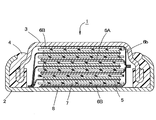
- FIG. 1 is a longitudinal sectional view schematically showing an example of the nonaqueous secondary battery of the present invention.
- a non-aqueous secondary battery 1 shown in FIG. 1 is a flat non-aqueous secondary battery, and a plurality of positive electrodes 5 and a plurality of negative electrodes 6 (6A, 6B) are connected to each other through a separator 7 so that the flat surface of the battery is flat.
- the sealing case 3 is fitted to the opening of the outer case 2 via an insulating gasket 4, and the opening end of the outer case 2 is tightened inward, whereby the insulating gasket 4 contacts the sealing case 3.
- the opening part of the exterior case 2 is sealed, and the inside of the battery has a sealed structure.
- the stacked surfaces of the positive electrode 5, the negative electrode 6, and the separator 7 are substantially parallel (including parallel) to the flat surfaces of the battery, that is, the flat surfaces of the outer case 2 and the sealing case 3.
- the outer case 2, the sealing case 3, and the insulating gasket 4 are housed in the outer case.
- the outer case 2 and the sealing case 3 are made of a metal such as stainless steel, and the insulating gasket 4 is made of an insulating resin such as nylon.
- the positive electrode 5 and the negative electrode 6 of the flat non-aqueous secondary battery 1 shown in FIG. 1 are both non-aqueous secondary battery electrodes of the present invention.
- FIG. 2 schematically shows a plan view of the positive electrode 5.
- the positive electrode 5 includes a main body portion 5a and a current collecting tab portion 5b protruding from the main body portion 5a in plan view.
- the current collecting tab portion 5b usually has a width (length in the vertical direction in FIG. 2) narrower than that of the main body portion 5a.
- the positive electrode mixture layer 51 is formed on both surfaces of the current collector 52.
- the positive electrode mixture layer 51 is not formed on the surface of the current collector 52, and the current collector 52 is exposed.
- the outermost electrodes (upper and lower ends in the figure) are all negative electrodes (negative electrode 6B), and all of the positive electrodes 5 are on both sides (both sides) via the separator 7. Since it faces the negative electrode 6, it has the positive electrode mixture layer 51 on both surfaces of the current collector 52.
- the outermost positive electrode of the electrode group is a positive electrode
- the outermost positive electrode May have a structure having a positive electrode mixture layer only on one side of the current collector (the surface inside the battery).
- FIG. 3 schematically shows a plan view of the negative electrode 6.
- the negative electrode 6 has a main body portion 6a and a current collecting tab portion 6b protruding from the main body portion 6a in plan view.
- the current collecting tab portion 6b usually has a width (length in the vertical direction in FIG. 3) narrower than that of the main body portion 6a.
- the main body portion 6 a of the negative electrode 6 ⁇ / b> B located at the outermost part of the electrode group has a negative electrode mixture layer 61 formed only on one surface (surface inside the battery) of the current collector 62.
- the negative electrode mixture layer 61 is formed on both surfaces of the current collector 62 in the main body portion 6a of the negative electrode 6A other than that. Further, in the current collecting tab portion 6b of the negative electrodes 6A and 6B, the negative electrode mixture layer 61 is not formed on the surface of the current collector 62, and the current collector is exposed.
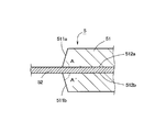
- FIG. 4 is an enlarged view schematically showing the main part of the longitudinal section of the positive electrode 5 shown in FIG.
- the positive electrode 5 according to the battery shown in FIG. 1 has side surfaces (511a and 511b in FIG. 4) at the boundary portion of the positive electrode mixture layer 51 with the exposed portion of the current collector 52.
- An angle (angles A and A ′ in FIG. 4) between the surfaces in contact with the current collector 52 in the positive electrode mixture layer 51 (512a and 512b in FIG. 4) is 45 ° or more and less than 90 °.
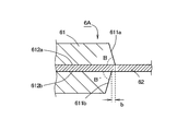
- FIG. 5 is an enlarged view schematically showing the main part of the longitudinal section of the negative electrode 6 shown in FIG.
- the negative electrode 6 according to the battery shown in FIG. 1 has side surfaces (611 a and 611 b in FIG. 5) at the boundary portion between the negative electrode mixture layer 61 and the exposed portion of the current collector 62.
- the angles (angles B and B ′ in FIG. 5) between the surfaces in contact with the current collector 62 in the positive electrode mixture layer 61 (612a and 612b in FIG. 5) are 45 ° or more and less than 90 °.
- the electrode for a non-aqueous secondary battery of the present invention has a main body part and a current collecting tab part protruding from the main body part in plan view.
- the electrode mixture layer containing the electrode active material (positive electrode mixture layer or negative electrode mixture layer) is formed on one side or both sides of the current collector, and the current collector tab portion has the electrode mixture layer on the current collector.
- the current collector is not formed and the angle between the side surface of the electrode mixture layer at the boundary with the exposed portion of the current collector and the surface in contact with the current collector in the electrode mixture layer Is 45 ° or more and less than 90 °.
- an electrode when an electrode is produced through a step of applying a composition for forming an electrode mixture layer prepared by dispersing a constituent material of an electrode mixture layer such as an electrode active material in a solvent to a current collector,
- a composition for forming an electrode mixture layer prepared by dispersing a constituent material of an electrode mixture layer such as an electrode active material in a solvent to a current collector
- the electrode mixture layer When the electrode mixture layer is not formed on a part of the electric conductor and is an exposed portion, the side surface of the electrode mixture layer at the boundary portion with the exposed portion of the current collector is gently inclined.
- the angles A and A ′ in FIG. 4 and the angles B and B ′ in FIG. 5 tend to be very small.
- the electrode mixture layer on the side surface portion at the boundary portion with the exposed portion of the current collector Therefore, the influence on the battery capacity due to the gentle inclination of the side surface is extremely small.
- each electrode has a boundary with the exposed portion of the current collector. Since the ratio of the side surface portion in the portion to the entire electrode mixture layer is relatively large, the battery capacity is reduced.
- an electrode mixture layer in the case where the electrode mixture layer is provided only on one side of the current collector, the electrode mixture layer is formed on both sides of the current collector. In the case of having a layer, both of these electrode mixture layers.
- the electrode mixture layer is the same unless otherwise specified)
- the angle between the surface in contact with the current collector is set to 45 ° or more, preferably 60 ° or more, so as to suppress a decrease in battery capacity due to the shape of the side surface as much as possible.
- the electrode for a non-aqueous secondary battery of the present invention has a mold placed on the surface of the current collector, filled with a composition for forming an electrode mixture layer in the holes of the mold, and dried.
- the angle between the side surface of the electrode mixture layer at the boundary portion with the exposed portion of the current collector and the surface in contact with the current collector in the electrode mixture layer is 90.
- the angle is less than 0 °, preferably not more than 86 °, it is possible to increase the production of the electrode particularly when manufacturing by the above method.
- the angle between the other part of the side surface of the electrode mixture layer and the surface in contact with the current collector of the electrode mixture layer may be 90 °, for example. Good.
- the angle between the entire side surface of the electrode mixture layer and the surface in contact with the current collector of the electrode mixture layer is as described above. More preferably, the value is 45 ° or more, preferably 60 ° or more and less than 90 °, preferably 86 ° or less.
- the positive electrode 5 according to the battery shown in FIG. 1 has a positive electrode mixture layer 51 formed on one surface of the current collector 52 (for example, the upper positive electrode mixture layer 51 in the figure).
- the current collector 52 in the positive electrode mixture layer 51 for example, the lower positive electrode mixture layer 51 in the figure
- the positional deviation from the boundary with the exposed portion is preferably 0.1 mm or less, and more preferably 0.05 mm or less.
- the negative electrode 6A having the negative electrode mixture layers on both sides of the current collector is formed of the negative electrode composite formed on one side of the current collector 62 as shown in FIG.
- the negative electrode mixture layer 61 (for example, the figure) formed in the boundary part with the exposed part of the collector 62 in the agent layer 61 (for example, upper negative electrode mixture layer 61 in the figure) and the other surface of the current collector 62 In the middle and lower negative electrode mixture layer 61), the positional deviation (the length of b in the figure) from the boundary with the exposed portion of the current collector 62 is preferably 0.1 mm or less, and 0.05 mm or less. It is more preferable that
- the exposed portion of the current collector in the electrode mixture layer formed on one side of the current collector is preferably 0.1 mm or less, and 0.05 mm or less. More preferably.
- An electrode mixture layer is formed on the surface of the current collector through a step of applying a composition for forming an electrode mixture layer prepared by dispersing constituent materials of the electrode mixture layer such as an electrode active material in a solvent to the current collector.
- a composition for forming an electrode mixture layer prepared by dispersing constituent materials of the electrode mixture layer such as an electrode active material in a solvent
- a method of intermittently applying an electrode mixture layer to a long current collector is often employed. .
- the boundary portion between the electrode mixture layer and the exposed portion of the current collector is formed on one side and the other side of the current collector. It is difficult to align the positions without deviation.
- the positional deviation increases, for example, the volume of the electrode mixture layer on one side of the current collector is reduced, which is assumed when designing the battery.
- the amount of electrode active material cannot be introduced, or the facing area between the positive electrode and the negative electrode becomes smaller than the area assumed at the time of battery design, resulting in a decrease in battery capacity. Further, if the positional deviation becomes too large, the battery may not be used.
- the exposed portion of the current collector in the electrode mixture layer on one side of the current collector Even if the position of the boundary portion and the boundary portion between the exposed portion of the current collector in the electrode mixture layer on the other surface of the current collector is slightly deviated, the influence on the battery capacity is extremely small.
- the size of each electrode is an electrode group having a wound structure. Since it is smaller than a strip-shaped electrode as used, the influence on the battery capacity due to the positional deviation is greater than that of a battery having a wound electrode group.
- the electrode mixture layer formed on one side of the current collector is formed on the boundary between the exposed portion of the current collector and on the other side of the current collector.
- the positional deviation of the electrode mixture layer from the boundary portion with the exposed portion of the current collector is preferably 0.1 mm or less, and more preferably 0.05 mm or less. .
- FIG. 6 is an enlarged view schematically showing the main part of the longitudinal section of the positive electrode 5 where the positional deviation is 0 mm.
- FIG. 7 shows the negative electrode 6 (where the positional deviation is 0 mm.
- the enlarged view which represents typically the principal part of the longitudinal cross-section of the negative electrode 6A) which has a negative mix layer on both surfaces of a collector is shown.
- a boundary portion with the exposed portion of the current collector in the electrode mixture layer formed on one surface of the current collector It is particularly preferable that the positional deviation between the electrode mixture layer formed on the other surface of the current collector and the boundary portion with the exposed portion of the current collector is 0 mm.
- the electrode for a non-aqueous secondary battery of the present invention comprises, for example, an electrode mixture layer forming composition prepared by dispersing a constituent material of an electrode mixture layer such as an electrode active material in a solvent, although it can manufacture through the process of apply
- a mold for forming the electrode mixture layer is disposed on the surface of the current collector.
- the composition for forming an electrode mixture layer is filled in the holes of the mold, and then dried to form an electrode mixture layer (positive electrode mixture layer 51 or negative electrode mixture layer 61), and then the mold.
- the electrode mixture layer can be formed by drying while suppressing the flow of the electrode mixture layer forming composition by the mold.
- the angle between the side surface in the boundary portion with the exposed portion with the body, the other side surface portion, and the surface in contact with the current collector of the electrode mixture layer is preferably 45 ° or more, preferably 60 ° or more. Can be adjusted.
- the planar electrode shown in FIGS. 2 and 3 when the planar electrode shown in FIGS. 2 and 3 is manufactured, for example, compared with a case where a method of punching a strip electrode manufactured by the conventional manufacturing method as described above is employed.
- the portion to be discarded can be greatly reduced, so that the productivity of the electrode, and thus the productivity of the non-aqueous secondary battery having this electrode can be increased.
- the mold when a mold having the above-described holes is used, the mold can be easily removed after the composition for forming an electrode mixture layer is filled in the holes and dried. Productivity can be increased.
- mold which has the said hole the side surface in the boundary part of an electrode mixture layer with an exposed part with a collector, another side part, and the collector of an electrode mixture layer are contact
- an ordinary screen printing method forms an electrode mixture layer on one side of the current collector, and then on the other side of the current collector. Even if an electrode mixture layer is to be formed, the electrode mixture layer is formed discontinuously on one side of the current collector, resulting in uneven thickness of the current collector and electrode mixture layer. It becomes difficult to uniformly apply the composition for forming an electrode mixture layer on the other surface of the current collector, and an electrode with good quality cannot be produced.
- Step (I) to be dried and the same type as the above is placed on the other side of the current collector without removing the mold used in the step (I), Step (II) of filling the electrode mixture layer forming composition in the hole (in the hole of the mold disposed on the other surface of the current collector) and drying, and after the step (II), It is preferable to manufacture through the step (III) of removing the molds arranged on both surfaces (the one surface and the other surface).
- the integrated material of the current collector and the electrode mixture layer formed on the one surface is not suitable. It is possible to avoid the problem of thickness unevenness due to the continuously formed electrode mixture layer and to produce an electrode of good quality.
- a strip-like electrode produced by intermittently applying a composition for forming an electrode mixture layer to a strip-shaped current collector for example, in the planar shape shown in FIG. 2 or FIG.
- a composition for forming an electrode mixture layer to a strip-shaped current collector, for example, in the planar shape shown in FIG. 2 or FIG.
- step (I) first, the electrode mixture layer forming mold 100a is disposed on one surface of the current collector 52 (or current collector 62) [FIG. 8 (a)]. Then, the hole 101 of the mold 100a is filled with the electrode mixture layer forming composition and dried [FIG. 8 (b)]. By this step (I), an electrode mixture layer (positive electrode mixture layer 51 or negative electrode mixture layer 61) is formed on one surface of the current collector (positive electrode current collector 52 or negative electrode current collector 62).
- the mold 100a used in the step (I) is disposed on one side of the current collector 52 (or current collector 62), and the current collector 52 (or current collector) is disposed. 62) On the other surface [lower surface in FIG. 6], a mold 100b for forming an electrode mixture layer is disposed [FIG. 8 (c)]. Then, the electrode mixture layer forming composition is filled in the hole 101 of the mold 100b and dried [FIG. 8 (d)].
- an electrode mixture layer positive electrode mixture layer 51 or negative electrode mixture layer 61
- step (III) after the end of step (II), the molds 100a and 100b disposed on one side and the other side of the current collector 52 and the current collector 62 are removed [FIG. 8 (e)].
- Electrode can be obtained.
- the electrode mixture layer that is, the positive electrode mixture layer is a layer containing a positive electrode active material, a conductive additive, a binder and the like.
- the positive electrode active material for example, Li x CoO 2, Li x NiO 2, Li x MnO 2, Li x Co y Ni 1-y O 2, Li x Co y M 1-y O 2, Li x Ni 1- like y M y O 2, Li x Mn y Ni z Co 1-y-z O 2, Li x Mn 2 O 4, Li x Mn 2-y M y O 4 lithium-transition metal composite oxides such as (However, in each of the lithium transition metal composite oxides, M is at least one metal element selected from the group consisting of Mg, Mn, Fe, Co, Ni, Cu, Zn, Al, and Cr; ⁇ x ⁇ 1.1, 0 ⁇ y ⁇ 1.0, 2.0 ⁇ z ⁇ 2.2.) These positive electrode active materials may be used individually by 1 type, and may use 2 or more types together.
- examples of the conductive aid for the positive electrode mixture layer include carbon black, flaky graphite, ketjen black, acetylene black, and fibrous carbon.
- examples of the binder related to the positive electrode mixture layer include polytetrafluoroethylene (PTFE), polyvinylidene fluoride (PVDF), carboxymethyl cellulose, and styrene butadiene rubber.
- the positive electrode mixture layer forming composition for forming the positive electrode mixture layer includes, for example, a positive electrode active material, a conductive additive, a binder, and the like.
- a paste or slurry prepared by dispersing in water or an organic solvent can be used.
- the composition of the positive electrode mixture layer is, for example, 75 to 90 mass% of the positive electrode active material, 5 to 20 mass% of the conductive auxiliary agent, and 3 to 15 mass of the binder in 100 mass% of all the components of the positive electrode mixture layer. % Is preferable.
- the thickness of the positive electrode mixture layer is preferably, for example, 30 to 200 ⁇ m per side of the current collector.
- the positive electrode current collector a metal foil composed of aluminum or an aluminum alloy, an expanded metal, a plain weave wire mesh, or the like is preferable.
- a positive electrode mixture layer and a negative electrode agent layer (a negative electrode active material that is not composed of a negative electrode mixture layer and a negative electrode mixture)
- the current collector is made of metal. It is preferable to use a foil.
- the thickness of the current collector is preferably 8 to 20 ⁇ m, for example.
- the electrode mixture layer that is, the negative electrode mixture layer is a layer containing a negative electrode active material, a binder and the like.
- Examples of the negative electrode active material include lithium, lithium alloy, a carbon material capable of occluding and releasing lithium ions, and lithium titanate.
- lithium alloy that can be used for the negative electrode active material
- lithium alloys that reversibly alloy with lithium such as lithium-aluminum and lithium-gallium, and the lithium content is, for example, 1 to 15 atomic%. Is preferred.
- carbon material that can be used for the negative electrode active material include artificial graphite, natural graphite, low crystalline carbon, coke, and anthracite.
- the lithium titanate represented by the general formula Li x Ti y O 4 can be obtained, for example, by heat treating titanium oxide and a lithium compound at 760 to 1100 ° C. As the titanium oxide, either anatase type or rutile type can be used, and examples of the lithium compound include lithium hydroxide, lithium carbonate, and lithium oxide.
- binder related to the negative electrode mixture layer various binders exemplified above as those that can be used for the positive electrode mixture layer can be used.
- the negative electrode mixture layer may contain a conductive aid as necessary.
- a conductive aid as necessary.
- various conductive auxiliary agents exemplified above as those that can be used for the positive electrode mixture layer can be used.
- the negative electrode mixture layer forming composition for forming the negative electrode mixture layer includes, for example, a negative electrode active material and a binder, and further if necessary.
- a paste or slurry prepared by dispersing a conductive additive or the like in water or an organic solvent can be used.
- the composition of the negative electrode mixture layer when a carbon material is used as the negative electrode active material is, for example, 80 to 95% by mass of the carbon material and 3 to 15% by mass of the binder in 100% by mass of all the components of the negative electrode mixture layer.
- the conductive auxiliary is preferably 5 to 20% by mass.
- the composition of the negative electrode mixture layer when lithium titanate is used as the negative electrode active material is, for example, 75 to 90% by mass of lithium titanate and 3% of binder in 100% by mass of all components of the negative electrode mixture layer. It is preferable that the amount is from 15 to 15% by mass, and when the conductive auxiliary is used in combination, the conductive auxiliary is preferably from 5 to 20% by mass.
- the thickness of the negative electrode mixture layer in the negative electrode is preferably, for example, 40 to 200 ⁇ m per side of the current collector.
- the current collector for the negative electrode is preferably a metal foil composed of copper or a copper alloy, an expanded metal, a plain weave wire mesh, or the like.
- the opposing area between the positive electrode mixture layer and the negative electrode agent layer (including the negative electrode mixture layer) is increased. From the viewpoint of enhancing the load characteristics, it is preferable to use a metal foil for the current collector. Further, the thickness of the current collector is preferably, for example, 5 to 30 ⁇ m.
- At least one of the positive electrode and the negative electrode may be the electrode for the non-aqueous secondary battery of the present invention, but as shown in FIG. A non-aqueous secondary battery electrode is preferred.
- the other electrode when either one of the positive electrode and the negative electrode is the electrode for the nonaqueous secondary battery of the present invention, the other electrode includes, for example, an electrode mixture layer, a current collector An electrode having an angle between the side surface at the boundary portion with the exposed portion and the surface in contact with the current collector in the electrode mixture layer may be 90 ° or less than 45 °. Further, when the positive electrode is the electrode for a non-aqueous secondary battery of the present invention, a negative electrode layer made of a foil of lithium or lithium alloy as a negative electrode active material is pressed on one or both sides of the current collector. An electrode configured as described above can also be used.
- the non-aqueous secondary battery of the present invention has an exterior body composed of an exterior case, a sealing case, and an insulating gasket (that is, an exterior body composed of an exterior case and a sealing case that are caulked and sealed via an insulation gasket). It is possible to take the form of a flat type non-aqueous secondary battery having a laminate-type non-aqueous secondary battery having a laminate film outer package made of a metal laminate film.
- a flat battery with a diameter larger than the height is called a coin-type battery or a button-type battery, but there is a clear gap between the coin-type battery and the button-type battery.
- the flat non-aqueous secondary battery referred to in this specification includes both coin-type batteries and button-type batteries.
- non-aqueous secondary battery of the present invention centering on a flat non-aqueous secondary battery which is a typical embodiment of the non-aqueous secondary battery of the present invention.
- the current collecting tab portions 5b of all the positive electrodes 5 constituting the electrode group are collected, and these are welded to the inner surface of the outer case 2 or directly contacted without being welded. So that they are electrically connected. That is, in the battery shown in FIG. 1, the outer case also serves as the positive electrode terminal.
- the current collecting tab portions 5b of the collected positive electrodes 5 may or may not be welded to each other, but the collected current collecting tab portions 5b are separated at the time of manufacturing the battery. It is preferable that the current collecting tab portions 5b are welded to each other in that they can be suppressed.
- the outermost portions (upper and lower ends) of the electrode group become the negative electrodes 6B and 6B having the negative electrode mixture layer only on one side (surface inside the battery) of the current collector.
- the exposed surface of the current collector of the negative electrode 6B on the lower side in the drawing in the electrode group is welded to the inner surface of the sealing case 3 or directly connected without welding. . That is, in the battery shown in FIG. 1, the sealing case 3 also serves as a negative electrode terminal.
- the current collector tab portions 6b are electrically connected to each other.
- the connection of the current collection tab part 6b of each negative electrode 6 can be performed by welding, for example.
- the non-aqueous secondary battery of the present invention one or both of the outermost electrodes of the electrode group can be used as a positive electrode.
- the current collector is exposed without forming a positive electrode mixture layer on one surface of the positive electrode at the outermost part of the electrode group.
- the exposed surface of the electric body and the inner surface of a battery case (for example, an exterior case) that also serves as a positive electrode terminal may be electrically connected by welding or directly contacting without welding.
- a film made of a heat-fusible resin such as polyolefin is interposed therebetween.
- an insulating layer 8 made of an adhesive tape or the like having a base material of polyethylene terephthalate (PET) or polyimide and having an adhesive layer on both sides is disposed.
- the thickness of the insulating layer is preferably 50 to 150 ⁇ m, for example.
- the two separators arranged on both surfaces of the positive electrode can be welded to each other at at least a part of their peripheral portions to form a joint.
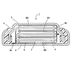
- FIG. 9 and 10 schematically show other examples of the non-aqueous secondary battery of the present invention.
- the battery 1 shown in FIG. 9 and FIG. 10 is a flat non-aqueous secondary battery having an electrode group formed by forming a joint portion at the periphery of two separators 7 and 7 arranged on both surfaces of the positive electrode 5. is there.
- FIG. 9 is a longitudinal sectional view showing a cross section of the battery case (the outer case 2 and the sealing case 3) and the insulating gasket 4 part of the battery.
- FIG. 10 is an enlarged view of the main part of FIG. It is a cross section.
- FIG. 11 schematically shows a plan view of a separator in which a joining portion is formed on a part of the peripheral edge.
- the positive electrode 5 disposed below the separator 7 is indicated by a dotted line.
- a current collecting tab portion 6b related to the negative electrode disposed on the lower side is indicated by a one-dot chain line, and a binding tape 9 for suppressing positional deviation of each component related to the electrode group is indicated by a two-dot chain line.
- the positive electrode 5 shown in FIG. 11 has both sides (both sides) opposed to the negative electrode in the electrode group.
- the upper side of the separator 7 In the forward direction), at least a negative electrode is arranged.
- the separator 7 shown in FIG. 11 is joined to another separator disposed on the lower side (depth direction in the drawing) via the positive electrode 5 (indicated by a dotted line in the drawing), and a joint 7c (see FIG. Middle). That is, the separator 7 and the separator disposed below the separator 7 are welded to each other at the peripheral edge to form a bag shape, and the positive electrode 5 is accommodated therein.
- the separator 7 shown in FIG. 11 includes a main body part 7a (that is, a main body part 7a having a larger area in plan view than the main body part 5a of the positive electrode 5) and the main body part 7a. It has a protruding portion 7b that protrudes and covers at least a portion of the current collecting tab portion 5b of the positive electrode 5 that includes a boundary portion with the main body portion 5a. Then, two separators (the separator 7 and the separator disposed below the positive electrode 5) disposed on both surfaces of the positive electrode 5 were welded to at least a part of the peripheral portion of the main body portion 7 a of the separator 7. A joint 7c is provided.
- separators for non-aqueous secondary batteries As separators for non-aqueous secondary batteries, a microporous film made of a thermoplastic resin that is easily heat-shrinkable at high temperatures is generally used. In this way, two sheets arranged on both sides of the positive electrode are used. In this separator, the peripheral portions are welded to each other to form a joint portion, so that, for example, even if the inside of the battery becomes high temperature, the thermal contraction of the separator is suppressed, so that a safer battery is configured. be able to.
- positioned on both surfaces of a positive electrode is a peripheral part of the main-body part of a separator
- a joining portion may also be provided at the peripheral portion of the separator overhanging portion (the portion of the peripheral edge portion of the separator overhanging portion along the protruding direction from the main body portion).
- the joining portion may be formed by directly welding the peripheral portions of the two separators, but a layer made of a thermoplastic resin is interposed between the two separators, and two sheets are interposed via this layer.
- the separator may be formed by welding. However, in the latter case, depending on the type of thermoplastic resin that constitutes the layer interposed between the separators and the type of thermoplastic resin that constitutes the separator, the strength of the joint may be reduced. It is preferable to use the layer made of the same kind of resin as the thermoplastic resin constituting the separator.
- the strength of the joint is determined by the strength of the separator itself. Since they are almost the same, for example, separation at a joint portion that may occur due to vibration or the like when the battery is used can be satisfactorily suppressed, and a battery with higher reliability can be obtained.
- the peripheral part which concerns on the main-body part of a separator may be a junction part, for example, it shows in FIG.
- the positive electrode is accommodated therein, the positive electrode is disposed on one separator, and the separator is further disposed on the positive electrode.
- air may remain in the separator.
- the number is preferably about 1 to 5 from the viewpoint of suppressing the decrease in battery productivity.
- the length of the outer edge of the non-welding part related to the main part of the separator is the total length of the outer edge related to the main part of the separator (the total length of the outer edge excluding the overhanging part). It is preferably about 15 to 60%. That is, in the main part of the separator, it is preferable that 40% or more (preferably 70% or more) of the entire length of the outer edge is a joined part, thereby ensuring good joining strength between the separators. Can do.
- a layer composed of the same kind of resin as the constituent resin of the separator is interposed between the two separators and these are welded to form a joint, for example, the joint on one separator
- a film to be the layer is placed at a place where the layer is expected to be placed, a positive electrode is disposed on the separator, and a separator is further stacked thereon, and then the peripheral portions of these separators are welded.
- a film to be the layer is placed in a place where it is planned to be a joint on one separator, and the separator and the film are welded in advance.
- Adopting a method of laminating the peripheral portion by overlapping, or a method of inserting a positive electrode between these separators after forming a joined portion by interposing a film serving as the layer between two separators. You can also.
- the peripheral edge of the separator can be welded by, for example, a hot press.
- the heating temperature may be a temperature higher than the melting point of the thermoplastic resin constituting the separator, but for example, it is preferably performed at a temperature 10 to 50 ° C. higher than the melting point.
- the heating press time is not particularly limited as long as a good joint can be formed, but is usually about 1 to 10 seconds.
- planar shape of the separator used for the battery of the present invention is, for example, at least a part of the peripheral part of the separator as described above at least at the joint part (at least the peripheral part of the two separators arranged on both surfaces of the positive electrode).
- the shape shown in FIG. 9 is preferable.
- separators are arranged on both sides of the positive electrode at least on both sides facing the negative electrode, but only the positive electrode arranged on the outermost side of the electrode group, that is, only one side (one side).
- separators may be disposed on both sides thereof (joint portions may be formed on these two separators), or only on the surface facing the negative electrode. You may arrange.
- the battery case that also serves as the negative electrode terminal and the outermost positive electrode of the electrode group are between As described above, an insulator such as an insulating seal made of tape or the like made of PET or polyimide is disposed.
- the separator is made of a microporous film made of thermoplastic resin.
- thermoplastic resin for example, polyolefins such as polyethylene (PE), polypropylene (PP), ethylene-propylene copolymer, and polymethylpentene are preferable.
- the melting point that is, the melting temperature measured using a differential scanning calorimeter (DSC) according to the provisions of JIS K 7121 is 100.
- DSC differential scanning calorimeter
- a polyolefin of ⁇ 180 ° C. is more preferred.
- microporous film made of the thermoplastic resin constituting the separator any form may be used as long as it has an ionic conductivity sufficient to obtain the required battery characteristics.
- the ion-permeable microporous film (microporous film currently used widely as a battery separator) which has many holes formed by the wet extending
- the thickness of the separator is preferably 5 to 25 ⁇ m, for example, and the porosity is preferably 30 to 70%, for example.
- the positive electrode, the negative electrode, and the separator are stacked and used as a stacked electrode group as shown in FIGS. 1, 9, and 10.
- the current collecting tab portion of each positive electrode is a plane of the electrode group. It is preferable that they are arranged so as to face the same direction as viewed, and the current collecting tab portions of the respective negative electrodes are arranged so as to face the same direction when seen in a plan view of the electrode group. Thereby, current collection of the positive electrode and the negative electrode becomes easier.
- the current collecting tab portion of each positive electrode and the current collecting tab portion of each negative electrode only need to be arranged so as not to contact each other in a plan view of the electrode group, but these contacts are better suppressed, And from the viewpoint of making the production of the battery better, as shown in FIG. 11, the current collecting tab portion 5b of each positive electrode and the current collecting tab portion 6b of each negative electrode face each other in a plan view of the electrode group. More preferably, it is arranged at a position where
- the electrode group formed by laminating the positive electrode, the negative electrode, and the separator is bound to the outer periphery with a binding tape 9 made of polypropylene or the like having chemical resistance. It is preferable to suppress misalignment of the (positive electrode, negative electrode and separator).
- the total number of positive electrodes and negative electrodes in the electrode group is at least 3, but it is also possible to use more than that (4, 5, 6, 7, 8, etc.). However, if the number of stacked positive and negative electrodes is increased too much, the merit as a flat battery may be reduced. Therefore, it is usually preferable that the number is 40 or less.
- non-aqueous electrolytes for batteries include cyclic carbonates such as ethylene carbonate (EC), propylene carbonate, butylene carbonate, and vinylene carbonate; chain carbonate esters such as dimethyl carbonate, diethyl carbonate (DEC), and methyl ethyl carbonate. 1,2-dimethoxyethane, diglyme (diethylene glycol methyl ether), triglyme (triethylene glycol dimethyl ether), tetraglyme (tetraethylene glycol dimethyl ether), 1,2-dimethoxyethane, 1,2-diethoxymethane, tetrahydrofuran, etc.
- An electrolyte prepared by dissolving an electrolyte (lithium salt) in a concentration of about 0.3 to 2.0 mol / L in an organic solvent such as ether; Kill.
- organic solvents may be used alone or in combination of two or more.
- electrolyte examples include LiBF 4 , LiPF 6 , LiAsF 6 , LiSbF 6 , LiClO 4 , LiCF 3 SO 3 , LiC 4 F 9 SO 3 , LiN (CF 3 SO 2 ) 2 , LiN (C 2 F 5 SO 2 ) Lithium salts such as 2 are mentioned.
- the non-aqueous electrolyte may be used in the non-aqueous secondary battery of the present invention in the form of a gel (gel electrolyte) by adding a known gelling agent such as a polymer.
- the planar shape of the nonaqueous secondary battery of the present invention is not particularly limited.
- the non-aqueous secondary battery of the present invention is a flat non-aqueous secondary battery having an exterior body composed of an exterior case, a sealing case, and an insulating gasket
- a conventionally known flat battery In addition to a circular shape, which is the mainstream, a polygonal shape such as a square (quadrangle) can be used.
- a planar shape required according to the application (polygonal shape such as a circle or a quadrangle) It can be.
- the polygon such as a square as the planar shape of the battery in this specification includes a shape in which the corner is cut off and a shape in which the corner is curved.
- the planar shape of the main body of the positive electrode and the negative electrode may be a shape corresponding to the planar shape of the battery, and may be substantially circular, rectangular or square.
- the portion corresponding to the location where the current collecting tab portion of the counter electrode is disposed is in contact with the current collecting tab portion of the counter electrode. In order to prevent this, it is preferable to use a cut-off shape as shown in FIGS.
- the outer case also serves as the positive electrode terminal and the sealing case also serves as the negative electrode terminal.
- the non-aqueous secondary battery of the present invention is limited to this. Instead, the outer case may also serve as the negative electrode terminal, and the sealing case may also serve as the positive terminal if necessary.
- FIGS. 1 to 11 are for facilitating understanding of the present invention.
- the size ratio is not always accurate.
- the non-aqueous secondary battery of the present invention is not particularly limited in size, but in the case of a flat non-aqueous secondary battery having an exterior body composed of an exterior case, a sealing case, and an insulation gasket, for example, insulation
- an insulation gasket for example, insulation
- the opening area of the gasket is a very small size such as 100 mm 2 or less, the influence of the shape of the end portion of the electrode mixture layer and the displacement of the electrode mixture layer on both sides of the current collector on the battery capacity is particularly large. Therefore, the effect produced by the present invention becomes more remarkable.
- the opening area of the insulating gasket according to the nonaqueous secondary battery of the present invention is, for example, 20 mm 2 or more. Is preferred.
- Example 1 Preparation of positive electrode> A positive electrode was prepared using LiCoO 2 as a positive electrode active material, carbon black as a conductive additive, and PVDF as a binder. First, a binder solution in which LiCoO 2 : 93 parts by mass and carbon black: 3 parts by mass were mixed, and the resulting mixture and PVDF: 4 parts by mass were previously dissolved in N-methyl-2-pyrrolidone (NMP). Were mixed to prepare a positive electrode mixture layer forming paste.
- NMP N-methyl-2-pyrrolidone
- a mold having a hole with an inclination angle of 85 ° was placed on one surface of an aluminum foil having a thickness of 15 ⁇ m serving as a positive electrode current collector so that the surface having a wider opening area was on the aluminum foil side.
- the positive electrode mixture layer forming paste placed on the mold was filled in the holes while being scraped with a squeegee and dried.
- a mold having the same shape as described above was placed on the other surface of the aluminum foil, and the positive electrode mixture layer forming paste was filled in the holes in the same manner as in the case of the one surface of the aluminum foil, followed by drying.
- the integrated product of the aluminum foil and the positive electrode mixture layer from which the mold has been removed is roll-pressed, and subsequently, in the shape shown in FIG. 2, the diameter of the arc portion of the main body portion having the positive electrode mixture layer is 6 mm, A portion of the aluminum foil was punched out so that the width of the current collecting tab portion composed of the exposed portion of the current collector (aluminum foil) was 3 mm to obtain a positive electrode.
- the thickness of the positive electrode mixture layer was 70 ⁇ m per side of the current collector, the angles A and A ′ shown in FIG. 4 were 85 °, and the length of a shown in FIG. It was 05 mm.
- a PE microporous membrane separator (thickness 16 ⁇ m) having the shape shown in FIG. 11 is disposed on both surfaces of the positive electrode, and the portions shown in FIG. 11 are welded by a hot press (temperature 170 ° C., press time 2 seconds).
- a joining part was formed in a part of a peripheral part of a main part concerning a sheet of separator, and a part of a peripheral part of an overhanging part, and a positive electrode and a separator were unified.
- the width of the joint portion relating to the two separators was 0.3 mm for both the main portion and the overhang portion, and the length in the protruding direction from the main portion at the peripheral portion of the overhang portion was 1.0 mm. Of the outer edges of the main parts of the two separators, 92% of the length was used as the joint.
- a negative electrode was produced using graphite as the negative electrode active material and PVDF as the binder.
- the negative electrode mixture layer forming paste was prepared by mixing 94 parts by mass of graphite, 6 parts by mass of PVDF, and a binder solution previously dissolved in NMP.
- a mold having a hole with an inclination angle of 85 ° was placed on one side of a 10 ⁇ m-thick copper foil serving as a negative electrode current collector so that the surface with the wider opening area was the copper foil side. Then, using the negative electrode mixture layer forming paste, a negative electrode mixture layer is formed on the surface of the copper foil in the same manner as in the case of the positive electrode.
- the diameter of the arc portion of the main body portion having the negative electrode mixture layer is 8 mm
- the width of the current collecting tab portion formed by the exposed portion of the current collector (copper foil) is A negative electrode of 3 mm was obtained.
- the thing which has a negative mix layer on only one side of a collector, and the thing which has a negative mix layer on both sides of a collector were produced.
- a part of the negative electrode having the negative electrode mixture layer on one side of the current collector was punched after a PET film having a thickness of 100 ⁇ m was attached to the exposed surface of the current collector.
- the obtained negative electrode has a negative electrode mixture layer having a negative electrode mixture layer only on one side of the current collector and a negative electrode mixture layer only on both sides of the current collector. It was 100 ⁇ m per one side, and the angle of B (negative electrode having a negative electrode mixture layer on one side and negative electrode having both sides) and B ′ (negative electrode having a negative electrode mixture layer on both sides) shown in FIG. 5 was 85 °.
- the negative electrode which has a negative mix layer on both surfaces of a collector was 0.05 mm in length of b shown in FIG.
- the sheet is made by adhering a PET film to the exposed surface of the current collector), and the positive electrode and the negative electrode are formed so that the negative electrode having the negative electrode mixture layer formed on one surface of the current collector becomes the outermost electrode.
- the current collecting tab portions of each positive electrode are collectively welded and integrated, and the current collecting tab portions of each negative electrode are collectively welded and integrated, and then the whole is stopped with a binding tape to obtain an electrode group. .
- the electrode group was placed in the outer case so that the PET film side faced the inner surface of the outer case (positive electrode case), and the integrated current collecting tab portion of each positive electrode was welded to the inner surface of the outer case.
- an insulating gasket is attached to the sealing case (negative electrode case), and the nonaqueous electrolyte (LiPF 6) is dissolved in a mixed solvent of ethylene carbonate and methyl ethyl carbonate in a volume ratio of 1: 2 at a concentration of 1.2 mol / l.
- cover the outer case containing the electrode group caulk the periphery, the diameter is 8.5 mm, the thickness is 5.4 mm, and the number of positive and negative electrodes in the electrode group is different. 9 and a flat non-aqueous secondary battery having the same structure as that shown in FIG. 10 was obtained.
- Comparative Example 1 The same positive electrode mixture layer forming paste as that used in Example 1 was intermittently applied to the surface of a long aluminum foil having a thickness of 15 ⁇ m, dried, roll-pressed, and then cut. A positive electrode having the same shape as that produced and having a positive electrode mixture layer having the same thickness on both sides of the current collector was produced. The obtained positive electrode had an angle of A and A ′ shown in FIG. 4 of 3 °, and the length of a shown in FIG. 4 was 0.8 mm.
- Example 2 the same negative electrode mixture layer forming paste as that used in Example 1 was intermittently applied to the surface of a long copper foil having a thickness of 10 ⁇ m, dried, roll-pressed, and cut.
- a negative electrode having the same shape as that prepared in 1 and having a negative electrode mixture layer having the same thickness on one side or both sides of the current collector was produced.
- the obtained negative electrode had an angle of B and B ′ shown in FIG. 5 of 3 °, and the length of b shown in FIG. 5 was 0.8 mm.
- a flat nonaqueous secondary battery was produced in the same manner as in Example 1 except that the positive electrode and the negative electrode were used.
- Comparative Example 2 A positive electrode and a negative electrode were produced in the same manner as in Example 1 except that the mold used for forming the positive electrode mixture layer related to the positive electrode and the negative electrode mixture layer related to the negative electrode was changed to one having a hole inclination angle of 90 °. As a result, when the mold was removed after the paste was filled in the mold holes and dried, cracks occurred at the ends of the mixture layer (positive electrode mixture layer and negative electrode mixture layer). . When a flat non-aqueous secondary battery is manufactured using such a positive electrode and a negative electrode, there is a high possibility that cracking will occur at the end of the mixture layer with reduced strength. If a crack occurs, it may cause a short circuit, resulting in a flat non-aqueous secondary battery that is determined to be defective. Therefore, in Comparative Example 2, the production of the flat non-aqueous secondary battery was stopped.
- Table 1 shows the inclination angle of the holes according to the mold used for the production of the positive electrode and the negative electrode, the angles A and A ′ shown in FIG. 4 of the positive electrode mixture layer (in Table 1, “end of the positive electrode mixture layer” 4) of the positive electrode mixture layer (described as “positional displacement of the positive electrode mixture layer” in Table 1) and B shown in FIG. 5 of the negative electrode mixture layer. And the angle of B ′ (described as “end slope of negative electrode mixture layer” in Table 1), and the length of b of the negative electrode mixture layer shown in FIG. 5 (in Table 1, “the negative electrode mixture layer Also described as “positional deviation”.
- the flat non-aqueous secondary battery of Example 1 has a higher capacity than the battery of Comparative Example 1.
- the flat non-aqueous secondary battery of the present invention can be applied to the same applications as conventionally known flat non-aqueous secondary batteries.
Landscapes
- Chemical & Material Sciences (AREA)
- Chemical Kinetics & Catalysis (AREA)
- Electrochemistry (AREA)
- General Chemical & Material Sciences (AREA)
- Engineering & Computer Science (AREA)
- Inorganic Chemistry (AREA)
- Manufacturing & Machinery (AREA)
- Materials Engineering (AREA)
- Physics & Mathematics (AREA)
- Condensed Matter Physics & Semiconductors (AREA)
- General Physics & Mathematics (AREA)
- Battery Electrode And Active Subsutance (AREA)
- Secondary Cells (AREA)
- Cell Separators (AREA)
Abstract
【課題】 積層型の電極群を備えており、高容量で生産性の良好な非水二次電池を構成し得る電極、その製造方法、および前記電極を有する積層型の電極群を備える非水二次電池を提供する。 【解決手段】 本体部と、平面視で、本体部から突出した集電タブ部とを有しており、本体部には、集電体の片面または両面に電極活物質を含む電極合剤層が形成されており、集電タブ部では、集電体に電極合剤層が形成されておらず集電体が露出しており、電極合剤層の、集電体の露出部との境界部分における側面と、電極合剤層における集電体と接する面との間の角度が、45°以上90°未満である非水二次電池用電極と、正極および/または負極が、本発明の電極である非水二次電池により、前記課題を解決する。本発明の非水二次電池用電極は、孔の側面が傾斜している型を用いて電極合剤層を形成する本発明法により製造できる。
Description
本発明は、積層型の電極群を備えており、高容量で生産性の良好な非水二次電池を構成し得る電極、その製造方法、および前記電極を有する積層型の電極群を備える非水二次電池に関するものである。
例えば、扁平形非水二次電池では、正極および負極に、集電体の片面または両面に正極合剤層や負極合剤層を形成し、かつ集電体の一部を、正極合剤層や負極合剤層を形成せずに露出させ、これを集電タブとして利用し、各正極および各負極の集電タブを、それぞれ纏めて溶接などし、これらの纏めた集電タブを、端子を兼ねる外装ケースや封口ケースの内面との電気的接続に利用しているものがある(例えば、特許文献1)。
ところで、非水二次電池の電極は、電極活物質(正極活物質や負極活物質)などを溶剤に分散させて調製した電極合剤層形成用組成物を、集電体の片面または両面に塗布し、乾燥するなどして電極合剤層(正極合剤層や負極合剤層)を形成する工程を経て製造することが一般的である(例えば、特許文献2)。
また、前記の製法の他にも、スクリーン印刷法を利用した非水二次電池用電極の製造方法の提案もある(特許文献3)。
ところが、特許文献2に記載されているような方法で製造した電極では、集電体に塗布した電極合剤層形成用組成物の端部で厚みムラが生じやすいため、乾燥後の電極合剤層の、平面視での中央部分の厚みと端部の厚みとが違ってしまい、例えば、電極合剤層の端部の近傍では、より端部に近い部分ほど薄くなる傾向がある。特に、集電タブ部となる集電体の露出部を、電極合剤層形成用組成物を塗布しない方法で設けて電極を製造する場合には、集電タブ部となる集電体の露出部との境界部分近傍での電極合剤層の厚みが、電極合剤層の他の部分よりも薄くなりやすい。
例えば、円筒形の電池や角筒形の電池では、正極と負極とをセパレータを介して重ね、渦巻状に巻回した巻回構造の電極体を使用することが多いが、このような電池に比べて、積層型の電極群を備える電池では、電極合剤層における集電体の露出部との境界部分の近傍での厚みの減少が、容量に大きく影響する。
こうしたことから、積層型の電極群を備える非水二次電池の高容量化を図るにあたっては、電池に使用される電極に係る電極合剤層の、平面視における中央部分と端部とでの厚みの変動を小さくする技術の開発が求められる。
本発明は、前記事情に鑑みてなされたものであり、その目的は、積層型の電極群を備えており、高容量で生産性の良好な非水二次電池を構成し得る電極、その製造方法、および前記電極を有する積層型の電極群を備える非水二次電池を提供することにある。
前記目的を達成し得た本発明の非水二次電池用電極は、複数の電極がセパレータを介して略平行(平行を含む)に積層された電極群を有する非水二次電池に用いられる電極であって、本体部と、平面視で、前記本体部から突出した集電タブ部とを有しており、前記本体部には、集電体の片面または両面に電極活物質を含む電極合剤層が形成されており、前記集電タブ部では、集電体に電極合剤層が形成されておらず集電体が露出しており、前記電極合剤層の、前記集電体の露出部との境界部分における側面と、前記電極合剤層における集電体と接する面との間の角度が、45°以上90°未満であることを特徴とするものである。
本発明の非水二次電池用電極は、集電体の表面に電極合剤層形成用の型を配置して、電極活物質および溶剤を含有する電極合剤層形成用組成物を前記型の孔に充填し、乾燥した後に前記型を外す工程を有しており、前記型の孔は、その側面が、集電体側の開口面積が集電体とは反対側の開口面積よりも大きくなるように傾斜していることを特徴とする本発明の非水二次電池用電極の製造方法により、製造することができる。
また、本発明の非水二次電池は、正極と負極とがセパレータを介して交互に、かつ略平行(平行を含む)に積層されており、正極および負極の合計枚数が3枚以上である電極群と、非水電解液とを有しており、前記正極は、平面視で、前記本体部から突出した集電タブ部とを有しており、前記本体部には、集電体の片面または両面に正極活物質を含む正極合剤層が形成されており、前記集電タブ部では、集電体に正極合剤層が形成されておらず集電体が露出しており、前記負極は、平面視で、前記本体部から突出した集電タブ部とを有しており、前記本体部には、集電体の片面または両面に負極活物質を含む負極剤層が形成されており、前記集電タブ部では、集電体に負極剤層が形成されておらず集電体が露出しており、前記正極および/または前記負極が、本発明の非水二次電池用電極であることを特徴とするものである。
本発明によれば、積層型の電極群を備えており、高容量で生産性の良好な非水二次電池を構成し得る電極、その製造方法、および前記電極を有する積層型の電極群を備える非水二次電池を提供することができる。すなわち、本発明の非水二次電池では、高容量で、生産性が良好である。
図1に、本発明の非水二次電池の一例を模式的に表す縦断面図を示す。図1に示す非水二次電池1は扁平形非水二次電池であり、複数の正極5および複数の負極6(6A、6B)を、セパレータ7を介して、それらの平面が電池の扁平面に略平行(平行を含む)となるように積層した積層型の電極群と、非水電解液(図示しない)とが、外装ケース2、封口ケース3および絶縁ガスケット4により形成される空間(密閉空間)内に収容されている。封口ケース3は、外装ケース2の開口部に絶縁ガスケット4を介して嵌合しており、外装ケース2の開口端部が内方に締め付けられ、これにより絶縁ガスケット4が封口ケース3に当接することで、外装ケース2の開口部が封口されて電池内部が密閉構造となっている。そして、積層型の電極群は、正極5、負極6およびセパレータ7の積層面が、電池の扁平面、すなわち外装ケース2および封口ケース3の扁平面に略平行(平行を含む)となるように、外装ケース2と封口ケース3と絶縁ガスケット4とで構成される外装体内に収容されている。外装ケース2および封口ケース3は、ステンレス鋼などの金属製であり、絶縁ガスケット4は、ナイロンなどの絶縁性を有する樹脂製である。
図1に示す扁平形非水二次電池1の有する正極5および負極6は、いずれも本発明の非水二次電池用電極である。
図2に正極5の平面図を模式的に示している。正極5は、本体部5aと、平面視で、本体部5aから突出した集電タブ部5bとを有している。集電タブ部5bは、通常、図2に示すように、その幅(図2中上下方向の長さ)を本体部5aの幅よりも狭くする。
図1および図2に示すように、正極5の本体部5aは、集電体52の両面に、正極合剤層51が形成されている。そして、正極5の集電タブ部5bは、集電体52表面に正極合剤層51が形成されておらず、集電体52が露出している。なお、図1に示す電池に係る電極群では、最外部(図中上下両端)の電極がいずれも負極(負極6B)であり、正極5は、全てが両側(両面)でセパレータ7を介して負極6と対向しているために、集電体52の両面に正極合剤層51を有しているが、例えば、電極群の最外部の電極が正極の場合には、その最外部の正極は、集電体の片面(電池内側の面)にのみ正極合剤層を有する構造であってもよい。
また、図3に負極6の平面図を模式的に示している。負極6は、本体部6aと、平面視で、本体部6aから突出した集電タブ部6bとを有している。集電タブ部6bは、通常、図3に示すように、その幅(図3中上下方向の長さ)を本体部6aの幅よりも狭くする。
図1および図3に示すように、電極群の最外部に位置する負極6Bの本体部6aは、集電体62の片面(電池内側の面)にのみ負極合剤層61が形成されており、それ以外の負極6Aの本体部6aは、集電体62の両面に負極合剤層61が形成されている。更に、負極6A、6Bの集電タブ部6bは、集電体62表面に負極合剤層61が形成されておらず、集電体が露出している。
図4に、図2に示している正極5の縦断面の要部を模式的に表す拡大図を示す。図1に示す電池に係る正極5は、図4に示しているように、正極合剤層51の、集電体52の露出部との境界部分における側面(図4中511a、511b)と、正極合剤層51における集電体52と接する面(図4中512a、512b)との間の角度(図4中A、A’の角度)が、45°以上90°未満である。
また、図5に、図3に示している負極6の縦断面の要部を模式的に表す拡大図を示す。図1に示す電池に係る負極6は、図5に示しているように、負極合剤層61の、集電体62の露出部との境界部分における側面(図5中611a、611b)と、正極合剤層61における集電体62と接する面(図5中612a、612b)との間の角度(図5中B、B’の角度)が、45°以上90°未満である。
本発明の非水二次電池用電極は、図2~図5に示すように、本体部と、平面視で、本体部から突出した集電タブ部とを有しており、本体部には、集電体の片面または両面に電極活物質を含む電極合剤層(正極合剤層または負極合剤層)が形成されており、集電タブ部では、集電体に電極合剤層が形成されておらず集電体が露出しており、電極合剤層の、集電体の露出部との境界部分における側面と、電極合剤層における集電体と接する面との間の角度が、45°以上90°未満である。
前記の通り、電極活物質などの電極合剤層の構成材料を溶剤に分散させて調製した電極合剤層形成用組成物を、集電体に塗布する工程を経て電極を製造した場合、集電体の一部に電極合剤層を形成せずに露出部とすると、電極合剤層の、集電体の露出部との境界部分における側面がなだらかに傾斜するなどして、例えば、図4中におけるA、A’の角度や図5中におけるB、B’の角度が非常に小さくなりやすい。
例えば、巻回構造の電極群を有する電池に使用される電極のように、比較的長尺の帯状の場合には、集電体の露出部との境界部分における側面部分の、電極合剤層の全体に占める割合を非常に小さくできるため、前記側面がなだらかに傾斜することによる電池容量への影響は極めて小さい。しかしながら、本発明の非水二次電池のように、正極および負極の合計枚数を3枚以上積層して構成した電極群を有する場合には、各電極では、集電体の露出部との境界部分における側面部分の、電極合剤層の全体に占める割合が、比較的大きくなるため、電池容量の低下を引き起こしてしまう。
そこで、本発明の非水二次電池用電極では、電極合剤層(集電体の片面にのみ電極合剤層を有する場合は、この電極合剤層、集電体の両面に電極合剤層を有する場合は、これら両方の電極合剤層。電極合剤層について、特に断らない限り、以下同じ。)の、集電体の露出部との境界部分における側面と、電極合剤層における集電体と接する面との間の角度を、45°以上、好ましくは60°以上として、前記側面の形状に起因する電池容量の低下を可及的に抑制している。
また、後述するように、本発明の非水二次電池用電極は、集電体表面に型を配置し、前記型の孔に電極合剤層を形成するための組成物を充填し、乾燥する工程を経て製造することが好ましいが、電極合剤層の、集電体の露出部との境界部分における側面と、電極合剤層における集電体と接する面との間の角度を、90°未満、好ましくは86°以下とすることで、特に前記方法により製造する場合の電極の生産を高めることができる。
なお、本発明の非水二次電池用電極では、電極合剤層の側面のうち、集電体の露出部との境界部分における側面と、電極合剤層の集電体と接する面との間の角度が、前記の値にあればよく、電極合剤層の側面の他の部分と、電極合剤層の集電体と接する面との間の角度は、例えば90°であってもよい。ただし、電極の生産をより容易にする観点からは、図1に示すように、電極合剤層の全側面と、電極合剤層の集電体と接する面との間の角度が、前記の値(45°以上、好ましくは60°以上であって、90°未満、好ましくは86°以下)であることがより好ましい。
また、図1に示す電池に係る正極5は、図4に示しているように、集電体52の片面に形成された正極合剤層51(例えば、図中上側の正極合剤層51)における集電体52の露出部との境界部分と、集電体52の他面に形成された正極合剤層51(例えば、図中下側の正極合剤層51)における集電体52の露出部との境界部分との位置ずれ(図中aの長さ)が、0.1mm以下であることが好ましく、0.05mm以下であることがより好ましい。
更に、図1に示す電池に係る負極のうち、集電体の両面に負極合剤層を有する負極6Aは、図5に示しているように、集電体62の片面に形成された負極合剤層61(例えば、図中上側の負極合剤層61)における集電体62の露出部との境界部分と、集電体62の他面に形成された負極合剤層61(例えば、図中下側の負極合剤層61)における集電体62の露出部との境界部分との位置ずれ(図中bの長さ)が、0.1mm以下であることが好ましく、0.05mm以下であることがより好ましい。
すなわち、本発明の非水二次電池用電極では、集電体の両面に電極合剤層を有する場合、集電体の片面に形成された電極合剤層における集電体の露出部との境界部分と、集電体の他面に形成された電極合剤層における集電体の露出部との境界部分との位置ずれが、0.1mm以下であることが好ましく、0.05mm以下であることがより好ましい。
電極活物質などの電極合剤層の構成材料を溶剤に分散させて調製した電極合剤層形成用組成物を、集電体に塗布する工程を経て、集電体の表面に電極合剤層を有する電極を製造する場合、例えば、集電タブ部となる集電体の露出部を設けるために、長尺の集電体に電極合剤層を間欠塗布する手法が採用されることが多い。しかし、このような手法では、集電体の両面に電極合剤層を形成すると、集電体の片面と他面とにおいて、電極合剤層の、集電体の露出部との境界部分の位置を、ずれなく合わせることが困難である。
電極に係る集電体の両面に形成された両電極合剤層において、前記の位置ずれが大きくなると、例えば集電体の片側の電極合剤層の体積が小さくなって、電池設計時に想定した量の電極活物質を導入できなくなったり、正極と負極との対向面積が、電池設計時に想定した面積よりも小さくなったりして、電池容量の低下を引き起こす虞がある。また、前記の位置ずれが大きくなりすぎると、電池に使用できなく虞もある。
例えば、巻回構造の電極群を有する電池に使用される電極のように、比較的長尺の帯状の場合には、集電体の片面の電極合剤層における集電体の露出部との境界部分と、集電体の他面の電極合剤層における集電体の露出部との境界部分との位置が、多少ずれていても、電池容量への影響は極めて小さい。しかしながら、本発明の非水二次電池のように、正極および負極の合計枚数を3枚以上積層して構成した電極群を有する場合には、個々の電極のサイズが巻回構造の電極群に使用されるような帯状の電極に比べて小さいために、前記の位置ずれによる電池容量への影響が、巻回構造の電極群を有する電池に比べて大きくなる。
そこで、本発明の非水二次電池用電極においては、集電体の片面に形成された電極合剤層における前記集電体の露出部との境界部分と、集電体の他面に形成された電極合剤層における前記集電体の露出部との境界部分との位置ずれを、0.1mm以下となるようにすることが好ましく、0.05mm以下となるようにすることがより好ましい。これにより、前記の位置ずれによる電池容量の低下を可及的に抑制して、より高容量の非水二次電池を、より良好な生産性で製造できるようにすることが可能となる。
また、図6に、前記の位置ずれが0mmである正極5の縦断面の要部を模式的に表す拡大図を示しており、図7には、前記の位置ずれが0mmである負極6(集電体の両面に負極合剤層を有する負極6A)の縦断面の要部を模式的に表す拡大図を示している。図6および図7に示すように、本発明の非水二次電池用電極においては、集電体の片面に形成された電極合剤層における前記集電体の露出部との境界部分と、集電体の他面に形成された電極合剤層における前記集電体の露出部との境界部分との位置ずれを、0mmとすることが特に好ましい。
本発明の非水二次電池用電極は、例えば、電極活物質などの電極合剤層の構成材料を溶剤に分散させて調製した電極合剤層形成用組成物を、集電体の片面または両面に塗布し、乾燥し、更にプレス処理を施す工程を経て製造することができるが、本発明の製造方法により製造することが好ましい。
本発明の非水二次電池用電極の製造方法は、集電体表面に電極合剤層形成用組成物を塗布する際に、集電体の表面に電極合剤層形成用の型を配置し、そして電極合剤層形成用組成物を前記型の孔に充填し、その後に乾燥して、電極合剤層(正極合剤層51または負極合剤層61)を形成してから前記型を外す、いわゆるスクリーン印刷法を採用し、前記型として、集電体側の開口面積が集電体とは反対側の開口面積よりも大きくなるように、側面が傾斜している孔を有するものを使用する。
前記のスクリーン印刷法によれば、前記型によって電極合剤層形成用組成物の流動を抑えつつ乾燥して電極合剤層を成形することが可能となるため、電極合剤層の、集電体との露出部との境界部分における側面や、他の側面部分と、電極合剤層の集電体と接する面との間の角度を、45°以上、好ましくは60°以上に、良好に調節することができる。また、スクリーン印刷法であれば、図2や図3に示す平面形状の電極を製造する際に、例えば、前記のような従来の製造方法により製造した帯状電極を打ち抜く方法を採用する場合に比べて、廃棄する部分を大幅に低減できるため、電極の生産性、ひいてはこの電極を有する非水二次電池の生産性を高めることができる。
しかも、前記の孔を有する型を用いた場合には、孔内に電極合剤層形成用組成物を充填し、乾燥した後に、型を容易に外すことができるため、これにより、更に電極の生産性を高めることができる。なお、前記の孔を有する型を用いることで、電極合剤層の、集電体との露出部との境界部分における側面や、他の側面部分と、電極合剤層の集電体と接する面との間の角度は、90°未満、好ましくは86°以下となる。
なお、集電体の両面に電極合剤層を有する電極を製造する場合、通常のスクリーン印刷法では、集電体の片面に電極合剤層を形成し、その後、集電体の他面に電極合剤層を形成しようとしても、集電体の片面に不連続に電極合剤層が形成されることで、集電体と電極合剤層との一体化物に厚みムラが生じるため、この集電体の他面に電極合剤層形成用組成物を均一に塗布することが困難となり、良好な品質の電極を生産することができない。
よって、集電体の両面に電極合剤層を有する電極の場合には、まず、集電体の片面に前記型を配置し、その孔内に電極合剤層形成用組成物を充填して乾燥する工程(I)と、前記工程(I)で使用した前記型を外すことなく集電体の片面に配置したままで、集電体の他面に前記と同様の型を配置し、その孔内(集電体の他面に配置した型の孔内)に電極合剤層形成用組成物を充填して乾燥する工程(II)と、前記工程(II)の終了後に集電体の両面(前記片面および前記他面)に配置した型を外す工程(III)とを経て製造することが好ましい。この場合には、集電体の前記他面に電極合剤層形成用組成物を塗布する際に、集電体と、その前記片面に形成された電極合剤層との一体化物において、不連続に形成された電極合剤層による厚みムラの問題を回避して、良好な品質の電極を生産することが可能となる。
また、帯状の集電体に電極合剤層形成用組成物を間欠塗布して製造される帯状の電極から、例えば図2や図3に示す平面形状で、集電体の両面に電極合剤層を有する電極を製造する場合、集電体の片面側の電極合剤層の端部と、他面側の電極合剤層の端部との位置を、精度よく合わせることが容易ではないために、両方の電極合剤層の位置ずれを小さくすることが困難である。
しかしながら、前記の工程(I)から工程(III)を有する製造方法であれば、例えば、集電体の片面の電極合剤層形成用の型と、集電体の他面の電極合剤層形成用の型との位置決めを、機械的に行う(例えばピン止めするなど)ことが可能となることから、両方の電極合剤層の位置ずれを小さくして、前記の値とすることができる。そのため、前記の前記の工程(I)から工程(III)を有する製造方法を採用することで、集電体の両面に電極合剤層を有する電極の生産性、ひいてはこの電極を有する非水二次電池の生産性を更に高めることができ、かつ前記電池の容量低下も更に抑えることができる。
集電体の両面に電極合剤層を有する電極を製造する場合の各工程を、図8を用いてより具体的に説明する。工程(I)では、まず、集電体52(または集電体62)の片面に電極合剤層形成用の型100aを配置する[図8(a)]。そして、型100aの孔101に、電極合剤層形成用組成物を充填し、乾燥する[図8(b)]。この工程(I)によって、集電体(正極集電体52または負極集電体62)の片面に電極合剤層(正極合剤層51または負極合剤層61)を形成する。
続いて、工程(II)では、工程(I)で使用した前記型100aを、集電体52(または集電体62)の片面に配置したままで、この集電体52(または集電体62)の他面[図6中下側の面]に、電極合剤層形成用の型100bを配置する[図8(c)]。そして、型100bの孔101に、電極合剤層形成用組成物を充填し、乾燥する[図8(d)]。この工程(II)によって、集電体(正極集電体52または負極集電体62)の他面にも、電極合剤層(正極合剤層51または負極合剤層61)を形成する。
続いて、工程(III)では、工程(II)の終了後に、集電体52および集電体62の片面および他面に配置している型100a、100bを外す[図8(e)]。
本発明法で使用する電極合剤層形成用の型における孔の傾斜角[前記型の、孔における開口面積が小さい方の面と、孔の内壁との間の角度。図8(a)中のCの角度。以下同じ。]は、電極合剤層の、集電体の露出部との境界部分における側面と、電極合剤層の集電体と接する面との間の角度を前記の値に調節しやすくする観点から、45°以上であることが好ましく、60°以上であることがより好ましく、また、90°未満であることが好ましく、86°以下であることがより好ましい。
電極合剤層を形成し、前記型を外した後の電極には、プレス処理を施して電極合剤層の厚みや密度を調節することが好ましい。そして、集電体の片面または両面に電極合剤層を不連続に形成した電極の、集電体の露出部を切断して、所望の平面形状(例えば、図2や図3に示す平面形状)の電極を得ることができる。
本発明の非水二次電池用電極が正極の場合、電極合剤層、すなわち、正極合剤層は、正極活物質、導電助剤、バインダなどを含有する層である。
正極活物質としては、例えば、LixCoO2、LixNiO2、LixMnO2、LixCoyNi1-yO2、LixCoyM1-yO2、LixNi1-yMyO2、LixMnyNizCo1-y-zO2、LixMn2O4、LixMn2-yMyO4などのリチウム遷移金属複合酸化物などが挙げられる(ただし、前記の各リチウム遷移金属複合酸化物において、Mは、Mg、Mn、Fe、Co、Ni、Cu、Zn、AlおよびCrからなる群から選ばれる少なくとも1種の金属元素であり、0≦x≦1.1、0<y<1.0、2.0≦z≦2.2である。)。これらの正極活物質は1種単独で使用してもよく、2種以上を併用しても構わない。
また、正極合剤層に係る導電助剤としては、例えば、カーボンブラック、鱗片状黒鉛、ケッチェンブラック、アセチレンブラック、繊維状炭素などが挙げられる。更に、正極合剤層に係るバインダとしては、例えば、ポリテトラフルオロエチレン(PTFE)、ポリフッ化ビニリデン(PVDF)、カルボキシメチルセルロース、スチレンブタジエンラバーなどが挙げられる。
本発明の非水二次電池用電極が正極の場合に、その正極合剤層を形成するための正極合剤層形成用組成物には、例えば、正極活物質、導電助剤、バインダなどを水または有機溶剤に分散させて調製したペースト状やスラリー状のものを使用することができる。
正極合剤層の組成としては、例えば、正極合剤層の全構成成分100質量%中、正極活物質を75~90質量%、導電助剤を5~20質量%、バインダを3~15質量%とすることが好ましい。また、正極合剤層の厚みは、例えば、集電体の片面あたり30~200μmであることが好ましい。
正極の集電体としては、アルミニウムやアルミニウム合金で構成された金属箔、エキスパンドメタル、平織り金網などが好ましい。なお、正極の総厚みを小さくし、電池内における正極および負極の積層数を増やすことで正極合剤層と負極剤層(負極合剤層と、負極合剤で構成されていないが負極活物質を含有する層とを含む。負極合剤で構成されていない負極剤層については後述する。)との対向面積を大きくして、電池の負荷特性を高める観点からは、集電体には金属箔を使用することが好ましい。また、集電体の厚みは、例えば、8~20μmであることが好ましい。
本発明の非水二次電池用電極が負極の場合、電極合剤層、すなわち、負極合剤層は、負極活物質、バインダなどを含有する層である。
負極活物質としては、例えば、活物質に、リチウム、リチウム合金、リチウムイオンを吸蔵放出可能な炭素材料、チタン酸リチウムなどが挙げられる。
負極活物質に用い得るリチウム合金としては、例えば、リチウム-アルミニウム、リチウム-ガリウムなどのリチウムと可逆的に合金化するリチウム合金が挙げられ、リチウム含有量が、例えば1~15原子%であることが好ましい。また、負極活物質に用い得る炭素材料としては、例えば、人造黒鉛、天然黒鉛、低結晶性カーボン、コークス、無煙炭などが挙げられる。
負極活物質に用い得るチタン酸リチウムとしては、一般式LixTiyO4で表され、xとyがそれぞれ、0.8≦x≦1.4、1.6≦y≦2.2の化学量論数を持つチタン酸リチウムが好ましく、特にx=1.33、y=1.67の化学量論数を持つチタン酸リチウムが好ましい。前記一般式LixTiyO4で表されるチタン酸リチウムは、例えば、酸化チタンとリチウム化合物とを760~1100℃で熱処理することによって得ることができる。前記酸化チタンとしては、アナターゼ型、ルチル型のいずれも使用可能であり、リチウム化合物としては、例えば、水酸化リチウム、炭酸リチウム、酸化リチウムなどが用いられる。
負極合剤層に係るバインダには、正極合剤層に用い得るものとして先に例示した各種バインダを使用することができる。
また、負極合剤層には、必要に応じて導電助剤を含有させることもできる。負極合剤層に係る導電助剤には、正極合剤層に用い得るものとして先に例示した各種導電助剤を使用することができる。
本発明の非水二次電池用電極が負極の場合に、その負極合剤層を形成するための負極合剤層形成用組成物には、例えば、負極活物質およびバインダ、更には必要に応じて導電助剤などを水または有機溶剤に分散させて調製したペースト状やスラリー状のものを使用することができる。
負極活物質に炭素材料を用いる場合の負極合剤層の組成としては、例えば、負極合剤層の全構成成分100質量%中、炭素材料を80~95質量%、バインダを3~15質量%とすることが好ましく、また、導電助剤を併用する場合には、導電助剤を5~20質量%とすることが好ましい。他方、負極活物質にチタン酸リチウムを用いる場合の負極合剤層の組成としては、例えば、負極合剤層の全構成成分100質量%中、チタン酸リチウムを75~90質量%、バインダを3~15質量%とすることが好ましく、また、導電助剤を併用する場合には、導電助剤を5~20質量%とすることが好ましい。負極における負極合剤層の厚みは、例えば、集電体の片面あたり40~200μmであることが好ましい。
負極の集電体としては、銅や銅合金で構成された金属箔、エキスパンドメタル、平織り金網などが好ましい。なお、負極の総厚みを小さくし、電池内における正極および負極の積層数を増やすことで正極合剤層と負極剤層(負極合剤層を含む)との対向面積を大きくして、電池の負荷特性を高める観点からは、集電体には金属箔を使用することが好ましい。また、集電体の厚みは、例えば、5~30μmであることが好ましい。
本発明の非水二次電池は、正極および負極の少なくとも一方が本発明の非水二次電池用電極であればよいが、図1に示すように、正極および負極の両者が、本発明の非水二次電池用電極であることが好ましい。
本発明の非水二次電池において、正極および負極のいずれか一方が本発明の非水二次電池用電極である場合、他方の電極には、例えば、電極合剤層の、集電体の露出部との境界部分における側面と、電極合剤層における集電体と接する面との間の角度が、90°や45°未満の電極を用いることができる。また、正極が本発明の非水二次電池用電極の場合、負極には、負極活物質であるリチウムやリチウム合金の箔からなる負極剤層を集電体の片面または両面に圧着するなどして構成した電極を用いることもできる。
本発明の非水二次電池は、外装ケースと封口ケースと絶縁ガスケットとで構成される外装体(すなわち、外装ケースと封口ケースとが絶縁ガスケットを介してカシメ封口されて構成される外装体)を有する扁平形非水二次電池の形態や、金属ラミネートフィルムで構成されるラミネートフィルム外装体を有するラミネート形非水二次電池の形態を取ることができる。なお、電池業界においては、高さより径の方が大きい扁平形電池をコイン形電池と呼んだり、ボタン形電池と呼んだりしているが、そのコイン形電池とボタン形電池との間に明確な差はなく、本明細書でいう扁平形非水二次電池には、コイン形電池、ボタン形電池のいずれもが含まれる。
以下に、本発明の非水二次電池の代表的な実施形態である扁平形非水二次電池を中心に、本発明の非水二次電池の詳細を、図面に基づいて説明する。
図1に示す電池1では、電極群を構成する全ての正極5の集電タブ部5bが纏められており、これらが外装ケース2の内面と溶接されるか、または溶接されずに直接接触することで、電気的に接続している。すなわち、図1に示す電池では、外装ケースは正極端子を兼ねている。なお、纏められた正極5の各集電タブ部5bは、互いに溶接されていてもよく、溶接されていなくてもよいが、電池の製造時において、纏められた各集電タブ部5bがバラけることを抑制し得る点で、各集電タブ部5bは互いに溶接されていることが好ましい。
また、図1に示す電池1では、前記の通り、電極群の最外部(上下両端)が、集電体の片面(電池内側の面)にのみ負極合剤層を有する負極6B、6Bとなっており、電極群における図中下側の負極6Bの集電体の露出面が、封口ケース3の内面と溶接されるか、または溶接されずに直接接することで、電気的に接続している。すなわち、図1に示す電池では、封口ケース3は負極端子を兼ねている。
そして、電極群の有する全ての負極6(集電体62の両面に負極合剤層61が形成された負極6Aおよび集電体62の片面に負極合剤層61が形成された負極6B)は、それらの集電タブ部6bを介して互いに電気的に接続している。なお、各負極6の集電タブ部6bの接続は、例えば溶接により行うことができる。
なお、前記の通り、本発明の非水二次電池では、電極群の最外部の一方の電極または両方の電極を正極とすることもできる。本発明の非水二次電池が扁平形非水二次電池の場合には、電極群の最外部における正極の片面には正極合剤層を形成せずに集電体を露出させ、この集電体の露出面と正極端子を兼ねる電池ケース(例えば外装ケース)の内面とを、溶接したり、溶接することなく直接接触させたりして、電気的に接続してもよい。
また、図1に示す電池1では、電極群の最上部に位置する負極6Bと、外装ケース2とを絶縁する目的で、これらの間に、ポリオレフィンなどの熱融着性樹脂で構成されたフィルムや、ポリエチレンテレフタレート(PET)やポリイミドなどを基材とし、両面に粘着層を有する粘着テープなどからなる絶縁層8が配置されている。絶縁層の厚みは、例えば、50~150μmであることが好ましい。
本発明の非水二次電池では、正極の両面に配置された2枚のセパレータについて、それらの周縁部の少なくとも一部において、互いに溶着して接合部を形成することができる。
図9および図10に、本発明の非水二次電池の他の例を模式的に示す。図9および図10に示す電池1は、正極5の両面に配置された2枚のセパレータ7、7の周縁部に接合部を形成して構成した電極群を有する扁平形非水二次電池である。図9は、電池の電池ケース(外装ケース2および封口ケース3)および絶縁ガスケット4部分の断面を表す縦断面図であり、図10は図9の要部を拡大し、更に電極群の部分を断面にしたものである。
また、図11に、周縁部の一部に接合部を形成したセパレータの平面図を模式的に示す。なお、図11では、セパレータ7とともに、正極、負極およびセパレータが積層された積層型の電極群とした場合を想定して、セパレータ7の下に配置される正極5を点線で示し、それらの更に下側に配置される負極に係る集電タブ部6bを一点鎖線で示し、電極群に係る各構成要素の位置ずれを抑えるための結束テープ9を二点鎖線で示している。また、図11に示す正極5は、電極群において、その両側(両面)が負極と対向するものであり、図11では図示していないが、電極群とした場合、セパレータ7の上側(図中手前方向)には、少なくとも負極が配置される。
図11に示すセパレータ7は、正極5(図中点線で表示)を介してその下側(図中奥行き方向)に配置される他のセパレータと、その周縁部において互いに溶着した接合部7c(図中、格子模様で表示)を有している。すなわち、セパレータ7と、その下側に配置されたセパレータとは、周縁部で互いに溶着されて袋状となっており、その内部に正極5を収容している。
なお、図11に示すセパレータ7は、正極5の本体部5a全面を覆う主体部7a(すなわち、正極5の本体部5aよりも平面視での面積が大きな主体部7a)と、主体部7aから突出し、正極5の集電タブ部5bの、本体部5aとの境界部を少なくとも含む部分を覆う張り出し部7bとを有している。そして、セパレータ7の主体部7aの周縁部の少なくとも一部に、正極5の両面に配置された2枚のセパレータ(セパレータ7と、正極5の下側に配置されたセパレータ)同士を互いに溶着した接合部7cを設けている。
非水二次電池のセパレータには、高温下で熱収縮しやすい熱可塑性樹脂製の微多孔膜が使用されることが一般的であるが、このように、正極の両面に配置された2枚のセパレータにおいて、その周縁部を互いに溶着して接合部を形成することで、例えば、電池内が高温となっても、セパレータの熱収縮が抑制されるため、より安全性の高い電池を構成することができる。
なお、図11に示すように、主体部と張り出し部とを有するセパレータを使用する場合、正極の両面に配置された2枚のセパレータを接合するための接合部は、セパレータの主体部の周縁部に設ければよいが、セパレータの張り出し部の周縁部(セパレータの張り出し部の周縁部のうち、主体部からの突出方向に沿う部分)にも接合部を設けてもよい。
接合部は、2枚のセパレータの周縁部同士を直接溶着して形成してもよいが、2枚のセパレータの間に熱可塑性樹脂で構成される層を介在させ、この層を介して2枚のセパレータを溶着することにより形成してもよい。ただし、後者の場合、セパレータ間に介在させる層を構成する熱可塑性樹脂の種類と、セパレータを構成する熱可塑性樹脂の種類によっては、接合部の強度が小さくなる場合があるため、セパレータ間に介在させる層は、セパレータを構成する熱可塑性樹脂と同種の樹脂で構成されたものを使用することが好ましい。すなわち、セパレータ同士を直接溶着したり、セパレータを構成する熱可塑性樹脂と同種の樹脂で構成される層を介してセパレータ同士を溶着したりした場合には、接合部の強度がセパレータ自身の強度とほぼ同等となるため、例えば、電池の使用時に振動などによって生じる虞のある接合部での剥離が良好に抑制でき、更に信頼性の高い電池とすることができる。
なお、図11に示すように主体部と張り出し部とを有するセパレータを使用する場合、セパレータの主体部に係る周縁部は、全てが接合部となっていてもよいが、例えば、図11に示すように、周縁部の一部を、セパレータ同士を溶着せずに非溶着部7d、7dとして残してもよい。2枚のセパレータを溶着して袋状とした後に、その中に正極を収容したり、1枚のセパレータの上に正極を配置し、その正極の上に更にセパレータを配置して、セパレータの周縁部を溶着して袋状としたセパレータの中に正極を収容したりした場合、セパレータ内に空気が残留することがある。しかし、このような正極を用いて電池を製造すると、外装ケースと封口ケースとをかしめる際に、前記の残留空気が、非溶着部7d、7dを通じてセパレータ外へ良好に排出されるため、セパレータ内の残留空気による問題(発電時の反応が不均一になって容量向上効果が小さくなるなどの問題)の発生を防止できる。
セパレータの周縁部に非溶着部を設ける場合、電池の生産性の低下を抑える観点から、その個数は1~5個程度とすることが好ましい。また、セパレータの周縁部に非溶着部を設ける場合、セパレータの主体部に係る非溶着部の外縁の長さが、セパレータの主体部に係る外縁の全長さ(張り出し部を除く外縁の全長さ)の15~60%程度することが好ましい。すなわち、セパレータの主体部においては、その外縁の全長さのうちの40%以上(好ましくは70%以上)が接合部であることが好ましく、これにより、セパレータ同士の接合強度を良好に確保することができる。
2枚のセパレータの周縁部に接合部を形成するとともに、これらのセパレータの間に正極を収容するには、2枚のセパレータ同士を直接溶着して接合部を形成する場合では、例えば、1枚のセパレータ上に正極を重ね、更にその上にセパレータを重ねた後、これらのセパレータの周縁部を溶着する方法が採用できる。また、2枚のセパレータを重ね、これらの周縁部を溶着してセパレータ同士を接合し、その後、これらのセパレータ間に正極を挿入する方法を採用することもできる。
一方、2枚のセパレータ同士の間にセパレータの構成樹脂と同種の樹脂で構成された層を介在させ、これらを溶着して接合部を形成する場合では、例えば、1枚のセパレータ上の接合部となることが予定される箇所に前記層となるフィルムを置き、かつこのセパレータ上に正極を配置し、更にその上にセパレータを重ねた後、これらのセパレータの周縁部を溶着する方法が採用できる。また、1枚のセパレータ上の接合部となることが予定されている箇所に前記層となるフィルムを置き、このセパレータとフィルムとを予め溶着しておき、その後、このセパレータに正極、セパレータの順に重ねて周縁部を溶着する方法や、2枚のセパレータの間に前記層となるフィルムを介在させて溶着して接合部を形成した後に、これらのセパレータ間に正極を挿入する方法を採用することもできる。
セパレータの周縁部の溶着は、例えば、加熱プレスにより行うことができる。この場合、加熱温度は、セパレータを構成する熱可塑性樹脂の融点よりも高い温度であればよいが、例えば、融点より10~50℃高い温度で行うことが好ましい。また、加熱プレスの時間については、良好に接合部が形成できれば特に制限はないが、通常は、1~10秒程度とする。
なお、本発明の電池に使用するセパレータの平面形状は、例えば、前記のようにセパレータの周縁部の少なくとも一部に接合部(正極の両面に配置された2枚のセパレータに係る周縁部の少なくとも一部を、互いに溶着することにより形成する接合部)を形成する場合には、図9に示す形状であることが好ましいが、前記接合部を形成しない場合でも、図9に示す形状とすることが好ましい。
本発明の電池では、電極群の形成にあたり、少なくとも両側が負極と対向している正極の両面にはセパレータを配置するが、電極群の最外部側に配置される正極、すなわち片側(片面)のみが負極と対向している正極については、その両面にセパレータを配置してもよく(更に、これらの2枚のセパレータに接合部を形成してもよい)、負極と対向する面にのみセパレータを配置しても構わない。更に、電極群に係る最外部側の電極をいずれも正極とし、これらの正極の両面にセパレータを配置しない場合には、負極端子を兼ねる電池ケースと電極群の最外部の正極との間には、前記の通り、PETやポリイミドなどで形成されたテープなどからなる絶縁シールなどの絶縁体を配置する。
セパレータには、熱可塑性樹脂製の微多孔膜で構成されたものを使用する。セパレータを構成する熱可塑性樹脂としては、例えば、ポリエチレン(PE)、ポリプロピレン(PP)、エチレン-プロピレン共重合体、ポリメチルペンテンなどのポリオレフィンが好ましく、セパレータ同士を溶着したり、セパレータ間にセパレータの構成樹脂と同種の樹脂を配置して溶着したりする観点からは、その融点、すなわち、JIS K 7121の規定に準じて、示差走査熱量計(DSC)を用いて測定される融解温度が、100~180℃のポリオレフィンがより好ましい。
セパレータを構成する熱可塑性樹脂製の微多孔膜の形態としては、必要な電池特性が得られるだけのイオン伝導度を有していればどのような形態でもよいが、従来から知られている乾式または湿式延伸法などにより形成された孔を多数有するイオン透過性の微多孔膜(電池のセパレータとして汎用されている微多孔フィルム)が好ましい。
セパレータの厚みは、例えば、5~25μmであることが好ましく、また、空孔率は、例えば、30~70%であることが好ましい。
前記の正極、負極およびセパレータは、図1や図9、図10に示すように積層して積層型の電極群として使用するが、その際、各正極の集電タブ部が、電極群の平面視で同一方向を向くように配置され、かつ各負極の集電タブ部が、電極群の平面視で同一方向を向くように配置されていることが好ましい。これにより、正極および負極の集電がより容易となる。
更に、各正極の集電タブ部と、各負極の集電タブ部とは、電極群の平面視で互いに接触しないように配置されていればよいが、これらの接触をより良好に抑制し、かつ電池の生産をより良好にする観点からは、図11に示しているように、各正極の集電タブ部5bと各負極の集電タブ部6bとは、電極群の平面視で互いに対向する位置に配されていることがより好ましい。
また、正極、負極およびセパレータを積層して構成した電極群は、図11に示すように、その外周を、耐薬品性を有するポリプロピレンなどで構成された結束テープ9で結束して、各構成要素(正極、負極およびセパレータ)の位置ずれを抑制することが好ましい。
電極群に係る正極および負極は、少なくとも合計枚数が3枚であるが、それ以上(4枚、5枚、6枚、7枚、8枚など)とすることも可能である。ただし、正極および負極の積層数をあまり多くすると、扁平状電池としてのメリットが小さくなる虞があることから、通常は、40枚以下とすることが好ましい。
電池に係る非水電解液としては、例えば、エチレンカーボネート(EC)、プロピレンカーボネート、ブチレンカーボネート、ビニレンカーボネートなどの環状炭酸エステル;ジメチルカーボネート、ジエチルカーボネート(DEC)、メチルエチルカーボネートなどの鎖状炭酸エステル;1,2-ジメトキシエタン、ジグライム(ジエチレングリコールメチルエーテル)、トリグライム(トリエチレングリコールジメチルエーテル)、テトラグライム(テトラエチレングリコールジメチルエーテル)、1,2-ジメトキシエタン、1,2-ジエトキシメタン、テトラヒドロフランなどのエーテル;などの有機溶媒に、電解質(リチウム塩)を0.3~2.0mol/L程度の濃度に溶解させることによって調製した電解液を用いることができる。前記の有機溶媒は、それぞれ1種単独で用いてもよく、2種以上を併用しても構わない。
前記電解質としては、例えば、LiBF4、LiPF6、LiAsF6、LiSbF6、LiClO4、LiCF3SO3、LiC4F9SO3、LiN(CF3SO2)2、LiN(C2F5SO2)2などのリチウム塩が挙げられる。
また、前記の非水電解液は、ポリマーなどの公知のゲル化剤を添加してゲル状(ゲル状電解質)として、本発明の非水二次電池に使用してもよい。
本発明の非水二次電池の平面形状には特に制限は無い。例えば、本発明の非水二次電池が、外装ケースと封口ケースと絶縁ガスケットとで構成される外装体を有する扁平形非水二次電池の場合には、従来から知られている扁平形電池の主流である円形の他、角形(四角形)などの多角形状とすることができる。また、本発明の非水二次電池が、ラミネートフィルム外装体を有するラミネート形非水二次電池の場合には、その用途に応じて要求される平面形状(円形や四角形などの多角形状など)とすることができる。
なお、本明細書でいう電池の平面形状としての角形などの多角形には、その角が切り落とされた形状や、角を曲線にした形状も包含される。また、正極および負極(本発明の扁平形非水二次電池用電極を含む)の本体部の平面形状は、電池の平面形状に応じた形状とすればよく、略円形としたり、長方形や正方形などの四角形などの多角形とすることもできるが、例えば、略円形とする場合には、対極の集電タブ部が配置される箇所に相当する部分は、対極の集電タブ部との接触を防止するために、図2および図3に示すように切り落とした形状としておくことが好ましい。
図1、図9、図10では、外装ケースが正極端子を兼ね、封口ケースが負極端子を兼ねる扁平形非水二次電池を示しているが、本発明の非水二次電池はこれに限定されず、必要に応じて、外装ケースが負極端子を兼ね、封口ケースが正極端子を兼ねていてもよい。
これまで、図1~図11を用いて本発明について説明してきたが、これらの図面は、本発明の理解を容易にするためのものであり、図示されている各要素のサイズや各要素同士のサイズの比率は、必ずしも正確ではない。
本発明の非水二次電池は、そのサイズについては特に制限はないが、外装ケースと封口ケースと絶縁ガスケットとで構成される外装体を有する扁平形非水二次電池の場合、例えば、絶縁ガスケットの開口面積が100mm2以下といった非常に小さなサイズとする場合、電極合剤層の端部の形状や集電体の両面の電極合剤層の位置ずれの電池容量への影響が特に大きいことから、本発明により奏される効果がより顕著となる。ただし、絶縁ガスケットの開口面積があまり小さな電池は、それ自体生産が困難となる傾向にあるため、本発明の非水二次電池に係る絶縁ガスケットの開口面積は、例えば、20mm2以上であることが好ましい。
以下、実施例に基づいて本発明を詳細に述べる。ただし、下記実施例は、本発明を制限するものではない。
実施例1
<正極の作製>
正極活物質としてLiCoO2を、導電助剤としてカーボンブラックを、バインダとしてPVDFを、それぞれ用いて正極を作製した。まず、LiCoO2:93質量部とカーボンブラック:3質量部とを混合し、得られた混合物とPVDF:4質量部を予めN-メチル-2-ピロリドン(NMP)に溶解させておいたバインダ溶液とを混合して正極合剤層形成用ペーストを調製した。
<正極の作製>
正極活物質としてLiCoO2を、導電助剤としてカーボンブラックを、バインダとしてPVDFを、それぞれ用いて正極を作製した。まず、LiCoO2:93質量部とカーボンブラック:3質量部とを混合し、得られた混合物とPVDF:4質量部を予めN-メチル-2-ピロリドン(NMP)に溶解させておいたバインダ溶液とを混合して正極合剤層形成用ペーストを調製した。
正極集電体となる厚さ15μmのアルミニウム箔の片面に、傾斜角が85°の孔を有する型を、孔の開口面積がより広い側の面がアルミニウム箔側となるように載せた。そして、型の上に載せた前記の正極合剤層形成用ペーストを、スキージで掻きながら孔内に充填し、乾燥した。続いて、アルミニウム箔の他面に、前記と同じ形状の型を載せ、アルミニウム箔の前記片面の場合と同様にして孔内に正極合剤層形成用ペーストを充填し、乾燥した。その後、型を取り外したアルミニウム箔と正極合剤層との一体化物をロールプレスし、続いて、図2に示す形状で、正極合剤層を有する本体部の円弧の部分の直径が6mmで、集電体(アルミニウム箔)の露出部からなる集電タブ部の幅が3mmとなるように、アルミニウム箔の部分を打ち抜いて、正極を得た。得られた正極は、正極合剤層の厚みが集電体の片面あたり70μmであり、図4に示すAおよびA’の角度が85°であり、図4に示すaの長さが0.05mmであった。
<正極とセパレータとの一体化>
前記の正極の両面に、図11に示す形状のPE製微多孔膜セパレータ(厚み16μm)を配置し、図11に示す箇所を加熱プレス(温度170℃、プレス時間2秒)により溶着し、2枚のセパレータに係る主体部の周縁部の一部および張り出し部の周縁部の一部に接合部を形成して、正極とセパレータとを一体化した。なお、2枚のセパレータに係る接合部の幅は、主体部、張り出し部とも0.3mmとし、張り出し部の周縁部における主体部からの突出方向の長さは1.0mmとした。また、2枚のセパレータの主体部の外縁のうち、92%の長さ部分を接合部とした。
前記の正極の両面に、図11に示す形状のPE製微多孔膜セパレータ(厚み16μm)を配置し、図11に示す箇所を加熱プレス(温度170℃、プレス時間2秒)により溶着し、2枚のセパレータに係る主体部の周縁部の一部および張り出し部の周縁部の一部に接合部を形成して、正極とセパレータとを一体化した。なお、2枚のセパレータに係る接合部の幅は、主体部、張り出し部とも0.3mmとし、張り出し部の周縁部における主体部からの突出方向の長さは1.0mmとした。また、2枚のセパレータの主体部の外縁のうち、92%の長さ部分を接合部とした。
<負極の作製>
負極活物質として黒鉛を、バインダとしてPVDFを、それぞれ用いて負極を作製した。前記黒鉛:94質量部とPVDF:6質量部と予めNMPに溶解させておいたバインダ溶液とを混合して、負極合剤層形成用ペーストを調製した。
負極活物質として黒鉛を、バインダとしてPVDFを、それぞれ用いて負極を作製した。前記黒鉛:94質量部とPVDF:6質量部と予めNMPに溶解させておいたバインダ溶液とを混合して、負極合剤層形成用ペーストを調製した。
負極集電体となる厚さ10μmの銅箔の片面に、傾斜角が85°の孔を有する型を、孔の開口面積がより広い側の面が銅箔側となるように載せた。そして、前記の負極合剤層形成用ペーストを用い、正極の場合と同様にして銅箔の表面に負極合剤層を形成し、更に、正極の場合と同様にしてロールプレスおよび銅箔部分での打ち抜きを行って、図3に示す形状で、負極合剤層を有する本体部の円弧の部分の直径が8mmで、集電体(銅箔)の露出部からなる集電タブ部の幅が3mmである負極を得た。
なお、負極については、集電体の片面のみに負極合剤層を有するものと、集電体の両面に負極合剤層を有するものとを作製した。また、集電体の片面の負極合剤層を有する負極の一部については、集電体の露出面に厚みが100μmのPETフィルムを貼り付けた後に打ち抜いた。得られた負極は、負極合剤層の厚みが、集電体の片面のみに負極合剤層を有するもの、集電体の両面のみに負極合剤層を有するもののいずれも、集電体の片面あたり100μmであり、図5に示すB(負極合剤層を片面に有する負極および両面に有する負極)およびB’(負極合剤層を両面に有する負極)の角度が85°であった。また、集電体の両面に負極合剤層を有する負極は、図5に示すbの長さが0.05mmであった。
<電池の組み立て>
前記のセパレータと一体化した正極14枚と、集電体の両面に負極合剤層を形成した負極15枚と、集電体の片面に負極合剤層を形成した負極2枚(このうち1枚は、集電体の露出面にPETフィルムを貼り付けたもの)とを用い、集電体の片面に負極合剤層を形成した負極が最外部の電極になるように、正極と負極とを交互に重ねた。そして、各正極の集電タブ部を纏めて溶接して一体化し、また、各負極の集電タブ部を纏めて溶接して一体化した後、全体を結束テープで止めて電極群を得た。
前記のセパレータと一体化した正極14枚と、集電体の両面に負極合剤層を形成した負極15枚と、集電体の片面に負極合剤層を形成した負極2枚(このうち1枚は、集電体の露出面にPETフィルムを貼り付けたもの)とを用い、集電体の片面に負極合剤層を形成した負極が最外部の電極になるように、正極と負極とを交互に重ねた。そして、各正極の集電タブ部を纏めて溶接して一体化し、また、各負極の集電タブ部を纏めて溶接して一体化した後、全体を結束テープで止めて電極群を得た。
外装ケース内に前記の電極群を、PETフィルム側が外装ケース(正極ケース)内面と対向するように入れ、一体化した各正極の集電タブ部を外装ケース内面に溶接した。また、封口ケース(負極ケース)に絶縁ガスケットを装着し、非水電解液(LiPF6をエチレンカーボネートとメチルエチルカーボネートとの体積比1:2の混合溶媒に、1.2mol/lの濃度で溶解した溶液)40mgを入れた後、電極群を収容した外装ケースを被せ、周囲をかしめて、直径8.5mm、厚み5.4mmで、電極群に係る正極および負極の枚数が異なる以外は、図9および図10に示すものと同様の構造の扁平形非水二次電池を得た。
比較例1
実施例1で用いたものと同じ正極合剤層形成用ペーストを、厚さが15μmで長尺のアルミニウム箔の表面に間欠塗布し、乾燥し、ロールプレスした後に裁断して、実施例1で作製したものと同じ形状であり、かつ同じ厚みの正極合剤層を集電体の両面に有する正極を作製した。得られた正極は、図4に示すAおよびA’の角度が3°であり、図4に示すaの長さが0.8mmであった。
実施例1で用いたものと同じ正極合剤層形成用ペーストを、厚さが15μmで長尺のアルミニウム箔の表面に間欠塗布し、乾燥し、ロールプレスした後に裁断して、実施例1で作製したものと同じ形状であり、かつ同じ厚みの正極合剤層を集電体の両面に有する正極を作製した。得られた正極は、図4に示すAおよびA’の角度が3°であり、図4に示すaの長さが0.8mmであった。
また、実施例1で用いたものと同じ負極合剤層形成用ペーストを、厚さが10μmで長尺の銅箔の表面に間欠塗布し、乾燥し、ロールプレスした後に裁断して、実施例1で作製したものと同じ形状であり、かつ同じ厚みの負極合剤層を集電体の片面または両面に有する負極を作製した。得られた負極は、図5に示すBおよびB’の角度が3°であり、図5に示すbの長さが0.8mmであった。
前記の正極と前記の負極とを用いた以外は、実施例1と同様にして扁平形非水二次電池を作製した。
比較例2
正極に係る正極合剤層および負極に係る負極合剤層の形成時に用いた型を、孔の傾斜角が90°のものに変更した以外は、実施例1と同様にして正極および負極を作製したところ、型の孔内にペーストを充填し、乾燥した後の型の取り外しの際に、合剤層(正極合剤層および負極合剤層)の端部に割れの生じたものがあった。このような正極および負極を用いて扁平形非水二次電池を作製した場合には、強度が低下した合剤層の端部に割れが生じる可能性が高く、電池とした後に合剤層に割れが生じると短絡の原因となる可能性があり、不良と判断される扁平形非水二次電池となる。よって、比較例2では、扁平形非水二次電池の作製を中止した。
正極に係る正極合剤層および負極に係る負極合剤層の形成時に用いた型を、孔の傾斜角が90°のものに変更した以外は、実施例1と同様にして正極および負極を作製したところ、型の孔内にペーストを充填し、乾燥した後の型の取り外しの際に、合剤層(正極合剤層および負極合剤層)の端部に割れの生じたものがあった。このような正極および負極を用いて扁平形非水二次電池を作製した場合には、強度が低下した合剤層の端部に割れが生じる可能性が高く、電池とした後に合剤層に割れが生じると短絡の原因となる可能性があり、不良と判断される扁平形非水二次電池となる。よって、比較例2では、扁平形非水二次電池の作製を中止した。
実施例1および比較例1の非水二次電池各20個について、電流値3.6mAでの放電容量を測定した。これらの結果を表1に記載する。また、表1には、正極および負極の作製に用いた型に係る孔の傾斜角、正極合剤層の図4に示すAおよびA’の角度(表1では、「正極合剤層の端部勾配」と記載する)、正極合剤層の図4に示すaの長さ(表1では、「正極合剤層の位置ずれ」と記載する)、負極合剤層の図5に示すBおよびB’の角度(表1では、「負極合剤層の端部勾配」と記載する)、並びに負極合剤層の図5に示すbの長さ(表1では、「負極合剤層の位置ずれ」と記載する)も併記する。

表1に示す通り、実施例1の扁平形非水二次電池は、比較例1の電池に対して高容量である。
本発明の扁平形非水二次電池は、従来から知られている扁平形非水二次電池と同様の用途に適用することができる。
1 扁平形非水二次電池
2 正極ケース
3 負極ケース
4 絶縁ガスケット
5 正極
5a 正極の本体部
5b 正極の集電タブ部
6、6A、6B 負極
6a 負極の本体部
6b 負極の集電タブ部
7 セパレータ
7c 接合部
8 絶縁材
100 電極合剤層形成用の型
2 正極ケース
3 負極ケース
4 絶縁ガスケット
5 正極
5a 正極の本体部
5b 正極の集電タブ部
6、6A、6B 負極
6a 負極の本体部
6b 負極の集電タブ部
7 セパレータ
7c 接合部
8 絶縁材
100 電極合剤層形成用の型
Claims (10)
- 複数の電極がセパレータを介して略平行に積層された電極群を有する非水二次電池に用いられる電極であって、
本体部と、平面視で、前記本体部から突出した集電タブ部とを有しており、前記本体部には、集電体の片面または両面に電極活物質を含む電極合剤層が形成されており、前記集電タブ部では、集電体に電極合剤層が形成されておらず集電体が露出しており、
前記電極合剤層の、前記集電体の露出部との境界部分における側面と、前記電極合剤層における集電体と接する面との間の角度が、45°以上90°未満であることを特徴とする非水二次電池用電極。 - 電極合剤層の、集電体の露出部との境界部分における側面と、電極合剤層における集電体と接する面との間の角度が、86°以下である請求項1に記載の非水二次電池用電極。
- 集電体の両面に電極合剤層が形成されており、集電体の両面に形成された前記電極合剤層の、前記集電体の露出部との境界部分における側面と、前記電極合剤層における集電体と接する面との間の角度が、いずれも45°以上90°未満である請求項1に記載の非水二次電池用電極。
- 集電体の両面に形成された前記電極合剤層の、前記集電体の露出部との境界部分における側面と、前記電極合剤層における集電体と接する面との間の角度が、いずれも86°以下である請求項3に記載の非水二次電池用電極。
- 集電体の片面に形成された電極合剤層における集電体の露出部との境界部分と、集電体の他面に形成された電極合剤層における前記集電体の露出部との境界部分との位置ずれが、0.1mm以下である請求項3または4に記載の非水二次電池用電極。
- 正極と負極とがセパレータを介して交互に、かつ略平行に積層されており、正極および負極の合計枚数が3枚以上である電極群と、非水電解液とを有する非水二次電池であって、
前記正極は、平面視で、前記本体部から突出した集電タブ部とを有しており、前記本体部には、集電体の片面または両面に正極活物質を含む正極合剤層が形成されており、前記集電タブ部では、集電体に正極合剤層が形成されておらず集電体が露出しており、
前記負極は、平面視で、前記本体部から突出した集電タブ部とを有しており、前記本体部には、集電体の片面または両面に負極活物質を含む負極剤層が形成されており、前記集電タブ部では、集電体に負極剤層が形成されておらず集電体が露出しており、
前記正極および/または前記負極が、請求項1~5のいずれかに記載の非水二次電池用電極であることを特徴とする非水二次電池。 - 外装ケースと封口ケースとが絶縁ガスケットを介してカシメ封口されて形成された空間内に、電極群と非水電解液とが収容されており、前記電極群における正極、負極およびセパレータの積層面が、前記外装ケースおよび前記封口ケースの扁平面に略平行である請求項6に記載の非水二次電池。
- 少なくとも両側が負極と対向している正極の両面には、熱可塑性樹脂製の微多孔膜からなるセパレータが配置されており、
前記2枚のセパレータは、前記正極の本体部全面を覆う主体部と、前記主体部から突出し、前記正極の集電タブ部の、少なくとも本体部との境界部を含む部分を覆う張り出し部とを有しており、かつ前記2枚のセパレータは、その主体部の周縁部の少なくとも一部において、互いに溶着された接合部を有している請求項6または7に記載の扁平形非水二次電池。 - 請求項1~5のいずれかに記載の扁平形非水二次電池用電極を製造する方法であって、
集電体の表面に電極合剤層形成用の型を配置して、電極活物質および溶剤を含有する電極合剤層形成用組成物を前記型の孔に充填し、乾燥した後に前記型を外す工程を有しており、
前記型の孔は、その側面が、集電体側の開口面積が集電体とは反対側の開口面積よりも大きくなるように傾斜していることを特徴とする扁平形非水二次電池用電極の製造方法。 - 集電体の片面に電極合剤層形成用の型を配置して、電極活物質および溶剤を含有する電極合剤層形成用組成物を、集電体の片面に配置した前記型の孔に充填して乾燥する工程(I)、
前記工程(I)で使用した前記型を、前記集電体の片面に配置したままで、前記集電体の他面に電極合剤層形成用の型を配置して、電極合剤層形成用組成物を、集電体の他面に配置した前記型の孔に充填して乾燥する工程(II)、および
前記工程(II)の終了後に、前記集電体の片面および他面に配置した前記型を外す工程(III)
を経て、集電体の両面に電極合剤層が形成されている扁平形非水二次電池用電極を製造する請求項9に記載の扁平形非水二次電池用電極の製造方法。
Priority Applications (1)
| Application Number | Priority Date | Filing Date | Title |
|---|---|---|---|
| JP2013504505A JP5735096B2 (ja) | 2011-03-14 | 2011-09-12 | 非水二次電池用電極の製造方法、および非水二次電池の製造方法 |
Applications Claiming Priority (4)
| Application Number | Priority Date | Filing Date | Title |
|---|---|---|---|
| JP2011-054940 | 2011-03-14 | ||
| JP2011054940 | 2011-03-14 | ||
| JP2011054938 | 2011-03-14 | ||
| JP2011-054938 | 2011-03-14 |
Publications (1)
| Publication Number | Publication Date |
|---|---|
| WO2012124188A1 true WO2012124188A1 (ja) | 2012-09-20 |
Family
ID=46830289
Family Applications (1)
| Application Number | Title | Priority Date | Filing Date |
|---|---|---|---|
| PCT/JP2011/070689 Ceased WO2012124188A1 (ja) | 2011-03-14 | 2011-09-12 | 非水二次電池用電極、その製造方法、および非水二次電池 |
Country Status (2)
| Country | Link |
|---|---|
| JP (1) | JP5735096B2 (ja) |
| WO (1) | WO2012124188A1 (ja) |
Cited By (11)
| Publication number | Priority date | Publication date | Assignee | Title |
|---|---|---|---|---|
| WO2014203424A1 (ja) * | 2013-06-21 | 2014-12-24 | Necエナジーデバイス株式会社 | 二次電池と電極の製造方法 |
| WO2015015663A1 (ja) * | 2013-07-31 | 2015-02-05 | Necエナジーデバイス株式会社 | 二次電池 |
| WO2015019514A1 (ja) * | 2013-08-09 | 2015-02-12 | Necエナジーデバイス株式会社 | 二次電池およびその製造方法 |
| JP2015511764A (ja) * | 2013-02-26 | 2015-04-20 | エルジー・ケム・リミテッド | 安定性が向上された二次電池用バイセル及びその製造方法 |
| JP2015191687A (ja) * | 2014-03-27 | 2015-11-02 | 株式会社豊田自動織機 | 蓄電装置 |
| JP2015222633A (ja) * | 2014-05-22 | 2015-12-10 | 株式会社Gsユアサ | 蓄電素子 |
| WO2016121734A1 (ja) * | 2015-01-30 | 2016-08-04 | Necエナジーデバイス株式会社 | 二次電池 |
| CN111293268A (zh) * | 2018-12-10 | 2020-06-16 | 丰田自动车株式会社 | 电池 |
| JP2020173954A (ja) * | 2019-04-10 | 2020-10-22 | 本田技研工業株式会社 | 全固体電池用正極及び全固体電池 |
| JP2020202039A (ja) * | 2019-06-06 | 2020-12-17 | トヨタ自動車株式会社 | 非水電解質二次電池 |
| CN112292770A (zh) * | 2018-06-11 | 2021-01-29 | 株式会社村田制作所 | 电池用电极及其制造方法 |
Citations (5)
| Publication number | Priority date | Publication date | Assignee | Title |
|---|---|---|---|---|
| JPH10188952A (ja) * | 1996-12-27 | 1998-07-21 | Fuji Film Selltec Kk | 電池用電極とこれを用いた電池 |
| JP2009038016A (ja) * | 2007-07-09 | 2009-02-19 | Panasonic Corp | 非水電解質二次電池用電極板およびそれを用いた非水電解質二次電池 |
| JP2010170810A (ja) * | 2009-01-22 | 2010-08-05 | Panasonic Corp | リチウムイオン二次電池用電極板の製造方法 |
| WO2010098018A1 (ja) * | 2009-02-24 | 2010-09-02 | パナソニック株式会社 | 非水系二次電池用電極板とその製造方法およびこれを用いた非水系二次電池 |
| JP2011204614A (ja) * | 2010-03-26 | 2011-10-13 | Mitsubishi Heavy Ind Ltd | 電極板製造装置 |
Family Cites Families (1)
| Publication number | Priority date | Publication date | Assignee | Title |
|---|---|---|---|---|
| JP5317195B2 (ja) * | 2009-06-26 | 2013-10-16 | 日立マクセル株式会社 | コイン形二次電池 |
-
2011
- 2011-09-12 JP JP2013504505A patent/JP5735096B2/ja active Active
- 2011-09-12 WO PCT/JP2011/070689 patent/WO2012124188A1/ja not_active Ceased
Patent Citations (5)
| Publication number | Priority date | Publication date | Assignee | Title |
|---|---|---|---|---|
| JPH10188952A (ja) * | 1996-12-27 | 1998-07-21 | Fuji Film Selltec Kk | 電池用電極とこれを用いた電池 |
| JP2009038016A (ja) * | 2007-07-09 | 2009-02-19 | Panasonic Corp | 非水電解質二次電池用電極板およびそれを用いた非水電解質二次電池 |
| JP2010170810A (ja) * | 2009-01-22 | 2010-08-05 | Panasonic Corp | リチウムイオン二次電池用電極板の製造方法 |
| WO2010098018A1 (ja) * | 2009-02-24 | 2010-09-02 | パナソニック株式会社 | 非水系二次電池用電極板とその製造方法およびこれを用いた非水系二次電池 |
| JP2011204614A (ja) * | 2010-03-26 | 2011-10-13 | Mitsubishi Heavy Ind Ltd | 電極板製造装置 |
Cited By (26)
| Publication number | Priority date | Publication date | Assignee | Title |
|---|---|---|---|---|
| CN104685691A (zh) * | 2013-02-26 | 2015-06-03 | 株式会社Lg化学 | 提高稳定性的二次电池用双电池及其制造方法 |
| US9825275B2 (en) | 2013-02-26 | 2017-11-21 | Lg Chem, Ltd. | Bi-cell for secondary battery having improved stability and method of preparing the same |
| CN104685691B (zh) * | 2013-02-26 | 2017-05-03 | 株式会社Lg化学 | 提高稳定性的二次电池用双电池及其制造方法 |
| JP2015511764A (ja) * | 2013-02-26 | 2015-04-20 | エルジー・ケム・リミテッド | 安定性が向上された二次電池用バイセル及びその製造方法 |
| WO2014203424A1 (ja) * | 2013-06-21 | 2014-12-24 | Necエナジーデバイス株式会社 | 二次電池と電極の製造方法 |
| CN105283999A (zh) * | 2013-06-21 | 2016-01-27 | Nec能源元器件株式会社 | 二次电池和电极制造方法 |
| JPWO2014203424A1 (ja) * | 2013-06-21 | 2017-02-23 | Necエナジーデバイス株式会社 | 二次電池と電極の製造方法 |
| CN105283999B (zh) * | 2013-06-21 | 2017-10-03 | Nec 能源元器件株式会社 | 二次电池和电极制造方法 |
| US9876257B2 (en) | 2013-06-21 | 2018-01-23 | Nec Energy Devices, Ltd. | Secondary battery and electrode production method |
| US10270121B2 (en) | 2013-07-31 | 2019-04-23 | Nec Energy Devices, Ltd. | Secondary battery |
| CN105474454A (zh) * | 2013-07-31 | 2016-04-06 | Nec能源元器件株式会社 | 二次电池 |
| WO2015015663A1 (ja) * | 2013-07-31 | 2015-02-05 | Necエナジーデバイス株式会社 | 二次電池 |
| US10305088B2 (en) | 2013-08-09 | 2019-05-28 | Nec Energy Devices, Ltd. | Secondary battery and method for manufacturing same |
| WO2015019514A1 (ja) * | 2013-08-09 | 2015-02-12 | Necエナジーデバイス株式会社 | 二次電池およびその製造方法 |
| JP2015191687A (ja) * | 2014-03-27 | 2015-11-02 | 株式会社豊田自動織機 | 蓄電装置 |
| JP2015222633A (ja) * | 2014-05-22 | 2015-12-10 | 株式会社Gsユアサ | 蓄電素子 |
| US10217988B2 (en) | 2015-01-30 | 2019-02-26 | Nec Energy Devices, Ltd. | Secondary battery |
| WO2016121734A1 (ja) * | 2015-01-30 | 2016-08-04 | Necエナジーデバイス株式会社 | 二次電池 |
| CN112292770A (zh) * | 2018-06-11 | 2021-01-29 | 株式会社村田制作所 | 电池用电极及其制造方法 |
| CN111293268A (zh) * | 2018-12-10 | 2020-06-16 | 丰田自动车株式会社 | 电池 |
| CN111293268B (zh) * | 2018-12-10 | 2022-03-15 | 丰田自动车株式会社 | 电池 |
| JP2020173954A (ja) * | 2019-04-10 | 2020-10-22 | 本田技研工業株式会社 | 全固体電池用正極及び全固体電池 |
| JP7096195B2 (ja) | 2019-04-10 | 2022-07-05 | 本田技研工業株式会社 | 全固体電池 |
| US11600826B2 (en) | 2019-04-10 | 2023-03-07 | Honda Motor Co., Ltd. | All-solid-state battery positive electrode and all-solid-state battery |
| JP2020202039A (ja) * | 2019-06-06 | 2020-12-17 | トヨタ自動車株式会社 | 非水電解質二次電池 |
| JP7177990B2 (ja) | 2019-06-06 | 2022-11-25 | トヨタ自動車株式会社 | リチウムイオン二次電池 |
Also Published As
| Publication number | Publication date |
|---|---|
| JP5735096B2 (ja) | 2015-06-17 |
| JPWO2012124188A1 (ja) | 2014-07-17 |
Similar Documents
| Publication | Publication Date | Title |
|---|---|---|
| JP5735096B2 (ja) | 非水二次電池用電極の製造方法、および非水二次電池の製造方法 | |
| EP2495798B1 (en) | Flat nonaqueous secondary battery | |
| JP5348720B2 (ja) | 扁平形非水二次電池 | |
| JP6081745B2 (ja) | 扁平形非水二次電池 | |
| JP2011159491A (ja) | 扁平形非水二次電池 | |
| JP5483587B2 (ja) | 電池およびその製造方法 | |
| JP2012064366A (ja) | 扁平形非水二次電池およびその製造方法 | |
| JP2014049371A (ja) | 扁平形非水二次電池およびその製造方法 | |
| JP5495270B2 (ja) | 電池 | |
| JP5562655B2 (ja) | 扁平形非水二次電池 | |
| JP6283288B2 (ja) | 扁平形非水二次電池 | |
| JP5377249B2 (ja) | 扁平形非水二次電池 | |
| JP5528305B2 (ja) | 扁平形非水二次電池 | |
| JP5562654B2 (ja) | 扁平形非水二次電池 | |
| JP5528304B2 (ja) | 扁平形非水二次電池 | |
| JP5566671B2 (ja) | 扁平形非水二次電池 | |
| JP2011129330A (ja) | 扁平形非水二次電池 | |
| JP5473063B2 (ja) | 扁平形非水二次電池およびその製造方法 | |
| JP6240265B2 (ja) | 扁平形非水二次電池の製造方法 | |
| JP2011154784A (ja) | 扁平形非水二次電池 | |
| JP5681358B2 (ja) | 扁平形非水二次電池 | |
| JP5377250B2 (ja) | 扁平形非水二次電池 | |
| JP2011187266A (ja) | 扁平形非水二次電池 | |
| JP5954339B2 (ja) | 角形二次電池及びその製造方法 | |
| JP2011187392A (ja) | 扁平形非水二次電池 |
Legal Events
| Date | Code | Title | Description |
|---|---|---|---|
| 121 | Ep: the epo has been informed by wipo that ep was designated in this application |
Ref document number: 11860798 Country of ref document: EP Kind code of ref document: A1 |
|
| NENP | Non-entry into the national phase |
Ref country code: DE |
|
| ENP | Entry into the national phase |
Ref document number: 2013504505 Country of ref document: JP Kind code of ref document: A |
|
| 122 | Ep: pct application non-entry in european phase |
Ref document number: 11860798 Country of ref document: EP Kind code of ref document: A1 |