WO2012121072A1 - ばね組立体 - Google Patents
ばね組立体 Download PDFInfo
- Publication number
- WO2012121072A1 WO2012121072A1 PCT/JP2012/055030 JP2012055030W WO2012121072A1 WO 2012121072 A1 WO2012121072 A1 WO 2012121072A1 JP 2012055030 W JP2012055030 W JP 2012055030W WO 2012121072 A1 WO2012121072 A1 WO 2012121072A1
- Authority
- WO
- WIPO (PCT)
- Prior art keywords
- spring
- coil spring
- support
- end winding
- region
- Prior art date
- Legal status (The legal status is an assumption and is not a legal conclusion. Google has not performed a legal analysis and makes no representation as to the accuracy of the status listed.)
- Ceased
Links
Images




Classifications
-
- F—MECHANICAL ENGINEERING; LIGHTING; HEATING; WEAPONS; BLASTING
- F16—ENGINEERING ELEMENTS AND UNITS; GENERAL MEASURES FOR PRODUCING AND MAINTAINING EFFECTIVE FUNCTIONING OF MACHINES OR INSTALLATIONS; THERMAL INSULATION IN GENERAL
- F16F—SPRINGS; SHOCK-ABSORBERS; MEANS FOR DAMPING VIBRATION
- F16F3/00—Spring units consisting of several springs, e.g. for obtaining a desired spring characteristic
- F16F3/02—Spring units consisting of several springs, e.g. for obtaining a desired spring characteristic with springs made of steel or of other material having low internal friction
- F16F3/04—Spring units consisting of several springs, e.g. for obtaining a desired spring characteristic with springs made of steel or of other material having low internal friction composed only of wound springs
-
- F—MECHANICAL ENGINEERING; LIGHTING; HEATING; WEAPONS; BLASTING
- F16—ENGINEERING ELEMENTS AND UNITS; GENERAL MEASURES FOR PRODUCING AND MAINTAINING EFFECTIVE FUNCTIONING OF MACHINES OR INSTALLATIONS; THERMAL INSULATION IN GENERAL
- F16D—COUPLINGS FOR TRANSMITTING ROTATION; CLUTCHES; BRAKES
- F16D25/00—Fluid-actuated clutches
- F16D25/12—Details not specific to one of the before-mentioned types
-
- F—MECHANICAL ENGINEERING; LIGHTING; HEATING; WEAPONS; BLASTING
- F16—ENGINEERING ELEMENTS AND UNITS; GENERAL MEASURES FOR PRODUCING AND MAINTAINING EFFECTIVE FUNCTIONING OF MACHINES OR INSTALLATIONS; THERMAL INSULATION IN GENERAL
- F16F—SPRINGS; SHOCK-ABSORBERS; MEANS FOR DAMPING VIBRATION
- F16F1/00—Springs
- F16F1/02—Springs made of steel or other material having low internal friction; Wound, torsion, leaf, cup, ring or the like springs, the material of the spring not being relevant
- F16F1/04—Wound springs
- F16F1/12—Attachments or mountings
- F16F1/125—Attachments or mountings where the end coils of the spring engage an axial insert
Definitions
- the present invention relates to a spring assembly used as, for example, a return spring means of a multi-plate clutch piston in a clutch mechanism of an automatic transmission of an automobile.
- Patent Document 1 discloses a conventional spring assembly (spring assembly) of this type. Although not specifically shown in the spring assembly disclosed in the document 1, two spring retainers (R1, R2) are formed of a synthetic resin material. Each spring retainer (R1, R2) is formed with a protruding portion (2). After the coil spring (1) is fitted into the mounting portion (2), the mounting portion (2) is heated. By tightening and forming a constriction (3) at the base, the coil spring (1) is prevented from coming off.
- symbol in a parenthesis is a code
- the present invention has been made in view of the above-described circumstances, and it is only necessary to fit a coiled end portion of a coil spring into a support convex portion or a support concave portion formed on a resin substrate without requiring a heat caulking operation.
- An object of the present invention is to provide a spring assembly that can prevent the coil spring from coming off.
- the present invention provides a spring assembly in which a coil winding end portion of a coil spring is fixed to a resin substrate,
- the resin substrate has a support convex part into which the end winding part of the coil spring is fitted,
- the support convex portion has a rigidity that the distal end portion does not bend against the radially inward spring force of the end portion of the coil spring, and in a region from the proximal end to the distal end portion.
- an elastic deflection region that is elastically bent by a spring force inward in the radial direction by the end winding portion of the coil spring is formed.
- the end turn portion of the coil spring when the end turn portion of the coil spring is fitted into the support convex portion, first, the end portion of the support protrusion has high rigidity, so that the end turn portion of the coil spring is expanded. Proceed with the state. Then, when the end winding portion of the coil spring reaches the elastic deflection region of the support convex portion, the region is elastically bent by the radially inward spring force received from the end winding portion of the coil spring, and the diameter is reduced in the same direction. It is in a state of being confused. As a result, even if a pulling force acts on the end winding portion of the coil spring, the tip end portion of the support convex portion serves as a stopper to suppress the removal. Therefore, according to the present invention, the coil spring can be prevented from coming off by merely fitting the coiled end portion of the coil spring into the support convex portion or the support concave portion formed on the resin substrate without requiring heat caulking work. can do.
- FIG. 1 is an exploded perspective view showing an outline when the spring assembly according to the present invention is applied to a return spring structure of a multi-plate clutch piston in a clutch mechanism of an automatic transmission of an automobile.
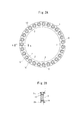
- FIG. 2A is a bottom view showing the overall structure of the spring assembly according to the first embodiment of the invention.
- FIG. 2B is also a cross-sectional view taken along the line AA.
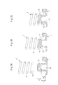
- 3A to 3C are enlarged cross-sectional views of the main part for explaining the configuration and operation of the support convex portion in the spring assembly according to the first embodiment of the present invention.
- FIGS. 4A to 4C are enlarged cross-sectional views of main parts for explaining the configuration and operation of the support recess in the spring assembly according to the second embodiment of the present invention.
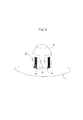
- FIG. 5 is a perspective view showing a modification of the first embodiment according to the present invention.
- FIG. 6 is a front sectional view showing an application example of the first embodiment according to the present invention.
- FIG. 7 is a front sectional view showing an application example of the second embodiment according to the present invention.
- FIG. 1 is an exploded perspective view showing an outline when the spring assembly according to the present invention is applied to a return spring structure of a multi-plate clutch piston in a clutch mechanism of an automatic transmission of an automobile.
- a spring assembly applied to a return spring structure of a multi-plate clutch piston in a clutch mechanism of an automatic transmission of an automobile includes a pair of resin substrates 1 having an annular shape and a plurality of coil springs 2 as components. The end winding portions at both ends of the coil spring 2 are fixed to the respective resin substrates 1 with a certain interval.
- FIGS. 3A to 3C are enlarged views showing the main part of the spring assembly.
- a plurality of support protrusions 10 are formed on the resin substrate 1.
- the plurality of support convex portions 10 are for fitting and fixing the end winding portions 2a of the coil spring 2, and are formed on the surface of the resin substrate 1 so as to protrude at regular intervals on the circumference. Yes.
- the support convex portion 10 has an outer peripheral surface formed in a circumferential surface shape, and is configured to fit and fix the end turn portion 2a of the coil spring 2 on the outer peripheral surface in the axial direction from the tip. As shown in an enlarged view in FIGS. 3A to 3C, the tip end portion (region) 11 of the support convex portion 10 is solid, and when the coil spring 2 is fitted, the end winding portion 2a of the coil spring 2 is formed. It has the rigidity that does not flex against the spring force inward in the radial direction.
- the region 12 from the base end of the support convex portion 10 to the tip end portion 11 is hollow due to the presence of the groove 13 extending in the axial direction from the back surface side of the resin substrate 1.
- An elastic deflection region 14 is formed in the region 12.
- the elastic deflection region 14 has a structure in which the peripheral wall is formed thin and is elastically bent by a radially inward spring force by the end winding portion 2a of the coil spring 2 when the coil spring 2 is fitted. ing. In this way, the region 14 can be formed with a simple structure in which the elastic deflection region 14 of the support convex portion 10 is hollow and its peripheral wall is thin.
- the elastic deflection region 14 may be all or part of the region 12 from the base end of the support convex portion 10 to the tip end portion 11.
- the end winding part 2a which is the first winding of each end, is reduced in diameter than the other intermediate winding part 2b.
- the inner diameter of the end winding portion 2a is smaller than the outer diameter of the support convex portion 10, and is elastically expanded and fitted into the tip portion 11 of the support convex portion 10.
- the inner diameter of the intermediate winding portion 2b of the coil spring 2 is made larger than the outer diameter of the support convex portion 10, and a gap is formed between the intermediate winding portion 2b and the support convex portion 10.
- the end winding portion 2 a of the coil spring 2 is disposed opposite to the tip portion 11 of the support convex portion 10 formed on the resin substrate 1, and faces the axial direction of the support convex portion 10. Then, the coil spring 2 is fitted. Then, as shown in FIG. 3B, the end winding portion 2a of the coil spring 2 comes into contact with the distal end portion 11 of the support convex portion 10 and is fitted while elastically expanding.
- the distal end portion 11 of the support convex portion 10 has a rigidity that does not bend even when it receives a radially inward spring force from the end winding portion 2 a of the coil spring 2.
- the end winding portion 2a reaches the elastic deflection region 14 of the support convex portion 10 as shown in FIG. 3C.
- the elastic bending region 14 receives a spring force inward in the radial direction from the end winding portion 2a of the coil spring 2, the elastic bending region 14 is elastically bent by the spring force and is contracted in the same direction.
- the leading end part 11 of the support convex part 10 serves as a stopper, and the removal is suppressed.
- the amount of bending (the amount of diameter reduction) of the elastic bending region 14 in the support convex portion 10 is small, and the constriction may not be recognized with the naked eye.
- the resin substrate 1 including the support protrusions 10 has a shape that eliminates unevenness in the horizontal direction on both the front surface and the back surface, and can be resin-molded only by a mold that opens and closes in the vertical direction. This eliminates the need for a slider mold that opens and closes in the lateral direction, which not only significantly reduces the mold cost, but also improves the workability.
- the outer peripheral surface of the mounting locking projection has irregularities, and when this is resin-molded, the main mold that opens and closes in the vertical direction and the horizontal It is necessary to combine a slider mold that opens and closes in the direction.
- FIGSecond Embodiment] 4A to 4C are enlarged views showing the main part of the spring assembly according to the second embodiment of the present invention.
- a plurality of support recesses 30 are formed in the resin substrate 1.
- the plurality of support recesses 30 are for fitting and fixing the end winding portions 2a of the coil spring 2, and are formed on the surface of the resin substrate 1 at regular intervals on the circumference.
- the support recess 30 has an inner peripheral surface formed in a circular shape, and is configured to fit and fix the end turn portion 2a of the coil spring 2 in the axial direction from the tip to the inner peripheral surface. .
- the opening edge 31 of the support recess 30 is surrounded by the base 1a of the resin substrate 1, so that when the coil spring 2 is fitted, It has rigidity that does not bend against a spring force radially outward by the end turn 2a.
- the region 32 from the bottom of the support recess 30 to the opening edge 31 is formed by a cylindrical wall extending to the back side of the resin substrate 1.
- An elastic deflection region 33 is formed in the region 32.
- the elastic bending region 33 has a structure in which a cylindrical wall is formed thin, and when the coil spring 2 is fitted, the elastic bending region 33 is elastically bent by a radially outward spring force by the end winding portion 2a of the coil spring 2. It has become. In this way, the region can be formed with a simple structure in which the elastic deflection region 33 of the support recess 30 is formed by a thin cylindrical wall.
- This elastic deflection region 33 may be all or part of the region 32 from the bottom of the support recess 30 to the opening edge 31.
- the coil spring 2 has an end winding portion 2a, which is the first winding at each end, having a larger diameter than the other intermediate winding portion 2b.
- the outer diameter of the end winding portion 2 a is larger than the inner diameter of the support recess 30, and is fitted into the opening edge 31 of the support recess 30 while being elastically reduced in diameter.
- the outer diameter of the intermediate winding part 2 b of the coil spring 2 is made smaller than the inner diameter of the support recess 30, and a gap is formed between the intermediate winding part 2 b and the support recess 30.
- the end winding portion 2 a of the coil spring 2 is disposed facing the opening edge 31 of the support recess 30 formed in the resin substrate 1, and toward the axial direction of the support recess 30.
- the coil spring 2 is fitted.
- the end winding portion 2a of the coil spring 2 comes into contact with the opening edge portion 31 of the support recess 30 and is fitted while being elastically reduced in diameter.
- the opening edge portion 31 of the support recessed portion 30 has a rigidity that does not bend even when receiving a spring force radially outward from the end winding portion 2 a of the coil spring 2.
- the end winding portion 2a reaches the elastic deflection region 33 of the support recess 30 as shown in FIG. 4C.
- the elastic bending region 33 receives a spring force radially outward from the end winding portion 2a of the coil spring 2, the elastic bending region 33 is elastically bent by the spring force and expands in the same direction.
- the opening edge part 31 of the support recessed part 30 serves as a stopper, and the removal is suppressed.
- the amount of bending (the amount of diameter reduction) of the elastic bending region 33 in the support recess 30 is small, and the swelling may not be recognized with the naked eye.
- the resin substrate 1 including the support recess 30 has a shape that eliminates unevenness in the horizontal direction on both the front surface and the back surface and can be resin-molded only by a mold that opens and closes in the vertical direction. This eliminates the need for a slider mold that opens and closes in the lateral direction, which not only significantly reduces the mold cost, but also improves the workability.
- the present invention is not limited to the above-described embodiments, and various modifications or applications are possible without departing from the spirit of the present invention.
- the inside of the support convex portion 10 is hollow, and a plurality of axial slits 41 are formed in the peripheral wall 40, thereby the peripheral wall 40.
- an elastic bending region 42 is formed on the inner surface of the coil spring 2 and the region 42 is elastically bent by a radially inward spring force by the end winding portion 2a of the coil spring 2.
- an elastic deflection region is formed in the cylindrical wall,
- the same region can also be configured to be elastically bent by a radially outward spring force by the end turn 2a of the coil spring 2.
- FIG. 6 shows an application example of the first embodiment described above, in which the height of the support projection 10 is extended to form a support wall 43 for preventing buckling of the intermediate winding 2b of the coil spring 2. Yes. It is preferable to provide a slight gap between the support wall 43 and the intermediate winding portion 2b of the coil spring 2 to eliminate the influence on the spring characteristics. When the coil spring 2 bends in the lateral direction, the coil spring 2 abuts against the support wall 43 to prevent buckling. When the strength of the elastic deflection region 14 is insufficient, the region 14 can be reinforced by providing an axial rib on the inner peripheral surface of the hollow portion within a range in which the region 14 can be elastically bent by the spring force of the coil spring 2. Good.
- FIG. 7 is an application example of the above-described second embodiment, in which the second coil spring 3 having a small diameter is inserted and arranged inside the coil spring 2 in which the end winding portion 2a is fixed to the support recess 30.
- the spring biasing force against the resin substrate 1 is increased.
- a projection 34 for positioning the second coil spring 3 is formed at the center of the inner bottom surface of the support recess 30 in the resin substrate 1.
- the second coil spring 3 is centered by loosely fitting both ends to the protrusions 34.
Landscapes
- Engineering & Computer Science (AREA)
- General Engineering & Computer Science (AREA)
- Mechanical Engineering (AREA)
- Springs (AREA)
Abstract
Description
なお、括弧内の符号は、特許文献1に記載された符号である。
前記樹脂製基板に、前記コイルばねの座巻部が嵌め込まれる支持凸部を有し、
当該支持凸部は、先端部が前記コイルばねの座巻部による径方向内向きのばね力に抗して撓まない剛性を有しており、基端から前記先端部に至るまでの領域に、前記コイルばねの座巻部による径方向内向きのばね力によって弾性的に撓む弾性撓み領域を形成した構成としてある。
よって、本発明によれば、熱かしめの作業を必要とすることなく、樹脂製基板に形成した支持凸部や支持凹部にコイルばねの座巻部を嵌め込むだけで、コイルばねの抜けを抑制することができる。
10:支持凸部、11:先端部、12:基端から先端部に至るまでの領域、13:溝、14:弾性撓み領域、
30:支持凹部、31:開口縁部、32:底部から開口縁部に至るまでの領域、33:弾性撓み領域、34:突起
40:周壁、41:スリット、42:弾性撓み領域、43:支持壁
自動車の自動変速機のクラッチ機構における多板クラッチピストンの戻しばね構造に適用されるばね組立体は、円環状をした一対の樹脂製基板1と、複数本のコイルばね2とを部品として、各コイルばね2の両端にある座巻部が、それぞれ各樹脂製基板1に一定の間隔を保って固定された構造となっている。
図2A、図2Bは本発明の第1実施形態に係るばね組立体の全体構造を示す図であり、図3A~図3Cは同ばね組立体の要部を拡大して示す図である。
本実施形態のばね組立体では、樹脂製基板1に複数の支持凸部10を形成してある。これら複数の支持凸部10は、コイルばね2の座巻部2aを嵌め込み固定するためのもので、樹脂製基板1の表面に、円周上に一定の間隔をおいて、突き出して形成されている。
図3A~図3Cに拡大して示すように、支持凸部10の先端部(領域)11は、中実となっており、コイルばね2が嵌め込まれる際に、コイルばね2の座巻部2aによる径方向内向きのばね力に抗して撓まない剛性を有している。
図3Aに示すように、樹脂製基板1に形成した支持凸部10の先端部11に対して、コイルばね2の座巻部2aを対向して配置し、支持凸部10の軸方向に向かってコイルばね2を嵌め込んでいく。そうすると、図3Bに示すように、コイルばね2の座巻部2aが、支持凸部10の先端部11に当接し、弾性的に拡開しながら嵌め込まれていく。支持凸部10の先端部11は、コイルばね2の座巻部2aから径方向内向きのばね力を受けても撓まない剛性を有している。
なお、支持凸部10における弾性撓み領域14の撓み量(縮径量)が僅かで、肉眼ではくびれが認識できないこともある。
比較対象として、特開2009-68590号公報に開示されたスプリングユニットでは、装着係止突部の外周面に凹凸があり、これを樹脂成形する場合は、縦方向に開閉する主金型と横方向へ開閉するスライダ金型を組み合わせる必要がある。
図4A~図4Cは本発明の第2実施形態に係るばね組立体の要部を拡大して示す図である。
本実施形態のばね組立体では、樹脂製基板1に複数の支持凹部30を形成してある。これら複数の支持凹部30は、コイルばね2の座巻部2aを嵌め込み固定するためのもので、樹脂製基板1の表面に、円周上に一定の間隔をおいて形成されている。
図4A~図4Cに拡大して示すように、支持凹部30の開口縁部31は、樹脂製基板1における基部1aに囲まれているため、コイルばね2が嵌め込まれる際に、コイルばね2の座巻部2aによる径方向外向きのばね力に抗して撓まない剛性を有している。
図4Aに示すように、樹脂製基板1に形成した支持凹部30の開口縁部31に対して、コイルばね2の座巻部2aを対向して配置し、支持凹部30の軸方向に向かってコイルばね2を嵌め込んでいく。そうすると、図4Bに示すように、コイルばね2の座巻部2aが、支持凹部30の開口縁部31に当接し、弾性的に縮径しながら嵌め込まれていく。支持凹部30の開口縁部31は、コイルばね2の座巻部2aから径方向外向きのばね力を受けても撓まない剛性を有している。
なお、支持凹部30における弾性撓み領域33の撓み量(縮径量)が僅かで、肉眼では膨らみが認識できないこともある。
本発明は、上述した実施形態に限定されるものではなく、要旨を逸脱しない範囲で、種々の変形又は応用が可能である。
例えば、上述した第1実施形態の変形例として、図5に示すように、支持凸部10の内部を中空とし、かつ周壁40に軸方向のスリット41を複数本形成することで、当該周壁40に弾性撓み領域42を形成し、同領域42をコイルばね2の座巻部2aによる径方向内向きのばね力によって弾性的に撓む構造とすることもできる。
支持壁43とコイルばね2の中間巻部2bとの間には僅かながら隙間を設けてばね特性への影響を無くすことが好ましい。そして、コイルばね2が横方向に撓んだとき、支持壁43に当接して座屈が防止される。
弾性撓み領域14の強度が不足するときは、同領域14がコイルばね2のばね力によって弾性的に撓み可能な範囲で、中空部内周面に軸方向のリブを設ける等して補強してもよい。
Claims (8)
- 樹脂製基板にコイルばねの座巻部が固定されたばね組立体であって、
前記樹脂製基板に、前記コイルばねの座巻部が嵌め込まれる支持凸部を有し、
当該支持凸部は、先端部が前記コイルばねの座巻部による径方向内向きのばね力に抗して撓まない剛性を有しており、基端から前記先端部に至るまでの領域に、前記コイルばねの座巻部による径方向内向きのばね力により弾性的に撓む弾性撓み領域を形成したばね組立体。 - 支持凸部は、少なくとも前記弾性撓み領域の内部が中空となっており、且つ当該領域の周壁は薄肉に形成することで、前記コイルばねの座巻部による径方向内向きのばね力により弾性的に撓む構造としてある請求項1のばね組立体。
- 前記支持凸部は、少なくとも前記弾性撓み領域の内部が中空となっており、且つ当該領域の周壁に軸方向のスリットを複数本形成することで、前記コイルばねの座巻部による径方向内向きのばね力により弾性的に撓む構造としてある請求項1のばね組立体。
- 前記コイルばねは、座巻部が中間巻部よりも縮径してあり、前記支持凸部の先端部に対して弾性的に拡開して嵌め込まれる構造となっている請求項1のばね組立体。
- 樹脂製基板にコイルばねの座巻部が固定されたばね組立体であって、
前記樹脂製基板に、前記コイルばねの座巻部が嵌め込まれる支持凹部を有し、
当該支持凹部は、開口縁部が前記コイルばねの座巻部による径方向外向きのばね力に抗して撓まない剛性を有しており、底部から前記開口縁部に至るまでの領域に、前記コイルばねの座巻部による径方向外向きのばね力により弾性的に撓む弾性撓み領域を形成したばね組立体。 - 支持凹部は、少なくとも前記弾性撓み領域を薄肉の円筒壁により形成することで、前記コイルばねの座巻部による径方向外向きのばね力により弾性的に撓む構造としてある請求項5のばね組立体。
- 前記支持凸部は、少なくとも前記弾性撓み領域が円筒壁で形成されており、且つ当該円筒壁に軸方向のスリットを複数本形成することで、前記コイルばねの座巻部による径方向内向きのばね力により弾性的に撓む構造としてある請求項5のばね組立体。
- 前記コイルばねは、座巻部が中間巻部よりも拡径してあり、前記支持凹部の開口縁部に対して弾性的に縮径して嵌め込まれる構造となっている請求項5のばね組立体。
Priority Applications (4)
| Application Number | Priority Date | Filing Date | Title |
|---|---|---|---|
| CN201280011796.XA CN103403386B (zh) | 2011-03-04 | 2012-02-29 | 弹簧组装体 |
| DE112012001101T DE112012001101T5 (de) | 2011-03-04 | 2012-02-29 | Federanordnung |
| US14/002,330 US9416836B2 (en) | 2011-03-04 | 2012-02-29 | Spring assembly |
| JP2013503467A JP5697277B2 (ja) | 2011-03-04 | 2012-02-29 | ばね組立体 |
Applications Claiming Priority (2)
| Application Number | Priority Date | Filing Date | Title |
|---|---|---|---|
| JP2011-047522 | 2011-03-04 | ||
| JP2011047522 | 2011-03-04 |
Publications (1)
| Publication Number | Publication Date |
|---|---|
| WO2012121072A1 true WO2012121072A1 (ja) | 2012-09-13 |
Family
ID=46798040
Family Applications (1)
| Application Number | Title | Priority Date | Filing Date |
|---|---|---|---|
| PCT/JP2012/055030 Ceased WO2012121072A1 (ja) | 2011-03-04 | 2012-02-29 | ばね組立体 |
Country Status (5)
| Country | Link |
|---|---|
| US (1) | US9416836B2 (ja) |
| JP (1) | JP5697277B2 (ja) |
| CN (1) | CN103403386B (ja) |
| DE (1) | DE112012001101T5 (ja) |
| WO (1) | WO2012121072A1 (ja) |
Cited By (7)
| Publication number | Priority date | Publication date | Assignee | Title |
|---|---|---|---|---|
| CN104033705A (zh) * | 2014-06-04 | 2014-09-10 | 成都来宝石油设备有限公司 | 电动阀门的稳定调试支撑装置 |
| WO2014208481A1 (ja) * | 2013-06-26 | 2014-12-31 | 株式会社イマイ | スプリングユニット |
| JP2016035289A (ja) * | 2014-08-01 | 2016-03-17 | 株式会社ジェイテクト | ボールねじ装置 |
| WO2016157881A1 (ja) * | 2015-03-27 | 2016-10-06 | 日本発條株式会社 | ばねシート部材及びばね組立て体 |
| JP2019116948A (ja) * | 2017-12-27 | 2019-07-18 | 株式会社パイオラックス | バネ組立体 |
| WO2020194590A1 (ja) * | 2019-03-27 | 2020-10-01 | 三菱電機株式会社 | 緩衝器のばね支持台、及びエレベータ緩衝器 |
| CN112648303A (zh) * | 2019-10-09 | 2021-04-13 | 法雷奥离合器公司 | 紧凑湿式双离合器机构 |
Families Citing this family (14)
| Publication number | Priority date | Publication date | Assignee | Title |
|---|---|---|---|---|
| DE102013226047B4 (de) * | 2013-12-16 | 2017-08-03 | Volkswagen Aktiengesellschaft | Stellanordnung zur Rückstellung oder zur Betätigung eines Betätigungskolbens einer Kupplung |
| GB2523141C (en) * | 2014-02-14 | 2020-12-02 | Newbridge Brake Ltd | Disc brake caliper |
| DE102014102515A1 (de) * | 2014-02-26 | 2015-08-27 | Getrag Getriebe- Und Zahnradfabrik Hermann Hagenmeyer Gmbh & Cie Kg | Federpaket, Kupplung und Kupplungsherstellungsverfahren |
| CN104033713B (zh) * | 2014-06-04 | 2016-03-02 | 成都来宝石油设备有限公司 | 可调节高度的电动阀门调试支撑装置 |
| DE102014212701A1 (de) * | 2014-07-01 | 2016-01-07 | Dichtungstechnik G. Bruss Gmbh & Co. Kg | Vorrichtung zur Betätigung einer Kupplung in einem hydraulischen System und Verfahren zur Herstellung einer solchen Vorrichtung |
| CN104295648A (zh) * | 2014-09-26 | 2015-01-21 | 无锡市天力五金弹簧厂 | 一种带有固定装置的弹簧 |
| DE102016207019B4 (de) * | 2016-04-26 | 2024-09-12 | Schaeffler Technologies AG & Co. KG | Kupplungseinrichtung |
| US10267368B2 (en) * | 2016-12-06 | 2019-04-23 | GM Global Technology Operations LLC | Spring pack assembly for a torque transmitting device |
| US10233980B2 (en) * | 2016-12-13 | 2019-03-19 | GM Global Technology Operations LLC | Spring pack assembly for a torque transmitting device |
| JP2019002893A (ja) * | 2017-06-20 | 2019-01-10 | 矢崎総業株式会社 | 温度センサ |
| US11566681B2 (en) | 2018-12-17 | 2023-01-31 | Raytheon Canada Limited | Coaxial spring damper device and system |
| FR3101927B1 (fr) * | 2019-10-09 | 2021-10-08 | Valeo Embrayages | « Dispositif de rappel élastique commun pour double embrayage humide et double embrayage humide de type compact comprenant un tel dispositif de rappel élastique » |
| CN115163693B (zh) * | 2022-07-25 | 2023-11-21 | 盐城工学院 | 一种稳定性高的感应弹簧 |
| US12565915B2 (en) * | 2024-02-16 | 2026-03-03 | Goerend Transmissions, Inc. | Piston spring return assembly for automatic transmission |
Citations (3)
| Publication number | Priority date | Publication date | Assignee | Title |
|---|---|---|---|---|
| JPS59191439U (ja) * | 1983-06-07 | 1984-12-19 | 中央発條株式会社 | 座板付圧縮コイルばね |
| JP2007024278A (ja) * | 2005-07-21 | 2007-02-01 | Suncall Corp | ダンパースプリング及びシート部材 |
| JP2007292271A (ja) * | 2006-04-27 | 2007-11-08 | Togo Seisakusho Corp | ばねシート部材及びばね組立て体 |
Family Cites Families (27)
| Publication number | Priority date | Publication date | Assignee | Title |
|---|---|---|---|---|
| US1878128A (en) * | 1927-11-10 | 1932-09-20 | Packard Motor Car Co | Valve spring |
| US2278324A (en) * | 1940-04-27 | 1942-03-31 | Karl J Kollmann | Coupling |
| US2412712A (en) * | 1942-07-27 | 1946-12-17 | Line Material Co | Method of assembling fuse links |
| US2700788A (en) * | 1954-03-22 | 1955-02-01 | Walter L Hennelly | Laterally resiliently displaceable stop for relatively movable elements |
| FR1391845A (fr) * | 1964-01-17 | 1965-03-12 | Metallurg De Saint Urbain Atel | Ressort hélicoïdal perfectionné |
| US3531069A (en) * | 1968-11-27 | 1970-09-29 | Gen Electric | Vibration mount for compressors and the like |
| JPS58150012A (ja) * | 1982-03-02 | 1983-09-06 | Nissan Motor Co Ltd | 内燃機関のバルブ装置 |
| JPS59191439A (ja) | 1983-04-15 | 1984-10-30 | 松下電器産業株式会社 | 太陽電池電源装置 |
| JPS61112139U (ja) * | 1984-12-26 | 1986-07-16 | ||
| US4830348A (en) * | 1987-01-08 | 1989-05-16 | Perfection Spring & Stamping Corp. | Noise suppressing device for coil springs |
| JPH01307530A (ja) * | 1988-06-03 | 1989-12-12 | Nhk Spring Co Ltd | スプリング組立体 |
| JPH0320131A (ja) * | 1989-06-16 | 1991-01-29 | Nhk Spring Co Ltd | ばね装置 |
| EP0539955B1 (en) * | 1991-10-30 | 1998-02-18 | Togo Seisakusho Corporation | Spring assembly for automatic transmission of automotive vehicle and the like |
| JP3384814B2 (ja) | 1991-10-30 | 2003-03-10 | 株式会社東郷製作所 | スプリング組立体 |
| JP3769854B2 (ja) * | 1997-01-20 | 2006-04-26 | 日産自動車株式会社 | サスペンションスプリングアッパマウント構造 |
| JP2002295558A (ja) * | 2001-03-30 | 2002-10-09 | Tokai Rubber Ind Ltd | スプリングシートラバー |
| SG157949A1 (en) | 2004-07-28 | 2010-01-29 | Panasonic Refrigeration Device | System for reducing compressor noise and suspension spring and snubber arrangement therefor |
| US8616538B2 (en) * | 2004-10-20 | 2013-12-31 | Basf Corporation | Spring seat assembly |
| US7370855B2 (en) * | 2005-01-25 | 2008-05-13 | Youd Jason B | Spring damper |
| US20080211156A1 (en) * | 2005-11-09 | 2008-09-04 | Check Ronald N | Spring damper |
| JP4636009B2 (ja) * | 2006-02-21 | 2011-02-23 | 東海ゴム工業株式会社 | 車両用サスペンションのスプリングシート |
| US8052129B2 (en) * | 2006-04-25 | 2011-11-08 | Youd Jason B | Steel spring damper |
| JP2009068590A (ja) | 2007-09-12 | 2009-04-02 | Togo Seisakusho Corp | スプリングユニット |
| JP2010007772A (ja) * | 2008-06-27 | 2010-01-14 | Tokai Rubber Ind Ltd | スプリングシート |
| CN201439809U (zh) * | 2009-05-27 | 2010-04-21 | 上汽通用五菱汽车股份有限公司 | 塔形弹簧装置 |
| JP5448184B2 (ja) * | 2009-06-18 | 2014-03-19 | 株式会社パイオラックス | ばね組立体とその製造方法 |
| US20110303046A1 (en) * | 2010-06-15 | 2011-12-15 | Gentry Nicholas K | Damper Element for Springs and Vehicle Pedal Assembly Incorporating the Same |
-
2012
- 2012-02-29 US US14/002,330 patent/US9416836B2/en not_active Expired - Fee Related
- 2012-02-29 JP JP2013503467A patent/JP5697277B2/ja not_active Expired - Fee Related
- 2012-02-29 WO PCT/JP2012/055030 patent/WO2012121072A1/ja not_active Ceased
- 2012-02-29 DE DE112012001101T patent/DE112012001101T5/de not_active Withdrawn
- 2012-02-29 CN CN201280011796.XA patent/CN103403386B/zh not_active Expired - Fee Related
Patent Citations (3)
| Publication number | Priority date | Publication date | Assignee | Title |
|---|---|---|---|---|
| JPS59191439U (ja) * | 1983-06-07 | 1984-12-19 | 中央発條株式会社 | 座板付圧縮コイルばね |
| JP2007024278A (ja) * | 2005-07-21 | 2007-02-01 | Suncall Corp | ダンパースプリング及びシート部材 |
| JP2007292271A (ja) * | 2006-04-27 | 2007-11-08 | Togo Seisakusho Corp | ばねシート部材及びばね組立て体 |
Cited By (12)
| Publication number | Priority date | Publication date | Assignee | Title |
|---|---|---|---|---|
| WO2014208481A1 (ja) * | 2013-06-26 | 2014-12-31 | 株式会社イマイ | スプリングユニット |
| CN104033705A (zh) * | 2014-06-04 | 2014-09-10 | 成都来宝石油设备有限公司 | 电动阀门的稳定调试支撑装置 |
| JP2016035289A (ja) * | 2014-08-01 | 2016-03-17 | 株式会社ジェイテクト | ボールねじ装置 |
| WO2016157881A1 (ja) * | 2015-03-27 | 2016-10-06 | 日本発條株式会社 | ばねシート部材及びばね組立て体 |
| JPWO2016157881A1 (ja) * | 2015-03-27 | 2018-01-18 | 日本発條株式会社 | ばねシート部材及びばね組立て体 |
| JP2019116948A (ja) * | 2017-12-27 | 2019-07-18 | 株式会社パイオラックス | バネ組立体 |
| JP7009204B2 (ja) | 2017-12-27 | 2022-01-25 | 株式会社パイオラックス | バネ組立体 |
| WO2020194590A1 (ja) * | 2019-03-27 | 2020-10-01 | 三菱電機株式会社 | 緩衝器のばね支持台、及びエレベータ緩衝器 |
| JPWO2020194590A1 (ja) * | 2019-03-27 | 2021-10-14 | 三菱電機株式会社 | 緩衝器のばね支持台、及びエレベータ緩衝器 |
| JP7134335B2 (ja) | 2019-03-27 | 2022-09-09 | 三菱電機株式会社 | 緩衝器のばね支持台、及びエレベータ緩衝器 |
| CN112648303A (zh) * | 2019-10-09 | 2021-04-13 | 法雷奥离合器公司 | 紧凑湿式双离合器机构 |
| CN112648303B (zh) * | 2019-10-09 | 2024-06-04 | 法雷奥离合器公司 | 紧凑湿式双离合器机构 |
Also Published As
| Publication number | Publication date |
|---|---|
| US9416836B2 (en) | 2016-08-16 |
| DE112012001101T5 (de) | 2013-12-24 |
| US20130334750A1 (en) | 2013-12-19 |
| CN103403386B (zh) | 2016-08-17 |
| CN103403386A (zh) | 2013-11-20 |
| JP5697277B2 (ja) | 2015-04-08 |
| JPWO2012121072A1 (ja) | 2014-07-17 |
Similar Documents
| Publication | Publication Date | Title |
|---|---|---|
| JP5697277B2 (ja) | ばね組立体 | |
| US9273743B2 (en) | Spring assembly and manufacturing method therefor | |
| CN103890439B (zh) | 弹簧座构件和装备有该构件的弹簧组件 | |
| CN102959272B (zh) | 止动帽 | |
| EP3705736B1 (en) | Fixation structure | |
| JP4626661B2 (ja) | 固定部材 | |
| JPWO2018143071A1 (ja) | バネ組立体 | |
| JP2006516320A (ja) | スナップリングを固定するための構成 | |
| JP4699273B2 (ja) | ばねシート部材及びばね組立て体 | |
| JP7009204B2 (ja) | バネ組立体 | |
| CN105074269A (zh) | 转矩杆 | |
| JPWO2013171986A1 (ja) | ばね装置 | |
| JP6934389B2 (ja) | バネ組立体 | |
| JP2018138816A (ja) | 直線運動装置 | |
| JP2019015321A (ja) | バネ組立体 | |
| KR102005152B1 (ko) | 듀얼 매스 플라이휠 | |
| JP7191483B2 (ja) | 留め具 | |
| JP7288972B2 (ja) | ばね組立体 | |
| WO2015125618A1 (ja) | ワンウェイクラッチ | |
| JP6227897B2 (ja) | 留め具 | |
| JP2012026528A (ja) | フリクションダンパ | |
| EP3153733A1 (en) | Clutch bearing device with rear plate | |
| JP2017003111A (ja) | 止め輪保持構造 | |
| JPH08270686A (ja) | 一方向クラッチ用の外側保持器 |
Legal Events
| Date | Code | Title | Description |
|---|---|---|---|
| 121 | Ep: the epo has been informed by wipo that ep was designated in this application |
Ref document number: 12755208 Country of ref document: EP Kind code of ref document: A1 |
|
| DPE1 | Request for preliminary examination filed after expiration of 19th month from priority date (pct application filed from 20040101) | ||
| ENP | Entry into the national phase |
Ref document number: 2013503467 Country of ref document: JP Kind code of ref document: A |
|
| WWE | Wipo information: entry into national phase |
Ref document number: 14002330 Country of ref document: US |
|
| WWE | Wipo information: entry into national phase |
Ref document number: 112012001101 Country of ref document: DE Ref document number: 1120120011015 Country of ref document: DE |
|
| 122 | Ep: pct application non-entry in european phase |
Ref document number: 12755208 Country of ref document: EP Kind code of ref document: A1 |