WO2012120808A1 - ロータリ圧縮機 - Google Patents
ロータリ圧縮機 Download PDFInfo
- Publication number
- WO2012120808A1 WO2012120808A1 PCT/JP2012/001235 JP2012001235W WO2012120808A1 WO 2012120808 A1 WO2012120808 A1 WO 2012120808A1 JP 2012001235 W JP2012001235 W JP 2012001235W WO 2012120808 A1 WO2012120808 A1 WO 2012120808A1
- Authority
- WO
- WIPO (PCT)
- Prior art keywords
- chamber
- suction
- compression mechanism
- volume
- back pressure
- Prior art date
Links
Images


Classifications
-
- F—MECHANICAL ENGINEERING; LIGHTING; HEATING; WEAPONS; BLASTING
- F04—POSITIVE - DISPLACEMENT MACHINES FOR LIQUIDS; PUMPS FOR LIQUIDS OR ELASTIC FLUIDS
- F04C—ROTARY-PISTON, OR OSCILLATING-PISTON, POSITIVE-DISPLACEMENT MACHINES FOR LIQUIDS; ROTARY-PISTON, OR OSCILLATING-PISTON, POSITIVE-DISPLACEMENT PUMPS
- F04C28/00—Control of, monitoring of, or safety arrangements for, pumps or pumping installations specially adapted for elastic fluids
- F04C28/24—Control of, monitoring of, or safety arrangements for, pumps or pumping installations specially adapted for elastic fluids characterised by using valves controlling pressure or flow rate, e.g. discharge valves or unloading valves
- F04C28/26—Control of, monitoring of, or safety arrangements for, pumps or pumping installations specially adapted for elastic fluids characterised by using valves controlling pressure or flow rate, e.g. discharge valves or unloading valves using bypass channels
-
- F—MECHANICAL ENGINEERING; LIGHTING; HEATING; WEAPONS; BLASTING
- F04—POSITIVE - DISPLACEMENT MACHINES FOR LIQUIDS; PUMPS FOR LIQUIDS OR ELASTIC FLUIDS
- F04C—ROTARY-PISTON, OR OSCILLATING-PISTON, POSITIVE-DISPLACEMENT MACHINES FOR LIQUIDS; ROTARY-PISTON, OR OSCILLATING-PISTON, POSITIVE-DISPLACEMENT PUMPS
- F04C28/00—Control of, monitoring of, or safety arrangements for, pumps or pumping installations specially adapted for elastic fluids
- F04C28/08—Control of, monitoring of, or safety arrangements for, pumps or pumping installations specially adapted for elastic fluids characterised by varying the rotational speed
-
- F—MECHANICAL ENGINEERING; LIGHTING; HEATING; WEAPONS; BLASTING
- F04—POSITIVE - DISPLACEMENT MACHINES FOR LIQUIDS; PUMPS FOR LIQUIDS OR ELASTIC FLUIDS
- F04C—ROTARY-PISTON, OR OSCILLATING-PISTON, POSITIVE-DISPLACEMENT MACHINES FOR LIQUIDS; ROTARY-PISTON, OR OSCILLATING-PISTON, POSITIVE-DISPLACEMENT PUMPS
- F04C18/00—Rotary-piston pumps specially adapted for elastic fluids
- F04C18/30—Rotary-piston pumps specially adapted for elastic fluids having the characteristics covered by two or more of groups F04C18/02, F04C18/08, F04C18/22, F04C18/24, F04C18/48, or having the characteristics covered by one of these groups together with some other type of movement between co-operating members
- F04C18/34—Rotary-piston pumps specially adapted for elastic fluids having the characteristics covered by two or more of groups F04C18/02, F04C18/08, F04C18/22, F04C18/24, F04C18/48, or having the characteristics covered by one of these groups together with some other type of movement between co-operating members having the movement defined in group F04C18/08 or F04C18/22 and relative reciprocation between the co-operating members
- F04C18/356—Rotary-piston pumps specially adapted for elastic fluids having the characteristics covered by two or more of groups F04C18/02, F04C18/08, F04C18/22, F04C18/24, F04C18/48, or having the characteristics covered by one of these groups together with some other type of movement between co-operating members having the movement defined in group F04C18/08 or F04C18/22 and relative reciprocation between the co-operating members with vanes reciprocating with respect to the outer member
- F04C18/3562—Rotary-piston pumps specially adapted for elastic fluids having the characteristics covered by two or more of groups F04C18/02, F04C18/08, F04C18/22, F04C18/24, F04C18/48, or having the characteristics covered by one of these groups together with some other type of movement between co-operating members having the movement defined in group F04C18/08 or F04C18/22 and relative reciprocation between the co-operating members with vanes reciprocating with respect to the outer member the inner and outer member being in contact along one line or continuous surfaces substantially parallel to the axis of rotation
- F04C18/3564—Rotary-piston pumps specially adapted for elastic fluids having the characteristics covered by two or more of groups F04C18/02, F04C18/08, F04C18/22, F04C18/24, F04C18/48, or having the characteristics covered by one of these groups together with some other type of movement between co-operating members having the movement defined in group F04C18/08 or F04C18/22 and relative reciprocation between the co-operating members with vanes reciprocating with respect to the outer member the inner and outer member being in contact along one line or continuous surfaces substantially parallel to the axis of rotation the surfaces of the inner and outer member, forming the working space, being surfaces of revolution
-
- F—MECHANICAL ENGINEERING; LIGHTING; HEATING; WEAPONS; BLASTING
- F04—POSITIVE - DISPLACEMENT MACHINES FOR LIQUIDS; PUMPS FOR LIQUIDS OR ELASTIC FLUIDS
- F04C—ROTARY-PISTON, OR OSCILLATING-PISTON, POSITIVE-DISPLACEMENT MACHINES FOR LIQUIDS; ROTARY-PISTON, OR OSCILLATING-PISTON, POSITIVE-DISPLACEMENT PUMPS
- F04C2240/00—Components
- F04C2240/40—Electric motor
- F04C2240/403—Electric motor with inverter for speed control
-
- F—MECHANICAL ENGINEERING; LIGHTING; HEATING; WEAPONS; BLASTING
- F04—POSITIVE - DISPLACEMENT MACHINES FOR LIQUIDS; PUMPS FOR LIQUIDS OR ELASTIC FLUIDS
- F04C—ROTARY-PISTON, OR OSCILLATING-PISTON, POSITIVE-DISPLACEMENT MACHINES FOR LIQUIDS; ROTARY-PISTON, OR OSCILLATING-PISTON, POSITIVE-DISPLACEMENT PUMPS
- F04C23/00—Combinations of two or more pumps, each being of rotary-piston or oscillating-piston type, specially adapted for elastic fluids; Pumping installations specially adapted for elastic fluids; Multi-stage pumps specially adapted for elastic fluids
- F04C23/001—Combinations of two or more pumps, each being of rotary-piston or oscillating-piston type, specially adapted for elastic fluids; Pumping installations specially adapted for elastic fluids; Multi-stage pumps specially adapted for elastic fluids of similar working principle
-
- F—MECHANICAL ENGINEERING; LIGHTING; HEATING; WEAPONS; BLASTING
- F04—POSITIVE - DISPLACEMENT MACHINES FOR LIQUIDS; PUMPS FOR LIQUIDS OR ELASTIC FLUIDS
- F04C—ROTARY-PISTON, OR OSCILLATING-PISTON, POSITIVE-DISPLACEMENT MACHINES FOR LIQUIDS; ROTARY-PISTON, OR OSCILLATING-PISTON, POSITIVE-DISPLACEMENT PUMPS
- F04C23/00—Combinations of two or more pumps, each being of rotary-piston or oscillating-piston type, specially adapted for elastic fluids; Pumping installations specially adapted for elastic fluids; Multi-stage pumps specially adapted for elastic fluids
- F04C23/008—Hermetic pumps
Definitions
- the present invention relates to a rotary compressor.
- Compressor motors are usually controlled by an inverter and a microcomputer. If the number of rotations of the motor is lowered, the refrigeration cycle apparatus using the compressor can be operated with a sufficiently lower capacity than the rating. Patent Document 1 further provides one technique for operating the refrigeration cycle apparatus with such a low capacity that cannot be realized by inverter control.
- FIG. 16 is a configuration diagram of the air conditioner described in Patent Document 1.
- the compressor 715, the four-way valve 717, the indoor heat exchanger 718, the pressure reducing device 719, and the outdoor heat exchanger 720 constitute a refrigeration cycle.
- the cylinder of the compressor 715 is provided with an intermediate discharge port that opens from the start to the middle of the compression stroke.
- the intermediate discharge port is connected to the suction path of the compressor 715 by a bypass path 723.
- the bypass 723 is provided with a flow control device 721 and an electromagnetic on-off valve 722.
- the electromagnetic on-off valve 722 is opened only during operation at a low set frequency. Thereby, the driving
- the shortcut to increase the efficiency of the refrigeration cycle apparatus is to increase the efficiency of the compressor.
- the efficiency of the compressor is highly dependent on the efficiency of the motor used. Many motors are designed to exhibit the highest efficiency at a rotational speed in the vicinity of a rated rotational speed (for example, 60 Hz). Therefore, if the motor is driven at an extremely low number of revolutions, improvement in the efficiency of the compressor cannot be expected.
- a variable capacity mechanism such as a bypass path
- the present invention provides a rotary compressor that can exhibit high efficiency even when low capacity is required (when the load is small), and also during normal operation (when the load is large).
- An object of the present invention is to provide a rotary compressor that can exhibit high efficiency.
- the present invention provides a cylinder, a piston disposed in the cylinder so that a working chamber is formed between the outer peripheral surface of the cylinder and the inner peripheral surface of the cylinder, and the working chamber is compressed with the suction chamber.
- a vane that is partitioned into a discharge chamber, a suction port that allows the working fluid to be compressed to flow into the suction chamber, a discharge port that allows the compressed working fluid to flow out of the compression-discharge chamber, and allows the working fluid to escape from the compression-discharge chamber
- a compression mechanism including a return port, a shaft having an eccentric portion that fits into the piston, a motor that rotates the shaft, a suction path that guides the working fluid to the suction port, and the feedback port.
- a back pressure chamber a reed valve type check valve which is disposed in the back pressure chamber and opens and closes the return port by elastic deformation, and a working fluid from the back pressure chamber
- a return path, and a return path provided in the return path when the suction volume of the compression mechanism should be relatively small, allow the working fluid to flow through the feedback path, and when the suction volume should be relatively large
- a volume change valve that increases the pressure in the back pressure chamber by prohibiting the flow of the working fluid through the return path, an inverter that drives the motor, and a decrease in the suction volume is compensated by an increase in the rotation speed of the motor.
- a rotary compressor including the volume change valve and a control unit that controls the inverter is provided.
- the volume change valve can be operated with a relatively small suction volume.
- the volume change valve and the inverter are controlled so as to compensate for the decrease in the suction volume by the increase in the rotation speed of the motor. That is, instead of driving the motor at a low rotational speed, the suction volume is reduced. Therefore, it is possible to provide a rotary compressor that can exhibit high efficiency even when the load is small. Further, by using a reed valve type check valve, the return port can be opened and closed with a simple configuration.
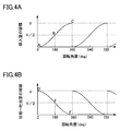
- FIG. 4A is a graph showing the relationship between the rotation angle of the shaft and the volume of the suction chamber
- FIG. 4B is a graph showing the relationship between the rotation angle of the shaft and the volume of the compression-discharge chamber.
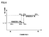
- Control flow chart of variable displacement mechanism (open / close valve) and inverter A graph showing the relationship between the capacity of the rotary compressor, the suction volume of the compression mechanism, the state of the on-off valve, and the rotational speed of the motor
- Another control flowchart of variable displacement mechanism (open / close valve) and inverter Graph showing the relationship between rotary compressor capacity and rotary compressor efficiency 9A is a graph showing the relationship between the rotation angle of the shaft and the flow rate of the refrigerant in the suction path
- FIG. 9B is a graph showing the relationship between the rotation angle of the shaft and the flow rate of the refrigerant in the return path
- FIG. 9C shows the rotation angle of the shaft.
- FIG. 10 Graph showing the relationship with the flow rate of refrigerant in the inlet pipe of the accumulator
- Cross-sectional view along line XI-XI in Fig. 10 Cross-sectional view showing a modified example of the position of the return port
- Configuration diagram of a refrigeration cycle apparatus using the rotary compressor of the present embodiment Configuration diagram of conventional air conditioner
- the rotary compressor 100 of this embodiment includes a compressor body 40, an accumulator 12, a suction path 14, a discharge path 11, a return path 16, an inverter 42, and a control unit 44.
- the compressor main body 40 includes a sealed container 1, a motor 2, a compression mechanism 3, and a shaft 4.
- the compression mechanism 3 is disposed below the sealed container 1.
- the motor 2 is disposed above the compression mechanism 3 in the sealed container 1.
- the shaft 4 extends in the vertical direction and connects the compression mechanism 3 and the motor 2.
- a terminal 21 for supplying electric power to the motor 2 is provided on the top of the sealed container 1.
- An oil reservoir 22 for holding lubricating oil is formed at the bottom of the sealed container 1.
- the compressor body 40 has a so-called hermetic compressor structure.
- the motor 2 includes a stator 2a and a rotor 2b.
- the stator 2 a is fixed to the inner peripheral surface of the sealed container 1.
- the rotor 2 b is fixed to the shaft 4 and rotates together with the shaft 4.
- a motor capable of changing the rotational speed such as IPMSM (Interior Permanent Magnet Synchronous Mortar) and SPMSM (Surface Permanent Magnet Synchronous Mortar), can be used.
- the motor 2 is driven by the inverter 42.
- the control unit 44 controls the inverter 42 to adjust the rotational speed of the motor 2, that is, the rotational speed of the rotary compressor 100.
- a DSP Digital Signal Processor
- a / D conversion circuit an input / output circuit, an arithmetic circuit, a storage device, and the like can be used.
- the discharge path 11, the suction path 14, and the return path 16 are each configured by piping.
- the discharge path 11 passes through the upper part of the sealed container 1 and opens into the internal space 28 of the sealed container 1.
- the discharge path 11 plays a role of guiding a compressed working fluid (typically a refrigerant) to the outside of the compressor body 40.
- the suction path 14 extends from the accumulator 12 to the compression mechanism 3 and penetrates the trunk of the sealed container 1.
- the suction path 14 plays a role of guiding the refrigerant to be compressed from the accumulator 12 to the suction port 3 a of the compression mechanism 3.
- the return path 16 extends from the compression mechanism 3 to the accumulator 12 and penetrates the trunk of the sealed container 1.
- the return path 16 plays a role of returning the refrigerant discharged from the working chamber 53 of the compression mechanism 3 without being compressed from the back pressure chamber 18 described later to the suction path 14.
- the accumulator 12 includes a storage container 12a and an introduction pipe 12b.
- the storage container 12a has an internal space that can hold a liquid refrigerant and a gas refrigerant.
- the introduction pipe 12b penetrates the upper part of the storage container 12a and opens into the internal space of the storage container 12a.
- the suction path 14 and the return path 16 are connected to the accumulator 12 so as to penetrate the bottom of the storage container 12a.
- the suction path 14 and the return path 16 extend upward from the bottom of the storage container 12a, and the upstream end of the suction path 14 and the downstream end of the return path 16 open into the internal space of the storage container 12a at a certain height position. Yes.
- the return path 16 communicates with the suction path 14 via the internal space of the accumulator 12.
- another member such as a baffle may be provided inside the storage container 12a in order to reliably prevent the liquid refrigerant from proceeding directly from the introduction pipe 12b to the suction path 14.
- the downstream end of the return path 16 may be connected to the introduction pipe 12b.
- the compression mechanism 3 is a positive displacement fluid mechanism, and is moved by the motor 2 to suck the refrigerant from the suction port 3a, compress the refrigerant, and discharge it from the discharge port 3b.
- the compression mechanism 3 includes a cylinder 51, a piston 52, a vane 54, a spring 55, an upper closing member 61, and a lower closing member 62.
- the cylinder 51 is fixed to the inner peripheral surface of the sealed container 1. Inside the cylinder 51, a piston 52 fitted to the eccentric portion 4 a of the shaft 4 is disposed so that a working chamber 53 is formed between the outer peripheral surface of the cylinder 51 and the inner peripheral surface of the cylinder 51.
- a vane groove 56 is formed in the cylinder 51.
- the vane groove 56 accommodates a vane 54 having a tip that contacts the outer peripheral surface of the piston 52.
- the spring 55 is disposed in the vane groove 56 so as to push the vane 54 toward the piston 52.
- the working chamber 53 between the cylinder 51 and the piston 52 is partitioned by a vane 54, thereby forming a suction chamber 53a and a compression-discharge chamber 53b.
- the vane 54 may be integrated with the piston 52. That is, the piston 52 and the vane 54 may be constituted by so-called swing pistons.
- the upper closing member 61 and the lower closing member 62 close the working chamber 53 from both sides in the axial direction of the shaft 4. Further, the upper closing member 61 and the lower closing member 62 also function as bearings that rotatably support the shaft 4.
- the cylinder 51 is provided with a suction port 3a through which the refrigerant to be compressed flows into the suction chamber 53a, and the discharge port 3b through which the compressed refrigerant flows out of the compression-discharge chamber 53b is provided in the upper closing member 61. Is provided. The downstream end of the suction path 14 is connected to the suction port 3a.
- the upper closing member 61 has a recess 61 a that is recessed from the upper surface of the upper closing member 61 in the vicinity of the vane 54, and the discharge port 3 b extends from the lower surface of the upper closing member 61 to the recess 61 a. It extends to the bottom of the.
- the discharge port 3 b opens into the internal space 28 of the sealed container 1. Further, a discharge valve 71 that opens and closes the discharge port 3b by elastic deformation and a stopper 72 that regulates the deformation amount of the discharge valve 71 are disposed in the recess 61a.
- the upper closing member 61 is provided with a return port 3c for allowing the refrigerant to escape from the compression-discharge chamber 53b, and a back pressure chamber 18 communicating with the return port 3c.
- the return port 3 c is formed at a position that forms 180 degrees with the vane 54 when viewed from the axial center of the shaft 4.
- the back pressure chamber 18 includes a recess formed on the upper surface of the upper closing member 61 and a cap 63 that covers the recess, and is partitioned from the internal space 28 of the sealed container 1.
- the relay chamber 57 closed by the first closing member 61 and the second closing member 62 is provided in the cylinder 51, and the upstream end of the return path 16 is opened in the relay chamber 57.
- the first closing member 61 is provided with a communication passage 60 that allows the back pressure chamber 18 and the relay chamber 57 to communicate with each other.
- the upstream end of the return path 16 is connected to the back pressure chamber 18 via the relay chamber 57 and the communication path 60.
- the relay chamber 57 and the communication path 60 are not necessarily provided, and the upstream end of the return path 16 may be directly connected to the back pressure chamber 18.
- a check valve 73 that opens and closes the feedback port 3c by elastic deformation and a stopper 74 that regulates the deformation amount of the check valve 73 are arranged. That is, the check valve 73 is a long and thin reed valve made of a thin metal plate.
- the check valve 73 blocks the flow of refrigerant from the back pressure chamber 18 to the working chamber 53. According to the check valve 73, the flow of the refrigerant from the back pressure chamber 18 to the working chamber 53 can be prevented with a relatively simple structure without relying on electrical control.
- the volume changing valve 17 is provided in the return path 16 so as to be located outside the compressor body 40.
- This volume change valve 17 constitutes a variable volume mechanism together with the check valve 73.
- an open / close valve is used as the volume changing valve 17. That is, in this embodiment, the variable volume mechanism does not have the ability to depressurize the refrigerant.
- the refrigerant sucked into the suction chamber 53a is returned to the suction path 14 through the back pressure chamber 18 and the return path 16 without being substantially compressed in the compression-discharge chamber 53b. Therefore, the decrease in efficiency due to pressure loss is extremely small.
- the variable volume mechanism may have the ability to depressurize the refrigerant as long as it does not significantly affect the efficiency of the rotary compressor 100. For the same reason, the refrigerant compressed to some extent in the compression-discharge chamber 53 b may be returned to the suction path 14 through the back pressure chamber 18 and the return path 16.
- the volume changing valve 17 plays a role of changing the suction volume (confining volume) of the rotary compressor 100.
- the volume changing valve 17 is opened, so that the volume changing valve 17 allows the refrigerant to flow through the return path 16.
- the volume change valve 17 is closed, whereby the volume change valve 17 prohibits the flow of the refrigerant through the return path 16 and increases the pressure in the back pressure chamber 18.
- the volume change valve 17 is open, the rotary compressor 100 is operated in the low volume mode.
- the volume change valve 17 is closed, the rotary compressor 100 is operated in the high volume mode.
- the control unit 44 controls the volume changing valve 17 to compensate for the decrease in the suction volume by the increase in the rotation speed of the motor 2 when the operation mode of the rotary compressor 100 is switched from the high volume mode to the low volume mode.
- the inverter 42 is controlled. As a result, even when low capacity is required (when the load is small), the rotational speed of the motor 2 does not have to be extremely reduced. That is, the motor 2 can be driven at a rotational speed that can exhibit high efficiency even when low capacity is required. Therefore, the efficiency of the rotary compressor 100 is also improved.
- the position of the vane 54 and the vane groove 56 is defined as a reference position of “0 degree” along the rotation direction of the shaft 4.
- the rotation angle of the shaft 4 at the moment when the vane 54 is pushed into the vane groove 56 to the maximum by the piston 52 is defined as “0 degree”.
- the process of compressing the refrigerant confined in the compression-discharge chamber 53b starts from a rotation angle of 0 degree.
- the process of releasing the refrigerant confined in the compression-discharge chamber 53b from the return port 3c is performed in a period of 0 to 180 degrees, and the compression process starts from a rotation angle of 180 degrees.
- the suction volume in the high volume mode is V
- the suction volume in the low volume mode is about V / 2.
- the position of the return port 3c and the like can be appropriately changed according to the ratio of the suction volume to be changed. For example, when the return port 3c is formed at a position of 90 degrees, the suction volume in the low volume mode is ⁇ 1+ (1/2) 1/2 ⁇ V / 2.
- FIG. 3 shows how the shaft 4 and the piston 52 rotate counterclockwise.
- the volume of the suction chamber 53a increases.
- the volume of the suction chamber 53a becomes maximum.
- the suction chamber 53a changes to the compression-discharge chamber 53b.
- the volume of the compression-discharge chamber 53b decreases.
- FIGS. 4A and 4B when the volume of the suction chamber 53a increases along points A, B and C, the volume of the compression-discharge chamber 53b decreases along points D, E and F. To do.
- the compression-check valve 73 When the volume changing valve 17 is open, as shown in the upper right diagram of FIG. 3, the compression-check valve 73 is deformed as the volume of the discharge chamber 53b decreases, and the refrigerant is compressed through the return port 3c- It is discharged out of the discharge chamber 53b. The discharged refrigerant is returned to the suction path 14 through the back pressure chamber 18 and the return path 16. Therefore, the pressure in the compression-discharge chamber 53b does not increase. As shown in the lower right diagram of FIG. 3, when the rotation angle of the shaft 4 reaches 180 degrees, the compression-discharge chamber 53b is isolated from the return port 3c, and the refrigerant starts to be compressed in the compression-discharge chamber 53b.
- the suction volume of the compression mechanism 3 is “V / 2”.
- the compression stroke continues until the pressure in the compression-discharge chamber 53b reaches the pressure in the internal space 28 of the sealed container 1. After the pressure in the compression-discharge chamber 53b reaches the pressure in the internal space 28, the discharge stroke is performed until the rotation angle of the shaft 4 reaches 360 degrees (0 degrees). As shown in the lower left diagram and the upper left diagram in FIG. 3, when the shaft 4 makes one rotation, the volume of the compression-discharge chamber 53b becomes zero.
- the suction volume of the compression mechanism 3 is “V”, and the compression stroke starts immediately after the suction stroke is completed.
- the upstream portion of the back pressure chamber 18 and the return path 16 with respect to the volume changing valve 17 (hereinafter referred to as “back pressure space”) has a relatively high pressure. This is because when the volume changing valve 17 is closed, the refrigerant compressed to the intermediate pressure is gradually accumulated in the back pressure space.
- the check valve 73 prevents the refrigerant from flowing back from the back pressure chamber 18 to the working chamber 53. That is, since the check valve 73 is provided on the working chamber 53 side when viewed from the volume changing valve 17, it is possible to avoid the entire back pressure space from becoming a dead volume.
- the return port 3c becomes the dead volume Vd.
- This dead volume Vd becomes a factor of reducing the compressor efficiency when the volume change valve 17 is closed. That is, the refrigerant present in the return port 3c increases in pressure as the compression process of the compression mechanism 3 proceeds, but is not discharged to the outside of the working chamber 53 by the piston 52 and is again subjected to the suction process. Excessive compression power is consumed by reducing the pressure. Considering the compressor efficiency when the volume change valve 17 is closed, it is desirable to make the dead volume Vd as small as possible.
- the check valve 73 is provided on the upper closing member 61 in contact with the end face of the piston 52, whereby the length Lv of the return port 3c can be minimized, thereby minimizing the dead volume Vd. Making it possible.
- the return port 3c forms a refrigerant flow path, and therefore it is desirable to take a flow path cross section as large as possible in order to reduce flow path resistance.
- the magnitude relationship between the diameter Ds of the suction port 3a and the diameter Dd of the discharge port 3b is related to the suction refrigerant density and the discharge refrigerant density under the rated conditions (representative conditions when designing the device).
- the density ratio of the discharged refrigerant to the intake refrigerant under rated conditions is about 53, although it depends on the performance of the device.
- the diameter Db of the return port 3c is designed to be approximately equal to the diameter Ds of the suction port 3a.
- the inventor of the present invention analytically and experimentally examines the influence of the dead volume Vd on the compressor performance and the influence of the flow path resistance of the diameter Db of the feedback port 3c on the compressor performance. As a result, it has been found that by making the diameter Db of the return port 3c equal to or smaller than the diameter Dd of the discharge port (Db ⁇ Dd), the performance of the compressor can be maintained most efficiently.
- the check valve 73 for the return port 3c and the discharge valve 71 for the discharge port 3b can have the same configuration.
- the cost of the compressor can be reduced.
- the diameter Db of the return port 3c may be designed such that Db ⁇ Rp1-Rp2 with respect to the outer radius Rp1 and the inner radius Rp2 of the piston 52.
- the return port 3c can be completely sealed by the end face seal portion of the piston 52. Therefore, in the high volume mode, the working fluid leaks downstream through the return port 3c during the compression process. It is possible to prevent an increase in the leakage path.
- the distance Lb between the center of the return port 3c and the inner diameter center of the cylinder 51 is preferably in the relationship of the inner radius Rc of the cylinder 51 and Rc ⁇ Db / 2 ⁇ Lb ⁇ Rc.
- step S1 the number of rotations of the motor 2 is adjusted according to the requested capacity. Specifically, the rotation speed of the motor 2 is adjusted so that a necessary refrigerant flow rate is obtained.
- step S2 and step S6 it is determined whether the rotational speed of the motor 2 has been reduced or increased. If the process of reducing the rotational speed is being performed in step S1, the process proceeds to step S3 to determine whether the current rotational speed is 30 Hz or less. If the current rotational speed is 30 Hz or less, it is determined in step S4 whether the volume change valve 17 is closed. When the volume change valve 17 is closed, in step S5, a process for opening the volume change valve 17 and a process for increasing the rotation speed of the motor 2 to twice the current rotation speed are executed. The order of each process in step S5 is not particularly limited, but the rotational speed of the motor 2 can be increased almost simultaneously with opening the volume changing valve 17.
- step S1 when the process of increasing the rotational speed is performed in step S1, the process proceeds to step S7, and it is determined whether or not the current rotational speed is 70 Hz or more. If the current rotation speed is 70 Hz or more, it is determined in step S8 whether the volume change valve 17 is open. If the volume change valve 17 is open, a process of closing the volume change valve 17 and a process of reducing the rotation speed of the motor 2 to 1/2 the current rotation speed are executed in step S9.
- the order of the processes in step S9 is not particularly limited, but the rotational speed of the motor 2 can be reduced almost simultaneously with closing the volume changing valve 17.
- the suction volume of the compression mechanism 3 in the high volume mode in which the volume change valve 17 is closed, that is, the refrigerant flow through the return path 16 is prohibited is “V”.
- the control unit 44 performs processing related to the volume changing valve 17 for reducing the suction volume.
- Processing related to the inverter 42 for increasing the rotational speed of the motor 2 is executed.
- the process related to the volume change valve 17 for reducing the suction volume is a process of opening the volume change valve 17.
- the process related to the inverter 42 for increasing the rotation speed of the motor 2 is a process of setting the target rotation speed of the motor 2 to twice the most recent rotation speed.
- control unit 44 controls the volume change valve 17 and the inverter 42 so as to compensate for the increase in the suction volume by the decrease in the rotation speed of the motor 2.
- the suction volume of the compression mechanism 3 in the low volume mode in which the volume change valve 17 is opened, that is, the refrigerant flow through the return path 16 is allowed is “V / 2”.
- the control unit 44 performs processing related to the volume changing valve 17 for increasing the suction volume and the rotation of the motor 2.
- the process of the inverter 42 for decreasing the number is executed.
- the process related to the volume change valve 17 for increasing the suction volume is a process for closing the volume change valve 17.
- the process related to the inverter 42 for reducing the rotational speed of the motor 2 is a process of setting the target rotational speed of the motor 2 to 1 ⁇ 2 times the latest rotational speed.
- the volume change valve 17 is opened and the rotation speed of the motor 2 is increased to 60 Hz.
- the rotation speed of the motor 2 rises to 70 Hz with the volume change valve 17 open, the volume change valve 17 is closed and the rotation speed of the motor 2 is lowered to 35 Hz.
- the rotation speed is the third rotation speed
- the rotation speed is the fourth rotation.
- the number is a number
- the relationship of (first rotation number) ⁇ (fourth rotation number), (third rotation number) ⁇ (second rotation number) is established.
- the lower limit of the first rotation speed is not particularly limited, but is 20 Hz, for example.
- the rotation speed of the motor 2 can be adjusted according to the ratio (VL / VH) of the suction volume VL in the low volume mode to the suction volume VH in the high volume mode.
- the rotation speed (target rotation speed) of the motor 2 is set to a rotation speed obtained by dividing the rotation speed of the motor 2 immediately before the mode switching by the ratio (VL / VH).
- the rotation speed of the motor 2 is set to a rotation speed obtained by multiplying the rotation speed of the motor 2 immediately before the mode switching by a ratio (VL / VH). In this way, the operation mode can be smoothly switched between the high volume mode and the low volume mode.
- the control unit 44 may be configured to execute processing related to the inverter 42 for increasing the number. That is, the control unit 44 may be configured to determine whether or not mode switching is necessary before actually reducing the rotational speed of the motor 2 to the first rotational speed.
- control unit 44 may be configured to execute a process related to the inverter 42 for reducing the number of rotations. That is, the controller 44 may be configured to determine whether or not mode switching is necessary before actually increasing the rotation speed of the motor 2 to the second rotation speed. An example of such control will be described with reference to FIG.
- step S11 the required number of rotations of the motor 2 is calculated in step S11.
- “Necessary rotational speed” means, for example, the rotational speed for obtaining a necessary refrigerant flow rate.
- step S12 it is determined whether the necessary rotation speed is equal to or lower than the first rotation speed (for example, 30 Hz). If the required rotation speed is equal to or lower than the first rotation speed, it is determined in step S13 whether the volume changing valve 17 is closed. If the volume change valve 17 is closed, in step S15, the volume change valve 17 is opened and the rotation speed of the motor 2 is adjusted to a rotation speed at which a necessary refrigerant flow rate can be obtained. If the volume change valve 17 is open, only the rotation speed of the motor 2 is adjusted in step S14.
- step S16 determines whether the required rotational speed is greater than or equal to the second rotational speed (for example, 70 Hz). If the necessary rotation speed is equal to or higher than the second rotation speed, it is determined in step S17 whether the volume changing valve 17 is open. If the volume change valve 17 is open, in step S18, the volume change valve 17 is closed and the rotation speed of the motor 2 is adjusted to a rotation speed at which a necessary refrigerant flow rate can be obtained. If the volume change valve 17 is closed, only the rotation speed of the motor 2 is adjusted in step S19.
- the second rotational speed for example, 70 Hz.
- the rotary compressor 100 By performing the control described with reference to FIG. 5 or FIG. 7, the rotary compressor 100 exhibits high efficiency even when low capacity is required (when the load is small) as shown by the solid line in FIG. Yes.
- the rated capacity of the rotary compressor 100 is “100%”.
- the efficiency of the rotary compressor 100 decreases with a decrease in the capacity to be exhibited, that is, with a decrease in the rotational speed of the motor 2, based on the rated capacity.
- the reduction in efficiency becomes significant.
- the operation when a relatively low capacity is required, the operation is performed in the low volume mode with the suction volume V / 2. Thereby, the motor 2 can be driven at a rotational speed as close to the rated rotational speed as possible. Therefore, the rotary compressor 100 can exhibit excellent efficiency even when the required capacity is 50% or less of the rated capacity.
- the refrigerant in the compression-discharge chamber 53b is discharged to the back pressure chamber 18 through the return port 3c during a period in which the rotation angle of the shaft 4 is 0 to 180 degrees.
- the amount of refrigerant discharged from the compression-discharge chamber 53b to the back pressure chamber 18 is equal to the amount of decrease in the volume of the compression-discharge chamber 53b during the period of 0 to 180 degrees.
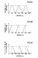
- the flow rate of the refrigerant in the return path 16 is proportional to the rate of change of the volume of the compression-discharge chamber 53b (see FIG. 4B) only during the period in which the rotation angle of the shaft 4 is 0 to 180 degrees. Change. Specifically, the flow velocity of the refrigerant in the return path 16 theoretically shows a sinusoidal profile in the period of 0 to 180 degrees and becomes zero in the period of 180 to 360 degrees.
- the refrigerant flowing into the accumulator 12 can only travel to the suction path 14. Therefore, the flow rate of the refrigerant in the introduction pipe 12b of the accumulator 12 substantially matches the difference between the flow rate of the refrigerant in the suction path 14 and the flow rate of the refrigerant in the return path 16.
- the flow rate of the refrigerant in the introduction pipe 12b theoretically shows a sinusoidal profile in the period of 180 to 360 degrees and becomes zero in the period of 0 to 180 degrees. .
- the refrigerant flow in the return path 16 rapidly decreases from the maximum flow velocity v to zero.
- the refrigerant flow in the introduction pipe 12b increases rapidly from zero to the maximum flow velocity v.
- the pressure wave transmitted to the suction path 14 may reduce the volumetric efficiency of the suction chamber 53a, which may reduce the efficiency of the rotary compressor 100.
- the return path 16 communicates with the suction path 14 via the internal space of the accumulator 12. According to this configuration, since the occurrence of water hammer can be prevented, it is possible to effectively suppress vibration, noise, and reduction in efficiency.
- the return port 3c and the back pressure chamber 18 are provided in the upper closing member 61, but the return port 3c and the back pressure chamber 18 are preferably provided in the lower closing member 62 ( For reference, see FIG. This is because, in this configuration, since the lubricating oil accumulates in the return port 3c while the return port 3c is closed in the high volume mode, the dead volume can be suppressed.
- the rotary compressor 200 includes a second compression mechanism 30 disposed above the compression mechanism 3 in addition to the compression mechanism 3 described in the first embodiment.
- the compression mechanism 3 described in the first embodiment and elements related thereto will be labeled with “first”.
- the cylinder 51 is the first cylinder 51
- the piston 52 is the first piston 52
- the vane 54 is the first vane 54
- the working chamber 53 is the first working chamber 53
- the compression mechanism 3 is the first compression mechanism 3
- the suction path 14 is This is denoted as a first suction path 14.
- the shaft 4 is provided with a second eccentric portion 4b in addition to the first eccentric portion 4a.
- the eccentric direction of the first eccentric portion 4a is shifted by 180 degrees from the eccentric direction of the second eccentric portion 4b. That is, the phase of the first piston 52 is deviated by 180 degrees from the phase of the second piston 82 described later and the rotation angle of the shaft 4.
- the second compression mechanism 30 is a positive displacement fluid mechanism, and is moved by the motor 2 to suck the refrigerant from the second suction port 30a, compress the refrigerant, and discharge the compressed refrigerant from the second discharge port 30b.
- the refrigerant is guided from the internal space of the accumulator 12 to the second suction port 30a through the second suction path 15.
- the suction volume of the second compression mechanism 30 is always constant. Note that one of the first suction path 14 and the second suction path 15 may branch from the other inside or outside the accumulator 12.
- the second compression mechanism 30 includes a second cylinder 81, a second piston 82, a second vane 84, a second spring 85, an intermediate plate 65, and a second closing member 66.
- the first compression mechanism 3 includes an intermediate plate 65 and a first closing member 64 instead of the upper closing member 61 and the lower closing member 62 described in the first embodiment. That is, the intermediate plate 65 is shared by the first compression mechanism 3 and the second compression mechanism 30.
- the intermediate plate 85 is sandwiched between the first cylinder 51 and the second cylinder 81, closes the first working chamber 53 from above, and closes a second working chamber 83 described later from below.
- the first closing member 64 closes the first working chamber 53 from the lower side, and the second closing member 66 closes the second working chamber 83 from the upper side. Further, the first closing member 64 and the second closing member 66 also function as bearings that rotatably support the shaft 4.
- the second cylinder 81 is disposed concentrically with the first cylinder 51.
- the second cylinder 81 is fitted into the second eccentric portion 4 b of the shaft 4 so that a second working chamber 83 is formed between the outer peripheral surface of the second cylinder 81 and the inner peripheral surface of the second cylinder 81.
- a second piston 82 is disposed.
- a second vane groove 86 is formed in the second cylinder 81.
- the second vane groove 86 accommodates a second vane 84 having a tip that contacts the outer peripheral surface of the second piston 82.
- the second spring 85 is disposed in the second vane groove 86 so as to push the second vane 84 toward the second piston 82.
- the second working chamber 83 between the second cylinder 81 and the second piston 82 is partitioned by a second vane 84, thereby forming a second suction chamber 83a and a second compression-discharge chamber 83b.
- the second vane 54 is disposed at a position that coincides with the first vane 54 in the axial direction of the shaft 4. For this reason, the timing at which the second piston 82 is located at the top dead center (the position at which the second vane 82 is most retracted) is the timing at which the first piston 81 is located at the top dead center (the position at which the first vane 52 is most retracted). And 180 degrees.
- the second cylinder 81 is provided with a second suction port 30a through which the refrigerant to be compressed flows into the second suction chamber 83a, and the compressed refrigerant flows out of the second compression-discharge chamber 83b.
- Two discharge ports 30 b are provided in the second closing member 66.
- the downstream end of the second suction path 15 is connected to the second suction port 30a.
- the second closing member 66 has a recess recessed from the upper surface of the second closing member 66 in the vicinity of the second vane 84, and the discharge port 30b extends from the lower surface of the second closing member 66 to the bottom surface of the recess. It extends. That is, the second discharge port 30b opens into the internal space 28 of the sealed container 1. Further, a second discharge valve 75 that opens and closes the discharge port 30b by elastic deformation and a stopper 76 that regulates the deformation amount of the second discharge valve 75 are disposed in the recess.
- the first discharge port 3 a, the return port 3 c, the back pressure chamber 18, and the communication path 60 are provided in the first closing member 64.
- the first closing member 64 is covered with a muffler 23 having an internal space that can receive the refrigerant discharged from the discharge port 3b. Further, the first closing member 64, the first cylinder 51, the intermediate plate 65, the second cylinder 81, and the second closing member 66 are provided with a flow path 35 that passes through them.
- the refrigerant compressed by the compression mechanism 3 moves from the internal space of the muffler 23 to the internal space 28 of the sealed container 1.
- the back pressure chamber 18 is partitioned by the cap 63 from the internal space of the muffler 23, and hence the internal space 28 of the sealed container 1.
- the second compression mechanism 30 since the second compression mechanism 30 is not provided with a return port, only the suction volume of the first compression mechanism 3 can be changed. Thus, by making it possible to change only the suction volume of the first compression mechanism 3, the production cost of the rotary compressor 200 can be suppressed.
- the first compression mechanism 3 is disposed on the side far from the motor 2, and the second compression mechanism 30 is disposed on the side close to the motor 2. That is, the motor 2, the second compression mechanism 30, and the first compression mechanism 3 are arranged in this order along the axial direction of the shaft 4. Since the second compression mechanism 30 has a constant suction volume, a large load torque is required even in the low volume mode. Therefore, when the second compression mechanism 30 is arranged on the side closer to the motor 2, the load applied to the shaft 4 in the low volume mode is reduced, and thereby the first closing member 64 and the second closing member functioning as bearings. The friction loss at 66 can be reduced.
- the compressed refrigerant flows into the internal space 28 of the sealed container 1 through the internal space of the muffler 23 and the flow path 35. Pressure loss generated by flowing can be reduced.
- the positional relationship between the first compression mechanism 3 and the second compression mechanism 30 is not limited to the above relationship, and may be reversed.
- V or “V / 2” can be selected as the suction volume of the first compression mechanism 3.
- suction volume of the second compression mechanism 30 is “V”, “2 V” or “1.5 V” can be selected as the sum of the suction volumes of the first compression mechanism 3 and the second compression mechanism 30.
- the suction volume of the first compression mechanism 3 can be made substantially zero.
- the return port 3c may be formed at a position close to the first discharge port 3b.
- the suction volume of the first compression mechanism 3 substantially zero does not necessarily mean that the suction volume of the first compression mechanism 3 is completely zero.
- the suction volume in the high volume mode is V
- the suction volume in the low volume mode is less than ⁇ 1- (1/2) 1/2 ⁇ V / 2, preferably less than V / 10.
- the position of the return port 3c can be determined. According to this configuration, it can be said that the first compression mechanism 3 does not perform compression work on the refrigerant in the low volume mode, and the function is lost.
- the first compression mechanism 3 may be disposed below the second compression mechanism 30 from the viewpoint of bearing reliability. preferable.
- the lower portion of the eccentric portion which is the end of the shaft, is generally thinner than the upper portion of the eccentric portion for the convenience of assembling the piston to the shaft. That is, if the first compression mechanism 3 is disposed below the second compression mechanism 30, the diameter of the portion of the shaft 4 supported by the first closing member 64 is the portion of the shaft 4 supported by the second closing member 66. It becomes smaller than the diameter.
- the bearing capacity of the first closing member 64 can be made smaller than the bearing capacity of the second closing member 66, and the load applied to the shaft 4 in the low volume mode can be reduced by moving the first compression mechanism 3 above the second compression mechanism 30. This can be reduced compared to the arrangement.
- the rotary compressor 300 of this embodiment has a configuration in which the positions of the first compression mechanism 3 and the second compression mechanism 30 are reversed in the rotary compressor 200 of the second embodiment. ing. Further, in the present embodiment, the second closing member 66 of the second compression mechanism 30 is connected to the second return port 30c for allowing the refrigerant to escape from the second compression-discharge chamber 83b, and to the second return port 30c. A back pressure chamber 19 is provided. The upstream end of the return path 16 is connected not only to the first back pressure chamber 18 but also to the second back pressure chamber 19.
- the angle from the second vane 84 to the second return port 30c is preferably substantially the same as the angle from the first vane 54 to the first return port 3c.
- substantially the same means that the difference between them is within 10 degrees.
- the second return port 30c may be formed at a position that forms 180 degrees with the second vane 84 when viewed from the axial center of the shaft 4, similarly to the first return port 3c.
- the relationship between the second discharge port 30b and the second piston 82 is the same as the preferable configuration described in the first embodiment (Db ⁇ Dd, Db ⁇ Rp1-Rp2, Lb It is preferable to satisfy ⁇ Rc).
- the second back pressure chamber 19 includes a recess formed on the lower surface of the second closing member 66 and a cap 67 covering the recess.
- the second back pressure chamber 19 is partitioned from the inner space of the muffler 23 and, consequently, the inner space 28 of the sealed container 1.
- the second closing member 66, the second cylinder 81, and the intermediate plate 65 are provided with a flow path 9 that passes through them and communicates the second back pressure chamber 19 and the relay chamber 57. In other words, the upstream end of the return path 16 is connected to the second back pressure chamber 19 via the relay chamber 57 and the flow path 9.
- a second check valve 77 for opening and closing the second return port 30c by elastic deformation and a stopper 78 for regulating the deformation amount of the second check valve 77 are arranged. That is, the second check valve 77 is a long and thin reed valve made of a thin metal plate.
- the amount of change in the suction volume can be made substantially the same between the first compression mechanism 3 and the second compression mechanism 30, and one rotation generated in the first compression mechanism 3 and the second compression mechanism 30.
- the rotation torque per unit becomes equal.
- the top dead center timing of the first compression mechanism 3 and the second compression mechanism 30 is shifted by 180 °, so that the rotational torque fluctuations generated in the shaft 4 can be canceled out.
- the rotational speed control of the motor 2 becomes easy and the motor efficiency is improved.
- the reliability of the device can be improved and the noise can be further reduced.
- the portion corresponding to the second cylinder 81 in the flow path 9 is enlarged, and the return path 16 is joined to the second cylinder 81 so that the upstream end of the return path 16 opens to the enlarged portion. Also good.
- the rotary compressor 400 of the present embodiment includes a first intermediate plate 68 and a second intermediate plate 69 that are superposed on each other instead of the intermediate plate 65 in the rotary compressor 300 of the third embodiment. It has an installed configuration. That is, the first compression mechanism 3 and the second compression mechanism have the first intermediate plate 68 and the second intermediate plate 69 separately.
- the first intermediate plate 68 closes the first working chamber 53 from below, and the second intermediate plate 69 closes the second working chamber from above.
- the first intermediate plate 68 is provided with the first return port 3c and the first back pressure chamber 18, and the second intermediate plate 69 is provided with the second return port 30c and the second back pressure chamber 19. ing.
- the first back pressure chamber 18 is partitioned from the internal space of the sealed container 1 by the second intermediate plate 69 and the second back pressure chamber 19 is defined by the first intermediate plate 68 of the internal space of the closed container 1. Therefore, the caps 63 and 67 as shown in FIG. 13 are not necessary, and the number of parts can be reduced. Further, if the first back pressure chamber 18 and the second back pressure chamber 19 are provided at positions that constitute a space in which they are continuous, the communication passage 9 as shown in FIG. 13 is not required, and the configuration is further simplified. can do.
- the refrigeration cycle apparatus 600 can be constructed using the rotary compressor 100 of the first embodiment.
- the refrigeration cycle apparatus 600 includes a rotary compressor 100, a radiator 602, an expansion mechanism 604, and an evaporator 606. These devices are connected in the above order by refrigerant pipes so as to form a refrigerant circuit.
- the radiator 602 is constituted by, for example, an air-refrigerant heat exchanger, and cools the refrigerant compressed by the rotary compressor 100.
- the expansion mechanism 604 is composed of, for example, an expansion valve, and expands the refrigerant cooled by the radiator 602.
- the evaporator 606 is composed of, for example, an air-refrigerant heat exchanger, and heats the refrigerant expanded by the expansion mechanism 604.
- the rotary compressors 200 to 400 of the second to fourth embodiments may be used.
- volume change valve 17 does not necessarily have to be an on-off valve.
- the volume change valve 17 does not necessarily have to be an on-off valve.
- the high-pressure refrigerant in the refrigerant circuit is guided to the back pressure chamber 18. It is also possible to use a three-way valve provided in the return path 16.
- the volume change valve 17 can be controlled so as to allow the refrigerant to return from the compression-discharge chamber 53b to the suction path 14 through the back pressure chamber 18 and the return path 16. . That is, the rotary compressor 100 is temporarily operated in the low volume mode at the time of startup.
- the present invention is useful for a compressor of a refrigeration cycle apparatus that can be used in a water heater, a hot water heater, an air conditioner, and the like.
- the present invention is particularly useful for a compressor of an air conditioner that requires a wide range of capabilities.
Abstract
Description
図1に示すように、本実施形態のロータリ圧縮機100は、圧縮機本体40、アキュームレータ12、吸入経路14、吐出経路11、帰還経路16、インバータ42および制御部44を備えている。
図10に示すように、本実施形態のロータリ圧縮機200は、第1実施形態で説明した圧縮機構3に加えて、圧縮機構3の上方に配置された第2圧縮機構30を備えている。以下、第1実施形態で説明した圧縮機構3およびこれに関連する要素に「第1」を付して標記する。例えば、シリンダ51を第1シリンダ51、ピストン52を第1ピストン52、ベーン54を第1ベーン54、作動室53を第1作動室53、圧縮機構3を第1圧縮機構3、吸入経路14を第1吸入経路14と標記する。
図13に示すように、本実施形態のロータリ圧縮機300は、第2実施形態のロータリ圧縮機200において第1圧縮機構3と第2圧縮機構30の位置を逆にしたような構成を有している。さらに、本実施形態では、第2圧縮機構30の第2閉塞部材66に、第2圧縮-吐出室83bから冷媒を逃がすための第2帰還ポート30cと、第2帰還ポート30cと連通する第2背圧室19が設けられている。そして、帰還経路16の上流端は、第1背圧室18だけでなく第2背圧室19にも接続されている。
図14に示すように、本実施形態のロータリ圧縮機400は、第3実施形態のロータリ圧縮機300において中間板65の代わりに互いに重ね合わされる第1中間板68および第2中間板69が配設された構成を有している。すなわち、第1圧縮機構3および第2圧縮機構は、第1中間板68と第2中間板69を別々に有している。
図15に示すように、第1実施形態のロータリ圧縮機100を使用して冷凍サイクル装置600を構築できる。冷凍サイクル装置600は、ロータリ圧縮機100、放熱器602、膨張機構604および蒸発器606を備えている。これらの機器は、冷媒回路を形成するように冷媒管によって上記の順番で接続されている。放熱器602は、例えば空気-冷媒熱交換器で構成されており、ロータリ圧縮機100で圧縮された冷媒を冷却する。膨張機構604は、例えば膨張弁で構成されており、放熱器602で冷却された冷媒を膨張させる。蒸発器606は、例えば空気-冷媒熱交換器で構成されており、膨張機構604で膨張した冷媒を加熱する。第1実施形態のロータリ圧縮機100に代えて、第2~第4実施形態のロータリ圧縮機200~400を使用してもよい。
本明細書で説明したいくつかの実施形態は、発明の要旨を逸脱しない範囲内で変更可能である。例えば、容積変更弁17は必ずしも開閉弁である必要はなく、容積変更弁17として、帰還経路16を通じた作動流体の流通を禁止するときは冷媒回路中の高圧冷媒を背圧室18に導くように帰還経路16に設けられた三方弁を用いることも可能である。
Claims (15)
- シリンダ、自身の外周面と前記シリンダの内周面との間に作動室が形成されるように前記シリンダの内部に配置されたピストン、前記作動室を吸入室と圧縮-吐出室とに仕切るベーン、圧縮するべき作動流体を前記吸入室に流入させる吸入ポート、圧縮された作動流体を前記圧縮-吐出室から流出させる吐出ポート、および前記圧縮-吐出室から作動流体を逃がすための帰還ポート、を含む圧縮機構と、
前記ピストンに嵌合する偏心部を有するシャフトと、
前記シャフトを回転させるモータと、
前記吸入ポートに作動流体を導く吸入経路と、
前記帰還ポートと連通する背圧室と、
前記背圧室内に配置され、弾性変形により前記帰還ポートを開閉するリードバルブ型の逆止弁と、
前記背圧室から作動流体を前記吸入経路へ戻す帰還経路と、
前記帰還経路に設けられ、前記圧縮機構の吸入容積を相対的に小さくすべきときには前記帰還経路を通じた作動流体の流通を許容し、前記吸入容積を相対的に大きくすべきときには前記帰還経路を通じた作動流体の流通を禁止して前記背圧室内の圧力を増加させる容積変更弁と、
前記モータを駆動するインバータと、
前記吸入容積の減少を前記モータの回転数の増加で補償するように前記容積変更弁および前記インバータを制御する制御部と、
を備えたロータリ圧縮機。 - 前記圧縮機構は、前記シャフトの軸方向の両側から前記作動室を閉塞する一対の閉塞部材をさらに含み、
前記一対の閉塞部材の一方に、前記帰還ポートおよび前記背圧室が設けられている、請求項1に記載のロータリ圧縮機。 - 前記圧縮機構および前記モータを収容する密閉容器をさらに備え、
前記吐出ポートは、前記密閉容器の内部空間に開口しており、
前記背圧室は、前記密閉容器の内部空間から区画されている、請求項1または2に記載のロータリ圧縮機。 - 作動流体を保持できる内部空間を有し、前記吸入経路および前記帰還経路が接続されたアキュームレータをさらに備え、
前記アキュームレータの前記内部空間を介して前記帰還経路が前記吸入経路と連通している、請求項1~3のいずれか一項に記載のロータリ圧縮機。 - 前記シリンダを第1シリンダ、前記ピストンを第1ピストン、前記ベーンを第1ベーン、前記作動室を第1作動室、前記圧縮室を第1圧縮室、前記圧縮-吐出室を第1圧縮-吐出室、前記吸入ポートを第1吸入ポート、前記吐出ポートを第1吐出ポート、前記圧縮機構を第1圧縮機構、前記偏心部を第1偏心部、前記吸入経路を第1吸入経路と定義したとき、
当該ロータリ圧縮機は、第2シリンダ、自身の外周面と前記第2シリンダの内周面との間に第2作動室が形成されるように前記第2シリンダの内部に配置された第2ピストン、前記第2作動室を第2吸入室と第2圧縮-吐出室とに仕切る第2ベーン、圧縮するべき作動流体を前記第2吸入室に流入させる第2吸入ポート、および圧縮された作動流体を前記第2圧縮-吐出室から流出させる第2吐出ポート、を含む第2圧縮機構と、作動流体を前記アキュームレータの内部空間から前記第2吸入ポートに導く第2吸入経路と、をさらに備え、
前記シャフトは、前記第2ピストンと嵌合する第2偏心部をさらに有する、請求項4に記載のロータリ圧縮機。 - 前記第2圧縮機構の吸入容積は、常に一定である、請求項5に記載のロータリ圧縮機。
- 前記帰還経路を通じた作動流体の流通が許容される低容積モードにおいて、前記第1圧縮機構の前記吸入容積が実質的にゼロである、請求項6に記載のロータリ圧縮機。
- 前記第1圧縮機構および前記第2圧縮機構は、前記第1シリンダと前記第2シリンダとに挟持され、前記第1作動室および前記第2作動室を前記シャフトの軸方向の一方から閉塞する中間板を共有しており、
前記第1圧縮機構は、前記中間板と反対側から前記第1作動室を閉塞する第1閉塞部材を含み、
前記第2圧縮機構は、前記中間板と反対側から前記第2作動室を閉塞する第2閉塞部材を含み、
前記第1閉塞部材および前記第2閉塞部材は、前記シャフトを回転自在に支持する軸受としても機能し、
前記シャフトにおける前記外側第1閉塞部材に支持される部分の直径は、前記シャフトにおける前記外側第2閉塞部材に支持される部分の直径よりも小さい、請求項7に記載のロータリ圧縮機。 - 前記帰還ポートを第1帰還ポート、前記背圧室を第1背圧室、前記逆止弁を第1逆止弁と定義したとき、
前記第2圧縮機構は、前記第2圧縮-吐出室から作動流体を逃がすための第2帰還ポートをさらに含み、
当該ロータリ圧縮機は、前記第2帰還ポートと連通する第2背圧室と、前記第2背圧室内に配置され、弾性変形により前記第2帰還ポートを開閉するリードバルブ型の第2逆止弁と、をさらに備え、
前記帰還経路の上流端は、前記第1背圧室だけでなく前記第2背圧室にも接続されている、請求項5に記載のロータリ圧縮機。 - 前記シャフトの回転方向において、前記第1ベーンから前記第1帰還ポートまでの角度は、前記第2ベーンから前記第2帰還ポートまでの角度と略同じである、請求項9に記載のロータリ圧縮機。
- 前記第1圧縮機構および前記第2圧縮機構は、前記第1シリンダと前記第2シリンダとに挟持され、前記第1作動室および前記第2作動室を前記シャフトの軸方向の一方から閉塞する中間板を共有しており、
前記第1圧縮機構は、前記中間板と反対側から前記第1作動室を閉塞する第1閉塞部材を含み、
前記第2圧縮機構は、前記中間板と反対側から前記第2作動室を閉塞する第2閉塞部材を含み、
前記第1帰還ポートおよび前記第1背圧室は前記第1閉塞部材に設けられ、前記第2帰還ポートおよび前記第2背圧室は前記第2閉塞部材に設けられている、請求項9または10に記載のロータリ圧縮機。 - 前記第1圧縮機構は、第2圧縮機構側から前記第1作動室を閉塞する第1中間板と、前記第1中間板と反対側から前記第1作動室を閉塞する第1閉塞部材と、を含み、
前記第2圧縮機構は、前記第1圧縮機構側から前記第2作動室を閉塞する第2中間板と、前記第2中間板と反対側から前記第2作動室を閉塞する第2閉塞部材と、を含み、
前記第1中間板と前記第2中間板は、互いに重ね合わされ、
前記第1帰還ポートおよび前記第1背圧室は前記第1中間板に設けられ、前記第2帰還ポートおよび前記第2背圧室は前記第2中間板に設けられている、請求項9または10に記載のロータリ圧縮機。 - 前記帰還ポートの直径Dbが、前記吐出ポートの直径Ddと、Db≦Ddの関係にある請求項1~4のいずれか1項に記載のロータリ圧縮機。
- 前記帰還ポートの直径Dbが、前記ピストンの外半径Rp1と内半径Rp2と、Db<Rp1-Rp2の関係にある請求項1~4のいずれか1項に記載のロータリ圧縮機。
- 前記帰還ポートの中心と前記シリンダの内径中心との距離Lbが、前記シリンダの内半径Rcと、Lb<Rcの関係にある請求項1~4のいずれか1項に記載のロータリ圧縮機。
Priority Applications (3)
| Application Number | Priority Date | Filing Date | Title |
|---|---|---|---|
| US14/004,041 US9546659B2 (en) | 2011-03-10 | 2012-02-23 | Rotary compressor |
| JP2013503365A JP5807175B2 (ja) | 2011-03-10 | 2012-02-23 | ロータリ圧縮機 |
| CN201280012308.7A CN103429902B (zh) | 2011-03-10 | 2012-02-23 | 旋转式压缩机 |
Applications Claiming Priority (2)
| Application Number | Priority Date | Filing Date | Title |
|---|---|---|---|
| JP2011052364 | 2011-03-10 | ||
| JP2011-052364 | 2011-03-10 |
Publications (1)
| Publication Number | Publication Date |
|---|---|
| WO2012120808A1 true WO2012120808A1 (ja) | 2012-09-13 |
Family
ID=46797784
Family Applications (1)
| Application Number | Title | Priority Date | Filing Date |
|---|---|---|---|
| PCT/JP2012/001235 WO2012120808A1 (ja) | 2011-03-10 | 2012-02-23 | ロータリ圧縮機 |
Country Status (4)
| Country | Link |
|---|---|
| US (1) | US9546659B2 (ja) |
| JP (1) | JP5807175B2 (ja) |
| CN (1) | CN103429902B (ja) |
| WO (1) | WO2012120808A1 (ja) |
Cited By (1)
| Publication number | Priority date | Publication date | Assignee | Title |
|---|---|---|---|---|
| JP2015135214A (ja) * | 2014-01-17 | 2015-07-27 | 株式会社東芝 | 空気調和装置 |
Families Citing this family (1)
| Publication number | Priority date | Publication date | Assignee | Title |
|---|---|---|---|---|
| CN109595166B (zh) * | 2017-09-30 | 2024-01-05 | 广东美芝制冷设备有限公司 | 压缩机 |
Citations (6)
| Publication number | Priority date | Publication date | Assignee | Title |
|---|---|---|---|---|
| JPS62255212A (ja) * | 1986-04-30 | 1987-11-07 | Honda Motor Co Ltd | 車輌用冷媒圧縮機装置 |
| JPS6321792U (ja) * | 1986-07-28 | 1988-02-13 | ||
| JPH02118362A (ja) * | 1988-10-26 | 1990-05-02 | Hitachi Ltd | 容量制御空調機 |
| JPH02191882A (ja) * | 1989-01-20 | 1990-07-27 | Hitachi Ltd | 圧縮機の容量制御装置及びその制御方法 |
| JP2006022761A (ja) * | 2004-07-09 | 2006-01-26 | Matsushita Electric Ind Co Ltd | 圧縮機 |
| JP2006161701A (ja) * | 2004-12-08 | 2006-06-22 | Matsushita Electric Ind Co Ltd | 圧縮機 |
Family Cites Families (13)
| Publication number | Priority date | Publication date | Assignee | Title |
|---|---|---|---|---|
| JPS56129795A (en) * | 1980-03-12 | 1981-10-12 | Nippon Soken Inc | Rotary compressor |
| JPS61184365A (ja) | 1985-02-08 | 1986-08-18 | 松下電器産業株式会社 | 空気調和機の運転制御装置 |
| JPS6221792U (ja) * | 1985-07-19 | 1987-02-09 | ||
| JP4639413B2 (ja) * | 1999-12-06 | 2011-02-23 | ダイキン工業株式会社 | スクロール圧縮機および空気調和機 |
| KR100452774B1 (ko) * | 2002-10-09 | 2004-10-14 | 삼성전자주식회사 | 로터리 압축기 |
| JP4343627B2 (ja) | 2003-03-18 | 2009-10-14 | 東芝キヤリア株式会社 | ロータリ式密閉形圧縮機および冷凍サイクル装置 |
| KR20040086892A (ko) * | 2003-03-22 | 2004-10-13 | 삼성전자주식회사 | 로터리압축기 |
| JP4447859B2 (ja) * | 2003-06-20 | 2010-04-07 | 東芝キヤリア株式会社 | ロータリ式密閉形圧縮機および冷凍サイクル装置 |
| KR100629872B1 (ko) * | 2004-08-06 | 2006-09-29 | 엘지전자 주식회사 | 로터리 압축기의 용량 가변 장치 및 이를 구비한 에어콘의운전 방법 |
| US7665973B2 (en) * | 2004-11-01 | 2010-02-23 | Lg Electronics Inc. | Apparatus for changing capacity of multi-stage rotary compressor |
| CN100467875C (zh) * | 2005-02-04 | 2009-03-11 | Lg电子株式会社 | 绕动叶片压缩机及其活塞阀 |
| CN101684800A (zh) * | 2008-09-27 | 2010-03-31 | 乐金电子(天津)电器有限公司 | 旋转式压缩机 |
| KR101637446B1 (ko) * | 2009-12-11 | 2016-07-07 | 엘지전자 주식회사 | 로터리 압축기 |
-
2012
- 2012-02-23 US US14/004,041 patent/US9546659B2/en not_active Expired - Fee Related
- 2012-02-23 CN CN201280012308.7A patent/CN103429902B/zh not_active Expired - Fee Related
- 2012-02-23 WO PCT/JP2012/001235 patent/WO2012120808A1/ja active Application Filing
- 2012-02-23 JP JP2013503365A patent/JP5807175B2/ja not_active Expired - Fee Related
Patent Citations (6)
| Publication number | Priority date | Publication date | Assignee | Title |
|---|---|---|---|---|
| JPS62255212A (ja) * | 1986-04-30 | 1987-11-07 | Honda Motor Co Ltd | 車輌用冷媒圧縮機装置 |
| JPS6321792U (ja) * | 1986-07-28 | 1988-02-13 | ||
| JPH02118362A (ja) * | 1988-10-26 | 1990-05-02 | Hitachi Ltd | 容量制御空調機 |
| JPH02191882A (ja) * | 1989-01-20 | 1990-07-27 | Hitachi Ltd | 圧縮機の容量制御装置及びその制御方法 |
| JP2006022761A (ja) * | 2004-07-09 | 2006-01-26 | Matsushita Electric Ind Co Ltd | 圧縮機 |
| JP2006161701A (ja) * | 2004-12-08 | 2006-06-22 | Matsushita Electric Ind Co Ltd | 圧縮機 |
Cited By (1)
| Publication number | Priority date | Publication date | Assignee | Title |
|---|---|---|---|---|
| JP2015135214A (ja) * | 2014-01-17 | 2015-07-27 | 株式会社東芝 | 空気調和装置 |
Also Published As
| Publication number | Publication date |
|---|---|
| JPWO2012120808A1 (ja) | 2014-07-17 |
| US20130343942A1 (en) | 2013-12-26 |
| CN103429902B (zh) | 2015-09-02 |
| US9546659B2 (en) | 2017-01-17 |
| CN103429902A (zh) | 2013-12-04 |
| JP5807175B2 (ja) | 2015-11-10 |
Similar Documents
| Publication | Publication Date | Title |
|---|---|---|
| JP6057181B2 (ja) | ロータリ圧縮機 | |
| JP5631398B2 (ja) | ロータリ圧縮機及び冷凍サイクル装置 | |
| JP4856091B2 (ja) | 容量可変型ロータリ圧縮機及びこれを備える冷却システム | |
| JP5306478B2 (ja) | ヒートポンプ装置、二段圧縮機及びヒートポンプ装置の運転方法 | |
| JP4903826B2 (ja) | スクロール流体機械 | |
| JP2008240667A (ja) | ロータリ圧縮機 | |
| JP5228905B2 (ja) | 冷凍装置 | |
| WO2012042894A1 (ja) | 容積型圧縮機 | |
| KR100620044B1 (ko) | 로터리 압축기의 용량 가변 장치 | |
| JP5807175B2 (ja) | ロータリ圧縮機 | |
| JP5338314B2 (ja) | 圧縮機および冷凍装置 | |
| JP2012172571A (ja) | ロータリ圧縮機 | |
| JP5515289B2 (ja) | 冷凍装置 | |
| JP2013053579A (ja) | ロータリ圧縮機 | |
| JP2013104368A (ja) | ロータリ圧縮機 | |
| KR100539561B1 (ko) | 이중용량 로터리 압축기 | |
| KR100565647B1 (ko) | 이중용량 로터리 압축기 | |
| JP2013224595A (ja) | 2気筒ロータリ圧縮機 | |
| KR100677527B1 (ko) | 로터리 압축기 | |
| JP5321055B2 (ja) | 冷凍装置 | |
| JP4655051B2 (ja) | 回転式圧縮機 | |
| JP5835299B2 (ja) | 冷凍装置 | |
| JP2013024194A (ja) | 冷凍装置 | |
| JP2008190492A5 (ja) | ||
| JP2008190493A (ja) | 回転式圧縮機 |
Legal Events
| Date | Code | Title | Description |
|---|---|---|---|
| 121 | Ep: the epo has been informed by wipo that ep was designated in this application |
Ref document number: 12755312 Country of ref document: EP Kind code of ref document: A1 |
|
| ENP | Entry into the national phase |
Ref document number: 2013503365 Country of ref document: JP Kind code of ref document: A |
|
| WWE | Wipo information: entry into national phase |
Ref document number: 14004041 Country of ref document: US |
|
| NENP | Non-entry into the national phase |
Ref country code: DE |
|
| 122 | Ep: pct application non-entry in european phase |
Ref document number: 12755312 Country of ref document: EP Kind code of ref document: A1 |