WO2012117883A1 - 積層式電池 - Google Patents
積層式電池 Download PDFInfo
- Publication number
- WO2012117883A1 WO2012117883A1 PCT/JP2012/054060 JP2012054060W WO2012117883A1 WO 2012117883 A1 WO2012117883 A1 WO 2012117883A1 JP 2012054060 W JP2012054060 W JP 2012054060W WO 2012117883 A1 WO2012117883 A1 WO 2012117883A1
- Authority
- WO
- WIPO (PCT)
- Prior art keywords
- positive
- electrode current
- current collecting
- terminal
- positive electrode
- Prior art date
- Legal status (The legal status is an assumption and is not a legal conclusion. Google has not performed a legal analysis and makes no representation as to the accuracy of the status listed.)
- Ceased
Links
Images





Classifications
-
- H—ELECTRICITY
- H01—ELECTRIC ELEMENTS
- H01M—PROCESSES OR MEANS, e.g. BATTERIES, FOR THE DIRECT CONVERSION OF CHEMICAL ENERGY INTO ELECTRICAL ENERGY
- H01M10/00—Secondary cells; Manufacture thereof
- H01M10/05—Accumulators with non-aqueous electrolyte
- H01M10/058—Construction or manufacture
- H01M10/0585—Construction or manufacture of accumulators having only flat construction elements, i.e. flat positive electrodes, flat negative electrodes and flat separators
-
- H—ELECTRICITY
- H01—ELECTRIC ELEMENTS
- H01M—PROCESSES OR MEANS, e.g. BATTERIES, FOR THE DIRECT CONVERSION OF CHEMICAL ENERGY INTO ELECTRICAL ENERGY
- H01M50/00—Constructional details or processes of manufacture of the non-active parts of electrochemical cells other than fuel cells, e.g. hybrid cells
- H01M50/10—Primary casings; Jackets or wrappings
- H01M50/172—Arrangements of electric connectors penetrating the casing
- H01M50/174—Arrangements of electric connectors penetrating the casing adapted for the shape of the cells
- H01M50/178—Arrangements of electric connectors penetrating the casing adapted for the shape of the cells for pouch or flexible bag cells
-
- H—ELECTRICITY
- H01—ELECTRIC ELEMENTS
- H01M—PROCESSES OR MEANS, e.g. BATTERIES, FOR THE DIRECT CONVERSION OF CHEMICAL ENERGY INTO ELECTRICAL ENERGY
- H01M50/00—Constructional details or processes of manufacture of the non-active parts of electrochemical cells other than fuel cells, e.g. hybrid cells
- H01M50/50—Current conducting connections for cells or batteries
- H01M50/531—Electrode connections inside a battery casing
- H01M50/534—Electrode connections inside a battery casing characterised by the material of the leads or tabs
-
- H—ELECTRICITY
- H01—ELECTRIC ELEMENTS
- H01M—PROCESSES OR MEANS, e.g. BATTERIES, FOR THE DIRECT CONVERSION OF CHEMICAL ENERGY INTO ELECTRICAL ENERGY
- H01M50/00—Constructional details or processes of manufacture of the non-active parts of electrochemical cells other than fuel cells, e.g. hybrid cells
- H01M50/50—Current conducting connections for cells or batteries
- H01M50/543—Terminals
- H01M50/547—Terminals characterised by the disposition of the terminals on the cells
- H01M50/55—Terminals characterised by the disposition of the terminals on the cells on the same side of the cell
-
- H—ELECTRICITY
- H01—ELECTRIC ELEMENTS
- H01M—PROCESSES OR MEANS, e.g. BATTERIES, FOR THE DIRECT CONVERSION OF CHEMICAL ENERGY INTO ELECTRICAL ENERGY
- H01M50/00—Constructional details or processes of manufacture of the non-active parts of electrochemical cells other than fuel cells, e.g. hybrid cells
- H01M50/50—Current conducting connections for cells or batteries
- H01M50/543—Terminals
- H01M50/552—Terminals characterised by their shape
- H01M50/553—Terminals adapted for prismatic, pouch or rectangular cells
-
- H—ELECTRICITY
- H01—ELECTRIC ELEMENTS
- H01M—PROCESSES OR MEANS, e.g. BATTERIES, FOR THE DIRECT CONVERSION OF CHEMICAL ENERGY INTO ELECTRICAL ENERGY
- H01M50/00—Constructional details or processes of manufacture of the non-active parts of electrochemical cells other than fuel cells, e.g. hybrid cells
- H01M50/50—Current conducting connections for cells or batteries
- H01M50/543—Terminals
- H01M50/562—Terminals characterised by the material
-
- Y—GENERAL TAGGING OF NEW TECHNOLOGICAL DEVELOPMENTS; GENERAL TAGGING OF CROSS-SECTIONAL TECHNOLOGIES SPANNING OVER SEVERAL SECTIONS OF THE IPC; TECHNICAL SUBJECTS COVERED BY FORMER USPC CROSS-REFERENCE ART COLLECTIONS [XRACs] AND DIGESTS
- Y02—TECHNOLOGIES OR APPLICATIONS FOR MITIGATION OR ADAPTATION AGAINST CLIMATE CHANGE
- Y02E—REDUCTION OF GREENHOUSE GAS [GHG] EMISSIONS, RELATED TO ENERGY GENERATION, TRANSMISSION OR DISTRIBUTION
- Y02E60/00—Enabling technologies; Technologies with a potential or indirect contribution to GHG emissions mitigation
- Y02E60/10—Energy storage using batteries
-
- Y—GENERAL TAGGING OF NEW TECHNOLOGICAL DEVELOPMENTS; GENERAL TAGGING OF CROSS-SECTIONAL TECHNOLOGIES SPANNING OVER SEVERAL SECTIONS OF THE IPC; TECHNICAL SUBJECTS COVERED BY FORMER USPC CROSS-REFERENCE ART COLLECTIONS [XRACs] AND DIGESTS
- Y02—TECHNOLOGIES OR APPLICATIONS FOR MITIGATION OR ADAPTATION AGAINST CLIMATE CHANGE
- Y02P—CLIMATE CHANGE MITIGATION TECHNOLOGIES IN THE PRODUCTION OR PROCESSING OF GOODS
- Y02P70/00—Climate change mitigation technologies in the production process for final industrial or consumer products
- Y02P70/50—Manufacturing or production processes characterised by the final manufactured product
Definitions
- the present invention relates to a stacked battery having a large capacity and a high rate characteristic used for a robot, an electric vehicle, a backup power source, and the like, and in particular, has a large number of stacked layers and requires connection between a large number of electrode plate leads and current collecting terminals.
- the present invention relates to a large-capacity lithium ion battery in which connection resistance with each electrode plate is made uniform.
- Such a lithium ion battery can be roughly classified into a battery type in which an electrode body obtained by winding a positive and negative electrode plate through a separator is enclosed in an outer package, and a rectangular positive electrode plate.
- the battery is referred to as a laminated battery in which a laminated electrode body in which negative electrode plates are alternately laminated via separators is housed in an exterior body.
- the specific configuration of the laminated electrode body in the latter laminated battery is as follows: a sheet-like positive electrode plate in which a positive electrode plate lead is extended, and a sheet shape in which a negative electrode plate lead is extended. And the required number of electrode plates extending from each electrode plate were joined to the current collector terminals of the positive and negative electrodes, respectively, through a rectangular separator having substantially the same shape as the negative electrode plate. It has a structure.
- the positive and negative electrode plate leads and the positive and negative electrodes are connected to the positive and negative electrode current collector terminals (hereinafter also referred to as “positive and negative electrode current collectors”).
- positive and negative electrode current collectors For the purpose of improving the connection reliability with the current collector terminal and saving the space of the positive and negative current collectors, for example, the following structures have been proposed.
- Patent Document 1 positive and negative terminals (leads) led out from the positive and negative plates are bent up and down inside the battery to form a step shape, and the step shape portion is supported on the inner walls of the upper and lower exterior members. Thus, it is disclosed that the positional accuracy in the thickness direction of the positive and negative electrode terminals is ensured.
- patent document 2 it is set as the structure which improves space efficiency by folding the positive / negative electrode terminal (lead) pulled out from the positive / negative electrode board, and it makes it fold in the state which gave the slack beforehand to the positive / negative electrode terminal at this time.
- positive electrode and negative electrode terminals are prevented from stretching, wrinkling, twisting, and the like.
- the lead terminal led out from the positive and negative electrode plates is provided with an easy-to-bend portion whose width or thickness is locally reduced, thereby preventing a chipping failure at the time of bending of the lead terminal and ensuring reliability.
- a high connection structure is disclosed.
- connection resistance value between each electrode plate and the current collector terminal becomes non-uniform, and the current flowing into each electrode plate varies, especially when used at a high rate.
- the uneven distribution occurs, and the cycle characteristics deteriorate due to partial overdischarge and overcharge.
- the present inventors provide a local penetration part such as a notch in the current collection terminal at the junction between the current collection terminal and the electrode plate lead, and the current collection terminal and the electrode plate at a part other than this penetration part.
- a local penetration part such as a notch in the current collection terminal at the junction between the current collection terminal and the electrode plate lead, and the current collection terminal and the electrode plate at a part other than this penetration part.
- the connection resistance value between each electrode plate and the current collecting terminal is made uniform and flows into each electrode plate. It has been found that it is possible to effectively suppress a decrease in cycle characteristics due to variations in current value, and a patent application (Japanese Patent Application No. 2009-216330; hereinafter also referred to as “prior application”) has been filed regarding this content.
- the configuration of the above-mentioned prior application is such that only the electrode plate lead is joined at the through portion provided in the current collecting terminal, so that an increase in the area of the joined portion can also be avoided, thus saving space or volume It is also desirable from the viewpoint of energy density.
- Patent Document 1 discloses that a slit 211 extending in the extending direction is formed in the positive electrode terminal 210.
- the upper side step portion 212 and the lower side step portion 213 are bent up and down on both side portions, and the upper step portion 212 and the lower step portion 213 are supported on the inner walls of the upper exterior member 106 and the lower exterior member 107 to form a positive electrode.
- the position accuracy of the terminal 210 in the thickness direction can be ensured, and is completely different in structure and function from the penetrating portion in the prior application. There is no mention or suggestion of joining only.
- An object of the present invention is to improve the invention according to the above-mentioned prior application, and to provide a stacked battery that is further excellent in reliability in the positive and negative electrode current collectors.
- the laminated battery according to the present invention is: A plurality of positive and negative electrode plates are alternately stacked via separators, and the positive and negative current collecting leads extending from the positive and negative electrode plates are respectively connected to the positive and negative current collecting terminals.
- a laminated battery comprising a laminated electrode body having a structure in which a plurality of sheets are laminated and joined, At least one of the positive electrode current collector terminal and the negative electrode current collector terminal is a first piece substantially parallel to the positive electrode plate and the negative electrode plate in the laminated electrode body, and the lamination direction of the positive electrode plate and the negative electrode plate in the laminated electrode body; Bend-shaped to have a second piece that is substantially parallel; A penetrating portion extending from the first piece to the second piece in at least one of the positive electrode current collecting terminal and the negative electrode current collecting terminal is formed, At least one of the positive electrode current collecting lead and the negative electrode current collecting lead is bonded to the second piece in at least one of the positive electrode current collecting terminal and the negative electrode current collecting terminal, and is laminated in a region where the through portion is formed.
- the positive electrode current collector leads and / or the negative electrode current collector leads are bonded to each other.
- substantially parallel implies not only strict (complete) parallel but also an aspect having a certain degree of inclination (for example, about + 10 ° to ⁇ 10 °).
- the positive and negative current collecting terminals are notched so as to be recessed or angularly dropped from the end, or the positive and negative current collecting terminals are provided with holes (openings). Any of these are included.
- the stacked positive electrode current collector leads and / or the negative electrode current collector leads are joined in the region where the through portion is formed, that is, the region where the positive and negative current collector terminals are not present.
- a closed circuit is formed, whereby the connection resistance is made uniform. Therefore, even when charging / discharging at a high rate, the current value flowing into each electrode plate does not vary, and good cycle characteristics can be obtained. Further, since the bonding is performed in the region where the penetrating portion is formed, an increase in the area of the bonding portion can be avoided and the volume energy density can be maintained well.
- the positive and negative current collecting terminals are substantially parallel to the first piece substantially parallel to the positive and negative electrode plates in the laminated electrode body and the lamination direction of the positive and negative electrode plates in the laminated electrode body. It is the structure bent and formed so that it may have a 2nd piece, ie, the structure bent and formed so that it may become the side view shape (L shape) which has the said 1st piece and 2nd piece.
- the positive and negative current collecting terminals can be joined to the positive and negative current collecting leads with a second piece substantially parallel to the lamination direction of the positive and negative electrode plates in the laminated electrode body. A large connection area between the positive and negative current collecting terminals and the positive and negative current collecting leads can be secured without increasing the space in the outgoing direction.
- the penetrating portion is formed so as to expand from the first piece to the second piece of the positive and negative current collecting terminals, deformation of the positive and negative current collecting terminals during bending can be effectively suppressed.
- the bending forming is usually performed after forming the penetrating portion.
- the end portion of the penetrating portion (for example, a corner) is easily deformed by the bending stress. .
- the deformed portion breaks through the inner insulating layer of the laminate outer package and comes into contact with the metal layer of the laminate outer package.
- the penetrating portion is formed so as to extend from the first piece to the second piece in the positive and negative current collecting terminals. That is, since the positive and negative electrode current collecting terminals are bent at the position where the penetrating portion is formed, the bending stress is reduced and it is difficult to act on portions other than the bent portion. Therefore, useless deformation of the positive and negative current collecting terminals other than the bent portion can be effectively suppressed without causing a loss of volume energy density.
- the through portion is formed only in the second piece of the positive and negative current collecting terminals and the positive and negative current collecting terminals are bent at a distance from the through portion, the dimension of the through portion is the second. It becomes smaller than the height of the piece (width in the stacking direction of the positive and negative electrode plates). Therefore, in this case, when the thickness of the laminated electrode body is reduced, the dimension of the through portion is reduced along with the height of the second piece, so that the area of the joint portion where the positive and negative current collecting leads are joined in the through portion forming region is also reduced. As a result, as a result, the welding tip is downsized, that is, the welding energy is reduced, and the joining strength is also lowered.
- the through portion is formed so as to expand from the first piece to the second piece in the positive and negative current collecting terminals, it is possible to ensure a large area of the joint portion. it can.
- At least one of the positive current collecting lead and the negative current collecting lead is joined to a second piece of at least one of the positive current collecting terminal and the negative current collecting terminal (hereinafter also referred to as “lead-terminal joining portion”). ) And a joint where the stacked positive electrode current collector leads and / or the negative electrode current collector leads are bonded in the region where the penetrating portion is formed (hereinafter also referred to as “lead-limited bond portion”), It is desirable that the positive electrode current collecting lead or the negative electrode current collecting lead be arranged along a direction substantially perpendicular to the extending direction of the negative electrode current collecting lead.
- the “direction substantially perpendicular to the extending direction of the positive current collecting lead or the negative current collecting lead” means strictly 90 ° with respect to the extending direction of the positive current collecting lead or the negative current collecting lead. This includes not only a direction that forms an angle (right angle) but also a direction that forms an angle of, for example, about 80 to 100 ° with respect to the extending direction of the positive electrode current collecting lead or the negative electrode current collecting lead.
- the lead-terminal joint and the lead-limited joint are in a positional relationship such that the positive and negative current collector leads are aligned along the extending direction of the positive and negative current collector leads, these joints are greatly increased in the extending direction of the positive and negative current collector leads. Occupies the area.
- the lead-terminal joint and the lead-limited joint are arranged along a direction substantially perpendicular to the extending direction of the positive and negative current collecting leads, that is, the lead-terminal joint.
- the extension direction of the positive and negative electrode current collector leads is the vertical direction
- the lead limited joint part is aligned in the horizontal direction
- these joints are connected in the extension direction of the positive and negative electrode current collector leads.
- the area occupied by the part can be reduced. In other words, the space occupied by these joints can be compactly accommodated so as not to be elongated in the extending direction of the positive and negative electrode current collecting leads, so that the volume energy density can be improved.
- the positive electrode current collector terminal and the negative electrode current collector terminal are attached with a resin sealing material for securing hermeticity when sealing the exterior body, and the resin sealing material is a region where the through portion is formed. It is desirable that they are attached so as to overlap.
- the position where the resin sealing material is attached to the positive and negative current collecting terminals is the position where the outer package is sealed so as to include the positive and negative current collecting parts from the outside. Therefore, if the resin sealing material is attached so as to overlap the region where the through-holes are formed in the positive and negative current collector terminals, the positive and negative current collectors are more likely to extend in the extending direction of the positive and negative current collector leads. The space can be saved.
- the positional relationship is such that the end in the depth direction of the penetrating portion (the end on the current collecting portion pulling direction side, that is, the end on the positive current collecting lead side) enters the inside of the resin sealing material. As a result, the laminated electrode body and the bent portions of the positive and negative current collecting terminals are brought as close as possible, and the loss of volume energy density is reduced.
- the laminated electrode body side end of the resin sealing material is disposed so as to be positioned at a fold line of the positive current collector terminal and / or the negative current collector terminal.
- the penetrating portion is formed so as to extend from the first piece to the second piece of the positive and negative current collecting terminals.
- the positive and negative current collecting terminals are bent at the position where the through portion is formed. Therefore, the folding line of the positive and negative current collecting terminals is necessarily positioned so as to pass through the through portion. At this time, the folding line of the positive and negative current collecting terminals may be at any position as long as it passes through the through portion, that is, at any position as long as the positive and negative current collecting terminal is at the formation position of the through portion.
- the positive and negative electrodes in the extending direction of the positive and negative current collector leads The space occupied by the current collecting terminals can be reduced as much as possible. Therefore, it is desirable in terms of space saving of the positive and negative current collecting portions.
- At least one of the lead-terminal joint and the lead limited joint is joined by ultrasonic welding.
- the lead limited joining portion may be used.
- the effect of the configuration in which the positive and negative electrode current collecting leads are joined together is exhibited, and there is also an advantage that the joining work can be performed with simple equipment, and the battery can be easily and inexpensively manufactured.
- welding is preferable because the resistance can be made more uniform.
- a welding method for example, a resistance welding method or a laser welding method can be used, but ultrasonic welding is particularly desirable in terms of welding strength and the like.
- the thin positive and negative current collecting leads are welded together (because the thick current collecting terminals are not present), so that welding is performed with a small output. be able to.
- At least one of the lead-terminal joint and the lead limited joint be joined at a plurality of points.
- bonding at the lead-terminal bonding portion or the lead limited bonding portion can be more reliably performed, and the connection resistance value can be made more uniform.
- the stacked battery is a lithium ion battery.
- the number of stacked positive and negative electrode plates is 30 or more.
- the lead-terminal joint is liable to be particularly inferior. Therefore, the positive and negative current collecting leads should be joined at the lead-limited joint. The effect by the structure made will be further exhibited.
- the laminated battery of the present invention it is possible to effectively suppress unnecessary deformation of the positive and negative electrode current collecting terminals other than the bent portion without causing a loss of volume energy density. It is difficult to cause a short circuit with the laminate outer package at the portion, and a laminated battery having excellent reliability can be obtained.
- the figure (a) is a top view of a positive electrode
- the figure (b) is a perspective view of a separator
- the figure (c) is a positive electrode arrange
- a slurry for negative electrode by mixing 96% by mass of graphite powder as a negative electrode active material, 2% by mass of carboxymethyl cellulose (CMC) and styrene butadiene rubber (SBR) as binders, and pure water as a solvent. was prepared.
- a negative electrode plate 2 having a negative electrode active material layer 2a was produced.
- the width L9 30 mm and the height from the end (the right end in FIG. 2) of the positive electrode plate 1 on the side opposite to the positive electrode current collecting lead 11 forming end on one side extending in the width L7 direction of the negative electrode plate 2.
- An active material uncoated portion with L10 20 mm was extended to form a negative electrode current collecting lead 12.
- the positive and negative electrode current collecting leads 11 and 12 in the laminated electrode body 10 were shaped (focused, cut, bent, etc.) and connected to the positive and negative electrode current collecting terminals 15 and 16. . 5 to 9, which schematically show the following description and process, basically show the case of the positive electrode side (the positive electrode current collecting lead 11 and the positive electrode current collecting terminal 15). The same goes for the side.
- the surplus portion of the positive electrode current collecting lead 11 extending from the converging portion B11 to the tip side was cut at a cutting position C11 at a distance of 7.5 mm from the laminated electrode body 10 to align the tip. That is, the extension length of the positive electrode current collector lead 11 after cutting from the laminated electrode body 10 is 7.5 mm.
- Second step connection of positive and negative current collecting terminals
- the positive and negative electrode plates 15 are arranged so that the portions of the positive and negative electrode plates 1 and 4 on the side of the positive electrode current collecting terminal 15 are overlapped from below on the portion extending from the converging part B11 of the positive electrode current collecting lead 11 to the tip side.
- the ultrasonic horn 43T and the anvil 43B were set from above and below, and ultrasonic welding was performed.
- a resin sealing material (glue material) was fixed so as to form a belt shape, and a terminal seal portion 31 was formed to ensure hermeticity when heat-sealing an exterior body 18 described later.
- the tip portion of the electric lead 11 is overlapped with the converging part B11
- the 35 positive electrode current collecting leads 11 and the positive electrode current collecting terminals 15 stacked at the second welding point D12 in the region adjacent to both sides of the region where the penetration part 15P is formed are joined by ultrasonic welding. Were joined by ultrasonic welding.
- the distance L19 between the tip of the positive electrode current collector lead 11 and the terminal seal portion 31 is 0.5 mm, and the distance L20 between the end of the positive electrode current collector terminal 15 on the side where the through portion 15P is formed and the laminated electrode body 10 is 0. .5 mm.
- the first welding point D11 is a lead-limited joint
- the second weld point D12 is a lead-terminal joint.
- These lead-limited joints (first welding point D11) and the lead-terminal joint are the same.
- the portion (second welding point D12) is in a positional relationship aligned on a straight line along a direction perpendicular to the extending direction of the positive electrode current collector lead 11.
- the negative electrode current collector terminal 16 (not shown in FIGS. 5 to 11) is produced and connected in the same manner as the positive electrode current collector terminal 15 except that a copper plate is used as a material. It was.
- an insulating layer 44N made of polyimide having a size of 30 mm ⁇ 5 mm ⁇ thickness 35 ⁇ m is attached to the upper side surface to form an insulating layer (hereinafter also referred to as “inner insulating layer 44N”), and the side surface of the positive electrode current collector terminal 15 which is the other side surface
- An insulating layer (hereinafter also referred to as “outer insulating layer 44E”) was formed by attaching polyimide insulating tape 44E having a size of 30 mm ⁇ 12 mm ⁇ 70 ⁇ m in thickness to the lower surface in FIG.
- the insulating tape 44N that becomes the inner insulating layer 44N is stuck so as to cover the vicinity of the converging portion B11 of the positive electrode current collecting lead 11 to a little outside from the tip, and the positive electrode in the insulating tape 44E that becomes the outer insulating layer 44E.
- the negative electrode plates 1 and 2 side are slightly on the leading edge of one side surface (that is, the lower surface of the lower insulating sheet 5 in FIG.
- the collectors were pasted so as to overlap, and the current collector draw-out side (tip end side of the positive current collector lead 11) was pasted so as to overlap the positive electrode current collector terminal 15 and the end of the terminal seal part 31.
- the metal portion of the side surface of the positive electrode current collector lead 11 (upper side surface in FIG. 7) which is one side surface in the positive electrode current collector joint portion F11 is almost entirely covered with the insulating tape 44N which becomes the inner insulating layer 44N.
- the side surface of the positive electrode current collecting terminal 15 (the lower side surface in FIG. 7), which is the other side surface, entirely covers the space between the insulating sheet 5 of the laminated electrode body 10 and the terminal seal portion 31 of the positive electrode current collector terminal 15. Was not exposed.
- the positive electrode current collector joint portion F11 protrudes more to the front end side than the positive electrode current collector joint portion F11 at the positive electrode current collector terminal 15 while being held and fixed so as to be pressed by the pressers 45T and 45B from above and below.
- a portion that is, a portion extending from the positive and negative electrode plates 1 and 2 side end (laminated electrode body 10 side end) of the positive electrode current collecting terminal 15 to a current collector drawing side (tip side) from a position of 7 mm as indicated by an arrow A13.
- the folding line of the positive electrode current collecting terminal 15 is located at substantially the same position as the end of the terminal sealing portion 31 on the side of the laminated electrode body 10 (strictly speaking, the terminal sealing portion 31 so that the bending is sufficiently possible. It is slightly closer to the laminated electrode body 10 side end, that is, about the thickness of the positive electrode current collecting terminal 15 and a position closer to the laminated electrode body 10.
- the positive electrode current collector joint portion F11 is more parallel to the stacking direction (vertical direction in FIG. 9) of the stacked electrode body 10 than the positive electrode current collector joint portion F11.
- the positive and negative electrode plates 1 and 2 were bent inward (upper side in FIG. 9) as indicated by an arrow A14 at the side portion (base end portion of the positive electrode current collecting lead 11). 12 to 14, the inner insulating layer (insulating tape) 44N and the outer insulating layer (insulating tape) 44E are omitted.
- a polyimide insulating tape (hereinafter also referred to as “tethered tape”) 46 having a size of 30 mm ⁇ 10 mm ⁇ thickness 35 ⁇ m is provided between the positive electrode current collecting terminal 15 and the laminated electrode body 10.
- tethered tape having a size of 30 mm ⁇ 10 mm ⁇ thickness 35 ⁇ m is provided between the positive electrode current collecting terminal 15 and the laminated electrode body 10.
- the positive electrode current collector joint portion F11 including the positive electrode current collector terminal 15 made of a thick metal plate and the tip side thereof are located between the positive electrode current collector joint portion F11 and the positive and negative electrode plates 1 and 2 (that is, the converging portion B11). Or the vicinity thereof) is bent at a position where only the positive electrode current collector lead 11 made of a laminated metal foil is present, so that the positive electrode current collector joint portion F11 and the front end side thereof can be easily bent together with the positive electrode current collector terminal 15. .
- the positive and negative electrode plates 1 and 2 side (the base end side of the positive electrode current collecting lead 11) of the mooring tape 46 is the other side surface in the stacking direction of the stacked electrode body 10 (that is, the upper insulating sheet 5 in FIG.
- the upper end of the mooring tape 46 is attached so as to be slightly overlapped with the leading edge portion of the mooring tape 46 (the leading end side of the positive electrode current collecting lead 11 in the extending direction) of the positive electrode current collecting terminal 15 and the terminal seal portion 31. It stuck so that it might overlap with an edge part.
- the front end side portion (upper portion in FIG. 9) of the positive electrode current collector joint portion F11 the space between the insulating sheet 5 of the laminated electrode body 10 and the terminal seal portion 31 of the positive electrode current collector terminal 15 is entirely covered. The part was not exposed.
- the laminated electrode body 10 is inserted into an exterior body 18 composed of a laminate film 17 that is preliminarily molded so that an electrode body can be installed, and a positive current collecting terminal 15 and a negative current collecting terminal Only one side excluding the side where the positive electrode current collecting terminal 15 and the negative electrode current collecting terminal 16 are left was heat-sealed so that only 16 protruded from the outer package 18 to the outside.
- LiPF 6 is 1M (moles) in a mixed solvent in which ethylene carbonate (EC) and methyl ethyl carbonate (MEC) are mixed at a volume ratio of 30:70 from one side where the outer package 18 is not thermally welded.
- the electrolytic solution dissolved at a rate of 1 / liter) was injected.
- one side of the outer package 18 that was not thermally welded was thermally welded under reduced pressure to produce a battery (hereinafter referred to as “the present invention battery”) A1.
- the positive electrode current collecting terminal 15 is substantially parallel to the positive and negative electrode plates 1 and 2 in the laminated electrode body 10, as shown in FIGS.
- the first piece 151 and the second piece 152 that is substantially parallel to the lamination direction of the positive and negative electrode plates 1 and 2 in the laminated electrode body 10 are bent into a side view shape (L shape), A through-hole 15 ⁇ / b> P extending from the first piece 151 to the second piece 152 is formed. Then, as shown in FIGS.
- the positive electrode current collector lead 11 is joined to the second piece 152 of the positive electrode current collector terminal 15 at the second welding point D12 and in the region where the through portion 15P is formed.
- the stacked positive electrode current collecting leads 11 are joined to each other at the first welding point D11.
- the negative electrode current collector terminal 16 has the same configuration as the positive electrode current collector terminal 15 except that the material is a copper plate, and the positive electrode current collector terminal 15 and the positive electrode current collector lead 11 are connected. Similarly, the negative electrode current collector terminal 16 and the negative electrode current collector lead 12 are connected.
- the length of the first piece 151 in the positive electrode current collecting terminal 15 (the length of the first piece 151 extending from the boundary between the first piece 151 and the second piece 152, that is, the bending position) L21 is 13.5 mm
- the length of the second piece 152 (the length at which the second piece 152 extends from the boundary between the first piece 151 and the second piece 152, that is, the bending position) L22 is 7.3 mm.
- the positive electrode current collectors stacked in the region where the through portion 15P is formed that is, the region where the positive electrode current collector terminal 15 does not exist.
- the electrical leads 11 are joined together to form a closed circuit, whereby the connection resistance is made uniform. Therefore, even when charging / discharging at a high rate, the current value flowing into each positive electrode plate 1 does not vary, and good cycle characteristics can be obtained. Further, since the bonding is performed in the region where the penetrating portion 15P is formed, an increase in the area of the bonding portion is avoided, and the volume energy density is also favorably maintained.
- the penetrating portion 15P is formed so as to expand from the first piece 151 to the second piece 152 in the positive electrode current collector terminal 15, deformation of the positive electrode current collector terminal 15 at the time of bending is effectively suppressed. It has become so.
- the positive electrode current collector terminal 15 as shown in FIGS. 17 to 20 which has a bent shape of the penetrating portion 15P and a side-viewed shape (L-shaped), it penetrates after bending. Since it is difficult to form the portion 15P, the through portion 15P is formed in advance in the positive electrode current collecting terminal 15 in the step of cutting out from the aluminum plate before the bending forming.
- an end portion (for example, a corner portion) of the penetrating portion 15P is caused by the bending stress.
- Easy to deform When such deformation occurs, there is a problem that the deformed portion breaks through the inner insulating layer of the laminate outer package 18 and comes into contact with the metal layer of the laminate outer package 18.
- the through portion 15P is formed so as to expand from the first piece 151 to the second piece 152 in the positive electrode current collecting terminal 15, and thus the through portion 15P is formed. Since the positive electrode current collecting terminal 15 is bent at the position where it is formed, the bending stress is small, and it is difficult to act on portions other than the bent portion. Thereby, useless deformation
- a penetrating portion (hereinafter also referred to as a recessed penetrating portion) 15P that is recessed inward in a rectangular shape is formed in the positive electrode current collecting terminal 15.
- a hole (opening) -shaped through portion (hereinafter also referred to as a hole-like through portion) 34P as shown in FIG. 21 a corner-like through portion (hereinafter, a corner-like through portion) as shown in FIG. 35P etc. are also possible.
- the 21 is formed by drilling a rectangular (horizontal oblong) hole (opening) in the center of one end edge of the current collecting terminal 34.
- a plate lead is joined to the current collecting terminal 34 in which the hole-shaped through portion 34P is formed in the same manner as in the case of the positive electrode current collecting terminal 15 of the battery A1 of the present invention in which the recessed through portion 15P is formed.
- the in this case only the plurality of electrode plate leads are joined at the first joining point in the hole-shaped through portion 34P formation region, and the region adjacent to the side of the hole-shaped through portion 34P formation region, that is, the electrode plate lead. In the adjacent region so as to be aligned in the direction (width direction) perpendicular to the extending direction, the electrode plate lead is joined to the current collecting terminal 34 at the second joining point.
- the angled through portion 35P shown in FIG. 22 is formed by cornering the both ends of one end edge of the current collecting terminal 35, that is, by making a pair of adjacent corners cut into a rectangular shape (a horizontally long rectangular shape). Is formed.
- the second joint point is formed in the central protrusion 35E formed between the angled through parts 35P on both sides.
- the first joint point is located in the angled penetrating portion 35P located on both sides along the width direction with respect to the second joint point, and the joint is performed at the first joint points on both sides. Thereafter, bonding is performed at the second bonding point in the center.
- the electrode plate lead is bonded to the current collector terminal 35 at the second bonding point in the central protrusion 35E which is an adjacent region so as to be aligned in the direction (width direction) perpendicular to the extending direction of the electrode plate lead.
- the thick current collecting terminal and the electrode plate lead are joined at the second joining point.
- it becomes difficult to join only the electrode plate lead at the first joining point so only the electrode plate lead is first joined at the first joining point, and then the second joining.
- the current collecting terminal and the electrode plate lead are joined at a point.
- the recessed penetration part 15P, the hole-like penetration part 34P, and the angled-down penetration part 35P are substantially equivalent in terms of ease of joining.
- the hole-shaped through portion 34P is slightly inferior.
- the concave penetration portion 15P, the angled penetration portion 35P, and the hole-like penetration portion 34P are excellent in this order.
- the hole-like penetrating portion 34 ⁇ / b> P and the angled penetrating through-portion 35 ⁇ / b> P have the inner back end portion serving as the terminal seal portion 31 as in the case of the recessed penetrating portion 15 ⁇ / b> P in the present invention battery A ⁇ b> 1. It is formed so as to overlap, that is, the inner back end portion is covered with the terminal seal portion 31.
- 21 and 22 show the current collecting terminals 34 and 35 in the unfolded state, which are substantially the same as the end of the terminal seal portion 31 on the side of the laminated electrode body 10 (the lower end in FIGS. 21 and 22).
- the laminated electrode body 10 side (lower side in FIGS. 21 and 22) from G12 is the second pieces 342 and 352.
- a penetrating part 36P is formed so that one half of one end edge of the current collecting terminal 36 is cut out in a rectangular shape (a horizontally long rectangular shape), and adjacent to the penetrating part 36P.
- the protrusion 36E is formed, and the end is formed into a bowl shape as a whole, the first joint point is located in the through-hole 36P, and the side along the width direction with respect to the first joint point A second junction point is positioned on the protrusion 36E so as to be adjacent to each other.
- the arrangement of the penetrating part formation region (first joining point) and the penetrating part non-forming region (second joining point) is asymmetrical and is not biased. There are difficulties that arise.
- the penetration part forming area and the penetration part non-forming area are arranged symmetrically. More preferable in terms.
- the through portion 36P of the current collector terminal 36 (asymmetric type) where the through portion forming region and the through portion non-forming region are formed one by one is also formed in the hole-like through portion 34P and the angled shape.
- the inner back end is overlapped with the terminal seal part 31, that is, the inner back end is covered with the terminal seal part 31.
- the current collecting terminal 36 is bent at a fold line G13 at a position substantially equivalent to the end of the terminal seal portion 31 on the side of the laminated electrode body 10 (the lower end in FIG. 23), and the terminal seal portion is located above the fold line G13.
- the 31st side (upper side in FIG. 23) is the first piece 361
- the laminated electrode body 10 side (lower side in FIG. 23) is the second piece 362 from the fold line G13.
- the positive electrode current collecting terminal 15 is composed of an aluminum plate and the negative electrode current collecting terminal 16 is composed of a copper plate, but these may be composed of a nickel plate.
- the production cost of the battery can be reduced.
- the dissimilar metals are welded together (because the positive electrode current collecting lead 11 is made of aluminum and the negative electrode current collecting lead 12 is made of copper), the weldability of the welded portion is deteriorated, and the bipolar plate and both ends are welded. Since the problem of variation in the connection resistance value with the child becomes more apparent, the configuration of the present invention is particularly useful.
- the exterior body for example, a battery can or the like may be used.
- the film exterior body is more likely to be damaged when the positive and negative current collector terminals are deformed by bending. Therefore, the effect of the present invention is particularly exhibited.
- the use of the laminate exterior body composed of the laminate film has a problem that a short circuit is likely to occur when the positive and negative electrode current collector terminals are deformed by bending. More useful.
- laminate outer package for example, Aluminum, aluminum alloy, stainless steel, etc. as the metal layer Polyethylene, polypropylene, etc. as the inner layer (inside the battery) Nylon, polyethylene terephthalate (PET), PET / nylon laminated film, etc. as the outer layer (battery outer side) What is comprised using each is mentioned.
- the positive electrode active material is not limited to the above-described lithium cobaltate, but is a lithium composite oxide containing cobalt, nickel or manganese, such as cobalt-nickel-manganese, aluminum-nickel-manganese, and aluminum-nickel-cobalt. Or a spinel type lithium manganate may be used.
- the negative electrode active material in addition to graphite such as natural graphite and artificial graphite, graphite, coke, tin oxide, metal lithium, silicon, and a mixture thereof can be used to insert and desorb lithium ions. It doesn't matter.
- the concentration of the supporting salt is not particularly limited, but is preferably 0.8 to 1.8 mol per liter of the electrolyte.
- the solvent species include carbonate solvents such as propylene carbonate (PC), ⁇ -butyrolactone (GBL), ethyl methyl carbonate (EMC), dimethyl carbonate (DMC), and diethyl carbonate (DEC). More preferably, a combination of a cyclic carbonate and a chain carbonate is desirable.
- PC propylene carbonate
- GBL ⁇ -butyrolactone
- EMC ethyl methyl carbonate
- DMC dimethyl carbonate
- DEC diethyl carbonate
- DEC diethyl carbonate
- the present invention can be suitably applied to a power source for high output applications such as power mounted on a robot, an electric vehicle, or the like, or a backup power source.
Landscapes
- Chemical & Material Sciences (AREA)
- Chemical Kinetics & Catalysis (AREA)
- Electrochemistry (AREA)
- General Chemical & Material Sciences (AREA)
- Engineering & Computer Science (AREA)
- Manufacturing & Machinery (AREA)
- Connection Of Batteries Or Terminals (AREA)
- Secondary Cells (AREA)
Abstract
【課題】正負極集電部における信頼性に優れる積層式電池を提供すること。 【解決手段】集電端子15を、積層電極体10における正負極板と実質的に平行な第1片151と、積層電極体10における正負極板の積層方向と実質的に平行な第2片152とを有するように折り曲げて側面視鉤形状(L形状)に成形し、第1片151から第2片152にかけて拡がる貫通部15Pを形成する。集電リード11を、集電端子15の第2片152に第2溶接点D12で接合するとともに、貫通部15Pが形成された領域内の第1溶接点D11で、積層された集電リード11同士を接合する。
Description
本発明は、ロボット、電気自動車、バックアップ電源などに使用される大容量でハイレート特性を有する積層式電池に関し、特に、積層枚数が多く、多数の極板リードと集電端子との接続を必要とし、かつ各極板との接続抵抗を均一化した大容量のリチウムイオン電池に関する。
例えばロボットや電気自動車の電源、バックアップ電源等は、大容量でハイレート特性を有すること等が要望される。このような要望を満足するものとして、近年、高エネルギー密度を有するリチウムイオン電池が注目されている。
このようなリチウムイオン電池の電池形態としては、大別して、正負極板をセパレータを介して捲回した電極体を外装体に封入した捲回式電池と称されるものと、方形状の正極板および負極板をセパレータを介して交互に積層してなる積層電極体を外装体に収容した、積層式電池と称されるものとがある。
上記2種の電池形態のうち、後者の積層式電池における積層電極体の具体的な構成は、正極板リードを延出させたシート状の正極板と、負極板リードを延出させたシート状の負極板とを、負極板と実質的に同形状の方形状のセパレータを介して必要な数だけ積層し、各極板から延出した極板リードを正負極の集電端子にそれぞれ接合した構造となっている。
上記積層式電池において、正負極板リードが各極板から延出して正負極集電端子に接合される部分(以下、「正負極集電部」とも称す)では、正負極板リードと正負極集電端子との接続信頼性の向上や、正負極集電部の省スペース化等を目的として、例えば以下に挙げるような構造が提案されている。
特許文献1では、正負極板から外部へ導出させた正負極端子(リード)を電池内部で上下に折り曲げて段差形状とし、この段差形状部を上下の外装部材の内壁に支持させるようにし、これにより正負極端子の厚さ方向における位置精度を確保することが開示されている。
特許文献2では、正負極板から引き出された正負極端子(リード)を折り畳むことでスペース効率を向上させる構造とし、このとき正負極端子を予めたるみを付与した状態としておいて折り畳むようにすることにより、正負極端子の伸びや皺、よれ等を防止することが開示されている。
特許文献3では、正負極板から導出されるリード端子に、幅または厚みを局部的に小さくした折曲容易部を設けることにより、リード端子の折り曲げ加工時のチギレ不良を抑止して信頼性の高い接続構造とすることが開示されている。
ところで、大容量でハイレートでの充放電を必要とする積層式電池の場合、大容量化のために積層枚数が増加する傾向にあり、また、集電端子は大電流を流すためには厚くなる。したがって、厚い金属板よりなる集電端子に金属箔よりなる極板リードを多数溶接することが必要となる。この場合、厚みの相違により、金属箔同士の溶接部よりも金属箔と金属板との溶接部の溶着性が劣悪となりやい。溶着性が劣悪となると、各極板と集電端子との接続抵抗値が不均一となり、特にハイレートでの使用時に各極板に流れ込む電流値にバラツキが生じて、電池内で充放電状態の偏在が生じてしまい、部分的に過放電や過充電となることで、サイクル特性が低下することとなる。
そこで、本発明者等は、集電端子と極板リードとの接合部において、集電端子に切欠き等の局部的な貫通部を設け、この貫通部以外の部位で集電端子と極板リードとを接合するとともに、集電端子の存在しない貫通部で極板リードのみを接合する構造とすることにより、各極板と集電端子との接続抵抗値を均一とし、各極板に流れ込む電流値のバラツキによるサイクル特性の低下を効果的に抑止し得ることができることを見出し、この内容について先に特許出願(特願2009-216330;以下、「先行出願」とも称す)している。
このとき、上記先行出願のような構造としなくとも、例えば集電端子と極板リードとの接合部とは別の箇所、例えば集電端子と極板との間であって本来的に極板リードしか存在しない位置で極板リードのみを接合するようにしても、各極板と集電端子との接続抵抗値を均一とすることが可能ではある。しかしながら、これによれば、集電端子と極板リードとの接合部以外にさらに接合部の面積が増大することとなる。これに対し、上記先行出願の構成は、集電端子に設けた貫通部で極板リードのみを接合するようにするので、接合部の面積の増大も回避することができ、したがって省スペースないし体積エネルギー密度の観点からも望ましいものである。
なお、特許文献1には、例えば図4(ないし図10)に示されているように、正極端子210に、延伸方向に延びるスリット211を形成することが開示されているが、このスリット211は、この両側部分を上下に折り曲げて上側段差部212および下側段差部213とし、この上側段差部212および下側段差部213を上部外装部材106および下部外装部材107の内壁に支持させることにより正極端子210の厚さ方向における位置精度を確保することができるようにしたものであって、上記先行出願における貫通部とは構成上も機能上も全く異なるものであり、このスリット211において極板リードのみを接合することも、もとより記載も示唆もされていない。
本発明は、上記先行出願に係る発明を改良し、正負極集電部における信頼性にさらに優れる積層式電池を提供することを目的とする。
上記目的を達成する為に、本発明に係る積層式電池は、
複数枚の正極板と負極板とがセパレータを介して交互に積層され、該正極板および負極板から延出した正極集電リードおよび負極集電リードが正極集電端子および負極集電端子にそれぞれ複数枚積層して接合された構成を有する積層電極体を備える積層式電池であって、
前記正極集電端子および負極集電端子の少なくとも一方が、前記積層電極体における正極板および負極板と実質的に平行な第1片と、前記積層電極体における正極板および負極板の積層方向と実質的に平行な第2片とを有するように折り曲げ成形され、
前記正極集電端子および負極集電端子の少なくとも一方における第1片から第2片にかけて拡がる貫通部が形成され、
前記正極集電リードおよび負極集電リードの少なくとも一方が、前記正極集電端子および負極集電端子の少なくとも一方における第2片に接合されるとともに、前記貫通部が形成された領域で、積層された正極集電リード同士および/または負極集電リード同士が接合されていることを特徴とする。
本発明において、「実質的に平行」とは、厳密な(完全な)平行だけでなく、ある程度の傾き(例えば+10゜~-10゜程度)を有している様態も含意する。
また、「貫通部」には、正負極集電端子を、端部から凹入したり角落ちしたりする形状となるように切欠いたものや、正負極集電端子に孔(開口)を穿設したもの等がいずれも含まれる。
また、「貫通部」には、正負極集電端子を、端部から凹入したり角落ちしたりする形状となるように切欠いたものや、正負極集電端子に孔(開口)を穿設したもの等がいずれも含まれる。
上記本発明の構成によれば、貫通部が形成された領域、即ち正負極集電端子が存在しない領域で、積層された正極集電リード同士および/または負極集電リード同士が接合されていることで閉回路が形成され、これにより接続抵抗が均一化される。したがって、ハイレートでの充放電時にも各極板に流れ込む電流値にバラツキが生じることもなく、良好なサイクル特性を得ることができる。また、貫通部が形成された領域で接合がなされるので、接合部の面積の増大も回避することができ、体積エネルギー密度も良好に維持することができる。
また、上記本発明の構成においては、正負極集電端子が、積層電極体における正負極板と実質的に平行な第1片と、積層電極体における正負極板の積層方向と実質的に平行な第2片とを有するように折り曲げ成形された構成、即ち、上記第1片と第2片とを有する側面視鉤形状(L形状)となるように折り曲げ成形された構成となっている。この構成により、積層電極体における正負極板の積層方向と実質的に平行な第2片で正負極集電端子を正負極集電リードに接合することができるので、正負極集電リードの延出方向にスペースを増大させることなく、正負極集電端子と正負極集電リードとの接続面積を大きく確保することができる。
このとき、貫通部が、正負極集電端子における第1片から第2片にかけて拡がるように形成されているので、折り曲げ成形時における正負極集電端子の変形を効果的に抑制することができる。貫通部および折曲形状を有する正負極集電端子を成形する場合、折り曲げ成形を行った後では貫通部が形成し難いため、通常は貫通部を形成した後に折り曲げ成形がなされる。このとき、例えば貫通部が形成された領域以外の領域すなわち貫通部が形成されていない領域で折り曲げるようにすると、折り曲げの応力により、貫通部の端部(例えば入隅部等)が変形し易い。このような変形が生じると、この変形部がラミネート外装体の内側絶縁層を突き破ってラミネート外装体の金属層と接触するといった問題があった。この問題を回避するため、例えば折り曲げの応力が伝わらない程度に貫通部から距離をおいた位置で正負極集電端子を折り曲げることも考えられるが、これによれば貫通部と折り曲げ位置との距離の増大により電池体積上のロスすなわち体積エネルギー密度のロスを生じることとなる。これに対し、上記本発明の構成によれば、貫通部が、正負極集電端子における第1片から第2片にかけて拡がるように形成される。つまり、貫通部が形成された位置で正負極集電端子が折り曲げられることとなるので、折り曲げの応力が小さくなって折り曲げ部以外には作用し難いこととなる。したがって、体積エネルギー密度のロスを生じることもなく、折り曲げ部以外での正負極集電端子の無用な変形を効果的に抑制することができる。
また、例えば仮に、貫通部が正負極集電端子の第2片のみに形成され、貫通部と距離をおいた位置で正負極集電端子が折り曲げられる構成とすると、貫通部の寸法は第2片の高さ(正負極板の積層方向における幅)よりも小さくなる。したがってこの場合、積層電極体の厚みが小さくなると、第2片の高さとともに貫通部の寸法も小さくなるので、貫通部形成領域で正負極集電リード同士が接合される接合部の面積も小さくならざるを得ず、その結果溶接チップの小型化すなわち溶接エネルギーの減少となって接合強度が低下することともなる。これに対し、上記本発明の構成によれば、貫通部が、正負極集電端子における第1片から第2片にかけて拡がるように形成されているので、接合部の面積を大きく確保することができる。
前記正極集電リードおよび負極集電リードの少なくとも一方が、前記正極集電端子および負極集電端子の少なくとも一方における第2片に接合される接合部(以下、「リード-端子接合部」とも称す)と、前記貫通部が形成された領域で、積層された正極集電リード同士および/または負極集電リード同士が接合される接合部(以下、「リード限定接合部」とも称す)とが、正極集電リードまたは負極集電リードの延出方向に対し実質的に垂直な方向に沿って並んでいることが望ましい。
本発明において、「正極集電リードまたは負極集電リードの延出方向に対し実質的に垂直な方向」とは、正極集電リードまたは負極集電リードの延出方向に対し厳密に90゜の角度(直角)をなす方向だけでなく、正極集電リードまたは負極集電リードの延出方向に対し例えば80~100゜程度の角度をなす方向も含意する。
例えば、リード-端子接合部とリード限定接合部とが正負極集電リードの延出方向に沿って並ぶような位置関係にあると、これら接合部が正負極集電リードの延出方向に大きく面積を占有することとなる。これに対し、上記のようにリード-端子接合部とリード限定接合部とが正負極集電リードの延出方向に対し実質的に垂直な方向に沿って並ぶ位置関係、即ち、リード-端子接合部とリード限定接合部とが、正負極集電リードの延出方向を縦方向とした場合に横方向に隣り合うように並ぶ位置関係とすると、正負極集電リードの延出方向においてこれら接合部が占有する面積を少なく抑えることができる。換言すれば、これら接合部の占有スペースを正負極集電リードの延出方向に長くならないようにコンパクトに納めることができるので、そのぶん体積エネルギー密度を良好とすることができる。
前記正極集電端子および負極集電端子に、外装体を封止する際の密閉性を確保するための樹脂封止材が付着され、該樹脂封止材が、前記貫通部が形成された領域に重複するように付着されていることが望ましい。
正負極集電端子において樹脂封止材が付着される位置は、正負極集電部を外側から包含するように外装体が封止される位置である。したがって、正負極集電端子において貫通部が形成された領域に重複するように樹脂封止材が付着される配置構成とすると、そのぶん正負極集電部を正負極集電リードの延出方向に省スペース化することができる。換言すれば、貫通部の深さ方向先端部(集電部引き出し方向側端部すなわち正極集電リードの延出方向側端部)が樹脂封止材の内側に入り込むような位置関係となるので、そのぶん、積層電極体と正負極集電端子の折り曲げ部とが極力近付くこととなって体積エネルギー密度のロスが低減されることとなる。
前記樹脂封止材の積層電極体側端が、前記正極集電端子および/または負極集電端子の折り曲げ線の位置にくるように配置されていることが望ましい。
本発明においては、貫通部が、正負極集電端子の第1片から第2片にかけて拡がるように形成される。換言すれば、正負極集電端子が貫通部の形成位置で折り曲げられる。したがって即ち、正負極集電端子の折り曲げ線は必然的に貫通部を通るように位置する。このとき、正負極集電端子の折り曲げ線は、貫通部を通る位置であればいずれの位置にあってもよい、即ち、正負極集電端子は貫通部の形成位置であればいずれの位置で折り曲げられてもよいが、上記のように正負極集電端子の折り曲げ線が樹脂封止材の積層電極体側端の位置にくるようにすれば、正負極集電リードの延出方向において正負極集電端子の占有スペースを極力少なくすることができ、したがって正負極集電部の省スペース化の点で望ましい。
前記リード-端子接合部およびリード限定接合部の少なくとも一方における接合が超音波溶接によりなされていることが望ましい。
上記接合は、例えば、接合対象部材を変形させるグサリ、カシメ等やネジ止め等のように、接合対象部材を機械的に接合する方法によって行うようにしても、上述のようにリード限定接合部で正負極集電リード同士を接合するようにした構成による効果は発揮され、また簡易な設備で接合作業を行うことができてそのぶん電池の製造を容易かつ安価に行うことができるという利点もあるが、溶接によるほうが抵抗をより均一化できるため望ましい。
また、溶接方法としては、例えば抵抗溶接法やレーザー溶接法等も可能であるが、溶接強度等の点で超音波溶接が特に望ましい。
また、溶接方法としては、例えば抵抗溶接法やレーザー溶接法等も可能であるが、溶接強度等の点で超音波溶接が特に望ましい。
また、リード限定接合部における接合が超音波溶接によりなされる場合には、薄い正負極集電リード同士を溶着するので(厚い集電端子が存在しない状態で溶着するので)、小さな出力で溶着することができる。この結果、溶着時の衝撃により正負極集電リードが変形するのを抑制することができるので、正負極集電リード同士の密着性が向上して、接続抵抗値をより均一化することができる。
前記リード-端子接合部およびリード限定接合部の少なくとも一方における接合が複数点でなされていることが望ましい。
上記構成によれば、リード-端子接合部ないしリード限定接合部における接合をより確
実に行うことができて接続抵抗値をより均一化することができる。
実に行うことができて接続抵抗値をより均一化することができる。
前記積層式電池がリチウムイオン電池であることが望ましい。
高エネルギー密度を有するリチウムイオン電池を積層式電池として構成する場合、さらなる大容量化のために積層枚数が増加する傾向にあり、積層枚数が多くなるほど接続抵抗のバラツキが生じやすくなるため、リード限定接合部で正負極集電リード同士を接合するようにした構成による効果が一層発揮されることとなる。
前記正極板および負極板の積層枚数がそれぞれ30枚以上であることが望ましい。
正極板および負極板の積層枚数がそれぞれ30枚以上の場合には、リード-端子接合部の接合性が特に劣ることになり易いため、リード限定接合部で正負極集電リード同士を接合するようにした構成による効果が一層発揮されることになる。
本発明の積層式電池によれば、体積エネルギー密度のロスを生じることもなく、折り曲げ部以外での正負極集電端子の無用な変形を効果的に抑制することができ、したがって正負極集電部におけるラミネート外装体との短絡も生じ難く信頼性に優れる積層式電池を得ることができる。
以下、本発明を図面を参照しながら更に詳細に説明するが、本発明は以下の最良の形態になんら限定されるものではなく、その趣旨を変更しない範囲において適宜変更して実施することが可能なものである。
〔正極の作製〕
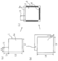
正極活物質としてのLiCoO2を90質量%と、導電剤としてのカーボンブラックを5質量%と、結着剤としてのポリフッ化ビニリデンを5質量%と、溶剤としてのN-メチル-2-ピロリドン(NMP)溶液とを混合して正極用スラリーを調製した。この正極用スラリーを、正極集電体としてのアルミニウム箔(厚み:15μm)の両面に塗布した。その後、加熱することにより溶剤を除去し、ローラーで厚み0.1mmにまで圧縮した後、図1(a)に示すように、幅L1=85mm、高さL2=85mmになるように切断して、両面に正極活物質層1aを有する正極板1を作製した。この際、正極板1における幅L1方向に延びる一辺の一方端部(図1(a)では左端部)から幅L3=30mm、高さL4=20mmの活物質未塗布部を延出させて正極集電リード11とした。
正極活物質としてのLiCoO2を90質量%と、導電剤としてのカーボンブラックを5質量%と、結着剤としてのポリフッ化ビニリデンを5質量%と、溶剤としてのN-メチル-2-ピロリドン(NMP)溶液とを混合して正極用スラリーを調製した。この正極用スラリーを、正極集電体としてのアルミニウム箔(厚み:15μm)の両面に塗布した。その後、加熱することにより溶剤を除去し、ローラーで厚み0.1mmにまで圧縮した後、図1(a)に示すように、幅L1=85mm、高さL2=85mmになるように切断して、両面に正極活物質層1aを有する正極板1を作製した。この際、正極板1における幅L1方向に延びる一辺の一方端部(図1(a)では左端部)から幅L3=30mm、高さL4=20mmの活物質未塗布部を延出させて正極集電リード11とした。
〔負極の作製〕
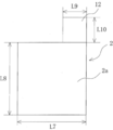
負極活物質としての黒鉛粉末を96質量%と、結着剤としてのカルボキシメチルセルロース(CMC)およびスチレンブタジエンゴム(SBR)をそれぞれ2質量%と、溶剤としての純水とを混合して負極用スラリーを調製した。この負極用スラリーを負極集電体としての銅箔(厚み:10μm)の両面に塗布した。その後、加熱することにより溶剤を除去し、ローラーで厚み0.08mmにまで圧縮した後、図2に示すように、幅L7=90mm、高さL8=90mmになるように切断して、両面に負極活物質層2aを有する負極板2を作製した。この際、負極板2の幅L7方向に延びる一辺において上記正極板1の正極集電リード11形成側端部と反対側となる端部(図2では右端部)から幅L9=30mm、高さL10=20mmの活物質未塗布部を延出させて負極集電リード12とした。
負極活物質としての黒鉛粉末を96質量%と、結着剤としてのカルボキシメチルセルロース(CMC)およびスチレンブタジエンゴム(SBR)をそれぞれ2質量%と、溶剤としての純水とを混合して負極用スラリーを調製した。この負極用スラリーを負極集電体としての銅箔(厚み:10μm)の両面に塗布した。その後、加熱することにより溶剤を除去し、ローラーで厚み0.08mmにまで圧縮した後、図2に示すように、幅L7=90mm、高さL8=90mmになるように切断して、両面に負極活物質層2aを有する負極板2を作製した。この際、負極板2の幅L7方向に延びる一辺において上記正極板1の正極集電リード11形成側端部と反対側となる端部(図2では右端部)から幅L9=30mm、高さL10=20mmの活物質未塗布部を延出させて負極集電リード12とした。
〔正極板が内部に配置された袋状セパレータの作製〕
図1(b)に示すように、幅L5=90mmおよび高さL6=94mmを有する2枚の方形状のポリプロピレン(PP)製のセパレータ3a(厚み30μm)の間に正極板1を配置した後、図1(c)に示すように、セパレータ3aにおいて正極集電リード11が突出する辺以外の3辺を融着部4で熱溶着して、正極板1が内部に収納・配置された袋状セパレータ3を作製した。
図1(b)に示すように、幅L5=90mmおよび高さL6=94mmを有する2枚の方形状のポリプロピレン(PP)製のセパレータ3a(厚み30μm)の間に正極板1を配置した後、図1(c)に示すように、セパレータ3aにおいて正極集電リード11が突出する辺以外の3辺を融着部4で熱溶着して、正極板1が内部に収納・配置された袋状セパレータ3を作製した。
上記セパレータ3aは上述のように高さL6が94mmと、負極板2の高さL8=90mmよりも4mm大きく成形され、したがってそのぶん袋状セパレータ3から正極集電リード11が突出する方向にセパレータ3aが負極板2よりも大きく延出するようになっている。これにより、負極板2の位置ズレによる短絡が生じ難いようになっている。
このとき、正極板1の正極集電リード11における基端部(根元部分)の両面に、絶縁性の樹脂を塗工して、負極板2がセパレータ3aよりも外側にはみ出した場合等に正極集電リード11の基端部(根元部分)と接触して短絡することを防止する絶縁層を形成しておくようにした(図示省略)。
〔積層電極体の作製〕
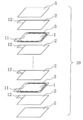
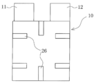
上記正極板1が内部に配置された袋状セパレータ3を35枚、負極板2を36枚調製し、図3に示すように、該袋状セパレータ3と負極板2とを交互に積層した。その際、積層方向における両端部に負極板2が位置するようにし、さらにその両外側に、セパレータ3aと同寸法、同形状のポリプロピレン(PP)製の絶縁シート5をそれぞれ配置するようにした。ついで、図4に示すように、この積層体の両端面を形状保持のための絶縁テープ26で接続して、積層電極体10を得た。この積層電極体10の積層厚さは8.5mmである。
上記正極板1が内部に配置された袋状セパレータ3を35枚、負極板2を36枚調製し、図3に示すように、該袋状セパレータ3と負極板2とを交互に積層した。その際、積層方向における両端部に負極板2が位置するようにし、さらにその両外側に、セパレータ3aと同寸法、同形状のポリプロピレン(PP)製の絶縁シート5をそれぞれ配置するようにした。ついで、図4に示すように、この積層体の両端面を形状保持のための絶縁テープ26で接続して、積層電極体10を得た。この積層電極体10の積層厚さは8.5mmである。
〔集電部の整形・接続〕
以下のa)~e)の手順に従い、上記積層電極体10における正負極集電リード11、12の整形(集束、切断、折り曲げ等)および正負極集電端子15、16との接続を行った。なお、以下の記述、ならびに工程を摸式的に示す図5ないし図9においては、基本的に正極側(正極集電リード11および正極集電端子15)の場合を示すが、これと同時に負極側においても同様に行っている。
以下のa)~e)の手順に従い、上記積層電極体10における正負極集電リード11、12の整形(集束、切断、折り曲げ等)および正負極集電端子15、16との接続を行った。なお、以下の記述、ならびに工程を摸式的に示す図5ないし図9においては、基本的に正極側(正極集電リード11および正極集電端子15)の場合を示すが、これと同時に負極側においても同様に行っている。
a)第1ステップ(正負極集電リードの集束および切断)
図5に示すように、積層電極体10をワーク押え41により矢印A11に示すように上下から挟圧するようにして保持しながら、積層された正極集電リード11を、矢印A12に示すように上方から集束ヘッド42でまとめて押し下げるようにして、積層電極体10の積層方向における一方の最外面側(図5では下面側)に寄せるようにして基端部に集束した。ついで、この正極集電リード11の集束部B11から先端側へ延びる部位における余剰部を、積層電極体10から距離7.5mmをおいた切断位置C11で切断して先端を揃えた。即ち、切断後の正極集電リード11の積層電極体10からの延出長さは7.5mmである。
図5に示すように、積層電極体10をワーク押え41により矢印A11に示すように上下から挟圧するようにして保持しながら、積層された正極集電リード11を、矢印A12に示すように上方から集束ヘッド42でまとめて押し下げるようにして、積層電極体10の積層方向における一方の最外面側(図5では下面側)に寄せるようにして基端部に集束した。ついで、この正極集電リード11の集束部B11から先端側へ延びる部位における余剰部を、積層電極体10から距離7.5mmをおいた切断位置C11で切断して先端を揃えた。即ち、切断後の正極集電リード11の積層電極体10からの延出長さは7.5mmである。
なお、図5に示す参照符号32は、前述の、正極板1の正極集電リード11における基端部(根元部分)の両面に形成した絶縁層を指示する。
b)第2ステップ(正負極集電端子の接続)
図6に示すように、正極集電リード11の集束部B11から先端側へ延びる部位に下方から正極集電端子15の正負極板1、2側4mmの部分を重ねるように配置し、この状態で上下から超音波ホーン43Tおよびアンビル43Bをセットして超音波溶接を行った。
図6に示すように、正極集電リード11の集束部B11から先端側へ延びる部位に下方から正極集電端子15の正負極板1、2側4mmの部分を重ねるように配置し、この状態で上下から超音波ホーン43Tおよびアンビル43Bをセットして超音波溶接を行った。
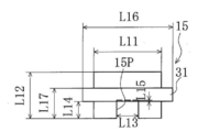
正極集電端子15は、厚み0.4mmのアルミニウム板を、図10に示すように、幅L11=30mm、高さL12=20.5mmの矩形状であって、一方長辺(図10では下辺)の中央に、幅L13=10mm、深さL14+L15=8.0mmの矩形状に凹入する切欠状の貫通部15Pを有する形状(図10では逆凹字形状)となるように成形して作製した。正極集電端子15における高さL12方向中央あたりの高さ位置には、正極集電端子15の幅L11方向に沿って延びる長さL16=40mm、高さ(幅)L17-L14=6.0mmの帯状となるように樹脂封止材(糊材)を固着し、後述する外装体18を熱封止する際の密閉性を確保するための端子シール部31を形成した。またこのとき、貫通部15Pの内奥端から深さL15=0.5mmの領域に端子シール部31が重複するように、即ち貫通部15Pの内奥端から深さL15=0.5mmの領域が端子シール部31により覆われるようにした。
なお、上記した以外にも、図10における各部の寸法は以下の通りとなっている。
・正極集電端子15における貫通部15P形成側端縁(図10では下端縁)から、端子シール部31の一方端縁(図10では下端縁)までの距離L14=7.5mm
・正極集電端子15における貫通部15P形成側端縁(図10では下端縁)から、端子シール部31の他方端縁(図10では上端縁)までの距離、即ち正極集電端子15における貫通部15P形成側端縁から端子シール部31形成領域までを含む領域の高さL17=13.5mm
なお、上記した以外にも、図10における各部の寸法は以下の通りとなっている。
・正極集電端子15における貫通部15P形成側端縁(図10では下端縁)から、端子シール部31の一方端縁(図10では下端縁)までの距離L14=7.5mm
・正極集電端子15における貫通部15P形成側端縁(図10では下端縁)から、端子シール部31の他方端縁(図10では上端縁)までの距離、即ち正極集電端子15における貫通部15P形成側端縁から端子シール部31形成領域までを含む領域の高さL17=13.5mm
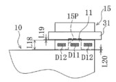
正極集電端子15の接続のより具体的な手順としては、図11に示すように、正極集電端子15における貫通部15P形成端部(先端からL18=7mmの部分)の上に、正極集電リード11の集束部B11より先端の部分を重ねた状態で、まず、貫通部15Pが形成された領域内の第1溶接点D11で、積層された35枚の正極集電リード11同士のみを超音波溶接により接合し、ついで、貫通部15Pが形成された領域の両側に隣接する領域内の第2溶接点D12で、積層された35枚の正極集電リード11と正極集電端子15とを超音波溶接により接合した。
なお、正極集電リード11の先端と端子シール部31との間の距離L19は0.5mm、正極集電端子15における貫通部15P形成側端と積層電極体10との間の距離L20は0.5mmである。
なお、正極集電リード11の先端と端子シール部31との間の距離L19は0.5mm、正極集電端子15における貫通部15P形成側端と積層電極体10との間の距離L20は0.5mmである。
上記第1溶接点D11はリード限定接合部となっており、第2溶接点D12はリード-端子接合部となっているが、これらリード限定接合部(第1溶接点D11)とリード-端子接合部(第2溶接点D12)とは、正極集電リード11の延出方向に対し垂直な方向に沿って一直線上に並ぶ位置関係となっている。
一方、負極集電端子16(図5ないし図11では図示せず)については、材料として銅板を用いた点以外は、上述の正極集電端子15の場合と同様にして、作製および接続を行った。
上記正負極集電端子の接続工程における溶接条件を下記表1に示す。

c)第3ステップ(絶縁層の形成)
図7に示すように、正極集電リード11と正極集電端子15との接合部(以下、「正極集電接合部」とも称す)F11における一方側面である正極集電リード11側面(図7では上側面)に30mm×5mm×厚み35μmのポリイミド製の絶縁テープ44Nを付着して絶縁層(以下、「内側絶縁層44N」とも称す)を形成し、他方側面である正極集電端子15側面(図7では下側面)に30mm×12mm×厚み70μmのポリイミド製の絶縁テープ44Eを付着して絶縁層(以下、「外側絶縁層44E」とも称す)を形成した。
図7に示すように、正極集電リード11と正極集電端子15との接合部(以下、「正極集電接合部」とも称す)F11における一方側面である正極集電リード11側面(図7では上側面)に30mm×5mm×厚み35μmのポリイミド製の絶縁テープ44Nを付着して絶縁層(以下、「内側絶縁層44N」とも称す)を形成し、他方側面である正極集電端子15側面(図7では下側面)に30mm×12mm×厚み70μmのポリイミド製の絶縁テープ44Eを付着して絶縁層(以下、「外側絶縁層44E」とも称す)を形成した。
このとき、内側絶縁層44Nとなる絶縁テープ44Nは、正極集電リード11の集束部B11近傍から、先端より若干外側までを覆うように貼着し、外側絶縁層44Eとなる絶縁テープ44Eにおける正負極板1、2側(正極集電リード11の基端部側)は、積層電極体10の積層方向における一方側面(即ち図5では下側の絶縁シート5の下面)の先端縁部にやや重なるように貼着し、集電部引き出し側(正極集電リード11の先端側)は、正極集電端子15および端子シール部31の端部に重なるように貼着した。これにより、正極集電接合部F11における一方側面である正極集電リード11側面(図7では上側面)の金属部分は内側絶縁層44Nとなる絶縁テープ44Nによりほぼ全面的に覆う。また、他方側面である正極集電端子15側面(図7では下側面)は積層電極体10の絶縁シート5と正極集電端子15の端子シール部31との間を全面的に覆って金属部分が露出しないようにした。
d)第4ステップ(正負極集電端子の折り曲げ)
図8に示すように、正極集電接合部F11を上下から押え具45T、45Bで押圧するように保持固定しながら、正極集電端子15において正極集電接合部F11よりも先端側に突出する部分、即ち正極集電端子15における正負極板1、2側端(積層電極体10側端)から7mmの位置よりも集電部引き出し側(先端側)へ延びる部分を、矢印A13に示すように側面視鉤形状(L形状)となるように外側(図8では下側)へ折り曲げた。このとき、正極集電端子15の折り曲げ線は、端子シール部31の積層電極体10側端と実質的に同等の位置(厳密には、折り曲げが十分に可能となるように、端子シール部31の積層電極体10側端よりも僅かに、即ち正極集電端子15の厚みぶん程度、積層電極体10寄りの位置)となっている。
図8に示すように、正極集電接合部F11を上下から押え具45T、45Bで押圧するように保持固定しながら、正極集電端子15において正極集電接合部F11よりも先端側に突出する部分、即ち正極集電端子15における正負極板1、2側端(積層電極体10側端)から7mmの位置よりも集電部引き出し側(先端側)へ延びる部分を、矢印A13に示すように側面視鉤形状(L形状)となるように外側(図8では下側)へ折り曲げた。このとき、正極集電端子15の折り曲げ線は、端子シール部31の積層電極体10側端と実質的に同等の位置(厳密には、折り曲げが十分に可能となるように、端子シール部31の積層電極体10側端よりも僅かに、即ち正極集電端子15の厚みぶん程度、積層電極体10寄りの位置)となっている。
e)第5ステップ(正負極集電接合部の折り曲げおよび位置決め)
図9および図12~図14に示すように、正極集電接合部F11が積層電極体10の積層方向(図9では上下方向)に略平行となるように、正極集電接合部F11よりも正負極板1、2側部(正極集電リード11の基端部)で、矢印A14に示すように内側(図9では上側)へ折り曲げた。なお、図12ないし図14では、内側絶縁層(絶縁テープ)44Nおよび外側絶縁層(絶縁テープ)44Eは省略している。
図9および図12~図14に示すように、正極集電接合部F11が積層電極体10の積層方向(図9では上下方向)に略平行となるように、正極集電接合部F11よりも正負極板1、2側部(正極集電リード11の基端部)で、矢印A14に示すように内側(図9では上側)へ折り曲げた。なお、図12ないし図14では、内側絶縁層(絶縁テープ)44Nおよび外側絶縁層(絶縁テープ)44Eは省略している。
ついで、図9に示すように、正極集電端子15と積層電極体10との間に架設するように、30mm×10mm×厚み35μmのポリイミド製の絶縁テープ(以下「係留テープ」とも称す)46を正極集電接合部F11の先端側方向(図9では上方)から付着し、これにより、正極集電リード11を所定の折り曲げ状態に保持して位置決めした。
このとき、厚い金属板よりなる正極集電端子15が存在する正極集電接合部F11およびこれより先端側を、正極集電接合部F11と正負極板1、2との間(即ち集束部B11ないしその近傍)において積層状態の金属箔よりなる正極集電リード11のみが存在する位置で折り曲げるので、正極集電接合部F11およびこれより先端側を正極集電端子15ごと容易に折り曲げることができる。
またこのとき、係留テープ46における正負極板1、2側(正極集電リード11の基端部側)は、積層電極体10の積層方向における他方側面(即ち図9では上側の絶縁シート5の上面)の先端縁部にやや重なるように貼着し、係留テープ46における集電部引き出し側(正極集電リード11の延出方向先端側)は、正極集電端子15および端子シール部31の端部に重なるように貼着した。これにより、正極集電接合部F11の先端側部(図9では上部)において、積層電極体10の絶縁シート5と正極集電端子15の端子シール部31との間を全面的に覆って金属部分が露出しないようにした。
〔外装体への封入〕
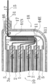
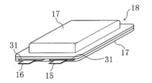
図15および図16に示すように、あらかじめ電極体が設置できるように成形したラミネートフィルム17で構成した外装体18に、上記積層電極体10を挿入し、正極集電端子15および負極集電端子16のみが外装体18より外部に突出するようにして、正極集電端子15および負極集電端子16がある辺を除く1辺を残し、熱融着した。
図15および図16に示すように、あらかじめ電極体が設置できるように成形したラミネートフィルム17で構成した外装体18に、上記積層電極体10を挿入し、正極集電端子15および負極集電端子16のみが外装体18より外部に突出するようにして、正極集電端子15および負極集電端子16がある辺を除く1辺を残し、熱融着した。
〔電解液の封入、密封化〕
上記外装体18の熱溶着していない1辺から、エチレンカーボネート(EC)とメチルエチルカーボネート(MEC)とが体積比で30:70の割合で混合された混合溶媒に、LiPF6が1M(モル/リットル)の割合で溶解された電解液を注入した。最後に外装体18における熱溶着していない1辺を減圧状態で熱溶着して、電池(以下、「本発明電池」と称す)A1を作製した。
上記外装体18の熱溶着していない1辺から、エチレンカーボネート(EC)とメチルエチルカーボネート(MEC)とが体積比で30:70の割合で混合された混合溶媒に、LiPF6が1M(モル/リットル)の割合で溶解された電解液を注入した。最後に外装体18における熱溶着していない1辺を減圧状態で熱溶着して、電池(以下、「本発明電池」と称す)A1を作製した。
<本発明電池A1の基本的特徴およびその効果>
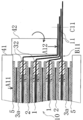
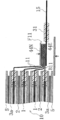
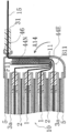
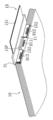
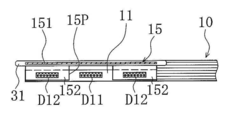
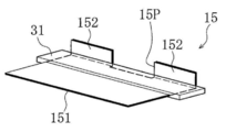
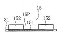
以上の記述から明らかなように、上記本発明電池A1においては、図17ないし図20に示すように、正極集電端子15が、積層電極体10における正負極板1、2と実質的に平行な第1片151と、積層電極体10における正負極板1、2の積層方向と実質的に平行な第2片152とを有するように折り曲げて側面視鉤形状(L形状)に成形され、第1片151から第2片152にかけて拡がる貫通部15Pが形成された構成となっている。そして、図12および図13に示すように、正極集電リード11が、正極集電端子15の第2片152に第2溶接点D12で接合されるとともに、貫通部15Pが形成された領域内の第1溶接点D11で、積層された正極集電リード11同士が接合されている。一方、負極集電端子16は、材料が銅板である点以外は上記正極集電端子15と同様の構成を有し、また、上記正極集電端子15と正極集電リード11とを接続する場合と同様にして、負極集電端子16と負極集電リード12とが接続されている。
なお、図20に示す、正極集電端子15における第1片151の長さ(第1片151と第2片152との境界すなわち折り曲げ位置から第1片151が延出する長さ)L21は13.5mm、第2片152の長さ(第1片151と第2片152との境界すなわち折り曲げ位置から第2片152が延出する長さ)L22は7.3mmである。
上記本発明電池A1の構成によれば、正極集電部の場合を代表的に取り上げると、貫通部15Pが形成された領域、即ち正極集電端子15が存在しない領域で、積層された正極集電リード11同士が接合されていることで閉回路が形成され、これにより接続抵抗が均一化されている。したがって、ハイレートでの充放電時にも各正極板1に流れ込む電流値にバラツキが生じることもなく、良好なサイクル特性を得ることができるようになっている。また、貫通部15Pが形成された領域で接合がなされるので、接合部の面積の増大も回避されており、体積エネルギー密度も良好に維持されている。
このとき、貫通部15Pが、正極集電端子15における第1片151から第2片152にかけて拡がるように形成されているので、折り曲げ成形時における正極集電端子15の変形が効果的に抑制されるようになっている。貫通部15Pおよび側面視鉤形状(L字形状)の折曲形状を・BR>Lする図17ないし図20に示すような正極集電端子15を成形する場合、折り曲げ成形を行った後では貫通部15Pが形成し難いため、折り曲げ成形を行う前に、アルミニウム板から切り出す工程で正極集電端子15に貫通部15Pを予め形成しておくようにしている。このとき、例えば貫通部15Pが形成された領域以外の領域すなわち貫通部15Pが形成されていない領域で折り曲げるようにすると、折り曲げの応力により、貫通部15Pの端部(例えば入隅部等)が変形し易い。このような変形が生じると、この変形部がラミネート外装体18の内側絶縁層を突き破ってラミネート外装体18の金属層と接触するといった問題がある。この問題を回避するため、例えば折り曲げの応力が伝わらない程度に貫通部15Pから距離をおいた位置で正極集電端子15を折り曲げることも考えられるが、これによれば貫通部15Pと折り曲げ位置との距離の増大により電池体積上のロスすなわち体積エネルギー密度のロスを生じることとなる。これに対し、上記本発明電池A1の構成によれば、貫通部15Pが、正極集電端子15における第1片151から第2片152にかけて拡がるように形成されており、したがって貫通部15Pが形成された位置で正極集電端子15が折り曲げられるようになっているので、折り曲げの応力が小さくなっていて折り曲げ部以外には作用し難くなっている。これにより、体積エネルギー密度のロスを生じることもなく、折り曲げ部以外での正極集電端子15の無用な変形が効果的に抑制されるようになっている。
〔その他の事項〕
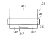
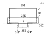
(1)上記本発明電池A1においては、正極集電端子15に矩形状に内側へ凹入する貫通部(以下、凹入貫通部とも称す)15Pが形成されているが、貫通部としてはこれ以外にも、例えば図21に示すような孔(開口)状の貫通部(以下、孔状貫通部とも称す)34P、図22に示すような角落ち状の貫通部(以下、角落状貫通部とも称す)35P等も可能である。
(1)上記本発明電池A1においては、正極集電端子15に矩形状に内側へ凹入する貫通部(以下、凹入貫通部とも称す)15Pが形成されているが、貫通部としてはこれ以外にも、例えば図21に示すような孔(開口)状の貫通部(以下、孔状貫通部とも称す)34P、図22に示すような角落ち状の貫通部(以下、角落状貫通部とも称す)35P等も可能である。
図21に示す孔状貫通部34Pは、集電端子34における一端縁部の中央に、矩形状(横長の長方形状)の孔(開口)を穿設することにより形成されている。この孔状貫通部34Pが形成された集電端子34には、上記凹入貫通部15Pが形成された本発明電池A1の正極集電端子15の場合と全く同様にして極板リードが接合される。
この場合、孔状貫通部34P形成領域において複数枚の極板リードのみが第1の接合点で接合されるとともに、この孔状貫通部34P形成領域の側方に隣接する領域すなわち極板リードの延出方向に対し垂直な方向(幅方向)に並ぶように隣接する領域において極板リードが集電端子34に第2の接合点でそれぞれ接合される。
この場合、孔状貫通部34P形成領域において複数枚の極板リードのみが第1の接合点で接合されるとともに、この孔状貫通部34P形成領域の側方に隣接する領域すなわち極板リードの延出方向に対し垂直な方向(幅方向)に並ぶように隣接する領域において極板リードが集電端子34に第2の接合点でそれぞれ接合される。
図22に示す角落状貫通部35Pは、集電端子35における一端縁部の両端部すなわち隣り合う1組の角部を矩形状(横長の長方形状)に切欠くようにして角落ちさせることにより形成されている。この角落状貫通部35Pが形成された集電端子35に極板リードを接合する場合には、両側の角落状貫通部35Pの間に形成された中央の突起部35Eに第2の接合点が位置し、該第2の接合点に対し幅方向に沿って両側に隣り合う角落状貫通部35P内に第1の接合点が位置することとなり、両側の第1の接合点で接合を行った後、中央の第2の接合点で接合を行うようにする。
即ちこの場合、角落状貫通部35P形成領域において複数枚の極板リードのみが第1の接合点でそれぞれ接合されるとともに、両側の角落状貫通部35P形成領域に対し中央側に隣接する領域すなわち極板リードの延出方向に対し垂直な方向(幅方向)に並ぶように隣接する領域である中央の突起部35Eにおいて極板リードが集電端子35に第2の接合点で接合される。
即ちこの場合、角落状貫通部35P形成領域において複数枚の極板リードのみが第1の接合点でそれぞれ接合されるとともに、両側の角落状貫通部35P形成領域に対し中央側に隣接する領域すなわち極板リードの延出方向に対し垂直な方向(幅方向)に並ぶように隣接する領域である中央の突起部35Eにおいて極板リードが集電端子35に第2の接合点で接合される。
上記凹入貫通部15P、孔状貫通部34Pおよび角落状貫通部35Pのいずれの場合にも、第2の接合点では厚い集電端子と極板リードとが接合されるため、先にこの第2の接合点で接合を行うと第1の接合点で極板リードのみを接合することが困難となるので、まず第1の接合点で極板リードのみを接合してから、第2の接合点で集電端子と極板リードとを接合するようにする。
上記凹入貫通部15P、孔状貫通部34Pおよび角落状貫通部35Pのうち、接合の容易性の点では、凹入貫通部15Pと角落状貫通部35Pとがほぼ同等であり、これに比して孔状貫通部34Pがやや劣るものとなっている。また、形成の容易性(加工性)の点では、凹入貫通部15P、角落状貫通部35P、孔状貫通部34Pの順で優れるものとなっている。
上記孔状貫通部34Pおよび角落状貫通部35Pは、図21および図22に示すように、本発明電池A1における凹入貫通部15Pの場合と同様に、内奥端部が端子シール部31に重複するように、即ち内奥端部が端子シール部31により覆われるように形成されている。また、図21および図22には、展開状態の集電端子34、35が示されているが、それぞれ、端子シール部31の積層電極体10側端(図21および図22では下端)と実質的に同等の位置にある折り曲げ線G11、G12で折り曲げられ、この折り曲げ線G11、G12よりも端子シール部31側(図21および図22では上側)が第1片341、351、折り曲げ線G11、G12よりも積層電極体10側(図21および図22では下側)が第2片342、352となる。
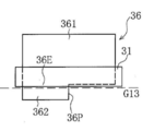
(2)上記凹入貫通部15P、孔状貫通部34Pおよび角落状貫通部35Pの構成では、1箇所または2箇所の貫通部形成領域と、これに隣接する2箇所または1箇所の貫通部不形成領域との、計3領域が幅方向に1列に並ぶように配置されるが、例えば図23に示すように、貫通部形成領域と貫通部不形成領域とが1箇所ずつ、計2領域が幅方向に並ぶように配置される構成としてもよい。同図に示す例では、集電端子36における一端縁部の一方側半部を矩形状(横長の長方形状)に切欠くようにして貫通部36Pが形成され、該貫通部36Pに隣接して突起部36Eが形成されて、当該端部が全体として鉤形状に成形されており、貫通部36P内に第1の接合点が位置し、該第1の接合点に対し幅方向に沿って側方に隣り合うように、突起部36E上に第2の接合点が位置するようになっている。この構成によれば、溶接点数を削減することができるが、貫通部形成領域(第1の接合点)および貫通部不形成領域(第2の接合点)の配置が左右非対称となって偏りが生じる難点がある。これに対し、上記凹入貫通部15P、孔状貫通部34Pおよび角落状貫通部35Pの構成ではいずれも、貫通部形成領域と貫通部不形成領域とが左右対称に配置されるため、バランスの点でより好ましい。
図23に示すように、上記貫通部形成領域と貫通部不形成領域とが1箇所ずつ形成された(非対称型の)集電端子36の貫通部36Pも、前記孔状貫通部34Pおよび角落状貫通部35Pの場合と同様に、内奥端部が端子シール部31に重複するように、即ち内奥端部が端子シール部31により覆われるように形成されている。また、集電端子36が、端子シール部31の積層電極体10側端(図23では下端)と実質的に同等の位置にある折り曲げ線G13で折り曲げられ、この折り曲げ線G13よりも端子シール部31側(図23では上側)が第1片361、折り曲げ線G13よりも積層電極体10側(図23では下側)が第2片362となる。
(3)上記本発明電池A1においては、正極集電端子15をアルミニウム板、負極集電端子16を銅板でそれぞれ構成しているが、これらをニッケル板で構成しても良い。このように両集電端子に同一素材のものを用いれば、電池の生産コストが低減できる。またこの場合、異種金属同士(なぜなら、正極集電リード11はアルミニウム、負極集電リード12は銅から構成されている)の溶接となるため、溶接部の溶着性が悪くなり、両極板と両端子との間の接続抵抗値にバラツキを生じるという問題が一層顕在化するので、本発明の構成が特に有用となる。
(4)外装体としては、例えば電池缶等を用いるようにしてもよいが、フィルム外装体を用いるほうが、正負極集電端子に折り曲げによる変形が生じた場合に外装体が損傷しやすいといった問題があることから、本発明の効果が特に発揮される。さらに、フィルム外装体のうち、ラミネートフィルムより構成されるラミネート外装体を用いるほうが、正負極集電端子に折り曲げによる変形が生じた場合に短絡を生じやすいといった問題があるため、本発明の構成がいっそう有用となる。
ラミネート外装体としては、例えば、
金属層としてアルミニウム、アルミニウム合金、ステンレス等を、
内層(電池内側)としてポリエチレン、ポリプロピレン等を、
外層(電池外側)としてナイロン、ポリエチレンテレフタレート(PET)、PET/ナイロンの積層膜等を、
それぞれ用いて構成されるものが挙げられる。
金属層としてアルミニウム、アルミニウム合金、ステンレス等を、
内層(電池内側)としてポリエチレン、ポリプロピレン等を、
外層(電池外側)としてナイロン、ポリエチレンテレフタレート(PET)、PET/ナイロンの積層膜等を、
それぞれ用いて構成されるものが挙げられる。
(5)正極活物質としては、上記コバルト酸リチウムに限定されるものではなく、コバルト-ニッケル-マンガン、アルミニウム-ニッケル-マンガン、アルミニウム-ニッケル-コバルト等のコバルト、ニッケル或いはマンガンを含むリチウム複合酸化物や、スピネル型マンガン酸リチウム等でも構わない。
(6)負極活物質としては、天然黒鉛、人造黒鉛等の黒鉛以外にも、グラファイト・コークス・酸化スズ・金属リチウム・珪素・及びそれらの混合物等、リチウムイオンを挿入脱離できうるものであれば構わない。
(7)電解液としても特に本実施例で示したものに限定されるものではなく、リチウム塩としては例えばLiBF4、LiPF6、LiN(SO2CF3)2,LiN(SO2C2F5)2,LiPF6―x(CnF2n+1)x[但し、1<x<6、n=1又は2]等が挙げられ、これらの1種もしくは2種以上を混合して使用できる。支持塩の濃度は特に限定されないが、電解液1リットル当り0.8~1.8モルが望ましい。また、溶媒種としては上記ECやMEC以外にも、プロピレンカーボネート(PC)、γ-ブチロラクトン(GBL)、エチルメチルカーボネート(EMC)、ジメチルカーボネート(DMC)、ジエチルカーボネート(DEC)等のカーボネート系溶媒が好ましく、更に好ましくは環状カーボネートと鎖状カーボネートの組合せが望ましい。
本発明は、例えばロボットや電気自動車等に搭載される動力、バックアップ電源などの高出力用途の電源に好適に適用することができる。
10 積層電極体
11 正極集電リード
15 正極集電端子
151 第1片
152 第2片
15P 貫通部
D11 第1溶接点
D12 第2溶接点
11 正極集電リード
15 正極集電端子
151 第1片
152 第2片
15P 貫通部
D11 第1溶接点
D12 第2溶接点
Claims (4)
- 複数枚の正極板と負極板とがセパレータを介して交互に積層され、該正極板および負極板から延出した正極集電リードおよび負極集電リードが正極集電端子および負極集電端子にそれぞれ複数枚積層して接合された構成を有する積層電極体を備える積層式電池であって、
前記正極集電端子および負極集電端子の少なくとも一方が、前記積層電極体における正極板および負極板と実質的に平行な第1片と、前記積層電極体における正極板および負極板の積層方向と実質的に平行な第2片とを有するように折り曲げ成形され、
前記正極集電端子および負極集電端子の少なくとも一方における第1片から第2片にかけて拡がる貫通部が形成され、
前記正極集電リードおよび負極集電リードの少なくとも一方が、前記正極集電端子および負極集電端子の少なくとも一方における第2片に接合されるとともに、前記貫通部が形成された領域で、積層された正極集電リード同士および/または負極集電リード同士が接合されていることを特徴とする積層式電池。 - 前記正極集電リードおよび負極集電リードの少なくとも一方が、前記正極集電端子および負極集電端子の少なくとも一方における第2片に接合される接合部と、前記貫通部が形成された領域で、積層された正極集電リード同士および/または負極集電リード同士が接合される接合部とが、正極集電リードまたは負極集電リードの延出方向に対し実質的に垂直な方向に沿って並んでいる、請求項1に記載の積層式電池。
- 前記正極集電端子および負極集電端子に、外装体を封止する際の密閉性を確保するための樹脂封止材が付着され、該樹脂封止材が、前記貫通部が形成された領域に重複するように付着されている、請求項1または請求項2に記載の積層式電池。
- 前記樹脂封止材の積層電極体側端が、前記正極集電端子および/または負極集電端子の折り曲げ線の位置にくるように配置されている、請求項3に記載の積層式電池。
Applications Claiming Priority (2)
| Application Number | Priority Date | Filing Date | Title |
|---|---|---|---|
| JP2011041627A JP2014102875A (ja) | 2011-02-28 | 2011-02-28 | 積層式電池 |
| JP2011-041627 | 2011-02-28 |
Publications (1)
| Publication Number | Publication Date |
|---|---|
| WO2012117883A1 true WO2012117883A1 (ja) | 2012-09-07 |
Family
ID=46757822
Family Applications (1)
| Application Number | Title | Priority Date | Filing Date |
|---|---|---|---|
| PCT/JP2012/054060 Ceased WO2012117883A1 (ja) | 2011-02-28 | 2012-02-21 | 積層式電池 |
Country Status (2)
| Country | Link |
|---|---|
| JP (1) | JP2014102875A (ja) |
| WO (1) | WO2012117883A1 (ja) |
Cited By (4)
| Publication number | Priority date | Publication date | Assignee | Title |
|---|---|---|---|---|
| JP2013161686A (ja) * | 2012-02-06 | 2013-08-19 | Toyota Industries Corp | 蓄電装置、及び車両 |
| WO2014050988A1 (ja) * | 2012-09-27 | 2014-04-03 | Necエナジーデバイス株式会社 | リチウムイオン二次電池及びその製造方法 |
| CN110380098A (zh) * | 2018-04-12 | 2019-10-25 | 丰田自动车株式会社 | 电池的制造方法和电池 |
| CN111384354A (zh) * | 2018-12-27 | 2020-07-07 | 三洋电机株式会社 | 二次电池 |
Families Citing this family (4)
| Publication number | Priority date | Publication date | Assignee | Title |
|---|---|---|---|---|
| KR101736548B1 (ko) | 2014-11-19 | 2017-05-16 | 주식회사 엘지화학 | 이차전지의 복수개의 전극 탭과 전극 리드의 용접 방법 및 이에 의해 제조된 이차 전지, 이차전지의 복수개의 전극 탭과 전극 리드의 용접 불량 검사 방법 |
| JP2018181622A (ja) * | 2017-04-14 | 2018-11-15 | 株式会社日立製作所 | 積層型二次電池 |
| JP7463930B2 (ja) | 2020-09-30 | 2024-04-09 | トヨタ自動車株式会社 | 電池 |
| DE102023203411A1 (de) * | 2023-04-14 | 2024-10-17 | Volkswagen Aktiengesellschaft | Batteriezelle mit einer Elektrodenableiter-Isolierung |
Citations (7)
| Publication number | Priority date | Publication date | Assignee | Title |
|---|---|---|---|---|
| JPH1125951A (ja) * | 1997-07-07 | 1999-01-29 | Sanyo Electric Co Ltd | 電 池 |
| JP2005340689A (ja) * | 2004-05-31 | 2005-12-08 | Tdk Corp | 電気化学デバイス、その製造方法、及び当該デバイス用いられる電極 |
| JP2007227090A (ja) * | 2006-02-22 | 2007-09-06 | Toshiba Corp | 非水電解質電池、電池パック及び自動車 |
| JP2007234466A (ja) * | 2006-03-02 | 2007-09-13 | Nec Tokin Corp | 積層型リチウムイオン電池およびその製造方法 |
| JP2008066170A (ja) * | 2006-09-08 | 2008-03-21 | Nec Tokin Corp | 積層型電池の製造方法 |
| JP2008091268A (ja) * | 2006-10-04 | 2008-04-17 | Nissan Motor Co Ltd | 薄型電池 |
| JP2009048806A (ja) * | 2007-08-15 | 2009-03-05 | Sony Corp | 非水電解質二次電池 |
-
2011
- 2011-02-28 JP JP2011041627A patent/JP2014102875A/ja not_active Withdrawn
-
2012
- 2012-02-21 WO PCT/JP2012/054060 patent/WO2012117883A1/ja not_active Ceased
Patent Citations (7)
| Publication number | Priority date | Publication date | Assignee | Title |
|---|---|---|---|---|
| JPH1125951A (ja) * | 1997-07-07 | 1999-01-29 | Sanyo Electric Co Ltd | 電 池 |
| JP2005340689A (ja) * | 2004-05-31 | 2005-12-08 | Tdk Corp | 電気化学デバイス、その製造方法、及び当該デバイス用いられる電極 |
| JP2007227090A (ja) * | 2006-02-22 | 2007-09-06 | Toshiba Corp | 非水電解質電池、電池パック及び自動車 |
| JP2007234466A (ja) * | 2006-03-02 | 2007-09-13 | Nec Tokin Corp | 積層型リチウムイオン電池およびその製造方法 |
| JP2008066170A (ja) * | 2006-09-08 | 2008-03-21 | Nec Tokin Corp | 積層型電池の製造方法 |
| JP2008091268A (ja) * | 2006-10-04 | 2008-04-17 | Nissan Motor Co Ltd | 薄型電池 |
| JP2009048806A (ja) * | 2007-08-15 | 2009-03-05 | Sony Corp | 非水電解質二次電池 |
Cited By (15)
| Publication number | Priority date | Publication date | Assignee | Title |
|---|---|---|---|---|
| JP2013161686A (ja) * | 2012-02-06 | 2013-08-19 | Toyota Industries Corp | 蓄電装置、及び車両 |
| CN106910941A (zh) * | 2012-09-27 | 2017-06-30 | Nec能源元器件株式会社 | 锂离子二次电池及其制作方法 |
| US10153477B2 (en) | 2012-09-27 | 2018-12-11 | Nec Energy Devices, Ltd. | Lithium-ion secondary battery and method of producing the same |
| JPWO2014050988A1 (ja) * | 2012-09-27 | 2016-08-22 | Necエナジーデバイス株式会社 | リチウムイオン二次電池及びその製造方法 |
| US9570776B2 (en) | 2012-09-27 | 2017-02-14 | Nec Energy Devices, Ltd. | Lithium-ion secondary battery and method of producing the same |
| CN104685701B (zh) * | 2012-09-27 | 2017-03-22 | Nec能源元器件株式会社 | 锂离子二次电池及其制作方法 |
| WO2014050988A1 (ja) * | 2012-09-27 | 2014-04-03 | Necエナジーデバイス株式会社 | リチウムイオン二次電池及びその製造方法 |
| JP2017168462A (ja) * | 2012-09-27 | 2017-09-21 | Necエナジーデバイス株式会社 | リチウムイオン二次電池 |
| CN104685701A (zh) * | 2012-09-27 | 2015-06-03 | Nec能源元器件株式会社 | 锂离子二次电池及其制作方法 |
| CN110380098A (zh) * | 2018-04-12 | 2019-10-25 | 丰田自动车株式会社 | 电池的制造方法和电池 |
| CN110380098B (zh) * | 2018-04-12 | 2022-11-15 | 丰田自动车株式会社 | 电池的制造方法和电池 |
| CN111384354A (zh) * | 2018-12-27 | 2020-07-07 | 三洋电机株式会社 | 二次电池 |
| JP2020107513A (ja) * | 2018-12-27 | 2020-07-09 | 三洋電機株式会社 | 二次電池 |
| JP7300266B2 (ja) | 2018-12-27 | 2023-06-29 | 三洋電機株式会社 | 二次電池 |
| CN111384354B (zh) * | 2018-12-27 | 2024-01-19 | 三洋电机株式会社 | 二次电池 |
Also Published As
| Publication number | Publication date |
|---|---|
| JP2014102875A (ja) | 2014-06-05 |
Similar Documents
| Publication | Publication Date | Title |
|---|---|---|
| JP5474466B2 (ja) | 積層式電池 | |
| JP5844052B2 (ja) | 積層式電池およびその製造方法 | |
| JP6158789B2 (ja) | 積層式電池 | |
| CN101779310B (zh) | 电池 | |
| JP5583421B2 (ja) | 角形密閉二次電池及び角形密閉二次電池の製造方法 | |
| JP5550923B2 (ja) | 角形二次電池の製造方法 | |
| US9406921B2 (en) | Prismatic secondary battery | |
| JP6043428B2 (ja) | 角形電池及び組電池 | |
| JP2012199162A (ja) | ラミネート外装体二次電池 | |
| JP2012054029A (ja) | 積層式電池 | |
| JP2014102875A (ja) | 積層式電池 | |
| JP2011049065A (ja) | 非水電解質電池およびその製造方法 | |
| JP4148458B2 (ja) | 電池 | |
| JP2013178997A (ja) | 二次電池 | |
| JP6757499B2 (ja) | 二次電池 | |
| JP2013080563A (ja) | 積層型二次電池 | |
| CN115732864A (zh) | 电池、电极板的制造方法及电池的制造方法 | |
| JP2010086780A (ja) | 角形二次電池 | |
| JP2012028187A (ja) | 発電要素および二次電池 | |
| US20250087845A1 (en) | Secondary battery and method of manufacturing same | |
| JP2011175913A (ja) | 積層式電池 | |
| JP2010086799A (ja) | 積層型電池 | |
| JP2009110812A (ja) | 電池及びその製造方法 | |
| JP5954339B2 (ja) | 角形二次電池及びその製造方法 | |
| JP7745583B2 (ja) | 蓄電デバイスの製造方法 |
Legal Events
| Date | Code | Title | Description |
|---|---|---|---|
| 121 | Ep: the epo has been informed by wipo that ep was designated in this application |
Ref document number: 12752587 Country of ref document: EP Kind code of ref document: A1 |
|
| NENP | Non-entry into the national phase |
Ref country code: DE |
|
| 122 | Ep: pct application non-entry in european phase |
Ref document number: 12752587 Country of ref document: EP Kind code of ref document: A1 |
|
| NENP | Non-entry into the national phase |
Ref country code: JP |