WO2012114905A1 - Batterie auxiliaire à électrolyte non aqueux - Google Patents
Batterie auxiliaire à électrolyte non aqueux Download PDFInfo
- Publication number
- WO2012114905A1 WO2012114905A1 PCT/JP2012/053074 JP2012053074W WO2012114905A1 WO 2012114905 A1 WO2012114905 A1 WO 2012114905A1 JP 2012053074 W JP2012053074 W JP 2012053074W WO 2012114905 A1 WO2012114905 A1 WO 2012114905A1
- Authority
- WO
- WIPO (PCT)
- Prior art keywords
- negative electrode
- active material
- positive electrode
- material layer
- electrode active
- Prior art date
Links
Images


Classifications
-
- H—ELECTRICITY
- H01—ELECTRIC ELEMENTS
- H01M—PROCESSES OR MEANS, e.g. BATTERIES, FOR THE DIRECT CONVERSION OF CHEMICAL ENERGY INTO ELECTRICAL ENERGY
- H01M4/00—Electrodes
- H01M4/02—Electrodes composed of, or comprising, active material
- H01M4/13—Electrodes for accumulators with non-aqueous electrolyte, e.g. for lithium-accumulators; Processes of manufacture thereof
- H01M4/131—Electrodes based on mixed oxides or hydroxides, or on mixtures of oxides or hydroxides, e.g. LiCoOx
-
- H—ELECTRICITY
- H01—ELECTRIC ELEMENTS
- H01M—PROCESSES OR MEANS, e.g. BATTERIES, FOR THE DIRECT CONVERSION OF CHEMICAL ENERGY INTO ELECTRICAL ENERGY
- H01M10/00—Secondary cells; Manufacture thereof
- H01M10/05—Accumulators with non-aqueous electrolyte
- H01M10/052—Li-accumulators
- H01M10/0525—Rocking-chair batteries, i.e. batteries with lithium insertion or intercalation in both electrodes; Lithium-ion batteries
-
- H—ELECTRICITY
- H01—ELECTRIC ELEMENTS
- H01M—PROCESSES OR MEANS, e.g. BATTERIES, FOR THE DIRECT CONVERSION OF CHEMICAL ENERGY INTO ELECTRICAL ENERGY
- H01M10/00—Secondary cells; Manufacture thereof
- H01M10/05—Accumulators with non-aqueous electrolyte
- H01M10/058—Construction or manufacture
- H01M10/0587—Construction or manufacture of accumulators having only wound construction elements, i.e. wound positive electrodes, wound negative electrodes and wound separators
-
- H—ELECTRICITY
- H01—ELECTRIC ELEMENTS
- H01M—PROCESSES OR MEANS, e.g. BATTERIES, FOR THE DIRECT CONVERSION OF CHEMICAL ENERGY INTO ELECTRICAL ENERGY
- H01M4/00—Electrodes
- H01M4/02—Electrodes composed of, or comprising, active material
- H01M2004/021—Physical characteristics, e.g. porosity, surface area
-
- H—ELECTRICITY
- H01—ELECTRIC ELEMENTS
- H01M—PROCESSES OR MEANS, e.g. BATTERIES, FOR THE DIRECT CONVERSION OF CHEMICAL ENERGY INTO ELECTRICAL ENERGY
- H01M4/00—Electrodes
- H01M4/02—Electrodes composed of, or comprising, active material
- H01M4/04—Processes of manufacture in general
- H01M4/043—Processes of manufacture in general involving compressing or compaction
- H01M4/0435—Rolling or calendering
-
- H—ELECTRICITY
- H01—ELECTRIC ELEMENTS
- H01M—PROCESSES OR MEANS, e.g. BATTERIES, FOR THE DIRECT CONVERSION OF CHEMICAL ENERGY INTO ELECTRICAL ENERGY
- H01M4/00—Electrodes
- H01M4/02—Electrodes composed of, or comprising, active material
- H01M4/36—Selection of substances as active materials, active masses, active liquids
- H01M4/48—Selection of substances as active materials, active masses, active liquids of inorganic oxides or hydroxides
- H01M4/485—Selection of substances as active materials, active masses, active liquids of inorganic oxides or hydroxides of mixed oxides or hydroxides for inserting or intercalating light metals, e.g. LiTi2O4 or LiTi2OxFy
-
- H—ELECTRICITY
- H01—ELECTRIC ELEMENTS
- H01M—PROCESSES OR MEANS, e.g. BATTERIES, FOR THE DIRECT CONVERSION OF CHEMICAL ENERGY INTO ELECTRICAL ENERGY
- H01M4/00—Electrodes
- H01M4/02—Electrodes composed of, or comprising, active material
- H01M4/64—Carriers or collectors
- H01M4/66—Selection of materials
- H01M4/661—Metal or alloys, e.g. alloy coatings
-
- H—ELECTRICITY
- H01—ELECTRIC ELEMENTS
- H01M—PROCESSES OR MEANS, e.g. BATTERIES, FOR THE DIRECT CONVERSION OF CHEMICAL ENERGY INTO ELECTRICAL ENERGY
- H01M50/00—Constructional details or processes of manufacture of the non-active parts of electrochemical cells other than fuel cells, e.g. hybrid cells
- H01M50/50—Current conducting connections for cells or batteries
- H01M50/531—Electrode connections inside a battery casing
- H01M50/534—Electrode connections inside a battery casing characterised by the material of the leads or tabs
-
- Y—GENERAL TAGGING OF NEW TECHNOLOGICAL DEVELOPMENTS; GENERAL TAGGING OF CROSS-SECTIONAL TECHNOLOGIES SPANNING OVER SEVERAL SECTIONS OF THE IPC; TECHNICAL SUBJECTS COVERED BY FORMER USPC CROSS-REFERENCE ART COLLECTIONS [XRACs] AND DIGESTS
- Y02—TECHNOLOGIES OR APPLICATIONS FOR MITIGATION OR ADAPTATION AGAINST CLIMATE CHANGE
- Y02E—REDUCTION OF GREENHOUSE GAS [GHG] EMISSIONS, RELATED TO ENERGY GENERATION, TRANSMISSION OR DISTRIBUTION
- Y02E60/00—Enabling technologies; Technologies with a potential or indirect contribution to GHG emissions mitigation
- Y02E60/10—Energy storage using batteries
-
- Y—GENERAL TAGGING OF NEW TECHNOLOGICAL DEVELOPMENTS; GENERAL TAGGING OF CROSS-SECTIONAL TECHNOLOGIES SPANNING OVER SEVERAL SECTIONS OF THE IPC; TECHNICAL SUBJECTS COVERED BY FORMER USPC CROSS-REFERENCE ART COLLECTIONS [XRACs] AND DIGESTS
- Y02—TECHNOLOGIES OR APPLICATIONS FOR MITIGATION OR ADAPTATION AGAINST CLIMATE CHANGE
- Y02P—CLIMATE CHANGE MITIGATION TECHNOLOGIES IN THE PRODUCTION OR PROCESSING OF GOODS
- Y02P70/00—Climate change mitigation technologies in the production process for final industrial or consumer products
- Y02P70/50—Manufacturing or production processes characterised by the final manufactured product
-
- Y—GENERAL TAGGING OF NEW TECHNOLOGICAL DEVELOPMENTS; GENERAL TAGGING OF CROSS-SECTIONAL TECHNOLOGIES SPANNING OVER SEVERAL SECTIONS OF THE IPC; TECHNICAL SUBJECTS COVERED BY FORMER USPC CROSS-REFERENCE ART COLLECTIONS [XRACs] AND DIGESTS
- Y02—TECHNOLOGIES OR APPLICATIONS FOR MITIGATION OR ADAPTATION AGAINST CLIMATE CHANGE
- Y02T—CLIMATE CHANGE MITIGATION TECHNOLOGIES RELATED TO TRANSPORTATION
- Y02T10/00—Road transport of goods or passengers
- Y02T10/60—Other road transportation technologies with climate change mitigation effect
- Y02T10/70—Energy storage systems for electromobility, e.g. batteries
Definitions
- Embodiments of the present invention relate to a non-aqueous electrolyte secondary battery.
- nonaqueous electrolyte secondary batteries as power sources for hybrid electric vehicles or as power storage devices for generators using natural energy such as sunlight or wind power has been studied.
- the load of the power source for automobiles varies significantly depending on the running state of the automobile.
- the amount of power generated by the generator varies significantly depending on environmental conditions.
- the non-aqueous electrolyte secondary battery may have to release a large current in a short time or store it. Therefore, it is desired that the nonaqueous electrolyte secondary battery has excellent large current characteristics.
- the internal resistance of the battery is large, there is a problem that the performance deteriorates when charging / discharging with a large current.
- non-aqueous electrolyte secondary battery with low internal resistance and excellent large current characteristics.
- a non-aqueous electrolyte secondary battery including a positive electrode, a negative electrode, and a non-aqueous electrolyte.
- the positive electrode includes a positive electrode current collector having a first surface and a first positive electrode active material layer provided on a part of the first surface.
- the negative electrode includes a negative electrode current collector having a second surface facing the first surface, and a first negative electrode active material provided on a part of the second surface.
- the negative electrode current collector includes a second coating part provided with a first negative electrode active material layer, a first negative electrode active material layer not present, and a second coating part and a second surface. And a second non-coated portion adjacent to each other in a parallel direction.
- the second non-coated portion is adjacent to at least one edge of the negative electrode current collector and extends along the at least one edge.
- the length from the boundary between the second coated part and the second non-coated part to at least one edge of the negative electrode current collector is in the range of 5 mm or more and 20 mm or less.
- the density of the first negative electrode active material layer is in the range of 2.1 g / cc to 2.4 g / cc.
- the ratio W1 / W2 of the mass W1 per unit area of the second coated part to the mass W2 per unit area of the second non-coated part is 0.997 or more and 1 or less.
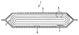
- FIG. 1 It is a cross-sectional schematic diagram of the flat type nonaqueous electrolyte battery of an embodiment. It is an expanded sectional view of the A section of FIG. It is the perspective view which extracted a part of negative electrode. It is the perspective view which extracted a part of positive electrode.
- FIG. 1 is a schematic cross-sectional view of a flat-type nonaqueous electrolyte battery 1.
- FIG. 2 is an enlarged cross-sectional view of a portion A in FIG.
- the nonaqueous electrolyte battery 1 includes a wound electrode group 2.
- the wound electrode group 2 is housed in the exterior member 3.
- the exterior member 3 is further filled with a nonaqueous electrolyte (not shown).
- the wound electrode group 2 includes a positive electrode 4, a negative electrode 5, and a separator 6, as shown in FIG.
- the wound electrode group 2 is formed by laminating the positive electrode 4 and the negative electrode 5 with the separator 6 interposed between them and winding them into a flat shape.
- a positive electrode terminal 7 is electrically connected to the positive electrode 4
- a negative electrode terminal 8 is electrically connected to the negative electrode 5.
- the exterior member 3 is a laminated film exterior bag.
- the electrode group 2 and the non-aqueous electrolyte are sealed by heat-sealing the opening of the laminated film exterior bag with the positive electrode terminal 7 and the negative electrode terminal 8 extended.
- the exterior member is not limited to a laminate film, and for example, a metal can can be used.
- the positive electrode 4 includes a positive electrode current collector 4a and a positive electrode active material layer 4b.
- the positive electrode active material layer 4b includes a positive electrode active material, and optionally a conductive agent and a binder.
- the positive electrode active material layer 4b is provided on one side or both sides of the positive electrode current collector 4a.
- a lithium transition metal composite oxide can be used as the positive electrode active material contained in the positive electrode active material layer 4b.
- a lithium transition metal composite oxide can be used. Examples include LiCoO 2 , Li 1 + a (Mn, Ni, Co) 1-a O 2 (0.0 ⁇ a ⁇ 0.2), Li 1 + b Ni 1-bc M1 c O 2 (0.0 ⁇ b ⁇ 0.2 , 0.0 ⁇ c ⁇ 0.4, M1 is at least one element selected from Co, Al and Fe), Li 1 + d Mn 2-de M2 e O 4 (0 ⁇ d ⁇ 0.3, 0 ⁇ e ⁇ 0.3 , M2 is Mg, Al, Fe, at least one element selected from Co and Ni), LiM3PO 4 (M3 is at least one element selected from Fe, Co and Ni) are included. These composite oxides may be used alone or in combination of two or more.
- the conductive agent is used to suppress the contact resistance between the active material and the current collector.
- Examples include carbonaceous materials such as acetylene black, carbon black and graphite.
- the binder is used to bind the active material and the conductive agent.
- examples thereof include polytetrafluoroethylene (PTFE), polyvinylidene fluoride (PVdF), and fluorine-based rubber.
- the mixing ratio of the positive electrode active material, the conductive agent, and the binder is 80% by mass to 95% by mass for the positive electrode active material, 3% by mass to 18% by mass for the conductive agent, and 2% by mass to 17% by mass for the binder. % Or less is preferable.
- the conductive agent is contained in an amount of 3% by mass or more, the above-described effects can be obtained.
- the binder is contained in an amount of 2% by mass or more, sufficient electrode strength can be obtained, and when it is contained in the range of 17% by mass or less, the amount of the insulator can be reduced and the internal resistance can be reduced.
- the positive electrode current collector 4a is preferably an aluminum foil or an aluminum alloy foil containing one or more elements selected from the group consisting of Mg, Ti, Zn, Mn, Fe, Cu and Si.
- the positive electrode is prepared by suspending a positive electrode active material, a conductive agent, and a binder in a commonly used solvent to prepare a slurry, applying the slurry to a positive electrode current collector, drying, and forming a positive electrode layer It can be produced by rolling.
- N-methylethylpyrrolidone can be used as the solvent.
- the ratio of the total mass of the positive electrode active material, the conductive agent and the binder to the mass of the solvent is preferably in the range of 50:50 to 80:20.
- the negative electrode 5 includes a negative electrode current collector 5a and a negative electrode active material layer 5b.
- the negative electrode active material layer 5b includes a negative electrode active material, and optionally a conductive agent and a binder.
- the negative electrode active material layer 5b is provided on one side or both sides of the negative electrode current collector 5a.
- FIG. 3 is a perspective view showing an example of the negative electrode.
- FIG. 3 shows a part of the negative electrode 5 in which the negative electrode active material layer 5b is provided on both surfaces of the negative electrode current collector 5a.
- a surface that is one surface of the negative electrode current collector 5a and faces the positive electrode 4 is referred to as a second surface.
- First negative electrode active material layer 5b 1 is provided on a portion of the second surface.
- Second negative electrode active material layer 5b 2 are provided on a portion of the back surface of the second surface of the negative electrode current collector 5a.
- Negative electrode current collector 5a is first anode active and a second coating portion 5c material layer 5b 1 is provided, and a second coating not the anode active material layer 5b 1 of the first are present Part 5c and a second non-coated part 5d adjacent to each other in a direction parallel to the second surface.
- the second non-coated portion 5d is adjacent to at least one edge of the negative electrode current collector 5a and extends along the at least one edge.
- the second non-coated portion 5d functions as a negative electrode tab.
- the negative electrode terminal 8 shown in FIG. 1 is connected to the second non-coated portion 5d directly or via a conductive member such as a lead. Thereby, the negative electrode 5 and the negative electrode terminal 8 are electrically connected.
- the length from the boundary between the second coating part 5c and the second non-coating part 5d to the edge where the second non-coating part 5d is adjacent is referred to as L2.
- This L2 is in the range of 5 mm to 20 mm.
- the connection area between the second non-coated portion 5d and the negative electrode terminal 8 or the conductive member can be increased, and the connection resistance can be reduced.
- the electrical resistance can be reduced.
- the fall of energy density can be prevented by making length L2 into 20 mm or less.
- the minimum value of the length from the boundary of the 2nd coating part 5c and the 2nd non-coating part 5d to the edge of a negative electrode collector is 5 mm or more, and the maximum value of this length is 20 mm or less It is.
- the density of the first negative electrode active material layer 5b1 is in the range of 2.1 g / cc or more and 2.4 g / cc or less.
- the density of the second negative electrode active material layer 5b 2 is also preferably within the above range.
- the density is a value calculated by measuring the thickness and area of the negative electrode active material layer, calculating the volume, and calculating the volume and mass. That is, the density referred to here is the volume when both the open holes communicating with the outside air in the negative electrode active material layer and the closed holes not communicating with the outside air are included in the volume. Density, so-called bulk density.
- the ratio W1 / W2 of the mass W1 per unit area of the second coated part 5c to the mass W2 per unit area of the second non-coated part 5d is 0.997 or more and 1 or less.
- the mass ratio W1 / W2 is calculated from the result of measuring the mass per unit area (for example, g / cm 2 ) for each of the second coated part 5c and the second non-coated part 5d.
- the mass ratio (W1 / W2) within the above range, the difference in mass per unit area between the second coated portion 5c and the second non-coated portion 5d can be reduced. For this reason, it is possible to reduce the distortion of the electrode.
- the distortion of the electrodes is small, a gap is hardly generated between the electrodes when the electrodes are wound or stacked. As a result, it is possible to reduce the electrical resistance inside the battery. Thereby, a negative electrode with small internal resistance can be provided.
- the second negative electrode active material layer 5b 2 is preferably provided only in the second coating part. That is, the first negative electrode active material layer 5b 1 second and the negative electrode active material layer 5b 2 is preferably provided at a position facing each other across the anode current collector 5a.
- a titanium-containing metal composite oxide can be used as the negative electrode active material contained in the negative electrode active material layer 5b.
- examples thereof include a lithium titanium oxide and a titanium-based oxide that does not contain lithium during synthesis but can contain lithium by charge and discharge.
- lithium titanium oxide examples include Li 4 + x Ti 5 O 12 (0 ⁇ x ⁇ 3) having a spinel structure and Li 2 + y Ti 3 O 7 (0 ⁇ y ⁇ 3) having a ramsteride structure. included.
- titanium-based oxides include TiO 2 and metal composite oxides containing Ti and at least one element selected from the group consisting of P, V, Sn, Cu, Ni, Co, and Fe. .
- TiO 2 has an anatase structure, and preferably has a low crystallinity and a heat treatment temperature of 300 to 500 ° C.
- metal composite oxides include TiO 2 -P 2 O 5 , TiO 2 -V 2 O 5 , TiO 2 -P 2 O 5 -SnO 2 , and TiO 2 -P 2 O 5 -MeO (Me At least one element selected from the group consisting of Cu, Ni, Co and Fe).
- the metal composite oxide is preferably one in which a crystal phase and an amorphous phase coexist, or one having a microstructure in which an amorphous phase exists alone.
- the metal composite oxide having such a microstructure can greatly improve the cycle performance.
- the negative electrode active material is selected from lithium titanium oxide and a metal composite oxide containing Ti and at least one element selected from the group consisting of P, V, Sn, Cu, Ni, Co, and Fe. Is more preferable.
- the conductive agent is used to suppress the contact resistance between the active material and the current collector.
- Examples include carbonaceous materials such as acetylene black, carbon black and graphite.
- the binder is used to bind the active material and the conductive agent.
- examples thereof include polytetrafluoroethylene (PTFE), polyvinylidene fluoride (PVdF), fluorine-based rubber, and styrene butadiene rubber.
- the compounding ratio of the negative electrode active material, the conductive agent and the binder is such that the negative electrode active material is 70% by mass to 96% by mass, the conductive agent is 2% by mass to 28% by mass, and the binder is 2% by mass to 28% by mass. % Or less is preferable.
- the conductive agent By containing 2% by mass or more of the conductive agent, the current collecting performance of the negative electrode layer can be improved, and the large current characteristics of the battery can be improved.
- the binder is contained in an amount of 2% by mass or more, the binding property between the negative electrode layer and the negative electrode current collector can be improved, and the cycle characteristics can be improved.
- the conductive agent and the binder are each preferably contained in a range of 28% by mass or less.
- the negative electrode current collector 5a is preferably an aluminum foil, an aluminum alloy foil containing one or more elements selected from the group consisting of Mg, Ti, Zn, Mn, Fe, Cu and Si, or a copper foil.
- An aluminum foil or an aluminum alloy foil as described above is more preferable because it is electrochemically stable in a potential range nobler than 1.0 V.
- a negative electrode active material a negative electrode active material, a conductive agent, and a binder are suspended in a solvent to prepare a slurry.
- a solvent for example, N-methylethylpyrrolidone can be used as the solvent.
- the mixing ratio of the total mass of the negative electrode active material, the conductive agent and the binder to the mass of the solvent is preferably in the range of 50:50 to 80:20.
- the slurry is applied to one or both sides of the negative electrode current collector and dried to form a negative electrode active material layer.
- the slurry is applied to the negative electrode current collector, leaving a non-coated part continuous with a certain width.
- the second non-coated portion is preferably adjacent to the edge along the longitudinal direction of the negative electrode current collector. Or two 2nd non-coating parts may be provided and each may adjoin both the edges along the longitudinal direction of a negative electrode collector.
- the length of the second non-coated part is adjusted within the range of 5 mm or more and 20 mm or less.
- the length of the second non-coated portion refers to the edge of the negative electrode current collector adjacent to the second non-coated portion from the boundary between the second coated portion and the second non-coated portion. Is the length. In the case of the negative electrode used for the wound electrode group, this length refers to the length in the direction orthogonal to the longitudinal direction.
- the negative electrode current collector on which the negative electrode active material layer is formed is rolled so that the density of the negative electrode active material layer is in the range of 2.1 g / cc or more and 2.4 g / cc or less. Rolling can be performed using a roller press.
- the negative electrode current collector is also rolled together with the negative electrode active material layer.
- the roller since the diameter of the roller is constant, the roller does not contact the second non-coated portion where the active material layer is not coated. Therefore, the second coated portion coated with the active material layer is rolled to reduce the mass W1 per unit area, while the second non-coated portion is not rolled and the mass W2 per unit area is reduced. It does not change.
- the mass W1 per unit area of the second coated part is smaller than the mass W2 per unit area of the second non-coated part. That is, the mass ratio (W1 / W2) is less than 1.0, for example, about 0.995. This mass ratio (W1 / W2) is difficult to be set to 0.997 or more even when, for example, rolling is performed using a roller having a diameter exceeding 400 mm.
- the mass ratio (W1 / W2) can be set to 0.997 or more by extending the second non-coated portion to reduce the mass per unit area (W2).
- the stretching of the second non-coated portion can be realized by subjecting the entire negative electrode to a tensile treatment. In the tensile treatment, tension is applied to the entire negative electrode in a direction parallel to the boundary between the second coated part and the second non-coated part. By this tensile treatment, it is possible to selectively stretch the non-coated portion.
- the second non-coated portion is selectively stretched because the second coated portion is rolled while the second non-coated portion is not rolled, so that it is uniform throughout the negative electrode. It is considered that this is because the tension is concentrated on the second non-coated portion even when tension is applied.
- an aluminum foil generally used as a current collector is stretched when a tension corresponding to approximately 100 N / mm 2 is applied in a direction perpendicular to the cross section. Therefore, in order to stretch an aluminum foil having a thickness of 15 ⁇ m, a tension of about 1500 N / m is required.
- the second non-coated portion can be stretched even with a tension of about 300 N / m. This also shows that the second non-coated portion is selectively stretched even when a uniform tension is applied to the entire negative electrode.
- the non-coated portion can be stretched with a tension of about 300 N / m, so that the electrode can be prevented from breaking.
- the tensile treatment can be performed using, for example, a rewinding device including a winding device and a winding device.
- a rewinding device including a winding device and a winding device.
- the tension T applied to the electrode can be controlled.
- the electrode after the rolling process is passed through a rewinding device, and the tensioning process is performed by rolling and winding the electrode while controlling the tension T.
- the tension T is preferably in the range of 100 N / m to 600 N / m. By giving a tension in this range, the first non-coated portion can be stretched without breaking the electrode, and the mass ratio (W1 / W2) can be 0.997 or more.
- the heating temperature is preferably 60 ° C. or higher and 140 ° C. or lower. The above effects can be obtained by heating to 60 ° C. or higher. Further, by heating at 140 ° C. or lower, it is possible to prevent the binder contained in the active material layer from being deteriorated at a high temperature and deteriorating battery performance.
- the heating temperature is more preferably 100 ° C. or higher and 140 ° C. or lower. It can heat using warm air, an infrared heater, or an electromagnetic induction heater. Alternatively, it can be overheated by bringing the electrode into contact with a heated roller.
- the tension T is preferably in the range of 50 N / m to 400 N / m.
- Nonaqueous electrolyte a liquid non-aqueous electrolyte or a gel-like non-aqueous electrolyte can be used.
- the liquid non-aqueous electrolyte can be prepared by dissolving the electrolyte in an organic solvent.
- the gel-like nonaqueous electrolyte can be prepared by combining a liquid electrolyte and a polymer material.
- the concentration of the electrolyte in the liquid non-aqueous electrolyte is preferably in the range of 0.5 mol / L to 2.5 mol / L.
- electrolytes examples include lithium perchlorate (LiClO 4 ), lithium hexafluorophosphate (LiPF 6 ), lithium tetrafluoroborate (LiBF 4 ), lithium arsenic hexafluoride (LiAsF 6 ), trifluorometa Lithium salts such as lithium sulfonate (LiCF 3 SO 3 ) and lithium bistrifluoromethylsulfonylimide [LiN (CF 3 SO 2 ) 2 ] and mixtures thereof are included.
- the electrolyte is preferably one that is not easily oxidized even at a high potential, and LiPF 6 is most preferred.
- organic solvents examples include propylene carbonate (PC), ethylene carbonate (EC), cyclic carbonates such as vinylene carbonate; Carbonates; tetrahydrofuran (THF), cyclic ethers such as 2methyltetrahydrofuran (2MeTHF), dioxolane (DOX); chain ethers such as dimethoxyethane (DME) and diethoxyethane (DEE); ⁇ -butyrolactone (GBL), Acetonitrile (AN) and sulfolane (SL) are included.
- PC propylene carbonate
- EC ethylene carbonate
- cyclic carbonates such as vinylene carbonate
- Carbonates tetrahydrofuran (THF)
- cyclic ethers such as 2methyltetrahydrofuran (2MeTHF)
- DOX dioxolane
- chain ethers such as dimethoxyethane (DME) and diethoxyethane (DEE)
- polymer material examples include polyvinylidene fluoride (PVdF), polyacrylonitrile (PAN), and polyethylene oxide (PEO).
- PVdF polyvinylidene fluoride
- PAN polyacrylonitrile
- PEO polyethylene oxide
- the non-aqueous electrolyte may be a room temperature molten salt (ionic melt) containing lithium ions, a polymer solid electrolyte, an inorganic solid electrolyte, or the like.
- the room temperature molten salt refers to a compound that can exist as a liquid at room temperature (15 to 25 ° C.) among organic salts composed of a combination of an organic cation and an anion.
- the room temperature molten salt includes a room temperature molten salt that exists alone as a liquid, a room temperature molten salt that becomes liquid when mixed with an electrolyte, and a room temperature molten salt that becomes liquid when dissolved in an organic solvent.
- the melting point of a room temperature molten salt used for a nonaqueous electrolyte battery is 25 ° C. or less.
- the organic cation generally has a quaternary ammonium skeleton.
- the polymer solid electrolyte is prepared by dissolving an electrolyte in a polymer material and solidifying it.
- the inorganic solid electrolyte is a solid material having lithium ion conductivity.
- a porous film formed from a material such as polyethylene, polypropylene, cellulose, and polyvinylidene fluoride (PVdF), a synthetic resin nonwoven fabric, and the like can be used.
- PVdF polyvinylidene fluoride
- a porous film made of polyethylene or polypropylene can be melted at a constant temperature to cut off the current. Therefore, those porous films are preferable from the viewpoint of improving safety.
- the porous film formed from cellulose can contain more electrolyte with the same thickness as the separator formed from other materials, the lithium ion conductivity in the electrolyte is relatively large. It is preferably used in a high-power non-aqueous electrolyte battery that requires a large current to flow.
- a bag-like container made of a laminated film or a metal container can be used as the exterior member.
- the thickness of the laminate film is preferably 0.5 mm or less, and more preferably 0.2 mm or less.
- the thickness of the metal container is preferably 1 mm or less, more preferably 0.5 mm or less, and further preferably 0.3 mm or less.
- the shape of the exterior member may be a flat type (thin type), a square type, a cylindrical type, a coin type, a button type, or the like.
- the exterior member may be, for example, a small battery exterior member that is loaded on a portable electronic device or the like, or a large battery exterior member that is loaded on a two-wheel to four-wheel automobile or the like, depending on the battery size.
- the laminate film a multilayer film in which a metal layer is interposed between resin layers is used.
- the metal layer is preferably an aluminum foil or an aluminum alloy foil for weight reduction.
- the resin layer is used to reinforce the metal layer.
- resins include polymeric materials such as polypropylene (PP), polyethylene (PE), nylon and polyethylene terephthalate (PET).
- PP polypropylene
- PE polyethylene
- PET polyethylene terephthalate
- the laminate film can be formed into the shape of an exterior member by sealing by heat sealing.
- Metal containers are made from aluminum or aluminum alloy.
- the aluminum alloy is preferably an alloy containing elements such as magnesium, zinc, and silicon.
- the alloy contains a transition metal such as iron, copper, nickel, or chromium, the content is preferably 1% by mass or less.
- a non-aqueous electrolyte secondary battery using a wound electrode group has been described as an example.
- the present invention is not limited to this, and a stacked electrode group may be used instead of the wound electrode group.
- the nonaqueous electrolyte battery of the second embodiment has the same configuration as that of the first embodiment except that a positive electrode described below is used.
- the positive electrode 4 includes a positive electrode current collector 4a and a positive electrode active material layer 4b.
- the positive electrode active material layer 4b includes a positive electrode active material, and optionally a conductive agent and a binder.
- the positive electrode active material layer 4b is provided on one side or both sides of the positive electrode current collector 4a.
- the positive electrode active material, the conductive agent and the binder, the blending ratio thereof, and the positive electrode current collector are the same as those described in the first embodiment.
- FIG. 4 is a perspective view showing an example of the positive electrode.
- FIG. 4 shows a part of the positive electrode 4 in which the positive electrode active material layer 4b is provided on both surfaces of the positive electrode current collector 4a.
- One surface of the positive electrode current collector 4a and the surface facing the negative electrode 5 is referred to as a first surface.
- a first positive electrode active material layer 4b 1 is provided on a part of the first surface.
- Second positive electrode active material layer 4b 2 is provided on a portion of the back surface of the first surface of the positive electrode current collector 4a.
- Cathode current collector 4a, the first and the coated portion 4c, the first positive electrode active material layer 4b 1 does not exist and the first coating of the first positive electrode active material layer 4b 1 provided Part 4c and first non-coated part 4d adjacent to each other in the direction parallel to the first surface.
- the first non-coated portion 4d is adjacent to at least one edge of the positive electrode current collector 4a and extends along the at least one edge.
- the first non-coated part 4d functions as a positive electrode tab.
- the positive terminal 7 shown in FIG. 1 is connected to the first non-coated portion 4d directly or via a conductive member such as a lead. Thereby, the positive electrode 4 and the positive electrode terminal 7 are electrically connected.
- the length from the boundary between the first coating part 4c and the first non-coating part 4d to the edge where the first non-coating part 4d is adjacent is referred to as L1.
- This L1 is in the range of 5 mm to 20 mm.
- the minimum value of the length from the boundary of the 1st coating part 4c and the 1st non-coating part 4d to the edge of a positive electrode electrical power collector is 5 mm or more, and the maximum value of this length is 20 mm or less It is.
- the density of the first positive electrode active material layer 4b1 is in the range of 3.1 g / cc to 3.4 g / cc.
- the density is a value calculated from the volume and mass obtained by measuring the thickness and area of the positive electrode active material layer and calculating the volume. That is, the density referred to here is the value obtained when the volume of both the open holes communicating with the outside air in the positive electrode active material layer and the isolated closed holes not communicating with the outside air are included in the volume. Density, so-called bulk density.
- the ratio W1 / W2 of the mass W1 per unit area of the first coating part 4c to the mass W2 per unit area of the first non-coating part 4d is 0.997 or more and 1 or less.
- the mass ratio W1 / W2 is calculated from the result of measuring the mass per unit area (for example, g / cm 2 ) for each of the first coated part 4c and the first non-coated part 4d.
- the second positive electrode active material layer 4b 2 is preferably provided only in the first coating part. That is, the first positive electrode active material layer 4b 1 and the second positive electrode active material layer 4b 2, is preferably provided in a position facing each other across the positive electrode current collector 4a.
- the mass ratio (W1 / W2) within the above range, the difference in mass per unit area between the first coated portion 4c and the first non-coated portion 4d can be reduced. For this reason, it is possible to reduce the distortion of the electrode.
- the distortion of the electrodes is small, a gap is hardly generated between the electrodes when the electrodes are wound or stacked. As a result, it is possible to reduce the electrical resistance inside the battery. Thereby, a positive electrode with small internal resistance can be provided.
- the large current characteristics of the nonaqueous electrolyte battery can be further improved.
- a positive electrode active material, a conductive agent, and a binder are suspended in a solvent to prepare a slurry.
- a solvent for example, N-methylethylpyrrolidone can be used as the solvent.
- the mixing ratio of the total mass of the positive electrode active material, the conductive agent and the binder to the mass of the solvent is preferably in the range of 50:50 to 80:20.
- the slurry is applied to one or both sides of the positive electrode current collector and dried to form a positive electrode active material layer.
- the slurry is applied to the positive electrode current collector, leaving the first non-coated portion continuous with a constant width.
- the first non-coated portion is preferably adjacent to the edge along the longitudinal direction of the positive electrode current collector.
- two 1st non-coating parts may be provided and may each adjoin to both the edges along the longitudinal direction of a positive electrode electrical power collector.
- the length of the 1st non-coating part is adjusted in the range of 5 mm or more and 20 mm or less.
- the length of the first non-coated portion refers to the edge of the positive electrode current collector adjacent to the first non-coated portion from the boundary between the first coated portion and the first non-coated portion. Is the length. In the case of the positive electrode used for the wound electrode group, this length refers to the length in the direction orthogonal to the longitudinal direction.
- the positive electrode current collector on which the positive electrode active material layer is formed is rolled so that the density of the positive electrode active material layer is in the range of 3.1 g / cc to 3.4 g / cc. Rolling can be performed using a roller press.
- the positive electrode current collector is also rolled together with the positive electrode active material layer.
- the roller since the diameter of the roller is constant, the roller does not contact the non-coated portion where the active material layer is not coated. Therefore, the coated portion coated with the active material layer is rolled to reduce the mass W1 per unit area, while the first non-coated portion is not rolled and the mass W2 per unit area does not change.
- the mass W1 per unit area of the first coated part is smaller than the mass W2 per unit area of the first non-coated part. That is, the mass ratio (W1 / W2) is less than 1.0, for example, about 0.995. This mass ratio (W1 / W2) is difficult to be set to 0.997 or more even when, for example, rolling is performed using a roller having a diameter exceeding 400 mm.
- the mass ratio (W1 / W2) can be set to 0.997 or more by extending the first non-coated portion to reduce the mass per unit area (W2).
- the stretching of the first non-coated portion can be realized by subjecting the entire positive electrode to a tensile treatment. In the tension treatment, tension is applied to the whole positive electrode in a direction parallel to the boundary between the first coated part and the first non-coated part. By this tensile treatment, the first non-coated portion can be selectively stretched.
- the tensile treatment can be performed in the same manner as the tensile treatment in the negative electrode manufacturing method of the first embodiment.
- the electrode group is composed of the positive electrode 4, the negative electrode 5, and the separator 6 as described above.
- the separator includes first and second portions spaced apart from each other and a third portion interposed between the first and second portions.
- the third part of the separator is interposed between the first coating part of the positive electrode and the second coating part of the negative electrode.
- the first non-coated portion of the positive electrode is preferably positioned so as to face the first portion of the separator
- the second non-coated portion of the negative electrode is preferably positioned so as to face the second portion of the separator.
- the first non-coated portion of the positive electrode is preferably located on the opposite side in the winding axis direction to the second non-coated portion of the negative electrode.
- LiCoO 2 was used as the positive electrode active material
- acetylene black and carbon black were used as the conductive agent
- polyvinylidene fluoride was used as the binder.
- Each was mixed at a mass ratio of 85: 5: 5: 5 and dispersed in an organic solvent to prepare a slurry.
- This slurry was applied to an aluminum foil having a thickness of 20 ⁇ m and dried to form an active material layer.
- the slurry was applied to the back side of the aluminum foil and dried to form an active material layer.
- the active material layers on both sides of the aluminum foil were formed so that their longitudinal sides coincided. Specifically, it formed so that the shift
- the aluminum foil having an active material layer on both sides obtained above was cut with a certain width to obtain a positive electrode before rolling in which a non-coated part with a width of 15 mm was present at one end in the longitudinal direction.
- the positive electrode before rolling was rolled using a roll press to obtain a positive electrode. In the rolling, the roll press load was adjusted so that the density of the active material layer was 3.2 g / cc.
- Li 4 Ti 5 O 12 was used as the negative electrode active material, carbon black was used as the conductive agent, and polyvinylidene fluoride was used as the binder.
- Each was mixed at a mass ratio of 85: 10: 5 and dispersed in an organic solvent to prepare a slurry.
- This slurry was applied to an aluminum foil having a thickness of 20 ⁇ m and dried to form an active material layer.
- the slurry was applied to the back side of the aluminum foil and dried to form an active material layer.
- the active material layers on both sides of the aluminum foil were formed so that their longitudinal sides coincided. Specifically, it formed so that the shift
- the aluminum foil having the active material layer on both sides obtained above was cut with a certain width to obtain a negative electrode before rolling in which a non-coated part with a width of 15 mm was present at one end in the longitudinal direction.
- the negative electrode before rolling was rolled using a roll press to obtain a negative electrode. In rolling, the load of the roll press was adjusted so that the density of the active material layer was 2.2 g / cc.
- ⁇ Preparation of nonaqueous electrolyte secondary battery> The positive electrode and the negative electrode manufactured as described above were laminated with a separator in between, and wound into a coil to obtain an electrode group.
- the non-coated portion of the positive electrode protruded from one end of the electrode group, and the non-coated portion of the negative electrode protruded from the other end of the electrode group.
- the non-coated portion of the positive electrode was bundled and the positive electrode terminal was ultrasonically bonded.
- the non-coated part of the negative electrode was bundled, and the negative electrode terminal was ultrasonically bonded.
- Aluminum plates were used for the positive and negative terminals.
- This electrode group was put in an aluminum laminate exterior member, and a nonaqueous electrolyte was injected and sealed to obtain a nonaqueous electrolyte secondary battery.
- the coating part was cut out from the positive electrode manufactured similarly to the positive electrode used for preparation of said nonaqueous electrolyte secondary battery.
- the active material layer on the surface of the coated part was removed with an organic solvent.
- the mass and area of the remaining aluminum foil were measured, and the mass W1 per unit area was calculated.
- the non-coating part was cut out, the mass and area were measured, and mass W2 per unit area was computed.
- the mass ratio (W1 / W2) of the positive electrode was 0.995.
- the coated part was cut out from the negative electrode produced in the same manner as the negative electrode used for the production of the nonaqueous electrolyte secondary battery.
- the active material layer on the surface of the coated part was removed with an organic solvent.
- the mass and area of the remaining aluminum foil were measured, and the mass W1 per unit area was calculated.
- the non-coating part was cut out, the mass and area were measured, and mass W2 per unit area was computed.
- the mass ratio (W1 / W2) of the negative electrode was 0.995.
- ⁇ Discharge test> A discharge test was performed using the non-aqueous electrolyte secondary battery produced as described above. The battery was charged to half the capacity. Thereafter, the battery was discharged at a current of 20 C, the product of the voltage 10 seconds after the start of discharge and the discharge current was taken, and the output was calculated.
- Example 1 After producing a positive electrode in the same manner as in Comparative Example 1, a tensile treatment was performed. The tensile treatment was performed by passing the positive electrode through an electrode rewinding device equipped with a rolling-out device and a winding device, and changing the tension by setting the tension to 500 N / m. The negative electrode and the nonaqueous electrolyte secondary battery were produced in the same manner as in Comparative Example 1. Measurements and discharge tests were performed using this battery. Table 1 shows the density and mass ratio (W1 / W2) of the active material layers of the positive electrode and the negative electrode, and the length of the non-coated part.
- Example 2 After producing the negative electrode in the same manner as in Comparative Example 1, a tensile treatment was performed. The tensile treatment was performed by passing the negative electrode through an electrode rewinding device equipped with a rolling-out device and a winding device, and changing the tension while setting the tension to 500 N / m. The positive electrode and the nonaqueous electrolyte secondary battery were produced in the same manner as in Comparative Example 1. Measurements and discharge tests were performed using this battery. Table 1 shows the density and mass ratio (W1 / W2) of the active material layers of the positive electrode and the negative electrode, and the length of the non-coated part.
- Example 3 A nonaqueous electrolyte secondary battery was produced in the same manner as in Comparative Example 1 except that the positive electrode produced in the same manner as in Example 1 and the negative electrode produced in the same manner as in Example 2 were used. Measurements and discharge tests were performed using this battery. Table 1 shows the density and mass ratio (W1 / W2) of the active material layers of the positive electrode and the negative electrode, and the length of the non-coated part.
- Comparative Example 2 A nonaqueous electrolyte secondary battery was produced in the same manner as in Comparative Example 1 except that the lengths of the non-coated portions of the positive electrode and the negative electrode were each 10 mm. Measurements and discharge tests were performed using this battery. Table 1 shows the density and mass ratio (W1 / W2) of the active material layers of the positive electrode and the negative electrode, and the length of the non-coated part.
- Example 4 A nonaqueous electrolyte secondary battery was produced in the same manner as in Comparative Example 1 except that the positive electrode of Comparative Example 2 was subjected to a tensile treatment. Measurements and discharge tests were performed using this battery. Table 1 shows the density and mass ratio (W1 / W2) of the active material layers of the positive electrode and the negative electrode, and the length of the non-coated part. Tensile treatment was performed as described in Example 1.
- Example 5 A nonaqueous electrolyte secondary battery was produced in the same manner as in Comparative Example 1 except that the negative electrode of Comparative Example 2 was subjected to a tensile treatment. Measurements and discharge tests were performed using this battery. Table 1 shows the density and mass ratio (W1 / W2) of the active material layers of the positive electrode and the negative electrode, and the length of the non-coated part. Tensile treatment was performed as described in Example 1.
- Example 6 A nonaqueous electrolyte secondary battery was produced in the same manner as in Comparative Example 1 except that each of the positive electrode and the negative electrode in Comparative Example 2 was subjected to a tensile treatment. Measurements and discharge tests were performed using this battery. Table 1 shows the density and mass ratio (W1 / W2) of the active material layers of the positive electrode and the negative electrode, and the length of the non-coated part. Tensile treatment was performed as described in Example 1.
- Comparative Example 3 A nonaqueous electrolyte secondary battery was produced in the same manner as in Comparative Example 1 except that the lengths of the non-coated portions of the positive electrode and the negative electrode were each 5 mm. Measurements and discharge tests were performed using this battery. Table 1 shows the density and mass ratio (W1 / W2) of the active material layers of the positive electrode and the negative electrode, and the length of the non-coated part.
- Example 7 A nonaqueous electrolyte secondary battery was produced in the same manner as in Comparative Example 1 except that the positive electrode of Comparative Example 3 was subjected to a tensile treatment. Measurements and discharge tests were performed using this battery. Table 1 shows the density and mass ratio (W1 / W2) of the active material layers of the positive electrode and the negative electrode, and the length of the non-coated part. Tensile treatment was performed as described in Example 1.
- Example 8 A nonaqueous electrolyte secondary battery was produced in the same manner as in Comparative Example 1 except that the negative electrode of Comparative Example 3 was subjected to a tensile treatment. Measurements and discharge tests were performed using this battery. Table 1 shows the density and mass ratio (W1 / W2) of the active material layers of the positive electrode and the negative electrode, and the length of the non-coated part. Tensile treatment was performed as described in Example 1.
- Example 9 A nonaqueous electrolyte secondary battery was produced in the same manner as in Comparative Example 1 except that each of the positive electrode and the negative electrode in Comparative Example 3 was subjected to a tensile treatment. Measurements and discharge tests were performed using this battery. Table 1 shows the density and mass ratio (W1 / W2) of the active material layers of the positive electrode and the negative electrode, and the length of the non-coated part. Tensile treatment was performed as described in Example 1.
- Comparative Example 4 A nonaqueous electrolyte secondary battery was produced in the same manner as in Comparative Example 1 except that the lengths of the non-coated portions of the positive electrode and the negative electrode were each 2 mm. Measurements and discharge tests were performed using this battery. Table 1 shows the density and mass ratio (W1 / W2) of the active material layers of the positive electrode and the negative electrode, and the length of the non-coated part.
- Comparative Example 5 A nonaqueous electrolyte secondary battery was produced in the same manner as in Comparative Example 1 except that the positive electrode of Comparative Example 4 was subjected to a tensile treatment. Measurements and discharge tests were performed using this battery. Table 1 shows the density and mass ratio (W1 / W2) of the active material layers of the positive electrode and the negative electrode, and the length of the non-coated part. Tensile treatment was performed as described in Example 1.
- Comparative Example 6 A nonaqueous electrolyte secondary battery was produced in the same manner as in Comparative Example 1 except that the negative electrode of Comparative Example 4 was subjected to a tensile treatment. Measurements and discharge tests were performed using this battery. Table 1 shows the density and mass ratio (W1 / W2) of the active material layers of the positive electrode and the negative electrode, and the length of the non-coated part. Tensile treatment was performed as described in Example 1.
- Comparative Example 7 A nonaqueous electrolyte secondary battery was produced in the same manner as in Comparative Example 1 except that each of the positive electrode and the negative electrode in Comparative Example 4 was subjected to a tensile treatment. Measurements and discharge tests were performed using this battery. Table 1 shows the density and mass ratio (W1 / W2) of the active material layers of the positive electrode and the negative electrode, and the length of the non-coated part. Tensile treatment was performed as described in Example 1.
- Comparative Example 8 A nonaqueous electrolyte secondary battery was produced in the same manner as in Comparative Example 1 except that the density of the active material layers of the positive electrode and the negative electrode was changed by changing the load of the roll press. Measurements and discharge tests were performed using this battery. Table 1 shows the density and mass ratio (W1 / W2) of the active material layers of the positive electrode and the negative electrode, and the length of the non-coated part.
- Example 10 A nonaqueous electrolyte secondary battery was produced in the same manner as in Comparative Example 1 except that the positive electrode of Comparative Example 8 was subjected to a tensile treatment. Measurements and discharge tests were performed using this battery. Table 1 shows the density and mass ratio (W1 / W2) of the active material layers of the positive electrode and the negative electrode, and the length of the non-coated part. Tensile treatment was performed as described in Example 1.
- Example 11 A nonaqueous electrolyte secondary battery was produced in the same manner as in Comparative Example 1 except that the negative electrode of Comparative Example 8 was subjected to a tensile treatment. Measurements and discharge tests were performed using this battery. Table 1 shows the density and mass ratio (W1 / W2) of the active material layers of the positive electrode and the negative electrode, and the length of the non-coated part. Tensile treatment was performed as described in Example 1.
- Example 12 A nonaqueous electrolyte secondary battery was produced in the same manner as in Comparative Example 1 except that each of the positive electrode and the negative electrode in Comparative Example 8 was subjected to a tensile treatment. Measurements and discharge tests were performed using this battery. Table 1 shows the density and mass ratio (W1 / W2) of the active material layers of the positive electrode and the negative electrode, and the length of the non-coated part. Tensile treatment was performed as described in Example 1.
- Comparative Example 9 A nonaqueous electrolyte secondary battery was produced in the same manner as in Comparative Example 1 except that the density of the active material layers of the positive electrode and the negative electrode was changed by changing the load of the roll press. Measurements and discharge tests were performed using this battery. Table 1 shows the density and mass ratio (W1 / W2) of the active material layers of the positive electrode and the negative electrode, and the length of the non-coated part.
- Comparative Example 10 A nonaqueous electrolyte secondary battery was produced in the same manner as in Comparative Example 1 except that the positive electrode of Comparative Example 9 was subjected to a tensile treatment. Measurements and discharge tests were performed using this battery. Table 1 shows the density and mass ratio (W1 / W2) of the active material layers of the positive electrode and the negative electrode, and the length of the non-coated part. Tensile treatment was performed as described in Example 1.
- Comparative Example 11 A nonaqueous electrolyte secondary battery was produced in the same manner as in Comparative Example 1 except that the negative electrode of Comparative Example 9 was subjected to a tensile treatment. Measurements and discharge tests were performed using this battery. Table 1 shows the density and mass ratio (W1 / W2) of the active material layers of the positive electrode and the negative electrode, and the length of the non-coated part. Tensile treatment was performed as described in Example 1.
- Comparative Example 12 A nonaqueous electrolyte secondary battery was produced in the same manner as in Comparative Example 1 except that each of the positive electrode and the negative electrode in Comparative Example 9 was subjected to a tensile treatment. Measurements and discharge tests were performed using this battery. Table 1 shows the density and mass ratio (W1 / W2) of the active material layers of the positive electrode and the negative electrode, and the length of the non-coated part. Tensile treatment was performed as described in Example 1.
- Comparative Example 13 A nonaqueous electrolyte secondary battery was produced in the same manner as in Comparative Example 1 except that the density of the active material layers of the positive electrode and the negative electrode was changed by changing the load of the roll press. Measurements and discharge tests were performed using this battery. Table 1 shows the density and mass ratio (W1 / W2) of the active material layers of the positive electrode and the negative electrode, and the length of the non-coated part.
- Example 13 A nonaqueous electrolyte secondary battery was produced in the same manner as in Comparative Example 1 except that the positive electrode of Comparative Example 13 was subjected to a tensile treatment. Measurements and discharge tests were performed using this battery. Table 1 shows the density and mass ratio (W1 / W2) of the active material layers of the positive electrode and the negative electrode, and the length of the non-coated part. Tensile treatment was performed as described in Example 1.
- Example 14 A nonaqueous electrolyte secondary battery was produced in the same manner as in Comparative Example 1 except that the negative electrode of Comparative Example 13 was subjected to a tensile treatment. Measurements and discharge tests were performed using this battery. Table 1 shows the density and mass ratio (W1 / W2) of the active material layers of the positive electrode and the negative electrode, and the length of the non-coated part. Tensile treatment was performed as described in Example 1.
- Example 15 A nonaqueous electrolyte secondary battery was produced in the same manner as in Comparative Example 1 except that each of the positive electrode and the negative electrode in Comparative Example 13 was subjected to a tensile treatment. Measurements and discharge tests were performed using this battery. Table 1 shows the density and mass ratio (W1 / W2) of the active material layers of the positive electrode and the negative electrode, and the length of the non-coated part. Tensile treatment was performed as described in Example 1.
- Comparative Example 14 A nonaqueous electrolyte secondary battery was produced in the same manner as in Comparative Example 1 except that the density of the active material layers of the positive electrode and the negative electrode was changed by changing the load of the roll press. Measurements and discharge tests were performed using this battery. Table 1 shows the density and mass ratio (W1 / W2) of the active material layers of the positive electrode and the negative electrode, and the length of the non-coated part.
- Comparative Example 15 A nonaqueous electrolyte secondary battery was produced in the same manner as in Comparative Example 1 except that LiNi 0.8 Co 0.17 Al 0.03 O 2 was used as the positive electrode active material. Measurements and discharge tests were performed using this battery. Table 1 shows the density and mass ratio (W1 / W2) of the active material layers of the positive electrode and the negative electrode, and the length of the non-coated part.
- Example 16 A nonaqueous electrolyte secondary battery was produced in the same manner as in Comparative Example 1 except that the positive electrode of Comparative Example 15 was subjected to a tensile treatment. Measurements and discharge tests were performed using this battery. Table 1 shows the density and mass ratio (W1 / W2) of the active material layers of the positive electrode and the negative electrode, and the length of the non-coated part. Tensile treatment was performed as described in Example 1.
- Example 17 A nonaqueous electrolyte secondary battery was produced in the same manner as in Comparative Example 1 except that the negative electrode of Comparative Example 15 was subjected to a tensile treatment. Measurements and discharge tests were performed using this battery. Table 1 shows the density and mass ratio (W1 / W2) of the active material layers of the positive electrode and the negative electrode, and the length of the non-coated part. Tensile treatment was performed as described in Example 1.
- Example 18 A nonaqueous electrolyte secondary battery was produced in the same manner as in Comparative Example 1 except that each of the positive electrode and the negative electrode in Comparative Example 15 was subjected to a tensile treatment. Measurements and discharge tests were performed using this battery. Table 1 shows the density and mass ratio (W1 / W2) of the active material layers of the positive electrode and the negative electrode, and the length of the non-coated part. Tensile treatment was performed as described in Example 1.
- Comparative Example 16 A nonaqueous electrolyte secondary battery was produced in the same manner as in Comparative Example 1 except that Li 1.1 Mn 1.8 Al 0.1 O 4 was used as the positive electrode active material. Measurements and discharge tests were performed using this battery. Table 1 shows the density and mass ratio (W1 / W2) of the active material layers of the positive electrode and the negative electrode, and the length of the non-coated part.
- Example 19 A nonaqueous electrolyte secondary battery was produced in the same manner as in Comparative Example 1 except that the positive electrode of Comparative Example 16 was subjected to a tensile treatment. Measurements and discharge tests were performed using this battery. Table 1 shows the density and mass ratio (W1 / W2) of the active material layers of the positive electrode and the negative electrode, and the length of the non-coated part. Tensile treatment was performed as described in Example 1.
- Example 20 A nonaqueous electrolyte secondary battery was produced in the same manner as in Comparative Example 1 except that the negative electrode of Comparative Example 16 was subjected to a tensile treatment. Measurements and discharge tests were performed using this battery. Table 1 shows the density and mass ratio (W1 / W2) of the active material layers of the positive electrode and the negative electrode, and the length of the non-coated part. Tensile treatment was performed as described in Example 1.
- Example 21 A nonaqueous electrolyte secondary battery was produced in the same manner as in Comparative Example 1 except that each of the positive electrode and the negative electrode in Comparative Example 16 was subjected to a tensile treatment. Measurements and discharge tests were performed using this battery. Table 1 shows the density and mass ratio (W1 / W2) of the active material layers of the positive electrode and the negative electrode, and the length of the non-coated part. Tensile treatment was performed as described in Example 1.
- Example 5 in which the negative electrode mass ratio (W1 / W2) was 0.997 or more had a higher output ratio than Comparative Example 2.
- Example 6 in which the mass ratio (W1 / W2) of each of the positive electrode and the negative electrode was 0.997 or more, the output ratio was higher than that in Example 5.
- Example 11 in which the negative electrode mass ratio (W1 / W2) was 0.997 or higher had a higher output ratio than Comparative Example 8.
- Example 12 in which the mass ratio (W1 / W2) of each of the positive electrode and the negative electrode was 0.997 or more, the output ratio was higher than that of Example 11.
- An electrode having a length of the non-coated portion of less than 5 mm has little distortion between the coated portion and the non-coated portion even by a rolling process in the manufacturing process. Therefore, it is difficult to obtain the effect of tension in this embodiment.
- a positive electrode in which the density of the positive electrode active material layer is less than 3.1 g / cc and a negative electrode in which the density of the negative electrode active material layer is less than 2.1 g / c are not rolled in the manufacturing process. Since the rolling is weak, there is little distortion between the coated part and the non-coated part of the current collector. Therefore, it is difficult to obtain the effect of tension in this embodiment.
- the mass ratio (W1 / W2) of the negative electrode is 0.997 or more, the length of the non-coated part is 5 mm or more, and the density of the negative electrode active material layer is 2.1 g / cc or more.
- the battery in the range of 4 g / cc or less has a higher output than the battery of the comparative example, and has been shown to have excellent large current characteristics.
- the mass ratio (W1 / W2) of the positive electrode is 0.997 or more
- the length of the non-coated part is 5 mm or more
- the density of the positive electrode active material layer is 3.1 g / cc or more and 3.4 g / It was shown that the battery having a range of cc or less has a higher output.
- SYMBOLS 1 Non-aqueous electrolyte battery, 2 ... Winding electrode group, 3 ... Exterior member, 4 ... Positive electrode, 4a ... Positive electrode collector, 4b ... Positive electrode active material layer, 4c ... 1st coating part, 4d ... 1st 5 ... negative electrode current collector, 5b ... negative electrode active material layer, 5c ... second coated part, 5d ... second non-coated part, 6 ... separator, 7 ... positive electrode Terminal, 8 ... negative terminal.
Abstract
Dans un mode de réalisation, l'invention concerne une batterie auxiliaire à électrolyte non aqueux comprenant une électrode positive et une électrode négative. L'électrode positive comprend : un collecteur d'électrode positive présentant une première surface ; et une première couche de matériau actif pour électrode positive. L'électrode négative comprend : un collecteur d'électrode négative présentant une seconde surface tournée vers la première surface de l'électrode positive ; et un premier matériau actif pour électrode négative recouvrant une partie de la dite seconde surface. Le collecteur d'électrode négative comprend : une partie enduite sur laquelle est appliquée la première couche de matériau actif pour électrode négative ; et une partie non enduite, adjacente à la partie enduite dans une direction parallèle à la seconde surface, sans première couche de matériau actif pour électrode négative. Ladite partie non enduite est a adjacente à un ou à plusieurs des bords du collecteur d'électrode négative le long desquels elle s'étend. La ou les distances allant de la limite entre la partie enduite et la partie non enduite d'une part, le ou les bords susmentionnés du collecteur pour électrode négative d'autre part, est/sont comprise(s) entre 5 et 20 mm inclus. La densité de la couche de matériau actif pour électrode négative se situe entre 2,1 et 2,4g/cm3. Le rapport de masse (W1/W2) par unité de surface (W1) de la partie enduite et par unité de surface (W2) la partie non enduite (W2) est de 0,997-1.
Priority Applications (3)
| Application Number | Priority Date | Filing Date | Title |
|---|---|---|---|
| CN201280003689.2A CN103229333B (zh) | 2011-02-23 | 2012-02-10 | 非水电解质二次电池 |
| EP12748826.0A EP2680345B1 (fr) | 2011-02-23 | 2012-02-10 | Batterie secondaire à électrolyte non aqueux |
| US13/974,601 US9543570B2 (en) | 2011-02-23 | 2013-08-23 | Nonaqueous electrolyte secondary battery |
Applications Claiming Priority (2)
| Application Number | Priority Date | Filing Date | Title |
|---|---|---|---|
| JP2011-037276 | 2011-02-23 | ||
| JP2011037276A JP2012174595A (ja) | 2011-02-23 | 2011-02-23 | 非水電解質二次電池 |
Related Child Applications (1)
| Application Number | Title | Priority Date | Filing Date |
|---|---|---|---|
| US13/974,601 Continuation US9543570B2 (en) | 2011-02-23 | 2013-08-23 | Nonaqueous electrolyte secondary battery |
Publications (1)
| Publication Number | Publication Date |
|---|---|
| WO2012114905A1 true WO2012114905A1 (fr) | 2012-08-30 |
Family
ID=46720689
Family Applications (1)
| Application Number | Title | Priority Date | Filing Date |
|---|---|---|---|
| PCT/JP2012/053074 WO2012114905A1 (fr) | 2011-02-23 | 2012-02-10 | Batterie auxiliaire à électrolyte non aqueux |
Country Status (5)
| Country | Link |
|---|---|
| US (1) | US9543570B2 (fr) |
| EP (1) | EP2680345B1 (fr) |
| JP (1) | JP2012174595A (fr) |
| CN (1) | CN103229333B (fr) |
| WO (1) | WO2012114905A1 (fr) |
Families Citing this family (3)
| Publication number | Priority date | Publication date | Assignee | Title |
|---|---|---|---|---|
| JP2017059415A (ja) * | 2015-09-16 | 2017-03-23 | 株式会社東芝 | 非水電解質電池用電極、非水電解質電池および電池パック |
| JP6394645B2 (ja) * | 2016-06-22 | 2018-09-26 | トヨタ自動車株式会社 | 負極板の製造方法 |
| US11121408B2 (en) | 2019-03-14 | 2021-09-14 | Medtronic, Inc. | Lithium-ion battery |
Citations (8)
| Publication number | Priority date | Publication date | Assignee | Title |
|---|---|---|---|---|
| JPH11185736A (ja) * | 1997-12-16 | 1999-07-09 | Toyota Central Res & Dev Lab Inc | シート電極の製造方法 |
| JP2000251942A (ja) * | 1999-03-01 | 2000-09-14 | Matsushita Battery Industrial Co Ltd | 非水電解液二次電池の製造方法 |
| JP2004296256A (ja) | 2003-03-27 | 2004-10-21 | Toshiba Corp | 非水電解質二次電池 |
| JP2004335374A (ja) * | 2003-05-09 | 2004-11-25 | Denso Corp | 電極の製造方法 |
| JP2005093236A (ja) * | 2003-09-17 | 2005-04-07 | Toyota Motor Corp | シート電極の製造方法 |
| JP2006079942A (ja) | 2004-09-09 | 2006-03-23 | Sanyo Electric Co Ltd | 電池 |
| JP2007273390A (ja) * | 2006-03-31 | 2007-10-18 | Denso Corp | 電極の製造方法 |
| JP2010147030A (ja) * | 2006-03-30 | 2010-07-01 | Toshiba Corp | 電池パック、充電式掃除機及びアシスト自転車 |
Family Cites Families (10)
| Publication number | Priority date | Publication date | Assignee | Title |
|---|---|---|---|---|
| KR101930127B1 (ko) | 2005-10-20 | 2018-12-17 | 미쯔비시 케미컬 주식회사 | 리튬 2 차 전지 및 그것에 사용하는 비수계 전해액 |
| JP4709710B2 (ja) | 2006-08-04 | 2011-06-22 | 株式会社東芝 | 非水電解質電池、電池パック及び自動車 |
| DE112007002296T5 (de) * | 2006-09-29 | 2009-08-20 | Mitsui Mining & Smelting Co., Ltd. | Nicht-wässerige Sekundärbatterie |
| CN101154744A (zh) * | 2006-09-30 | 2008-04-02 | 江苏双登集团有限公司 | 锂离子电池及制作方法 |
| JP5319899B2 (ja) * | 2007-08-23 | 2013-10-16 | 株式会社東芝 | 非水電解液電池 |
| JP4659861B2 (ja) * | 2008-07-09 | 2011-03-30 | シャープ株式会社 | 扁平型二次電池およびその製造方法 |
| CN102203989B (zh) * | 2008-10-31 | 2014-05-14 | 三菱化学株式会社 | 非水二次电池用负极材料 |
| CN101847745B (zh) * | 2009-11-24 | 2011-11-02 | 朝阳立塬新能源有限公司 | 低内阻储能器件及其制造方法 |
| JP2012174434A (ja) | 2011-02-18 | 2012-09-10 | Toshiba Corp | 電池の製造方法 |
| JP5606416B2 (ja) | 2011-09-26 | 2014-10-15 | 株式会社東芝 | 電極のプレス装置、電極の製造装置及び電極の製造方法 |
-
2011
- 2011-02-23 JP JP2011037276A patent/JP2012174595A/ja active Pending
-
2012
- 2012-02-10 WO PCT/JP2012/053074 patent/WO2012114905A1/fr active Application Filing
- 2012-02-10 EP EP12748826.0A patent/EP2680345B1/fr active Active
- 2012-02-10 CN CN201280003689.2A patent/CN103229333B/zh active Active
-
2013
- 2013-08-23 US US13/974,601 patent/US9543570B2/en active Active
Patent Citations (8)
| Publication number | Priority date | Publication date | Assignee | Title |
|---|---|---|---|---|
| JPH11185736A (ja) * | 1997-12-16 | 1999-07-09 | Toyota Central Res & Dev Lab Inc | シート電極の製造方法 |
| JP2000251942A (ja) * | 1999-03-01 | 2000-09-14 | Matsushita Battery Industrial Co Ltd | 非水電解液二次電池の製造方法 |
| JP2004296256A (ja) | 2003-03-27 | 2004-10-21 | Toshiba Corp | 非水電解質二次電池 |
| JP2004335374A (ja) * | 2003-05-09 | 2004-11-25 | Denso Corp | 電極の製造方法 |
| JP2005093236A (ja) * | 2003-09-17 | 2005-04-07 | Toyota Motor Corp | シート電極の製造方法 |
| JP2006079942A (ja) | 2004-09-09 | 2006-03-23 | Sanyo Electric Co Ltd | 電池 |
| JP2010147030A (ja) * | 2006-03-30 | 2010-07-01 | Toshiba Corp | 電池パック、充電式掃除機及びアシスト自転車 |
| JP2007273390A (ja) * | 2006-03-31 | 2007-10-18 | Denso Corp | 電極の製造方法 |
Non-Patent Citations (1)
| Title |
|---|
| See also references of EP2680345A4 |
Also Published As
| Publication number | Publication date |
|---|---|
| CN103229333A (zh) | 2013-07-31 |
| CN103229333B (zh) | 2018-06-01 |
| EP2680345A4 (fr) | 2014-12-17 |
| EP2680345B1 (fr) | 2016-10-05 |
| EP2680345A1 (fr) | 2014-01-01 |
| JP2012174595A (ja) | 2012-09-10 |
| US20130344389A1 (en) | 2013-12-26 |
| US9543570B2 (en) | 2017-01-10 |
Similar Documents
| Publication | Publication Date | Title |
|---|---|---|
| KR101141867B1 (ko) | 이차 전지 | |
| JP5694221B2 (ja) | 非水電解質電池及び電池パック | |
| JP2007335331A (ja) | 正極活物質およびその製造方法、正極およびその製造方法ならびに二次電池 | |
| US9142831B2 (en) | Nonaqueous electrolyte secondary battery | |
| JP2014107061A (ja) | 非水電解質電池 | |
| US9159997B2 (en) | Nonaqueous electrolyte battery, electrode for the same, and battery pack | |
| JP2008243672A (ja) | 二次電池用捲回電極、リチウムイオン二次電池および二次電池パック | |
| US9979015B2 (en) | Nonaqueous electrolytic solution secondary battery | |
| US9543570B2 (en) | Nonaqueous electrolyte secondary battery | |
| JP7069938B2 (ja) | リチウムイオン二次電池用正極およびこれを用いたリチウムイオン二次電池 | |
| JP7003775B2 (ja) | リチウムイオン二次電池 | |
| JP7064709B2 (ja) | リチウムイオン二次電池用負極及びリチウムイオン二次電池 | |
| US20160211510A1 (en) | Negative electrode active material, and negative electrode and lithium ion secondary battery using the negative electrode active material | |
| WO2015040679A1 (fr) | Batterie à électrolyte non aqueux et bloc-batterie | |
| JP6054540B2 (ja) | 正極活物質、非水電解質電池及び電池パック | |
| JP7087532B2 (ja) | リチウムイオン二次電池用負極およびリチウムイオン二次電池 | |
| US20050237031A1 (en) | Power supply, charging apparatus, and charging system | |
| JP4082103B2 (ja) | 非水電解質二次電池の製造方法 | |
| WO2021010185A1 (fr) | Électrode positive et batterie secondaire au lithium-ion | |
| US20230290938A1 (en) | Negative electrode active material, negative electrode and lithium-ion secondary battery | |
| US20220384794A1 (en) | Lithium ion secondary battery | |
| JP2022136759A (ja) | 電極、リチウムイオン二次電池及び電極の製造方法 | |
| JP2022149660A (ja) | リチウムイオン二次電池用正極及びリチウムイオン二次電池 | |
| JP2022181362A (ja) | リチウムイオン二次電池 | |
| JP2022181365A (ja) | リチウムイオン二次電池 |
Legal Events
| Date | Code | Title | Description |
|---|---|---|---|
| 121 | Ep: the epo has been informed by wipo that ep was designated in this application |
Ref document number: 12748826 Country of ref document: EP Kind code of ref document: A1 |
|
| REEP | Request for entry into the european phase |
Ref document number: 2012748826 Country of ref document: EP |
|
| WWE | Wipo information: entry into national phase |
Ref document number: 2012748826 Country of ref document: EP |
|
| NENP | Non-entry into the national phase |
Ref country code: DE |