WO2012114905A1 - 非水電解質二次電池 - Google Patents
非水電解質二次電池 Download PDFInfo
- Publication number
- WO2012114905A1 WO2012114905A1 PCT/JP2012/053074 JP2012053074W WO2012114905A1 WO 2012114905 A1 WO2012114905 A1 WO 2012114905A1 JP 2012053074 W JP2012053074 W JP 2012053074W WO 2012114905 A1 WO2012114905 A1 WO 2012114905A1
- Authority
- WO
- WIPO (PCT)
- Prior art keywords
- negative electrode
- active material
- positive electrode
- material layer
- electrode active
- Prior art date
Links
Images


Classifications
-
- H—ELECTRICITY
- H01—ELECTRIC ELEMENTS
- H01M—PROCESSES OR MEANS, e.g. BATTERIES, FOR THE DIRECT CONVERSION OF CHEMICAL ENERGY INTO ELECTRICAL ENERGY
- H01M4/00—Electrodes
- H01M4/02—Electrodes composed of, or comprising, active material
- H01M4/13—Electrodes for accumulators with non-aqueous electrolyte, e.g. for lithium-accumulators; Processes of manufacture thereof
- H01M4/131—Electrodes based on mixed oxides or hydroxides, or on mixtures of oxides or hydroxides, e.g. LiCoOx
-
- H—ELECTRICITY
- H01—ELECTRIC ELEMENTS
- H01M—PROCESSES OR MEANS, e.g. BATTERIES, FOR THE DIRECT CONVERSION OF CHEMICAL ENERGY INTO ELECTRICAL ENERGY
- H01M10/00—Secondary cells; Manufacture thereof
- H01M10/05—Accumulators with non-aqueous electrolyte
- H01M10/052—Li-accumulators
- H01M10/0525—Rocking-chair batteries, i.e. batteries with lithium insertion or intercalation in both electrodes; Lithium-ion batteries
-
- H—ELECTRICITY
- H01—ELECTRIC ELEMENTS
- H01M—PROCESSES OR MEANS, e.g. BATTERIES, FOR THE DIRECT CONVERSION OF CHEMICAL ENERGY INTO ELECTRICAL ENERGY
- H01M10/00—Secondary cells; Manufacture thereof
- H01M10/05—Accumulators with non-aqueous electrolyte
- H01M10/058—Construction or manufacture
- H01M10/0587—Construction or manufacture of accumulators having only wound construction elements, i.e. wound positive electrodes, wound negative electrodes and wound separators
-
- H—ELECTRICITY
- H01—ELECTRIC ELEMENTS
- H01M—PROCESSES OR MEANS, e.g. BATTERIES, FOR THE DIRECT CONVERSION OF CHEMICAL ENERGY INTO ELECTRICAL ENERGY
- H01M4/00—Electrodes
- H01M4/02—Electrodes composed of, or comprising, active material
- H01M2004/021—Physical characteristics, e.g. porosity, surface area
-
- H—ELECTRICITY
- H01—ELECTRIC ELEMENTS
- H01M—PROCESSES OR MEANS, e.g. BATTERIES, FOR THE DIRECT CONVERSION OF CHEMICAL ENERGY INTO ELECTRICAL ENERGY
- H01M4/00—Electrodes
- H01M4/02—Electrodes composed of, or comprising, active material
- H01M4/04—Processes of manufacture in general
- H01M4/043—Processes of manufacture in general involving compressing or compaction
- H01M4/0435—Rolling or calendering
-
- H—ELECTRICITY
- H01—ELECTRIC ELEMENTS
- H01M—PROCESSES OR MEANS, e.g. BATTERIES, FOR THE DIRECT CONVERSION OF CHEMICAL ENERGY INTO ELECTRICAL ENERGY
- H01M4/00—Electrodes
- H01M4/02—Electrodes composed of, or comprising, active material
- H01M4/36—Selection of substances as active materials, active masses, active liquids
- H01M4/48—Selection of substances as active materials, active masses, active liquids of inorganic oxides or hydroxides
- H01M4/485—Selection of substances as active materials, active masses, active liquids of inorganic oxides or hydroxides of mixed oxides or hydroxides for inserting or intercalating light metals, e.g. LiTi2O4 or LiTi2OxFy
-
- H—ELECTRICITY
- H01—ELECTRIC ELEMENTS
- H01M—PROCESSES OR MEANS, e.g. BATTERIES, FOR THE DIRECT CONVERSION OF CHEMICAL ENERGY INTO ELECTRICAL ENERGY
- H01M4/00—Electrodes
- H01M4/02—Electrodes composed of, or comprising, active material
- H01M4/64—Carriers or collectors
- H01M4/66—Selection of materials
- H01M4/661—Metal or alloys, e.g. alloy coatings
-
- H—ELECTRICITY
- H01—ELECTRIC ELEMENTS
- H01M—PROCESSES OR MEANS, e.g. BATTERIES, FOR THE DIRECT CONVERSION OF CHEMICAL ENERGY INTO ELECTRICAL ENERGY
- H01M50/00—Constructional details or processes of manufacture of the non-active parts of electrochemical cells other than fuel cells, e.g. hybrid cells
- H01M50/50—Current conducting connections for cells or batteries
- H01M50/531—Electrode connections inside a battery casing
- H01M50/534—Electrode connections inside a battery casing characterised by the material of the leads or tabs
-
- Y—GENERAL TAGGING OF NEW TECHNOLOGICAL DEVELOPMENTS; GENERAL TAGGING OF CROSS-SECTIONAL TECHNOLOGIES SPANNING OVER SEVERAL SECTIONS OF THE IPC; TECHNICAL SUBJECTS COVERED BY FORMER USPC CROSS-REFERENCE ART COLLECTIONS [XRACs] AND DIGESTS
- Y02—TECHNOLOGIES OR APPLICATIONS FOR MITIGATION OR ADAPTATION AGAINST CLIMATE CHANGE
- Y02E—REDUCTION OF GREENHOUSE GAS [GHG] EMISSIONS, RELATED TO ENERGY GENERATION, TRANSMISSION OR DISTRIBUTION
- Y02E60/00—Enabling technologies; Technologies with a potential or indirect contribution to GHG emissions mitigation
- Y02E60/10—Energy storage using batteries
-
- Y—GENERAL TAGGING OF NEW TECHNOLOGICAL DEVELOPMENTS; GENERAL TAGGING OF CROSS-SECTIONAL TECHNOLOGIES SPANNING OVER SEVERAL SECTIONS OF THE IPC; TECHNICAL SUBJECTS COVERED BY FORMER USPC CROSS-REFERENCE ART COLLECTIONS [XRACs] AND DIGESTS
- Y02—TECHNOLOGIES OR APPLICATIONS FOR MITIGATION OR ADAPTATION AGAINST CLIMATE CHANGE
- Y02P—CLIMATE CHANGE MITIGATION TECHNOLOGIES IN THE PRODUCTION OR PROCESSING OF GOODS
- Y02P70/00—Climate change mitigation technologies in the production process for final industrial or consumer products
- Y02P70/50—Manufacturing or production processes characterised by the final manufactured product
-
- Y—GENERAL TAGGING OF NEW TECHNOLOGICAL DEVELOPMENTS; GENERAL TAGGING OF CROSS-SECTIONAL TECHNOLOGIES SPANNING OVER SEVERAL SECTIONS OF THE IPC; TECHNICAL SUBJECTS COVERED BY FORMER USPC CROSS-REFERENCE ART COLLECTIONS [XRACs] AND DIGESTS
- Y02—TECHNOLOGIES OR APPLICATIONS FOR MITIGATION OR ADAPTATION AGAINST CLIMATE CHANGE
- Y02T—CLIMATE CHANGE MITIGATION TECHNOLOGIES RELATED TO TRANSPORTATION
- Y02T10/00—Road transport of goods or passengers
- Y02T10/60—Other road transportation technologies with climate change mitigation effect
- Y02T10/70—Energy storage systems for electromobility, e.g. batteries
Definitions
- Embodiments of the present invention relate to a non-aqueous electrolyte secondary battery.
- nonaqueous electrolyte secondary batteries as power sources for hybrid electric vehicles or as power storage devices for generators using natural energy such as sunlight or wind power has been studied.
- the load of the power source for automobiles varies significantly depending on the running state of the automobile.
- the amount of power generated by the generator varies significantly depending on environmental conditions.
- the non-aqueous electrolyte secondary battery may have to release a large current in a short time or store it. Therefore, it is desired that the nonaqueous electrolyte secondary battery has excellent large current characteristics.
- the internal resistance of the battery is large, there is a problem that the performance deteriorates when charging / discharging with a large current.
- non-aqueous electrolyte secondary battery with low internal resistance and excellent large current characteristics.
- a non-aqueous electrolyte secondary battery including a positive electrode, a negative electrode, and a non-aqueous electrolyte.
- the positive electrode includes a positive electrode current collector having a first surface and a first positive electrode active material layer provided on a part of the first surface.
- the negative electrode includes a negative electrode current collector having a second surface facing the first surface, and a first negative electrode active material provided on a part of the second surface.
- the negative electrode current collector includes a second coating part provided with a first negative electrode active material layer, a first negative electrode active material layer not present, and a second coating part and a second surface. And a second non-coated portion adjacent to each other in a parallel direction.
- the second non-coated portion is adjacent to at least one edge of the negative electrode current collector and extends along the at least one edge.
- the length from the boundary between the second coated part and the second non-coated part to at least one edge of the negative electrode current collector is in the range of 5 mm or more and 20 mm or less.
- the density of the first negative electrode active material layer is in the range of 2.1 g / cc to 2.4 g / cc.
- the ratio W1 / W2 of the mass W1 per unit area of the second coated part to the mass W2 per unit area of the second non-coated part is 0.997 or more and 1 or less.
- FIG. 1 It is a cross-sectional schematic diagram of the flat type nonaqueous electrolyte battery of an embodiment. It is an expanded sectional view of the A section of FIG. It is the perspective view which extracted a part of negative electrode. It is the perspective view which extracted a part of positive electrode.
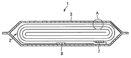
- FIG. 1 is a schematic cross-sectional view of a flat-type nonaqueous electrolyte battery 1.
- FIG. 2 is an enlarged cross-sectional view of a portion A in FIG.
- the nonaqueous electrolyte battery 1 includes a wound electrode group 2.
- the wound electrode group 2 is housed in the exterior member 3.
- the exterior member 3 is further filled with a nonaqueous electrolyte (not shown).
- the wound electrode group 2 includes a positive electrode 4, a negative electrode 5, and a separator 6, as shown in FIG.
- the wound electrode group 2 is formed by laminating the positive electrode 4 and the negative electrode 5 with the separator 6 interposed between them and winding them into a flat shape.
- a positive electrode terminal 7 is electrically connected to the positive electrode 4
- a negative electrode terminal 8 is electrically connected to the negative electrode 5.
- the exterior member 3 is a laminated film exterior bag.
- the electrode group 2 and the non-aqueous electrolyte are sealed by heat-sealing the opening of the laminated film exterior bag with the positive electrode terminal 7 and the negative electrode terminal 8 extended.
- the exterior member is not limited to a laminate film, and for example, a metal can can be used.
- the positive electrode 4 includes a positive electrode current collector 4a and a positive electrode active material layer 4b.
- the positive electrode active material layer 4b includes a positive electrode active material, and optionally a conductive agent and a binder.
- the positive electrode active material layer 4b is provided on one side or both sides of the positive electrode current collector 4a.
- a lithium transition metal composite oxide can be used as the positive electrode active material contained in the positive electrode active material layer 4b.
- a lithium transition metal composite oxide can be used. Examples include LiCoO 2 , Li 1 + a (Mn, Ni, Co) 1-a O 2 (0.0 ⁇ a ⁇ 0.2), Li 1 + b Ni 1-bc M1 c O 2 (0.0 ⁇ b ⁇ 0.2 , 0.0 ⁇ c ⁇ 0.4, M1 is at least one element selected from Co, Al and Fe), Li 1 + d Mn 2-de M2 e O 4 (0 ⁇ d ⁇ 0.3, 0 ⁇ e ⁇ 0.3 , M2 is Mg, Al, Fe, at least one element selected from Co and Ni), LiM3PO 4 (M3 is at least one element selected from Fe, Co and Ni) are included. These composite oxides may be used alone or in combination of two or more.
- the conductive agent is used to suppress the contact resistance between the active material and the current collector.
- Examples include carbonaceous materials such as acetylene black, carbon black and graphite.
- the binder is used to bind the active material and the conductive agent.
- examples thereof include polytetrafluoroethylene (PTFE), polyvinylidene fluoride (PVdF), and fluorine-based rubber.
- the mixing ratio of the positive electrode active material, the conductive agent, and the binder is 80% by mass to 95% by mass for the positive electrode active material, 3% by mass to 18% by mass for the conductive agent, and 2% by mass to 17% by mass for the binder. % Or less is preferable.
- the conductive agent is contained in an amount of 3% by mass or more, the above-described effects can be obtained.
- the binder is contained in an amount of 2% by mass or more, sufficient electrode strength can be obtained, and when it is contained in the range of 17% by mass or less, the amount of the insulator can be reduced and the internal resistance can be reduced.
- the positive electrode current collector 4a is preferably an aluminum foil or an aluminum alloy foil containing one or more elements selected from the group consisting of Mg, Ti, Zn, Mn, Fe, Cu and Si.
- the positive electrode is prepared by suspending a positive electrode active material, a conductive agent, and a binder in a commonly used solvent to prepare a slurry, applying the slurry to a positive electrode current collector, drying, and forming a positive electrode layer It can be produced by rolling.
- N-methylethylpyrrolidone can be used as the solvent.
- the ratio of the total mass of the positive electrode active material, the conductive agent and the binder to the mass of the solvent is preferably in the range of 50:50 to 80:20.
- the negative electrode 5 includes a negative electrode current collector 5a and a negative electrode active material layer 5b.
- the negative electrode active material layer 5b includes a negative electrode active material, and optionally a conductive agent and a binder.
- the negative electrode active material layer 5b is provided on one side or both sides of the negative electrode current collector 5a.
- FIG. 3 is a perspective view showing an example of the negative electrode.
- FIG. 3 shows a part of the negative electrode 5 in which the negative electrode active material layer 5b is provided on both surfaces of the negative electrode current collector 5a.
- a surface that is one surface of the negative electrode current collector 5a and faces the positive electrode 4 is referred to as a second surface.
- First negative electrode active material layer 5b 1 is provided on a portion of the second surface.
- Second negative electrode active material layer 5b 2 are provided on a portion of the back surface of the second surface of the negative electrode current collector 5a.
- Negative electrode current collector 5a is first anode active and a second coating portion 5c material layer 5b 1 is provided, and a second coating not the anode active material layer 5b 1 of the first are present Part 5c and a second non-coated part 5d adjacent to each other in a direction parallel to the second surface.
- the second non-coated portion 5d is adjacent to at least one edge of the negative electrode current collector 5a and extends along the at least one edge.
- the second non-coated portion 5d functions as a negative electrode tab.
- the negative electrode terminal 8 shown in FIG. 1 is connected to the second non-coated portion 5d directly or via a conductive member such as a lead. Thereby, the negative electrode 5 and the negative electrode terminal 8 are electrically connected.
- the length from the boundary between the second coating part 5c and the second non-coating part 5d to the edge where the second non-coating part 5d is adjacent is referred to as L2.
- This L2 is in the range of 5 mm to 20 mm.
- the connection area between the second non-coated portion 5d and the negative electrode terminal 8 or the conductive member can be increased, and the connection resistance can be reduced.
- the electrical resistance can be reduced.
- the fall of energy density can be prevented by making length L2 into 20 mm or less.
- the minimum value of the length from the boundary of the 2nd coating part 5c and the 2nd non-coating part 5d to the edge of a negative electrode collector is 5 mm or more, and the maximum value of this length is 20 mm or less It is.
- the density of the first negative electrode active material layer 5b1 is in the range of 2.1 g / cc or more and 2.4 g / cc or less.
- the density of the second negative electrode active material layer 5b 2 is also preferably within the above range.
- the density is a value calculated by measuring the thickness and area of the negative electrode active material layer, calculating the volume, and calculating the volume and mass. That is, the density referred to here is the volume when both the open holes communicating with the outside air in the negative electrode active material layer and the closed holes not communicating with the outside air are included in the volume. Density, so-called bulk density.
- the ratio W1 / W2 of the mass W1 per unit area of the second coated part 5c to the mass W2 per unit area of the second non-coated part 5d is 0.997 or more and 1 or less.
- the mass ratio W1 / W2 is calculated from the result of measuring the mass per unit area (for example, g / cm 2 ) for each of the second coated part 5c and the second non-coated part 5d.
- the mass ratio (W1 / W2) within the above range, the difference in mass per unit area between the second coated portion 5c and the second non-coated portion 5d can be reduced. For this reason, it is possible to reduce the distortion of the electrode.
- the distortion of the electrodes is small, a gap is hardly generated between the electrodes when the electrodes are wound or stacked. As a result, it is possible to reduce the electrical resistance inside the battery. Thereby, a negative electrode with small internal resistance can be provided.
- the second negative electrode active material layer 5b 2 is preferably provided only in the second coating part. That is, the first negative electrode active material layer 5b 1 second and the negative electrode active material layer 5b 2 is preferably provided at a position facing each other across the anode current collector 5a.
- a titanium-containing metal composite oxide can be used as the negative electrode active material contained in the negative electrode active material layer 5b.
- examples thereof include a lithium titanium oxide and a titanium-based oxide that does not contain lithium during synthesis but can contain lithium by charge and discharge.
- lithium titanium oxide examples include Li 4 + x Ti 5 O 12 (0 ⁇ x ⁇ 3) having a spinel structure and Li 2 + y Ti 3 O 7 (0 ⁇ y ⁇ 3) having a ramsteride structure. included.
- titanium-based oxides include TiO 2 and metal composite oxides containing Ti and at least one element selected from the group consisting of P, V, Sn, Cu, Ni, Co, and Fe. .
- TiO 2 has an anatase structure, and preferably has a low crystallinity and a heat treatment temperature of 300 to 500 ° C.
- metal composite oxides include TiO 2 -P 2 O 5 , TiO 2 -V 2 O 5 , TiO 2 -P 2 O 5 -SnO 2 , and TiO 2 -P 2 O 5 -MeO (Me At least one element selected from the group consisting of Cu, Ni, Co and Fe).
- the metal composite oxide is preferably one in which a crystal phase and an amorphous phase coexist, or one having a microstructure in which an amorphous phase exists alone.
- the metal composite oxide having such a microstructure can greatly improve the cycle performance.
- the negative electrode active material is selected from lithium titanium oxide and a metal composite oxide containing Ti and at least one element selected from the group consisting of P, V, Sn, Cu, Ni, Co, and Fe. Is more preferable.
- the conductive agent is used to suppress the contact resistance between the active material and the current collector.
- Examples include carbonaceous materials such as acetylene black, carbon black and graphite.
- the binder is used to bind the active material and the conductive agent.
- examples thereof include polytetrafluoroethylene (PTFE), polyvinylidene fluoride (PVdF), fluorine-based rubber, and styrene butadiene rubber.
- the compounding ratio of the negative electrode active material, the conductive agent and the binder is such that the negative electrode active material is 70% by mass to 96% by mass, the conductive agent is 2% by mass to 28% by mass, and the binder is 2% by mass to 28% by mass. % Or less is preferable.
- the conductive agent By containing 2% by mass or more of the conductive agent, the current collecting performance of the negative electrode layer can be improved, and the large current characteristics of the battery can be improved.
- the binder is contained in an amount of 2% by mass or more, the binding property between the negative electrode layer and the negative electrode current collector can be improved, and the cycle characteristics can be improved.
- the conductive agent and the binder are each preferably contained in a range of 28% by mass or less.
- the negative electrode current collector 5a is preferably an aluminum foil, an aluminum alloy foil containing one or more elements selected from the group consisting of Mg, Ti, Zn, Mn, Fe, Cu and Si, or a copper foil.
- An aluminum foil or an aluminum alloy foil as described above is more preferable because it is electrochemically stable in a potential range nobler than 1.0 V.
- a negative electrode active material a negative electrode active material, a conductive agent, and a binder are suspended in a solvent to prepare a slurry.
- a solvent for example, N-methylethylpyrrolidone can be used as the solvent.
- the mixing ratio of the total mass of the negative electrode active material, the conductive agent and the binder to the mass of the solvent is preferably in the range of 50:50 to 80:20.
- the slurry is applied to one or both sides of the negative electrode current collector and dried to form a negative electrode active material layer.
- the slurry is applied to the negative electrode current collector, leaving a non-coated part continuous with a certain width.
- the second non-coated portion is preferably adjacent to the edge along the longitudinal direction of the negative electrode current collector. Or two 2nd non-coating parts may be provided and each may adjoin both the edges along the longitudinal direction of a negative electrode collector.
- the length of the second non-coated part is adjusted within the range of 5 mm or more and 20 mm or less.
- the length of the second non-coated portion refers to the edge of the negative electrode current collector adjacent to the second non-coated portion from the boundary between the second coated portion and the second non-coated portion. Is the length. In the case of the negative electrode used for the wound electrode group, this length refers to the length in the direction orthogonal to the longitudinal direction.
- the negative electrode current collector on which the negative electrode active material layer is formed is rolled so that the density of the negative electrode active material layer is in the range of 2.1 g / cc or more and 2.4 g / cc or less. Rolling can be performed using a roller press.
- the negative electrode current collector is also rolled together with the negative electrode active material layer.
- the roller since the diameter of the roller is constant, the roller does not contact the second non-coated portion where the active material layer is not coated. Therefore, the second coated portion coated with the active material layer is rolled to reduce the mass W1 per unit area, while the second non-coated portion is not rolled and the mass W2 per unit area is reduced. It does not change.
- the mass W1 per unit area of the second coated part is smaller than the mass W2 per unit area of the second non-coated part. That is, the mass ratio (W1 / W2) is less than 1.0, for example, about 0.995. This mass ratio (W1 / W2) is difficult to be set to 0.997 or more even when, for example, rolling is performed using a roller having a diameter exceeding 400 mm.
- the mass ratio (W1 / W2) can be set to 0.997 or more by extending the second non-coated portion to reduce the mass per unit area (W2).
- the stretching of the second non-coated portion can be realized by subjecting the entire negative electrode to a tensile treatment. In the tensile treatment, tension is applied to the entire negative electrode in a direction parallel to the boundary between the second coated part and the second non-coated part. By this tensile treatment, it is possible to selectively stretch the non-coated portion.
- the second non-coated portion is selectively stretched because the second coated portion is rolled while the second non-coated portion is not rolled, so that it is uniform throughout the negative electrode. It is considered that this is because the tension is concentrated on the second non-coated portion even when tension is applied.
- an aluminum foil generally used as a current collector is stretched when a tension corresponding to approximately 100 N / mm 2 is applied in a direction perpendicular to the cross section. Therefore, in order to stretch an aluminum foil having a thickness of 15 ⁇ m, a tension of about 1500 N / m is required.
- the second non-coated portion can be stretched even with a tension of about 300 N / m. This also shows that the second non-coated portion is selectively stretched even when a uniform tension is applied to the entire negative electrode.
- the non-coated portion can be stretched with a tension of about 300 N / m, so that the electrode can be prevented from breaking.
- the tensile treatment can be performed using, for example, a rewinding device including a winding device and a winding device.
- a rewinding device including a winding device and a winding device.
- the tension T applied to the electrode can be controlled.
- the electrode after the rolling process is passed through a rewinding device, and the tensioning process is performed by rolling and winding the electrode while controlling the tension T.
- the tension T is preferably in the range of 100 N / m to 600 N / m. By giving a tension in this range, the first non-coated portion can be stretched without breaking the electrode, and the mass ratio (W1 / W2) can be 0.997 or more.
- the heating temperature is preferably 60 ° C. or higher and 140 ° C. or lower. The above effects can be obtained by heating to 60 ° C. or higher. Further, by heating at 140 ° C. or lower, it is possible to prevent the binder contained in the active material layer from being deteriorated at a high temperature and deteriorating battery performance.
- the heating temperature is more preferably 100 ° C. or higher and 140 ° C. or lower. It can heat using warm air, an infrared heater, or an electromagnetic induction heater. Alternatively, it can be overheated by bringing the electrode into contact with a heated roller.
- the tension T is preferably in the range of 50 N / m to 400 N / m.
- Nonaqueous electrolyte a liquid non-aqueous electrolyte or a gel-like non-aqueous electrolyte can be used.
- the liquid non-aqueous electrolyte can be prepared by dissolving the electrolyte in an organic solvent.
- the gel-like nonaqueous electrolyte can be prepared by combining a liquid electrolyte and a polymer material.
- the concentration of the electrolyte in the liquid non-aqueous electrolyte is preferably in the range of 0.5 mol / L to 2.5 mol / L.
- electrolytes examples include lithium perchlorate (LiClO 4 ), lithium hexafluorophosphate (LiPF 6 ), lithium tetrafluoroborate (LiBF 4 ), lithium arsenic hexafluoride (LiAsF 6 ), trifluorometa Lithium salts such as lithium sulfonate (LiCF 3 SO 3 ) and lithium bistrifluoromethylsulfonylimide [LiN (CF 3 SO 2 ) 2 ] and mixtures thereof are included.
- the electrolyte is preferably one that is not easily oxidized even at a high potential, and LiPF 6 is most preferred.
- organic solvents examples include propylene carbonate (PC), ethylene carbonate (EC), cyclic carbonates such as vinylene carbonate; Carbonates; tetrahydrofuran (THF), cyclic ethers such as 2methyltetrahydrofuran (2MeTHF), dioxolane (DOX); chain ethers such as dimethoxyethane (DME) and diethoxyethane (DEE); ⁇ -butyrolactone (GBL), Acetonitrile (AN) and sulfolane (SL) are included.
- PC propylene carbonate
- EC ethylene carbonate
- cyclic carbonates such as vinylene carbonate
- Carbonates tetrahydrofuran (THF)
- cyclic ethers such as 2methyltetrahydrofuran (2MeTHF)
- DOX dioxolane
- chain ethers such as dimethoxyethane (DME) and diethoxyethane (DEE)
- polymer material examples include polyvinylidene fluoride (PVdF), polyacrylonitrile (PAN), and polyethylene oxide (PEO).
- PVdF polyvinylidene fluoride
- PAN polyacrylonitrile
- PEO polyethylene oxide
- the non-aqueous electrolyte may be a room temperature molten salt (ionic melt) containing lithium ions, a polymer solid electrolyte, an inorganic solid electrolyte, or the like.
- the room temperature molten salt refers to a compound that can exist as a liquid at room temperature (15 to 25 ° C.) among organic salts composed of a combination of an organic cation and an anion.
- the room temperature molten salt includes a room temperature molten salt that exists alone as a liquid, a room temperature molten salt that becomes liquid when mixed with an electrolyte, and a room temperature molten salt that becomes liquid when dissolved in an organic solvent.
- the melting point of a room temperature molten salt used for a nonaqueous electrolyte battery is 25 ° C. or less.
- the organic cation generally has a quaternary ammonium skeleton.
- the polymer solid electrolyte is prepared by dissolving an electrolyte in a polymer material and solidifying it.
- the inorganic solid electrolyte is a solid material having lithium ion conductivity.
- a porous film formed from a material such as polyethylene, polypropylene, cellulose, and polyvinylidene fluoride (PVdF), a synthetic resin nonwoven fabric, and the like can be used.
- PVdF polyvinylidene fluoride
- a porous film made of polyethylene or polypropylene can be melted at a constant temperature to cut off the current. Therefore, those porous films are preferable from the viewpoint of improving safety.
- the porous film formed from cellulose can contain more electrolyte with the same thickness as the separator formed from other materials, the lithium ion conductivity in the electrolyte is relatively large. It is preferably used in a high-power non-aqueous electrolyte battery that requires a large current to flow.
- a bag-like container made of a laminated film or a metal container can be used as the exterior member.
- the thickness of the laminate film is preferably 0.5 mm or less, and more preferably 0.2 mm or less.
- the thickness of the metal container is preferably 1 mm or less, more preferably 0.5 mm or less, and further preferably 0.3 mm or less.
- the shape of the exterior member may be a flat type (thin type), a square type, a cylindrical type, a coin type, a button type, or the like.
- the exterior member may be, for example, a small battery exterior member that is loaded on a portable electronic device or the like, or a large battery exterior member that is loaded on a two-wheel to four-wheel automobile or the like, depending on the battery size.
- the laminate film a multilayer film in which a metal layer is interposed between resin layers is used.
- the metal layer is preferably an aluminum foil or an aluminum alloy foil for weight reduction.
- the resin layer is used to reinforce the metal layer.
- resins include polymeric materials such as polypropylene (PP), polyethylene (PE), nylon and polyethylene terephthalate (PET).
- PP polypropylene
- PE polyethylene
- PET polyethylene terephthalate
- the laminate film can be formed into the shape of an exterior member by sealing by heat sealing.
- Metal containers are made from aluminum or aluminum alloy.
- the aluminum alloy is preferably an alloy containing elements such as magnesium, zinc, and silicon.
- the alloy contains a transition metal such as iron, copper, nickel, or chromium, the content is preferably 1% by mass or less.
- a non-aqueous electrolyte secondary battery using a wound electrode group has been described as an example.
- the present invention is not limited to this, and a stacked electrode group may be used instead of the wound electrode group.
- the nonaqueous electrolyte battery of the second embodiment has the same configuration as that of the first embodiment except that a positive electrode described below is used.
- the positive electrode 4 includes a positive electrode current collector 4a and a positive electrode active material layer 4b.
- the positive electrode active material layer 4b includes a positive electrode active material, and optionally a conductive agent and a binder.
- the positive electrode active material layer 4b is provided on one side or both sides of the positive electrode current collector 4a.
- the positive electrode active material, the conductive agent and the binder, the blending ratio thereof, and the positive electrode current collector are the same as those described in the first embodiment.
- FIG. 4 is a perspective view showing an example of the positive electrode.
- FIG. 4 shows a part of the positive electrode 4 in which the positive electrode active material layer 4b is provided on both surfaces of the positive electrode current collector 4a.
- One surface of the positive electrode current collector 4a and the surface facing the negative electrode 5 is referred to as a first surface.
- a first positive electrode active material layer 4b 1 is provided on a part of the first surface.
- Second positive electrode active material layer 4b 2 is provided on a portion of the back surface of the first surface of the positive electrode current collector 4a.
- Cathode current collector 4a, the first and the coated portion 4c, the first positive electrode active material layer 4b 1 does not exist and the first coating of the first positive electrode active material layer 4b 1 provided Part 4c and first non-coated part 4d adjacent to each other in the direction parallel to the first surface.
- the first non-coated portion 4d is adjacent to at least one edge of the positive electrode current collector 4a and extends along the at least one edge.
- the first non-coated part 4d functions as a positive electrode tab.
- the positive terminal 7 shown in FIG. 1 is connected to the first non-coated portion 4d directly or via a conductive member such as a lead. Thereby, the positive electrode 4 and the positive electrode terminal 7 are electrically connected.
- the length from the boundary between the first coating part 4c and the first non-coating part 4d to the edge where the first non-coating part 4d is adjacent is referred to as L1.
- This L1 is in the range of 5 mm to 20 mm.
- the minimum value of the length from the boundary of the 1st coating part 4c and the 1st non-coating part 4d to the edge of a positive electrode electrical power collector is 5 mm or more, and the maximum value of this length is 20 mm or less It is.
- the density of the first positive electrode active material layer 4b1 is in the range of 3.1 g / cc to 3.4 g / cc.
- the density is a value calculated from the volume and mass obtained by measuring the thickness and area of the positive electrode active material layer and calculating the volume. That is, the density referred to here is the value obtained when the volume of both the open holes communicating with the outside air in the positive electrode active material layer and the isolated closed holes not communicating with the outside air are included in the volume. Density, so-called bulk density.
- the ratio W1 / W2 of the mass W1 per unit area of the first coating part 4c to the mass W2 per unit area of the first non-coating part 4d is 0.997 or more and 1 or less.
- the mass ratio W1 / W2 is calculated from the result of measuring the mass per unit area (for example, g / cm 2 ) for each of the first coated part 4c and the first non-coated part 4d.
- the second positive electrode active material layer 4b 2 is preferably provided only in the first coating part. That is, the first positive electrode active material layer 4b 1 and the second positive electrode active material layer 4b 2, is preferably provided in a position facing each other across the positive electrode current collector 4a.
- the mass ratio (W1 / W2) within the above range, the difference in mass per unit area between the first coated portion 4c and the first non-coated portion 4d can be reduced. For this reason, it is possible to reduce the distortion of the electrode.
- the distortion of the electrodes is small, a gap is hardly generated between the electrodes when the electrodes are wound or stacked. As a result, it is possible to reduce the electrical resistance inside the battery. Thereby, a positive electrode with small internal resistance can be provided.
- the large current characteristics of the nonaqueous electrolyte battery can be further improved.
- a positive electrode active material, a conductive agent, and a binder are suspended in a solvent to prepare a slurry.
- a solvent for example, N-methylethylpyrrolidone can be used as the solvent.
- the mixing ratio of the total mass of the positive electrode active material, the conductive agent and the binder to the mass of the solvent is preferably in the range of 50:50 to 80:20.
- the slurry is applied to one or both sides of the positive electrode current collector and dried to form a positive electrode active material layer.
- the slurry is applied to the positive electrode current collector, leaving the first non-coated portion continuous with a constant width.
- the first non-coated portion is preferably adjacent to the edge along the longitudinal direction of the positive electrode current collector.
- two 1st non-coating parts may be provided and may each adjoin to both the edges along the longitudinal direction of a positive electrode electrical power collector.
- the length of the 1st non-coating part is adjusted in the range of 5 mm or more and 20 mm or less.
- the length of the first non-coated portion refers to the edge of the positive electrode current collector adjacent to the first non-coated portion from the boundary between the first coated portion and the first non-coated portion. Is the length. In the case of the positive electrode used for the wound electrode group, this length refers to the length in the direction orthogonal to the longitudinal direction.
- the positive electrode current collector on which the positive electrode active material layer is formed is rolled so that the density of the positive electrode active material layer is in the range of 3.1 g / cc to 3.4 g / cc. Rolling can be performed using a roller press.
- the positive electrode current collector is also rolled together with the positive electrode active material layer.
- the roller since the diameter of the roller is constant, the roller does not contact the non-coated portion where the active material layer is not coated. Therefore, the coated portion coated with the active material layer is rolled to reduce the mass W1 per unit area, while the first non-coated portion is not rolled and the mass W2 per unit area does not change.
- the mass W1 per unit area of the first coated part is smaller than the mass W2 per unit area of the first non-coated part. That is, the mass ratio (W1 / W2) is less than 1.0, for example, about 0.995. This mass ratio (W1 / W2) is difficult to be set to 0.997 or more even when, for example, rolling is performed using a roller having a diameter exceeding 400 mm.
- the mass ratio (W1 / W2) can be set to 0.997 or more by extending the first non-coated portion to reduce the mass per unit area (W2).
- the stretching of the first non-coated portion can be realized by subjecting the entire positive electrode to a tensile treatment. In the tension treatment, tension is applied to the whole positive electrode in a direction parallel to the boundary between the first coated part and the first non-coated part. By this tensile treatment, the first non-coated portion can be selectively stretched.
- the tensile treatment can be performed in the same manner as the tensile treatment in the negative electrode manufacturing method of the first embodiment.
- the electrode group is composed of the positive electrode 4, the negative electrode 5, and the separator 6 as described above.
- the separator includes first and second portions spaced apart from each other and a third portion interposed between the first and second portions.
- the third part of the separator is interposed between the first coating part of the positive electrode and the second coating part of the negative electrode.
- the first non-coated portion of the positive electrode is preferably positioned so as to face the first portion of the separator
- the second non-coated portion of the negative electrode is preferably positioned so as to face the second portion of the separator.
- the first non-coated portion of the positive electrode is preferably located on the opposite side in the winding axis direction to the second non-coated portion of the negative electrode.
- LiCoO 2 was used as the positive electrode active material
- acetylene black and carbon black were used as the conductive agent
- polyvinylidene fluoride was used as the binder.
- Each was mixed at a mass ratio of 85: 5: 5: 5 and dispersed in an organic solvent to prepare a slurry.
- This slurry was applied to an aluminum foil having a thickness of 20 ⁇ m and dried to form an active material layer.
- the slurry was applied to the back side of the aluminum foil and dried to form an active material layer.
- the active material layers on both sides of the aluminum foil were formed so that their longitudinal sides coincided. Specifically, it formed so that the shift
- the aluminum foil having an active material layer on both sides obtained above was cut with a certain width to obtain a positive electrode before rolling in which a non-coated part with a width of 15 mm was present at one end in the longitudinal direction.
- the positive electrode before rolling was rolled using a roll press to obtain a positive electrode. In the rolling, the roll press load was adjusted so that the density of the active material layer was 3.2 g / cc.
- Li 4 Ti 5 O 12 was used as the negative electrode active material, carbon black was used as the conductive agent, and polyvinylidene fluoride was used as the binder.
- Each was mixed at a mass ratio of 85: 10: 5 and dispersed in an organic solvent to prepare a slurry.
- This slurry was applied to an aluminum foil having a thickness of 20 ⁇ m and dried to form an active material layer.
- the slurry was applied to the back side of the aluminum foil and dried to form an active material layer.
- the active material layers on both sides of the aluminum foil were formed so that their longitudinal sides coincided. Specifically, it formed so that the shift
- the aluminum foil having the active material layer on both sides obtained above was cut with a certain width to obtain a negative electrode before rolling in which a non-coated part with a width of 15 mm was present at one end in the longitudinal direction.
- the negative electrode before rolling was rolled using a roll press to obtain a negative electrode. In rolling, the load of the roll press was adjusted so that the density of the active material layer was 2.2 g / cc.
- ⁇ Preparation of nonaqueous electrolyte secondary battery> The positive electrode and the negative electrode manufactured as described above were laminated with a separator in between, and wound into a coil to obtain an electrode group.
- the non-coated portion of the positive electrode protruded from one end of the electrode group, and the non-coated portion of the negative electrode protruded from the other end of the electrode group.
- the non-coated portion of the positive electrode was bundled and the positive electrode terminal was ultrasonically bonded.
- the non-coated part of the negative electrode was bundled, and the negative electrode terminal was ultrasonically bonded.
- Aluminum plates were used for the positive and negative terminals.
- This electrode group was put in an aluminum laminate exterior member, and a nonaqueous electrolyte was injected and sealed to obtain a nonaqueous electrolyte secondary battery.
- the coating part was cut out from the positive electrode manufactured similarly to the positive electrode used for preparation of said nonaqueous electrolyte secondary battery.
- the active material layer on the surface of the coated part was removed with an organic solvent.
- the mass and area of the remaining aluminum foil were measured, and the mass W1 per unit area was calculated.
- the non-coating part was cut out, the mass and area were measured, and mass W2 per unit area was computed.
- the mass ratio (W1 / W2) of the positive electrode was 0.995.
- the coated part was cut out from the negative electrode produced in the same manner as the negative electrode used for the production of the nonaqueous electrolyte secondary battery.
- the active material layer on the surface of the coated part was removed with an organic solvent.
- the mass and area of the remaining aluminum foil were measured, and the mass W1 per unit area was calculated.
- the non-coating part was cut out, the mass and area were measured, and mass W2 per unit area was computed.
- the mass ratio (W1 / W2) of the negative electrode was 0.995.
- ⁇ Discharge test> A discharge test was performed using the non-aqueous electrolyte secondary battery produced as described above. The battery was charged to half the capacity. Thereafter, the battery was discharged at a current of 20 C, the product of the voltage 10 seconds after the start of discharge and the discharge current was taken, and the output was calculated.
- Example 1 After producing a positive electrode in the same manner as in Comparative Example 1, a tensile treatment was performed. The tensile treatment was performed by passing the positive electrode through an electrode rewinding device equipped with a rolling-out device and a winding device, and changing the tension by setting the tension to 500 N / m. The negative electrode and the nonaqueous electrolyte secondary battery were produced in the same manner as in Comparative Example 1. Measurements and discharge tests were performed using this battery. Table 1 shows the density and mass ratio (W1 / W2) of the active material layers of the positive electrode and the negative electrode, and the length of the non-coated part.
- Example 2 After producing the negative electrode in the same manner as in Comparative Example 1, a tensile treatment was performed. The tensile treatment was performed by passing the negative electrode through an electrode rewinding device equipped with a rolling-out device and a winding device, and changing the tension while setting the tension to 500 N / m. The positive electrode and the nonaqueous electrolyte secondary battery were produced in the same manner as in Comparative Example 1. Measurements and discharge tests were performed using this battery. Table 1 shows the density and mass ratio (W1 / W2) of the active material layers of the positive electrode and the negative electrode, and the length of the non-coated part.
- Example 3 A nonaqueous electrolyte secondary battery was produced in the same manner as in Comparative Example 1 except that the positive electrode produced in the same manner as in Example 1 and the negative electrode produced in the same manner as in Example 2 were used. Measurements and discharge tests were performed using this battery. Table 1 shows the density and mass ratio (W1 / W2) of the active material layers of the positive electrode and the negative electrode, and the length of the non-coated part.
- Comparative Example 2 A nonaqueous electrolyte secondary battery was produced in the same manner as in Comparative Example 1 except that the lengths of the non-coated portions of the positive electrode and the negative electrode were each 10 mm. Measurements and discharge tests were performed using this battery. Table 1 shows the density and mass ratio (W1 / W2) of the active material layers of the positive electrode and the negative electrode, and the length of the non-coated part.
- Example 4 A nonaqueous electrolyte secondary battery was produced in the same manner as in Comparative Example 1 except that the positive electrode of Comparative Example 2 was subjected to a tensile treatment. Measurements and discharge tests were performed using this battery. Table 1 shows the density and mass ratio (W1 / W2) of the active material layers of the positive electrode and the negative electrode, and the length of the non-coated part. Tensile treatment was performed as described in Example 1.
- Example 5 A nonaqueous electrolyte secondary battery was produced in the same manner as in Comparative Example 1 except that the negative electrode of Comparative Example 2 was subjected to a tensile treatment. Measurements and discharge tests were performed using this battery. Table 1 shows the density and mass ratio (W1 / W2) of the active material layers of the positive electrode and the negative electrode, and the length of the non-coated part. Tensile treatment was performed as described in Example 1.
- Example 6 A nonaqueous electrolyte secondary battery was produced in the same manner as in Comparative Example 1 except that each of the positive electrode and the negative electrode in Comparative Example 2 was subjected to a tensile treatment. Measurements and discharge tests were performed using this battery. Table 1 shows the density and mass ratio (W1 / W2) of the active material layers of the positive electrode and the negative electrode, and the length of the non-coated part. Tensile treatment was performed as described in Example 1.
- Comparative Example 3 A nonaqueous electrolyte secondary battery was produced in the same manner as in Comparative Example 1 except that the lengths of the non-coated portions of the positive electrode and the negative electrode were each 5 mm. Measurements and discharge tests were performed using this battery. Table 1 shows the density and mass ratio (W1 / W2) of the active material layers of the positive electrode and the negative electrode, and the length of the non-coated part.
- Example 7 A nonaqueous electrolyte secondary battery was produced in the same manner as in Comparative Example 1 except that the positive electrode of Comparative Example 3 was subjected to a tensile treatment. Measurements and discharge tests were performed using this battery. Table 1 shows the density and mass ratio (W1 / W2) of the active material layers of the positive electrode and the negative electrode, and the length of the non-coated part. Tensile treatment was performed as described in Example 1.
- Example 8 A nonaqueous electrolyte secondary battery was produced in the same manner as in Comparative Example 1 except that the negative electrode of Comparative Example 3 was subjected to a tensile treatment. Measurements and discharge tests were performed using this battery. Table 1 shows the density and mass ratio (W1 / W2) of the active material layers of the positive electrode and the negative electrode, and the length of the non-coated part. Tensile treatment was performed as described in Example 1.
- Example 9 A nonaqueous electrolyte secondary battery was produced in the same manner as in Comparative Example 1 except that each of the positive electrode and the negative electrode in Comparative Example 3 was subjected to a tensile treatment. Measurements and discharge tests were performed using this battery. Table 1 shows the density and mass ratio (W1 / W2) of the active material layers of the positive electrode and the negative electrode, and the length of the non-coated part. Tensile treatment was performed as described in Example 1.
- Comparative Example 4 A nonaqueous electrolyte secondary battery was produced in the same manner as in Comparative Example 1 except that the lengths of the non-coated portions of the positive electrode and the negative electrode were each 2 mm. Measurements and discharge tests were performed using this battery. Table 1 shows the density and mass ratio (W1 / W2) of the active material layers of the positive electrode and the negative electrode, and the length of the non-coated part.
- Comparative Example 5 A nonaqueous electrolyte secondary battery was produced in the same manner as in Comparative Example 1 except that the positive electrode of Comparative Example 4 was subjected to a tensile treatment. Measurements and discharge tests were performed using this battery. Table 1 shows the density and mass ratio (W1 / W2) of the active material layers of the positive electrode and the negative electrode, and the length of the non-coated part. Tensile treatment was performed as described in Example 1.
- Comparative Example 6 A nonaqueous electrolyte secondary battery was produced in the same manner as in Comparative Example 1 except that the negative electrode of Comparative Example 4 was subjected to a tensile treatment. Measurements and discharge tests were performed using this battery. Table 1 shows the density and mass ratio (W1 / W2) of the active material layers of the positive electrode and the negative electrode, and the length of the non-coated part. Tensile treatment was performed as described in Example 1.
- Comparative Example 7 A nonaqueous electrolyte secondary battery was produced in the same manner as in Comparative Example 1 except that each of the positive electrode and the negative electrode in Comparative Example 4 was subjected to a tensile treatment. Measurements and discharge tests were performed using this battery. Table 1 shows the density and mass ratio (W1 / W2) of the active material layers of the positive electrode and the negative electrode, and the length of the non-coated part. Tensile treatment was performed as described in Example 1.
- Comparative Example 8 A nonaqueous electrolyte secondary battery was produced in the same manner as in Comparative Example 1 except that the density of the active material layers of the positive electrode and the negative electrode was changed by changing the load of the roll press. Measurements and discharge tests were performed using this battery. Table 1 shows the density and mass ratio (W1 / W2) of the active material layers of the positive electrode and the negative electrode, and the length of the non-coated part.
- Example 10 A nonaqueous electrolyte secondary battery was produced in the same manner as in Comparative Example 1 except that the positive electrode of Comparative Example 8 was subjected to a tensile treatment. Measurements and discharge tests were performed using this battery. Table 1 shows the density and mass ratio (W1 / W2) of the active material layers of the positive electrode and the negative electrode, and the length of the non-coated part. Tensile treatment was performed as described in Example 1.
- Example 11 A nonaqueous electrolyte secondary battery was produced in the same manner as in Comparative Example 1 except that the negative electrode of Comparative Example 8 was subjected to a tensile treatment. Measurements and discharge tests were performed using this battery. Table 1 shows the density and mass ratio (W1 / W2) of the active material layers of the positive electrode and the negative electrode, and the length of the non-coated part. Tensile treatment was performed as described in Example 1.
- Example 12 A nonaqueous electrolyte secondary battery was produced in the same manner as in Comparative Example 1 except that each of the positive electrode and the negative electrode in Comparative Example 8 was subjected to a tensile treatment. Measurements and discharge tests were performed using this battery. Table 1 shows the density and mass ratio (W1 / W2) of the active material layers of the positive electrode and the negative electrode, and the length of the non-coated part. Tensile treatment was performed as described in Example 1.
- Comparative Example 9 A nonaqueous electrolyte secondary battery was produced in the same manner as in Comparative Example 1 except that the density of the active material layers of the positive electrode and the negative electrode was changed by changing the load of the roll press. Measurements and discharge tests were performed using this battery. Table 1 shows the density and mass ratio (W1 / W2) of the active material layers of the positive electrode and the negative electrode, and the length of the non-coated part.
- Comparative Example 10 A nonaqueous electrolyte secondary battery was produced in the same manner as in Comparative Example 1 except that the positive electrode of Comparative Example 9 was subjected to a tensile treatment. Measurements and discharge tests were performed using this battery. Table 1 shows the density and mass ratio (W1 / W2) of the active material layers of the positive electrode and the negative electrode, and the length of the non-coated part. Tensile treatment was performed as described in Example 1.
- Comparative Example 11 A nonaqueous electrolyte secondary battery was produced in the same manner as in Comparative Example 1 except that the negative electrode of Comparative Example 9 was subjected to a tensile treatment. Measurements and discharge tests were performed using this battery. Table 1 shows the density and mass ratio (W1 / W2) of the active material layers of the positive electrode and the negative electrode, and the length of the non-coated part. Tensile treatment was performed as described in Example 1.
- Comparative Example 12 A nonaqueous electrolyte secondary battery was produced in the same manner as in Comparative Example 1 except that each of the positive electrode and the negative electrode in Comparative Example 9 was subjected to a tensile treatment. Measurements and discharge tests were performed using this battery. Table 1 shows the density and mass ratio (W1 / W2) of the active material layers of the positive electrode and the negative electrode, and the length of the non-coated part. Tensile treatment was performed as described in Example 1.
- Comparative Example 13 A nonaqueous electrolyte secondary battery was produced in the same manner as in Comparative Example 1 except that the density of the active material layers of the positive electrode and the negative electrode was changed by changing the load of the roll press. Measurements and discharge tests were performed using this battery. Table 1 shows the density and mass ratio (W1 / W2) of the active material layers of the positive electrode and the negative electrode, and the length of the non-coated part.
- Example 13 A nonaqueous electrolyte secondary battery was produced in the same manner as in Comparative Example 1 except that the positive electrode of Comparative Example 13 was subjected to a tensile treatment. Measurements and discharge tests were performed using this battery. Table 1 shows the density and mass ratio (W1 / W2) of the active material layers of the positive electrode and the negative electrode, and the length of the non-coated part. Tensile treatment was performed as described in Example 1.
- Example 14 A nonaqueous electrolyte secondary battery was produced in the same manner as in Comparative Example 1 except that the negative electrode of Comparative Example 13 was subjected to a tensile treatment. Measurements and discharge tests were performed using this battery. Table 1 shows the density and mass ratio (W1 / W2) of the active material layers of the positive electrode and the negative electrode, and the length of the non-coated part. Tensile treatment was performed as described in Example 1.
- Example 15 A nonaqueous electrolyte secondary battery was produced in the same manner as in Comparative Example 1 except that each of the positive electrode and the negative electrode in Comparative Example 13 was subjected to a tensile treatment. Measurements and discharge tests were performed using this battery. Table 1 shows the density and mass ratio (W1 / W2) of the active material layers of the positive electrode and the negative electrode, and the length of the non-coated part. Tensile treatment was performed as described in Example 1.
- Comparative Example 14 A nonaqueous electrolyte secondary battery was produced in the same manner as in Comparative Example 1 except that the density of the active material layers of the positive electrode and the negative electrode was changed by changing the load of the roll press. Measurements and discharge tests were performed using this battery. Table 1 shows the density and mass ratio (W1 / W2) of the active material layers of the positive electrode and the negative electrode, and the length of the non-coated part.
- Comparative Example 15 A nonaqueous electrolyte secondary battery was produced in the same manner as in Comparative Example 1 except that LiNi 0.8 Co 0.17 Al 0.03 O 2 was used as the positive electrode active material. Measurements and discharge tests were performed using this battery. Table 1 shows the density and mass ratio (W1 / W2) of the active material layers of the positive electrode and the negative electrode, and the length of the non-coated part.
- Example 16 A nonaqueous electrolyte secondary battery was produced in the same manner as in Comparative Example 1 except that the positive electrode of Comparative Example 15 was subjected to a tensile treatment. Measurements and discharge tests were performed using this battery. Table 1 shows the density and mass ratio (W1 / W2) of the active material layers of the positive electrode and the negative electrode, and the length of the non-coated part. Tensile treatment was performed as described in Example 1.
- Example 17 A nonaqueous electrolyte secondary battery was produced in the same manner as in Comparative Example 1 except that the negative electrode of Comparative Example 15 was subjected to a tensile treatment. Measurements and discharge tests were performed using this battery. Table 1 shows the density and mass ratio (W1 / W2) of the active material layers of the positive electrode and the negative electrode, and the length of the non-coated part. Tensile treatment was performed as described in Example 1.
- Example 18 A nonaqueous electrolyte secondary battery was produced in the same manner as in Comparative Example 1 except that each of the positive electrode and the negative electrode in Comparative Example 15 was subjected to a tensile treatment. Measurements and discharge tests were performed using this battery. Table 1 shows the density and mass ratio (W1 / W2) of the active material layers of the positive electrode and the negative electrode, and the length of the non-coated part. Tensile treatment was performed as described in Example 1.
- Comparative Example 16 A nonaqueous electrolyte secondary battery was produced in the same manner as in Comparative Example 1 except that Li 1.1 Mn 1.8 Al 0.1 O 4 was used as the positive electrode active material. Measurements and discharge tests were performed using this battery. Table 1 shows the density and mass ratio (W1 / W2) of the active material layers of the positive electrode and the negative electrode, and the length of the non-coated part.
- Example 19 A nonaqueous electrolyte secondary battery was produced in the same manner as in Comparative Example 1 except that the positive electrode of Comparative Example 16 was subjected to a tensile treatment. Measurements and discharge tests were performed using this battery. Table 1 shows the density and mass ratio (W1 / W2) of the active material layers of the positive electrode and the negative electrode, and the length of the non-coated part. Tensile treatment was performed as described in Example 1.
- Example 20 A nonaqueous electrolyte secondary battery was produced in the same manner as in Comparative Example 1 except that the negative electrode of Comparative Example 16 was subjected to a tensile treatment. Measurements and discharge tests were performed using this battery. Table 1 shows the density and mass ratio (W1 / W2) of the active material layers of the positive electrode and the negative electrode, and the length of the non-coated part. Tensile treatment was performed as described in Example 1.
- Example 21 A nonaqueous electrolyte secondary battery was produced in the same manner as in Comparative Example 1 except that each of the positive electrode and the negative electrode in Comparative Example 16 was subjected to a tensile treatment. Measurements and discharge tests were performed using this battery. Table 1 shows the density and mass ratio (W1 / W2) of the active material layers of the positive electrode and the negative electrode, and the length of the non-coated part. Tensile treatment was performed as described in Example 1.
- Example 5 in which the negative electrode mass ratio (W1 / W2) was 0.997 or more had a higher output ratio than Comparative Example 2.
- Example 6 in which the mass ratio (W1 / W2) of each of the positive electrode and the negative electrode was 0.997 or more, the output ratio was higher than that in Example 5.
- Example 11 in which the negative electrode mass ratio (W1 / W2) was 0.997 or higher had a higher output ratio than Comparative Example 8.
- Example 12 in which the mass ratio (W1 / W2) of each of the positive electrode and the negative electrode was 0.997 or more, the output ratio was higher than that of Example 11.
- An electrode having a length of the non-coated portion of less than 5 mm has little distortion between the coated portion and the non-coated portion even by a rolling process in the manufacturing process. Therefore, it is difficult to obtain the effect of tension in this embodiment.
- a positive electrode in which the density of the positive electrode active material layer is less than 3.1 g / cc and a negative electrode in which the density of the negative electrode active material layer is less than 2.1 g / c are not rolled in the manufacturing process. Since the rolling is weak, there is little distortion between the coated part and the non-coated part of the current collector. Therefore, it is difficult to obtain the effect of tension in this embodiment.
- the mass ratio (W1 / W2) of the negative electrode is 0.997 or more, the length of the non-coated part is 5 mm or more, and the density of the negative electrode active material layer is 2.1 g / cc or more.
- the battery in the range of 4 g / cc or less has a higher output than the battery of the comparative example, and has been shown to have excellent large current characteristics.
- the mass ratio (W1 / W2) of the positive electrode is 0.997 or more
- the length of the non-coated part is 5 mm or more
- the density of the positive electrode active material layer is 3.1 g / cc or more and 3.4 g / It was shown that the battery having a range of cc or less has a higher output.
- SYMBOLS 1 Non-aqueous electrolyte battery, 2 ... Winding electrode group, 3 ... Exterior member, 4 ... Positive electrode, 4a ... Positive electrode collector, 4b ... Positive electrode active material layer, 4c ... 1st coating part, 4d ... 1st 5 ... negative electrode current collector, 5b ... negative electrode active material layer, 5c ... second coated part, 5d ... second non-coated part, 6 ... separator, 7 ... positive electrode Terminal, 8 ... negative terminal.
Abstract
実施形態によれば、正極及び負極を含む非水電解質二次電池が提供される。正極は第1面を有している正極集電体と正極活物質層とを含む。負極は正極の第1面と向き合った第2面を有している負極集電体と、第2面の一部の上に設けられた第1の負極活物質とを含む。負極集電体は、第1の負極活物質層が設けられた塗工部と、第1の負極活物質層が存在しておらず且つ塗工部と第2面に対して平行な方向に隣り合った非塗工部とを含む。非塗工部は、負極集電体の少なくとも一つの縁に隣接し且つ該少なくとも一つの縁に沿って延びる。塗工部と非塗工部との境界から負極集電体の少なくとも一つの縁までの長さは5mm以上20mm以下の範囲である。第1の負極活物質層の密度は2.1g/cc以上2.4g/cc以下の範囲である。非塗工部の単位面積当たりの質量W2に対する塗工部の単位面積当たりの質量W1の比W1/W2は0.997以上1以下である。
Description
本発明の実施形態は、非水電解質二次電池に関する。
近年、非水電解質二次電池をハイブリッド電気自動車用の電源として、或いは太陽光や風力などの自然エネルギーを使った発電機用の蓄電装置として使用することが検討されている。自動車用の電源の負荷は、自動車の走行状態などによって著しく変動する。発電機の発電量は、環境条件によって著しく変動する。そのため、非水電解質二次電池は大電流を短い時間で放出したり蓄電したりしなければならない場合がある。それ故、非水電解質二次電池は優れた大電流特性を有することが望まれる。しかしながら、電池の内部抵抗が大きい場合、大電流で充放電を行ったときに性能が低下するという問題がある。
内部抵抗が小さく、優れた大電流特性を有する非水電解質二次電池を提供する。
実施形態によれば、正極、負極及び非水電解質を含む非水電解質二次電池が提供される。正極は第1面を有している正極集電体と、第1面の一部の上に設けられた第1の正極活物質層とを含む。負極は第1面と向き合った第2面を有している負極集電体と、第2面の一部の上に設けられた第1の負極活物質とを含む。負極集電体は、第1の負極活物質層が設けられた第2の塗工部と、第1の負極活物質層が存在しておらず且つ第2の塗工部と第2面に対して平行な方向に隣り合った第2の非塗工部とを含む。第2の非塗工部は、負極集電体の少なくとも一つの縁に隣接し且つ該少なくとも一つの縁に沿って延びる。第2の塗工部と第2の非塗工部との境界から負極集電体の少なくとも一つの縁までの長さは5mm以上20mm以下の範囲である。第1の負極活物質層の密度は2.1g/cc以上2.4g/cc以下の範囲である。第2の非塗工部の単位面積当たりの質量W2に対する第2の塗工部の単位面積当たりの質量W1の比W1/W2は0.997以上1以下である。
以下、実施の形態について、図面を参照して説明する。
(第1実施形態)
図1は、扁平型の非水電解質電池1の断面模式図である。図2は図1のA部の拡大断面図である。非水電解質電池1は、捲回電極群2を備える。捲回電極群2は外装部材3に収納される。外装部材3内にはさらに非水電解質(図示せず)が充填される。
図1は、扁平型の非水電解質電池1の断面模式図である。図2は図1のA部の拡大断面図である。非水電解質電池1は、捲回電極群2を備える。捲回電極群2は外装部材3に収納される。外装部材3内にはさらに非水電解質(図示せず)が充填される。
捲回電極群2は、図2に示すように、正極4、負極5、及びセパレータ6から構成される。正極4と負極5を、セパレータ6を挟んで積層し、扁平形状に捲回することにより捲回電極群2が形成される。
図1に示すように、捲回電極群2の外周端近傍において、正極4には正極端子7が電気的に接続され、負極5には負極端子8が電気的に接続される。
外装部材3には、ラミネートフィルム製外装袋が用いられる。ラミネートフィルム製外装袋の開口部を、正極端子7及び負極端子8が延出した状態でヒートシールすることにより、電極群2及び非水電解質が密封される。なお、外装部材はラミネートフィルム製に限らず、例えば金属製の缶などを用いることもできる。
<正極>
図2に示すように、正極4は、正極集電体4a及び正極活物質層4bを備える。正極活物質層4bは、正極活物質、及び任意に導電剤及び結着剤を含む。正極活物質層4bは、正極集電体4aの片面又は両面に設けられる。
図2に示すように、正極4は、正極集電体4a及び正極活物質層4bを備える。正極活物質層4bは、正極活物質、及び任意に導電剤及び結着剤を含む。正極活物質層4bは、正極集電体4aの片面又は両面に設けられる。
正極活物質層4bに含まれる正極活物質としては、リチウム遷移金属複合酸化物を用いることができる。その例には、LiCoO2、Li1+a(Mn,Ni,Co)1-aO2(0.0<a<0.2)、Li1+bNi1-b-cM1cO2(0.0<b<0.2、0.0<c<0.4、M1はCo、Al及びFeから選択される少なくとも一つの元素である)、Li1+dMn2-d-eM2eO4(0<d<0.3、0<e<0.3、M2はMg、Al、Fe、Co及びNiから選択される少なくとも一つの元素である)、LiM3PO4(M3はFe、Co及びNiから選択される少なくとも一つの元素である)が含まれる。これらの複合酸化物は単独で用いてもよいが、複数種類を組合せて用いてもよい。
導電剤は活物質と集電体との接触抵抗を抑えるために用いられる。その例には、アセチレンブラック、カーボンブラック及び黒鉛のような炭素質物が含まれる。
結着剤は活物質と導電剤を結着させるために用いられる。その例には、ポリテトラフルオロエチレン(PTFE)、ポリフッ化ビニリデン(PVdF)及びフッ素系ゴムが含まれる。
正極活物質、導電剤及び結着剤の配合比は、正極活物質は80質量%以上95質量%以下、導電剤は3質量%以上18質量%以下、結着剤は2質量%以上17質量%以下の範囲にすることが好ましい。導電剤が3質量%以上含まれることにより上述した効果が得られ、18質量%以下の範囲で含まれることにより、高温保存下での導電剤表面での非水電解質の分解を低減することができる。結着剤が2質量%以上含まれることにより十分な電極強度が得られ、17質量%以下の範囲で含まれることにより、絶縁体の配合量を減少させ、内部抵抗を減少できる。
正極集電体4aは、アルミニウム箔又はMg、Ti、Zn、Mn、Fe、Cu及びSiから成る群より選択される一以上の元素を含むアルミニウム合金箔であることが好ましい。
正極は、例えば、正極活物質、導電剤及び結着剤を汎用されている溶媒に懸濁してスラリーを調製し、このスラリーを正極集電体に塗布し、乾燥し、正極層を形成した後、圧延することにより作製することができる。
溶媒には、例えばNメチルエチルピロリドンを用いることができる。正極活物質、導電剤及び結着剤の総質量と、溶媒の質量の比は、50:50から80:20の範囲であることが好ましい。
<負極>
負極5は、負極集電体5a及び負極活物質層5bを備える。負極活物質層5bは、負極活物質、及び任意に導電剤及び結着剤を含む。負極活物質層5bは、負極集電体5aの片面又は両面に設けられる。
負極5は、負極集電体5a及び負極活物質層5bを備える。負極活物質層5bは、負極活物質、及び任意に導電剤及び結着剤を含む。負極活物質層5bは、負極集電体5aの片面又は両面に設けられる。
図3は、負極の一例を示す斜視図である。図3は、負極集電体5aの両面に負極活物質層5bが設けられた負極5の一部を示している。負極集電体5aの一方の面であり、正極4と向かい合う面を第2面と称する。この第2面の一部の上に第1の負極活物質層5b1が設けられている。負極集電体5aの第2面の裏面の一部の上に第2の負極活物質層5b2が設けられている。
負極集電体5aは、第1の負極活物質層5b1が設けられた第2の塗工部5cと、第1の負極活物質層5b1が存在しておらず且つ第2の塗工部5cと第2面に対して平行な方向に隣り合った第2の非塗工部5dとを含む。
第2の非塗工部5dは、負極集電体5aの少なくとも一つの縁に隣接し且つ該少なくとも一つの縁に沿って延びている。第2の非塗工部5dは負極タブとして機能する。図1に示した負極端子8が第2の非塗工部5dに直接又はリードなどの導電部材を介して接続される。これにより、負極5と負極端子8とが電気的に接続される。
本実施形態において、第2の塗工部5cと第2の非塗工部5dとの境界から、第2の非塗工部5dが隣接している縁までの長さをL2と称する。このL2は5mm以上20mm以下の範囲である。長さL2を5mm以上にすることにより、第2の非塗工部5dと負極端子8又は導電部材との接続面積を大きくし、接続抵抗を減らすことができる。その結果、電気抵抗を低下させることが可能である。また、長さL2を20mm以下にすることにより、エネルギー密度の低下を防ぐことができる。なお、第2の塗工部5cと第2の非塗工部5dとの境界から負極集電体の縁までの長さの最小値が5mm以上であり、該長さの最大値が20mm以下である。
また、本実施形態において、第1の負極活物質層5b1の密度は、2.1g/cc以上2.4g/cc以下の範囲である。第1の負極活物質層5b1の密度を上記範囲内にすることにより、負極集電体5aと負極活物質の間の物理的接触を向上させることができる。その結果、内部抵抗を低下させることが可能である。第2の負極活物質層5b2の密度も上記範囲内であることが好ましい。
なお、ここでいう密度は負極活物質層の厚さと面積を計測して体積を算出し、その体積と質量から算出した値である。即ち、ここでいう密度は、負極活物質層内の外気と連通している開孔と、外気と連通しておらず孤立している閉孔とのいずれの空孔も体積に算入した場合の密度、いわゆる嵩密度を指す。
第2の非塗工部5dの単位面積当たりの質量W2に対する、第2の塗工部5cの単位面積当たりの質量W1の比W1/W2は0.997以上1以下である。質量比W1/W2は、第2の塗工部5cと第2の非塗工部5dのそれぞれについて単位面積当たりの質量(例えば、g/cm2)を測定して、その結果から算出する。
質量比(W1/W2)を上記範囲内にすることにより、第2の塗工部5cと第2の非塗工部5dの単位面積当たりの質量の相違を小さくすることができる。このため、電極の歪みを小さくすることが可能である。電極の歪みが小さいと、電極を捲回する際、或いは、スタック状に積み上げる際に、電極間に隙間が生じにくい。その結果、電池内部の電気抵抗を小さくすることが可能である。これにより、内部抵抗が小さい負極を提供することができる。
第2の負極活物質層5b2は、第2の塗工部にのみ設けられていることが好ましい。即ち、第1の負極活物質層5b1と第2の負極活物質層5b2とは、負極集電体5aを挟んで対向する位置に設けられることが好ましい。
負極活物質層5bに含まれる負極活物質としては、例えばチタン含有金属複合酸化物を用いることができる。その例には、リチウムチタン酸化物、及び、合成時はリチウムを含まないが充放電によりリチウムを含み得るチタン系酸化物が含まれる。
リチウムチタン酸化物の例には、スピネル構造を有するLi4+xTi5O12 (0≦x≦3)及びラムステライド構造を有するLi2+yTi3O7 (0≦y≦3)が含まれる。
チタン系酸化物の例には、TiO2、及び、P、V、Sn、Cu、Ni、Co及びFeから成る群より選択される少なくとも1つの元素とTiを含有する金属複合酸化物が含まれる。TiO2はアナターゼ構造を有するもので、熱処理温度が300~500℃の低結晶性のものが好ましい。
金属複合酸化物の例には、TiO2-P2O5、TiO2-V2O5、TiO2-P2O5-SnO2、及び、TiO2-P2O5-MeO(MeはCu、Ni、Co及びFeから成る群より選択される少なくとも1つの元素)が含まれる。金属複合酸化物は、結晶相とアモルファス相が共存したもの、又は、アモルファス相が単独で存在するミクロ構造を有するものであることが好ましい。このようなミクロ構造を有する金属複合酸化物は、サイクル性能を大幅に向上させることができる。
負極活物質は、リチウムチタン酸化物、及び、P、V、Sn、Cu、Ni、Co及びFeから成る群より選択される少なくとも1つの元素とTiを含有する金属複合酸化物から選択されることがより好ましい。
導電剤は活物質と集電体との接触抵抗を抑えるために用いられる。その例には、アセチレンブラック、カーボンブラック及び黒鉛のような炭素質物が含まれる。
結着剤は活物質と導電剤を結着させるために用いられる。その例には、ポリテトラフルオロエチレン(PTFE)、ポリフッ化ビニリデン(PVdF)、フッ素系ゴム及びスチレンブタジェンゴムが含まれる。
負極活物質、導電剤及び結着剤の配合比は、負極活物質は70質量%以上96質量%以下、導電剤は2質量%以上28質量%以下、結着剤は2質量%以上28質量%以下の範囲にすることが好ましい。導電剤が2質量%以上含まれることにより負極層の集電性能を向上させることができ、電池の大電流特性を向上させることができる。また、結着剤が2質量%以上含まれることにより、負極層と負極集電体の結着性を向上させ、サイクル特性を向上させることができる。一方、高容量化の観点から、導電剤及び結着剤は各々28質量%以下の範囲で含まれることが好ましい。
負極集電体5aは、アルミニウム箔、Mg、Ti、Zn、Mn、Fe、Cu及びSiから成る群より選択される一以上の元素を含むアルミニウム合金箔、又は銅箔であることが好ましい。アルミニウム箔又は上記のようなアルミニウム合金箔は、1.0Vよりも貴である電位範囲において電気化学的に安定であるため、より好ましい。
上記のような構成を有する負極を用いることにより、大電流特性に優れた非水電解質電池を提供することが可能である。
次に、負極の製造方法を説明する。
まず、負極活物質、導電剤及び結着剤を溶媒に懸濁してスラリーを調製する。溶媒には、例えばNメチルエチルピロリドンを用いることができる。負極活物質、導電剤及び結着剤の総質量と溶媒の質量との混合比は、50:50から80:20の範囲であることが好ましい。
まず、負極活物質、導電剤及び結着剤を溶媒に懸濁してスラリーを調製する。溶媒には、例えばNメチルエチルピロリドンを用いることができる。負極活物質、導電剤及び結着剤の総質量と溶媒の質量との混合比は、50:50から80:20の範囲であることが好ましい。
次に、スラリーを負極集電体の片面又は両面に塗布して乾燥し、負極活物質層を形成する。スラリーは、一定の幅で連続した非塗工部を残して負極集電体に塗布する。第2の非塗工部は、負極集電体の長手方向に沿った縁に隣接することが好ましい。或いは、第2の非塗工部は2つ設けられ、負極集電体の長手方向に沿った両方の縁にそれぞれが隣接してもよい。第2の非塗工部の長さは5mm以上20mm以下の範囲内に調整する。ここで、第2の非塗工部の長さとは、第2の塗工部と第2の非塗工部との境界から、第2の非塗工部が隣接する負極集電体の縁までの長さである。この長さは、捲回電極群に用いられる負極の場合、長手方向と直交する方向の長さを指す。
次いで、負極活物質層の密度が2.1g/cc以上2.4g/cc以下の範囲内になるように、負極活物質層が形成された負極集電体を圧延する。圧延はローラープレスを用いて実施することができる。
この圧延工程では、負極活物質層と共に負極集電体も圧延される。しかし、ローラーの直径は一定であるため、活物質層が塗工されていない第2の非塗工部にはローラーが接触しない。よって、活物質層が塗布された第2の塗工部は圧延されて、単位面積当たりの質量W1が減少する一方、第2の非塗工部は圧延されず、単位面積当たりの質量W2が変化しない。その結果、第2の塗工部の単位面積当たりの質量W1は、第2の非塗工部の単位面積当たりの質量W2よりも小さくなる。即ち、質量比(W1/W2)が1.0未満となり、例えば0.995程度になる。この質量比(W1/W2)は、例えば直径が400mmを超えるローラーを用いて圧延した場合であっても、0.997以上にすることは困難である。
質量比(W1/W2)が0.997未満である場合、第2の塗工部と第2の非塗工部との境界に応力が発生し、電極全体に歪みが生じる。このような歪んだ電極は、捲回する際、或いは、所定の大きさに切断してスタック状に積み上げる際に、電極間に隙間が生じ、正極及び負極の極板間が広くなる。その結果、電池内部の電気抵抗が増大し、大電流特性が低下する。
しかしながら、本実施形態によれば、第2の非塗工部を延伸させて単位面積当たりの質量(W2)を低下させることにより、質量比(W1/W2)を0.997以上にすることが可能である。第2の非塗工部の延伸は、負極全体を引張処理することにより実現することができる。引張処理では、負極全体に対して、第2の塗工部と第2の非塗工部との境界と平行な方向に張力を加える。この引張処理により、非塗工部を選択的に延伸させることが可能である。
第2の非塗工部が選択的に延伸されるのは、第2の塗工部は圧延されている一方で、第2の非塗工部は圧延されていないために、負極全体に均一に張力をかけても、張力が第2の非塗工部に集中するためであると考えられる。例えば、集電体として一般的に使われるアルミ箔は、断面と垂直方向におおむね100N/mm2に相当する張力を加えると延伸される。よって、厚さ15μmのアルミ箔を延伸するためには、約1500N/mの張力が必要である。しかしながら、本実施形態における引張処理では、300N/m程度の張力によっても第2の非塗工部を延伸させることが可能である。このことからも、負極全体に均一に張力をかけても、第2の非塗工部が選択的に延伸されることが示されている。
また、本実施形態によれば、300N/m程度の張力によって非塗工部を延伸させることができるため、電極が破断することを防ぐことができる。
引張処理は、例えば、捲き出し装置と巻き取り装置とを備えた巻き替え装置を用いて実施することができる。巻き出し装置のブレーキ力と巻き取り装置の巻き取り力とを調整することにより、電極に与える張力Tを制御することができる。圧延処理後の電極を巻き替え装置に通して、張力Tを制御しながら捲き出し及び巻き取りすることにより、引張処理を行う。張力Tは、100N/mから600N/mの範囲であることが好ましい。この範囲の張力を与えることにより、電極を破断することなく第1の非塗工部を延伸することができ、質量比(W1/W2)を0.997以上にすることができる。
引張処理を行う際に、第2の非塗工部を加熱してもよい。加熱することによって、塑性変形に必要な応力が100N/mm2よりも小さくなるため、より小さい張力Tで第2の非塗工部を延伸することができる。加熱温度は60℃以上140℃以下であることが好ましい。60℃以上に加熱することにより上記効果を得ることができる。また、140℃以下で加熱することにより、活物質層に含まれる結着剤が高温で変質して電池性能を低下させることを防ぐことができる。加熱温度は100℃以上140℃以下であることがより好ましい。温風、赤外線ヒーター又は電磁誘導ヒーターなどを用いて加熱することができる。或いは、加熱したローラーに電極を接触させることによっても過熱することができる。加熱して引張処理を行う場合は、張力Tは、50N/mから400N/mの範囲であることが好ましい。
<非水電解質>
非水電解質として、液状非水電解質、又はゲル状非水電解質を用いることができる。液状非水電解質は、電解質を有機溶媒に溶解することにより調製できる。ゲル状非水電解質は、液状電解質と高分子材料を複合化することにより調製できる。
非水電解質として、液状非水電解質、又はゲル状非水電解質を用いることができる。液状非水電解質は、電解質を有機溶媒に溶解することにより調製できる。ゲル状非水電解質は、液状電解質と高分子材料を複合化することにより調製できる。
液状非水電解質における電解質の濃度は、0.5mol/L以上2.5mol/L以下の範囲であることが好ましい。
電解質の例には、過塩素酸リチウム(LiClO4)、六フッ化リン酸リチウム(LiPF6)、四フッ化ホウ酸リチウム(LiBF4)、六フッ化砒素リチウム(LiAsF6)、トリフルオロメタスルホン酸リチウム(LiCF3SO3)、及びビストリフルオロメチルスルホニルイミドリチウム[LiN(CF3SO2)2]のようなリチウム塩、及び、これらの混合物が含まれる。電解質は高電位でも酸化し難いものであることが好ましく、LiPF6が最も好ましい。
有機溶媒の例には、プロピレンカーボネート(PC)、エチレンカーボネート(EC)、ビニレンカーボネートのような環状カーボネート;ジエチルカーボネート(DEC)、ジメチルカーボネート(DMC)、メチルエチルカーボネート(MEC)のような鎖状カーボネート;テトラヒドロフラン(THF)、2メチルテトラヒドロフラン(2MeTHF)、ジオキソラン(DOX)のような環状エーテル;ジメトキシエタン(DME)、ジエトキシエタン(DEE)のような鎖状エーテル;γ-ブチロラクトン(GBL)、アセトニトリル(AN)、及びスルホラン(SL)が含まれる。これらの有機溶媒は、単独で、又は混合溶媒として用いることができる。
高分子材料の例には、ポリフッ化ビニリデン(PVdF)、ポリアクリロニトリル(PAN)、及び、ポリエチレンオキサイド(PEO)が含まれる。
また或いは、非水電解質には、リチウムイオンを含有した常温溶融塩(イオン性融体)、高分子固体電解質、無機固体電解質等を用いてもよい。
常温溶融塩は、有機物カチオンとアニオンの組合せからなる有機塩の内、常温(15~25℃)で液体として存在しうる化合物を指す。常温溶融塩には、単体で液体として存在する常温溶融塩、電解質と混合させることで液体となる常温溶融塩、有機溶媒に溶解させることで液体となる常温溶融塩が含まれる。一般に、非水電解質電池に用いられる常温溶融塩の融点は、25℃以下である。また、有機物カチオンは、一般に4級アンモニウム骨格を有する。
高分子固体電解質は、電解質を高分子材料に溶解し、固体化することによって調製される。
無機固体電解質は、リチウムイオン伝導性を有する固体物質である。
無機固体電解質は、リチウムイオン伝導性を有する固体物質である。
<セパレータ>
セパレータとしては、例えば、ポリエチレン、ポリプロピレン、セルロース及びポリフッ化ビニリデン(PVdF)などの材料から形成された多孔質フィルム、合成樹脂製不織布等を用いることができる。中でも、ポリエチレン又はポリプロピレンからなる多孔質フィルムは、一定温度において溶融し、電流を遮断できる。それ故、それらの多孔質フィルムは安全性向上の観点から好ましい。
セパレータとしては、例えば、ポリエチレン、ポリプロピレン、セルロース及びポリフッ化ビニリデン(PVdF)などの材料から形成された多孔質フィルム、合成樹脂製不織布等を用いることができる。中でも、ポリエチレン又はポリプロピレンからなる多孔質フィルムは、一定温度において溶融し、電流を遮断できる。それ故、それらの多孔質フィルムは安全性向上の観点から好ましい。
また、セルロースから形成された多孔質フィルムは、他の材質から形成されたセパレータに比べて同じ厚さでより多くの電解質を含むことができるため、電解質中のリチウムイオン伝導度が相対的に大きく、大電流を流す必要のある高出力型の非水電解質電池において好適に用いられる。
<外装部材>
外装部材として、ラミネートフィルム製の袋状容器又は金属製容器を使用することができる。ラミネートフィルムの厚さは0.5mm以下であることが好ましく、0.2mm以下であることがより好ましい。金属製容の厚さは1mm以下であることが好ましく、0.5mm以下であることがより好ましく、0.3mm以下であることがさらに好ましい。
外装部材として、ラミネートフィルム製の袋状容器又は金属製容器を使用することができる。ラミネートフィルムの厚さは0.5mm以下であることが好ましく、0.2mm以下であることがより好ましい。金属製容の厚さは1mm以下であることが好ましく、0.5mm以下であることがより好ましく、0.3mm以下であることがさらに好ましい。
外装部材の形状は、扁平型(薄型)、角型、円筒型、コイン型、ボタン型等であってよい。外装部材は、電池寸法に応じて、例えば携帯用電子機器等に積載される小型電池用外装部材、二輪乃至四輪の自動車等に積載される大型電池用外装部材であってよい。
ラミネートフィルムは、樹脂層間に金属層が介在した多層フィルムが用いられる。金属層は、軽量化のためにアルミニウム箔もしくはアルミニウム合金箔であることが好ましい。樹脂層は、金属層を補強するために用いられる。樹脂の例には、ポリプロピレン(PP)、ポリエチレン(PE)、ナイロン及びポリエチレンテレフタレート(PET)のような高分子材料が含まれる。ラミネートフィルムは、熱融着によりシールを行って外装部材の形状に成形することができる。
金属製容器は、アルミニウムまたはアルミニウム合金等から作られる。アルミニウム合金は、マグネシウム、亜鉛、ケイ素等の元素を含む合金が好ましい。合金中に鉄、銅、ニッケル、クロム等の遷移金属を含む場合、その含有量は1質量%以下にすることが好ましい。これにより、高温環境下での長期信頼性及び放熱性を飛躍的に向上させることが可能である。
以上の実施形態によれば、内部抵抗が小さく、優れた大電流特性を有する非水電解質電池を提供することができる。
なお、上記実施形態では捲回電極群を用いた非水電解質二次電池を例に説明したが、これに限定されず、捲回電極群の代わりに積層型電極群を用いてもよい。
(第2実施形態)
第2実施形態の非水電解質電池は、以下に説明する正極を用いる以外は第1実施形態と同じ構成を有する。
第2実施形態の非水電解質電池は、以下に説明する正極を用いる以外は第1実施形態と同じ構成を有する。
正極4は、正極集電体4a及び正極活物質層4bを備える。正極活物質層4bは、正極活物質、及び任意に導電剤及び結着剤を含む。正極活物質層4bは、正極集電体4aの片面又は両面に設けられる。正極活物質、導電剤及び結着剤、それらの配合比、及び正極集電体については、第1実施形態において述べたものと同様である。
図4は、正極の一例を示す斜視図である。図4は、正極集電体4aの両面に正極活物質層4bが設けられた正極4の一部を示している。正極集電体4aの一方の面であり、負極5と向かい合う面を第1面と称する。この第1面の一部の上に第1の正極活物質層4b1が設けられている。正極集電体4aの第1面の裏面の一部の上に第2の正極活物質層4b2が設けられている。
正極集電体4aは、第1の正極活物質層4b1が設けられた第1の塗工部4cと、第1の正極活物質層4b1が存在しておらず且つ第1の塗工部4cと第1面に対して平行な方向に隣り合った第1の非塗工部4dとを含む。
第1の非塗工部4dは、正極集電体4aの少なくとも一つの縁に隣接し且つ該少なくとも一つの縁に沿って延びている。第1の非塗工部4dは正極タブとして機能する。図1に示した正極端子7が第1の非塗工部4dに直接又はリードなどの導電部材を介して接続される。これにより、正極4と正極端子7とが電気的に接続される。
本実施形態において、第1の塗工部4cと第1の非塗工部4dとの境界から、第1の非塗工部4dが隣接している縁までの長さをL1と称する。このL1は5mm以上20mm以下の範囲である。L1を5mm以上にすることにより、第1の非塗工部4dと正極端子7又は導電部材との接続面積を大きくすることができる。これにより、それらの接続抵抗を減らすことができる。その結果、内部抵抗を低下させることが可能である。また、L1を20mm以下にすることにより、エネルギー密度の低下を防ぐことができる。なお、第1の塗工部4cと第1の非塗工部4dとの境界から正極集電体の縁までの長さの最小値が5mm以上であり、該長さの最大値が20mm以下である。
また、本実施形態において、第1の正極活物質層4b1の密度は、3.1g/cc以上3.4g/cc以下の範囲である。第1の正極活物質層4b1の密度を上記範囲内にすることにより、正極集電体4aと正極活物質の間の物理的接触を向上させることができる。その結果、電極内部の内部抵抗を低下させることが可能である。第2の正極活物質層4b2の密度も上記範囲内であることが好ましい。
なお、ここでいう密度は正極活物質層の厚さと面積を計測して体積を算出し、その体積と質量から算出した値である。即ち、ここでいう密度は、正極活物質層内の外気と連通している開孔と、外気と連通しておらず孤立している閉孔とのいずれの空孔も体積に算入した場合の密度、いわゆる嵩密度を指す。
第1の非塗工部4dの単位面積当たりの質量W2に対する、第1の塗工部4cの単位面積当たりの質量W1の比W1/W2は0.997以上1以下である。質量比W1/W2は、第1の塗工部4cと第1の非塗工部4dのそれぞれについて単位面積当たりの質量(例えば、g/cm2)を測定して、その結果から算出する。
第2の正極活物質層4b2は、第1の塗工部にのみ設けられていることが好ましい。即ち、第1の正極活物質層4b1と第2の正極活物質層4b2とは、正極集電体4aを挟んで対向する位置に設けられることが好ましい。
質量比(W1/W2)を上記範囲内にすることにより、第1の塗工部4cと第1の非塗工部4dの単位面積当たりの質量の相違を小さくすることができる。このため、電極の歪みを小さくすることが可能である。電極の歪みが小さいと、電極を捲回する際、或いは、スタック状に積み上げる際に、電極間に隙間が生じにくい。その結果、電池内部の電気抵抗を小さくすることが可能である。これにより、内部抵抗が小さい正極を提供することができる。
上記のような構成を有する正極を用いることにより、非水電解質電池の大電流特性をより向上させることができる。
次に、本実施形態における正極の製造方法を説明する。
まず、正極活物質、導電剤及び結着剤を溶媒に懸濁してスラリーを調製する。溶媒には、例えばNメチルエチルピロリドンを用いることができる。正極活物質、導電剤及び結着剤の総質量と溶媒の質量との混合比は、50:50から80:20の範囲であることが好ましい。
まず、正極活物質、導電剤及び結着剤を溶媒に懸濁してスラリーを調製する。溶媒には、例えばNメチルエチルピロリドンを用いることができる。正極活物質、導電剤及び結着剤の総質量と溶媒の質量との混合比は、50:50から80:20の範囲であることが好ましい。
次に、スラリーを正極集電体の片面又は両面に塗布して乾燥し、正極活物質層を形成する。スラリーは、一定の幅で連続した第1の非塗工部を残して正極集電体に塗布する。第1の非塗工部は、正極集電体の長手方向に沿った縁に隣接することが好ましい。或いは、第1の非塗工部は2つ設けられ、正極集電体の長手方向に沿った両方の縁にそれぞれ隣接してもよい。第1の非塗工部の長さは5mm以上20mm以下の範囲内に調整する。ここで、第1の非塗工部の長さとは、第1の塗工部と第1の非塗工部との境界から、第1の非塗工部が隣接する正極集電体の縁までの長さである。この長さは、捲回電極群に用いられる正極の場合、長手方向と直交する方向の長さを指す。
次いで、正極活物質層の密度が3.1g/cc以上3.4g/cc以下の範囲内になるように、正極活物質層が形成された正極集電体を圧延する。圧延はローラープレスを用いて実施することができる。
この圧延工程では、正極活物質層と共に正極集電体も圧延される。しかし、ローラーの直径は一定であるため、活物質層が塗工されていない非塗工部にはローラーが接触しない。よって、活物質層が塗布された塗工部は圧延されて、単位面積当たりの質量W1が減少する一方、第1の非塗工部は圧延されず、単位面積当たりの質量W2が変化しない。その結果、第1の塗工部の単位面積当たりの質量W1は、第1の非塗工部の単位面積当たりの質量W2よりも小さくなる。即ち、質量比(W1/W2)が1.0未満となり、例えば0.995程度になる。この質量比(W1/W2)は、例えば直径が400mmを超えるローラーを用いて圧延した場合であっても、0.997以上にすることは困難である。
質量比(W1/W2)が0.997未満である場合、第1の塗工部と第1の非塗工部との境界に応力が発生し、電極全体に歪みが生じる。このような歪んだ電極は、捲回する際、或いは、所定の大きさに切断してスタック状に積み上げる際に、電極間に隙間が生じ、正極及び負極の極板間が広くなる。その結果、電池内部の電気抵抗が増大し、大電流特性が低下する。
しかしながら、本実施形態によれば、第1の非塗工部を延伸させて単位面積当たりの質量(W2)を低下させることにより、質量比(W1/W2)を0.997以上にすることが可能である。第1の非塗工部の延伸は、正極全体を引張処理することにより実現することができる。引張処理では、正極全体に対して、第1の塗工部と第1の非塗工部との境界と平行な方向に張力を加える。この引張処理により、第1の非塗工部を選択的に延伸させることが可能である。
引張処理は、第1実施形態の負極の製造方法における引張処理と同様に行うことができる。
電極群は上述したように、正極4、負極5、及びセパレータ6から構成される。セパレータは、互いから離間した第1及び第2部分と、第1及び第2部分間に介在した第3部分とを含む。セパレータの第3部分は正極の第1の塗工部と、負極の第2の塗工部との間に介在される。正極の第1の非塗工部はセパレータの第1部分と向き合うように位置され、負極の第2の非塗工部はセパレータの第2部分と向き合うように位置されることが好ましい。捲回電極群の場合、正極の第1の非塗工部は、負極の第2の非塗工部と捲回軸方向において反対側に位置されることが好ましい。
以上の実施形態によれば、正極及び負極の両極の電気抵抗が小さいため、大電流特性がさらに優れた非水電解質電池を提供することが可能である。
以下、実施例に基づいて上記実施形態をさらに詳細に説明するが、本発明の主旨を超えない限り、本発明は以下に掲載される実施例に限定されるものでない。
(比較例1)
<正極の作製>
正極活物質としてLiCoO2を用い、導電剤としてアセチレンブラックとカーボンブラックを用い、結着剤としてポリフッ化ビニリデンを用いた。それぞれ、85:5:5:5の質量割合で混合し、有機溶媒に分散させてスラリーを調製した。このスラリーを、厚さ20μmのアルミニウム箔に塗布し、乾燥させて活物質層を形成した。アルミニウム箔の裏側にも同様にスラリーを塗布し、乾燥させて活物質層を形成した。なお、アルミニウム箔の両面の活物質層は、それらの長手方向の辺が一致するように形成した。具体的には、両者の辺のずれが0.5mm以内になるように形成した。
<正極の作製>
正極活物質としてLiCoO2を用い、導電剤としてアセチレンブラックとカーボンブラックを用い、結着剤としてポリフッ化ビニリデンを用いた。それぞれ、85:5:5:5の質量割合で混合し、有機溶媒に分散させてスラリーを調製した。このスラリーを、厚さ20μmのアルミニウム箔に塗布し、乾燥させて活物質層を形成した。アルミニウム箔の裏側にも同様にスラリーを塗布し、乾燥させて活物質層を形成した。なお、アルミニウム箔の両面の活物質層は、それらの長手方向の辺が一致するように形成した。具体的には、両者の辺のずれが0.5mm以内になるように形成した。
上記で得られた両面に活物質層を有するアルミニウム箔を一定の幅で裁断し、長手方向の一端に幅15mmの非塗工部が存在する、圧延前正極を得た。この圧延前正極を、ロールプレスを用いて圧延し、正極を得た。圧延は、活物質層の密度が3.2g/ccになるようにロールプレスの荷重を調整した。
<負極の作製>
負極活物質としてLi4Ti5O12を用い、導電剤としてカーボンブラックを用い、結着剤としてポリフッ化ビニリデンを用いた。それぞれを、85:10:5の質量割合で混合し、有機溶媒に分散させてスラリーを調製した。このスラリーを、厚さ20μmのアルミニウム箔に塗布し、乾燥させて活物質層を形成した。アルミニウム箔の裏側にも同様にスラリーを塗布し、乾燥させて活物質層を形成した。なお、アルミニウム箔の両面の活物質層は、それらの長手方向の辺が一致するように形成した。具体的には、両者の辺のずれが0.5mm以内になるように形成した。
負極活物質としてLi4Ti5O12を用い、導電剤としてカーボンブラックを用い、結着剤としてポリフッ化ビニリデンを用いた。それぞれを、85:10:5の質量割合で混合し、有機溶媒に分散させてスラリーを調製した。このスラリーを、厚さ20μmのアルミニウム箔に塗布し、乾燥させて活物質層を形成した。アルミニウム箔の裏側にも同様にスラリーを塗布し、乾燥させて活物質層を形成した。なお、アルミニウム箔の両面の活物質層は、それらの長手方向の辺が一致するように形成した。具体的には、両者の辺のずれが0.5mm以内になるように形成した。
上記で得られた両面に活物質層を有するアルミニウム箔を一定の幅で裁断し、長手方向の一端に幅15mmの非塗工部が存在する、圧延前負極を得た。この圧延前負極を、ロールプレスを用いて圧延し、負極を得た。圧延は、活物質層の密度が2.2g/ccになるようにロールプレスの荷重を調整した。
<非水電解質二次電池の作製>
上記のように製造した正極と負極を、セパレータを挟んで積層し、コイル状に捲回して電極群を得た。正極の非塗工部を電極群の一端から突出させ、負極の非塗工部を電極群の他端から突出させた。正極の非塗工部を束ね、正極端子を超音波接合した。同様に、負極の非塗工部を束ね、負極端子を超音波接合した。正極及び負極の端子には、アルミニウム板を用いた。
上記のように製造した正極と負極を、セパレータを挟んで積層し、コイル状に捲回して電極群を得た。正極の非塗工部を電極群の一端から突出させ、負極の非塗工部を電極群の他端から突出させた。正極の非塗工部を束ね、正極端子を超音波接合した。同様に、負極の非塗工部を束ね、負極端子を超音波接合した。正極及び負極の端子には、アルミニウム板を用いた。
この電極群をアルミニウムラミネート製の外装部材に入れ、非水電解液を注入し、密閉して非水電解質二次電池を得た。
<質量比(W1/W2)の測定>
上記の非水電解質二次電池の作製に用いた正極と同様に製造された正極から、塗工部を切り出した。塗工部の表面の活物質層を有機溶剤で除去した。残ったアルミニウム箔の質量と面積を測り、単位面積当たりの質量W1を算出した。また、非塗工部を切り出し、その質量と面積を測り、単位面積当たりの質量W2を算出した。正極の質量比(W1/W2)は、0.995であった。
上記の非水電解質二次電池の作製に用いた正極と同様に製造された正極から、塗工部を切り出した。塗工部の表面の活物質層を有機溶剤で除去した。残ったアルミニウム箔の質量と面積を測り、単位面積当たりの質量W1を算出した。また、非塗工部を切り出し、その質量と面積を測り、単位面積当たりの質量W2を算出した。正極の質量比(W1/W2)は、0.995であった。
上記の非水電解質二次電池の作製に用いた負極と同様に製造された負極から、塗工部を切り出した。塗工部の表面の活物質層を有機溶剤で除去した。残ったアルミニウム箔の質量と面積を測り、単位面積当たりの質量W1を算出した。また、非塗工部を切り出し、その質量と面積を測り、単位面積当たりの質量W2を算出した。負極の質量比(W1/W2)は、0.995であった。
<放電試験>
上記のように製造した非水電解質二次電池を用いて放電試験を行った。
電池を満充電の半分の容量まで充電した。その後、20Cの電流で放電し、放電開始から10秒後の電圧と放電電流の積を取り、出力を算出した。
上記のように製造した非水電解質二次電池を用いて放電試験を行った。
電池を満充電の半分の容量まで充電した。その後、20Cの電流で放電し、放電開始から10秒後の電圧と放電電流の積を取り、出力を算出した。
(例1)
比較例1と同様に正極を製造した後、引張処理を行った。引張処理は、正極を捲き出し装置と巻き取り装置が付いた電極巻き替え装置に通し、張力を500N/mに設定して捲き替えすることにより行った。
負極及び非水電解質二次電池は比較例1と同様に製造した。この電池を用いて測定及び放電試験を行った。正極及び負極の活物質層の密度、質量比(W1/W2)、非塗工部の長さを表1に示す。
比較例1と同様に正極を製造した後、引張処理を行った。引張処理は、正極を捲き出し装置と巻き取り装置が付いた電極巻き替え装置に通し、張力を500N/mに設定して捲き替えすることにより行った。
負極及び非水電解質二次電池は比較例1と同様に製造した。この電池を用いて測定及び放電試験を行った。正極及び負極の活物質層の密度、質量比(W1/W2)、非塗工部の長さを表1に示す。
(例2)
比較例1と同様に負極を製造した後、引張処理を行った。引張処理は、負極を捲き出し装置と巻き取り装置が付いた電極巻き替え装置に通し、張力を500N/mに設定して捲き替えすることにより行った。
正極及び非水電解質二次電池は比較例1と同様に製造した。この電池を用いて測定及び放電試験を行った。正極及び負極の活物質層の密度、質量比(W1/W2)、非塗工部の長さを表1に示す。
比較例1と同様に負極を製造した後、引張処理を行った。引張処理は、負極を捲き出し装置と巻き取り装置が付いた電極巻き替え装置に通し、張力を500N/mに設定して捲き替えすることにより行った。
正極及び非水電解質二次電池は比較例1と同様に製造した。この電池を用いて測定及び放電試験を行った。正極及び負極の活物質層の密度、質量比(W1/W2)、非塗工部の長さを表1に示す。
(例3)
例1と同様に製造した正極と、例2と同様に製造した負極を用いた以外は、比較例1と同様に非水電解質二次電池を製造した。この電池を用いて測定及び放電試験を行った。正極及び負極の活物質層の密度、質量比(W1/W2)、非塗工部の長さを表1に示す。
例1と同様に製造した正極と、例2と同様に製造した負極を用いた以外は、比較例1と同様に非水電解質二次電池を製造した。この電池を用いて測定及び放電試験を行った。正極及び負極の活物質層の密度、質量比(W1/W2)、非塗工部の長さを表1に示す。
(比較例2)
正極及び負極の非塗工部の長さをそれぞれ10mmとした以外は、比較例1と同様に非水電解質二次電池を製造した。この電池を用いて測定及び放電試験を行った。正極及び負極の活物質層の密度、質量比(W1/W2)、非塗工部の長さを表1に示す。
正極及び負極の非塗工部の長さをそれぞれ10mmとした以外は、比較例1と同様に非水電解質二次電池を製造した。この電池を用いて測定及び放電試験を行った。正極及び負極の活物質層の密度、質量比(W1/W2)、非塗工部の長さを表1に示す。
(例4)
比較例2の正極を引張処理に供した以外は、比較例1と同様に非水電解質二次電池を製造した。この電池を用いて測定及び放電試験を行った。正極及び負極の活物質層の密度、質量比(W1/W2)、非塗工部の長さを表1に示す。引張処理は、例1において記載したとおりに行った。
比較例2の正極を引張処理に供した以外は、比較例1と同様に非水電解質二次電池を製造した。この電池を用いて測定及び放電試験を行った。正極及び負極の活物質層の密度、質量比(W1/W2)、非塗工部の長さを表1に示す。引張処理は、例1において記載したとおりに行った。
(例5)
比較例2の負極を引張処理に供した以外は、比較例1と同様に非水電解質二次電池を製造した。この電池を用いて測定及び放電試験を行った。正極及び負極の活物質層の密度、質量比(W1/W2)、非塗工部の長さを表1に示す。引張処理は、例1において記載したとおりに行った。
比較例2の負極を引張処理に供した以外は、比較例1と同様に非水電解質二次電池を製造した。この電池を用いて測定及び放電試験を行った。正極及び負極の活物質層の密度、質量比(W1/W2)、非塗工部の長さを表1に示す。引張処理は、例1において記載したとおりに行った。
(例6)
比較例2の正極及び負極のそれぞれを引張処理に供した以外は、比較例1と同様に非水電解質二次電池を製造した。この電池を用いて測定及び放電試験を行った。正極及び負極の活物質層の密度、質量比(W1/W2)、非塗工部の長さを表1に示す。引張処理は、例1において記載したとおりに行った。
比較例2の正極及び負極のそれぞれを引張処理に供した以外は、比較例1と同様に非水電解質二次電池を製造した。この電池を用いて測定及び放電試験を行った。正極及び負極の活物質層の密度、質量比(W1/W2)、非塗工部の長さを表1に示す。引張処理は、例1において記載したとおりに行った。
(比較例3)
正極及び負極の非塗工部の長さをそれぞれ5mmとした以外は、比較例1と同様に非水電解質二次電池を製造した。この電池を用いて測定及び放電試験を行った。正極及び負極の活物質層の密度、質量比(W1/W2)、非塗工部の長さを表1に示す。
正極及び負極の非塗工部の長さをそれぞれ5mmとした以外は、比較例1と同様に非水電解質二次電池を製造した。この電池を用いて測定及び放電試験を行った。正極及び負極の活物質層の密度、質量比(W1/W2)、非塗工部の長さを表1に示す。
(例7)
比較例3の正極を引張処理に供した以外は、比較例1と同様に非水電解質二次電池を製造した。この電池を用いて測定及び放電試験を行った。正極及び負極の活物質層の密度、質量比(W1/W2)、非塗工部の長さを表1に示す。引張処理は、例1において記載したとおりに行った。
比較例3の正極を引張処理に供した以外は、比較例1と同様に非水電解質二次電池を製造した。この電池を用いて測定及び放電試験を行った。正極及び負極の活物質層の密度、質量比(W1/W2)、非塗工部の長さを表1に示す。引張処理は、例1において記載したとおりに行った。
(例8)
比較例3の負極を引張処理に供した以外は、比較例1と同様に非水電解質二次電池を製造した。この電池を用いて測定及び放電試験を行った。正極及び負極の活物質層の密度、質量比(W1/W2)、非塗工部の長さを表1に示す。引張処理は、例1において記載したとおりに行った。
比較例3の負極を引張処理に供した以外は、比較例1と同様に非水電解質二次電池を製造した。この電池を用いて測定及び放電試験を行った。正極及び負極の活物質層の密度、質量比(W1/W2)、非塗工部の長さを表1に示す。引張処理は、例1において記載したとおりに行った。
(例9)
比較例3の正極及び負極のそれぞれを引張処理に供した以外は、比較例1と同様に非水電解質二次電池を製造した。この電池を用いて測定及び放電試験を行った。正極及び負極の活物質層の密度、質量比(W1/W2)、非塗工部の長さを表1に示す。引張処理は、例1において記載したとおりに行った。
比較例3の正極及び負極のそれぞれを引張処理に供した以外は、比較例1と同様に非水電解質二次電池を製造した。この電池を用いて測定及び放電試験を行った。正極及び負極の活物質層の密度、質量比(W1/W2)、非塗工部の長さを表1に示す。引張処理は、例1において記載したとおりに行った。
(比較例4)
正極及び負極の非塗工部の長さをそれぞれ2mmとした以外は、比較例1と同様に非水電解質二次電池を製造した。この電池を用いて測定及び放電試験を行った。正極及び負極の活物質層の密度、質量比(W1/W2)、非塗工部の長さを表1に示す。
正極及び負極の非塗工部の長さをそれぞれ2mmとした以外は、比較例1と同様に非水電解質二次電池を製造した。この電池を用いて測定及び放電試験を行った。正極及び負極の活物質層の密度、質量比(W1/W2)、非塗工部の長さを表1に示す。
(比較例5)
比較例4の正極を引張処理に供した以外は、比較例1と同様に非水電解質二次電池を製造した。この電池を用いて測定及び放電試験を行った。正極及び負極の活物質層の密度、質量比(W1/W2)、非塗工部の長さを表1に示す。引張処理は、例1において記載したとおりに行った。
比較例4の正極を引張処理に供した以外は、比較例1と同様に非水電解質二次電池を製造した。この電池を用いて測定及び放電試験を行った。正極及び負極の活物質層の密度、質量比(W1/W2)、非塗工部の長さを表1に示す。引張処理は、例1において記載したとおりに行った。
(比較例6)
比較例4の負極を引張処理に供した以外は、比較例1と同様に非水電解質二次電池を製造した。この電池を用いて測定及び放電試験を行った。正極及び負極の活物質層の密度、質量比(W1/W2)、非塗工部の長さを表1に示す。引張処理は、例1において記載したとおりに行った。
比較例4の負極を引張処理に供した以外は、比較例1と同様に非水電解質二次電池を製造した。この電池を用いて測定及び放電試験を行った。正極及び負極の活物質層の密度、質量比(W1/W2)、非塗工部の長さを表1に示す。引張処理は、例1において記載したとおりに行った。
(比較例7)
比較例4の正極及び負極のそれぞれを引張処理に供した以外は、比較例1と同様に非水電解質二次電池を製造した。この電池を用いて測定及び放電試験を行った。正極及び負極の活物質層の密度、質量比(W1/W2)、非塗工部の長さを表1に示す。引張処理は、例1において記載したとおりに行った。
比較例4の正極及び負極のそれぞれを引張処理に供した以外は、比較例1と同様に非水電解質二次電池を製造した。この電池を用いて測定及び放電試験を行った。正極及び負極の活物質層の密度、質量比(W1/W2)、非塗工部の長さを表1に示す。引張処理は、例1において記載したとおりに行った。
(比較例8)
ロールプレスの荷重を変えて正極及び負極の活物質層の密度を変えたことを除けば、比較例1と同様に非水電解質二次電池を製造した。この電池を用いて測定及び放電試験を行った。正極及び負極の活物質層の密度、質量比(W1/W2)、非塗工部の長さを表1に示す。
ロールプレスの荷重を変えて正極及び負極の活物質層の密度を変えたことを除けば、比較例1と同様に非水電解質二次電池を製造した。この電池を用いて測定及び放電試験を行った。正極及び負極の活物質層の密度、質量比(W1/W2)、非塗工部の長さを表1に示す。
(例10)
比較例8の正極を引張処理に供した以外は、比較例1と同様に非水電解質二次電池を製造した。この電池を用いて測定及び放電試験を行った。正極及び負極の活物質層の密度、質量比(W1/W2)、非塗工部の長さを表1に示す。引張処理は、例1において記載したとおりに行った。
比較例8の正極を引張処理に供した以外は、比較例1と同様に非水電解質二次電池を製造した。この電池を用いて測定及び放電試験を行った。正極及び負極の活物質層の密度、質量比(W1/W2)、非塗工部の長さを表1に示す。引張処理は、例1において記載したとおりに行った。
(例11)
比較例8の負極を引張処理に供した以外は、比較例1と同様に非水電解質二次電池を製造した。この電池を用いて測定及び放電試験を行った。正極及び負極の活物質層の密度、質量比(W1/W2)、非塗工部の長さを表1に示す。引張処理は、例1において記載したとおりに行った。
比較例8の負極を引張処理に供した以外は、比較例1と同様に非水電解質二次電池を製造した。この電池を用いて測定及び放電試験を行った。正極及び負極の活物質層の密度、質量比(W1/W2)、非塗工部の長さを表1に示す。引張処理は、例1において記載したとおりに行った。
(例12)
比較例8の正極及び負極のそれぞれを引張処理に供した以外は、比較例1と同様に非水電解質二次電池を製造した。この電池を用いて測定及び放電試験を行った。正極及び負極の活物質層の密度、質量比(W1/W2)、非塗工部の長さを表1に示す。引張処理は、例1において記載したとおりに行った。
比較例8の正極及び負極のそれぞれを引張処理に供した以外は、比較例1と同様に非水電解質二次電池を製造した。この電池を用いて測定及び放電試験を行った。正極及び負極の活物質層の密度、質量比(W1/W2)、非塗工部の長さを表1に示す。引張処理は、例1において記載したとおりに行った。
(比較例9)
ロールプレスの荷重を変えて正極及び負極の活物質層の密度を変えたことを除けば、比較例1と同様に非水電解質二次電池を製造した。この電池を用いて測定及び放電試験を行った。正極及び負極の活物質層の密度、質量比(W1/W2)、非塗工部の長さを表1に示す。
ロールプレスの荷重を変えて正極及び負極の活物質層の密度を変えたことを除けば、比較例1と同様に非水電解質二次電池を製造した。この電池を用いて測定及び放電試験を行った。正極及び負極の活物質層の密度、質量比(W1/W2)、非塗工部の長さを表1に示す。
(比較例10)
比較例9の正極を引張処理に供した以外は、比較例1と同様に非水電解質二次電池を製造した。この電池を用いて測定及び放電試験を行った。正極及び負極の活物質層の密度、質量比(W1/W2)、非塗工部の長さを表1に示す。引張処理は、例1において記載したとおりに行った。
比較例9の正極を引張処理に供した以外は、比較例1と同様に非水電解質二次電池を製造した。この電池を用いて測定及び放電試験を行った。正極及び負極の活物質層の密度、質量比(W1/W2)、非塗工部の長さを表1に示す。引張処理は、例1において記載したとおりに行った。
(比較例11)
比較例9の負極を引張処理に供した以外は、比較例1と同様に非水電解質二次電池を製造した。この電池を用いて測定及び放電試験を行った。正極及び負極の活物質層の密度、質量比(W1/W2)、非塗工部の長さを表1に示す。引張処理は、例1において記載したとおりに行った。
比較例9の負極を引張処理に供した以外は、比較例1と同様に非水電解質二次電池を製造した。この電池を用いて測定及び放電試験を行った。正極及び負極の活物質層の密度、質量比(W1/W2)、非塗工部の長さを表1に示す。引張処理は、例1において記載したとおりに行った。
(比較例12)
比較例9の正極及び負極のそれぞれを引張処理に供した以外は、比較例1と同様に非水電解質二次電池を製造した。この電池を用いて測定及び放電試験を行った。正極及び負極の活物質層の密度、質量比(W1/W2)、非塗工部の長さを表1に示す。引張処理は、例1において記載したとおりに行った。
比較例9の正極及び負極のそれぞれを引張処理に供した以外は、比較例1と同様に非水電解質二次電池を製造した。この電池を用いて測定及び放電試験を行った。正極及び負極の活物質層の密度、質量比(W1/W2)、非塗工部の長さを表1に示す。引張処理は、例1において記載したとおりに行った。
(比較例13)
ロールプレスの荷重を変えて正極及び負極の活物質層の密度を変えたことを除けば、比較例1と同様に非水電解質二次電池を製造した。この電池を用いて測定及び放電試験を行った。正極及び負極の活物質層の密度、質量比(W1/W2)、非塗工部の長さを表1に示す。
ロールプレスの荷重を変えて正極及び負極の活物質層の密度を変えたことを除けば、比較例1と同様に非水電解質二次電池を製造した。この電池を用いて測定及び放電試験を行った。正極及び負極の活物質層の密度、質量比(W1/W2)、非塗工部の長さを表1に示す。
(例13)
比較例13の正極を引張処理に供した以外は、比較例1と同様に非水電解質二次電池を製造した。この電池を用いて測定及び放電試験を行った。正極及び負極の活物質層の密度、質量比(W1/W2)、非塗工部の長さを表1に示す。引張処理は、例1において記載したとおりに行った。
比較例13の正極を引張処理に供した以外は、比較例1と同様に非水電解質二次電池を製造した。この電池を用いて測定及び放電試験を行った。正極及び負極の活物質層の密度、質量比(W1/W2)、非塗工部の長さを表1に示す。引張処理は、例1において記載したとおりに行った。
(例14)
比較例13の負極を引張処理に供した以外は、比較例1と同様に非水電解質二次電池を製造した。この電池を用いて測定及び放電試験を行った。正極及び負極の活物質層の密度、質量比(W1/W2)、非塗工部の長さを表1に示す。引張処理は、例1において記載したとおりに行った。
比較例13の負極を引張処理に供した以外は、比較例1と同様に非水電解質二次電池を製造した。この電池を用いて測定及び放電試験を行った。正極及び負極の活物質層の密度、質量比(W1/W2)、非塗工部の長さを表1に示す。引張処理は、例1において記載したとおりに行った。
(例15)
比較例13の正極及び負極のそれぞれを引張処理に供した以外は、比較例1と同様に非水電解質二次電池を製造した。この電池を用いて測定及び放電試験を行った。正極及び負極の活物質層の密度、質量比(W1/W2)、非塗工部の長さを表1に示す。引張処理は、例1において記載したとおりに行った。
比較例13の正極及び負極のそれぞれを引張処理に供した以外は、比較例1と同様に非水電解質二次電池を製造した。この電池を用いて測定及び放電試験を行った。正極及び負極の活物質層の密度、質量比(W1/W2)、非塗工部の長さを表1に示す。引張処理は、例1において記載したとおりに行った。
(比較例14)
ロールプレスの荷重を変えて正極及び負極の活物質層の密度を変えたことを除けば、比較例1と同様に非水電解質二次電池を製造した。この電池を用いて測定及び放電試験を行った。正極及び負極の活物質層の密度、質量比(W1/W2)、非塗工部の長さを表1に示す。
ロールプレスの荷重を変えて正極及び負極の活物質層の密度を変えたことを除けば、比較例1と同様に非水電解質二次電池を製造した。この電池を用いて測定及び放電試験を行った。正極及び負極の活物質層の密度、質量比(W1/W2)、非塗工部の長さを表1に示す。
(比較例15)
正極活物質として、LiNi0.8Co0.17Al0.03O2を用いた以外は、比較例1と同様に非水電解質二次電池を製造した。この電池を用いて測定及び放電試験を行った。正極及び負極の活物質層の密度、質量比(W1/W2)、非塗工部の長さを表1に示す。
正極活物質として、LiNi0.8Co0.17Al0.03O2を用いた以外は、比較例1と同様に非水電解質二次電池を製造した。この電池を用いて測定及び放電試験を行った。正極及び負極の活物質層の密度、質量比(W1/W2)、非塗工部の長さを表1に示す。
(例16)
比較例15の正極を引張処理に供した以外は、比較例1と同様に非水電解質二次電池を製造した。この電池を用いて測定及び放電試験を行った。正極及び負極の活物質層の密度、質量比(W1/W2)、非塗工部の長さを表1に示す。引張処理は、例1において記載したとおりに行った。
比較例15の正極を引張処理に供した以外は、比較例1と同様に非水電解質二次電池を製造した。この電池を用いて測定及び放電試験を行った。正極及び負極の活物質層の密度、質量比(W1/W2)、非塗工部の長さを表1に示す。引張処理は、例1において記載したとおりに行った。
(例17)
比較例15の負極を引張処理に供した以外は、比較例1と同様に非水電解質二次電池を製造した。この電池を用いて測定及び放電試験を行った。正極及び負極の活物質層の密度、質量比(W1/W2)、非塗工部の長さを表1に示す。引張処理は、例1において記載したとおりに行った。
比較例15の負極を引張処理に供した以外は、比較例1と同様に非水電解質二次電池を製造した。この電池を用いて測定及び放電試験を行った。正極及び負極の活物質層の密度、質量比(W1/W2)、非塗工部の長さを表1に示す。引張処理は、例1において記載したとおりに行った。
(例18)
比較例15の正極及び負極のそれぞれを引張処理に供した以外は、比較例1と同様に非水電解質二次電池を製造した。この電池を用いて測定及び放電試験を行った。正極及び負極の活物質層の密度、質量比(W1/W2)、非塗工部の長さを表1に示す。引張処理は、例1において記載したとおりに行った。
比較例15の正極及び負極のそれぞれを引張処理に供した以外は、比較例1と同様に非水電解質二次電池を製造した。この電池を用いて測定及び放電試験を行った。正極及び負極の活物質層の密度、質量比(W1/W2)、非塗工部の長さを表1に示す。引張処理は、例1において記載したとおりに行った。
(比較例16)
正極活物質として、Li1.1Mn1.8Al0.1O4を用いた以外は、比較例1と同様に非水電解質二次電池を製造した。この電池を用いて測定及び放電試験を行った。正極及び負極の活物質層の密度、質量比(W1/W2)、非塗工部の長さを表1に示す。
正極活物質として、Li1.1Mn1.8Al0.1O4を用いた以外は、比較例1と同様に非水電解質二次電池を製造した。この電池を用いて測定及び放電試験を行った。正極及び負極の活物質層の密度、質量比(W1/W2)、非塗工部の長さを表1に示す。
(例19)
比較例16の正極を引張処理に供した以外は、比較例1と同様に非水電解質二次電池を製造した。この電池を用いて測定及び放電試験を行った。正極及び負極の活物質層の密度、質量比(W1/W2)、非塗工部の長さを表1に示す。引張処理は、例1において記載したとおりに行った。
比較例16の正極を引張処理に供した以外は、比較例1と同様に非水電解質二次電池を製造した。この電池を用いて測定及び放電試験を行った。正極及び負極の活物質層の密度、質量比(W1/W2)、非塗工部の長さを表1に示す。引張処理は、例1において記載したとおりに行った。
(例20)
比較例16の負極を引張処理に供した以外は、比較例1と同様に非水電解質二次電池を製造した。この電池を用いて測定及び放電試験を行った。正極及び負極の活物質層の密度、質量比(W1/W2)、非塗工部の長さを表1に示す。引張処理は、例1において記載したとおりに行った。
比較例16の負極を引張処理に供した以外は、比較例1と同様に非水電解質二次電池を製造した。この電池を用いて測定及び放電試験を行った。正極及び負極の活物質層の密度、質量比(W1/W2)、非塗工部の長さを表1に示す。引張処理は、例1において記載したとおりに行った。
(例21)
比較例16の正極及び負極のそれぞれを引張処理に供した以外は、比較例1と同様に非水電解質二次電池を製造した。この電池を用いて測定及び放電試験を行った。正極及び負極の活物質層の密度、質量比(W1/W2)、非塗工部の長さを表1に示す。引張処理は、例1において記載したとおりに行った。
比較例16の正極及び負極のそれぞれを引張処理に供した以外は、比較例1と同様に非水電解質二次電池を製造した。この電池を用いて測定及び放電試験を行った。正極及び負極の活物質層の密度、質量比(W1/W2)、非塗工部の長さを表1に示す。引張処理は、例1において記載したとおりに行った。
<結果>
比較例1の出力を1とし、それぞれの例及び比較例の出力を出力比として算出した。その結果を表1に示す。


比較例1の出力を1とし、それぞれの例及び比較例の出力を出力比として算出した。その結果を表1に示す。
負極の質量比(W1/W2)が0.997以上である例2は比較例1よりも出力比が高かった。正極及び負極のそれぞれの質量比(W1/W2)がいずれも0.997以上である例3は、例2よりもさらに出力比が高かった。
負極の質量比(W1/W2)が0.997以上である例5は比較例2よりも出力比が高かった。正極及び負極のそれぞれの質量比(W1/W2)がいずれも0.997以上である例6は、例5よりもさらに出力比が高かった。
負極の質量比(W1/W2)が0.997以上である例8は比較例3よりも出力比が高かった。正極及び負極のそれぞれの質量比(W1/W2)がいずれも0.997以上である例9は、例8よりもさらに出力比が高かった。
負極の質量比(W1/W2)が0.997以上である例11は比較例8よりも出力比が高かった。正極及び負極のそれぞれの質量比(W1/W2)がいずれも0.997以上である例12は、例11よりもさらに出力比が高かった。
負極の質量比(W1/W2)が0.997以上である例14は比較例13よりも出力比が高かった。正極及び負極のそれぞれの質量比(W1/W2)がいずれも0.997以上である例15は、例14よりもさらに出力比が高かった。
正極及び負極の非塗工部の長さがそれぞれ2mmである比較例4~7は、正極及び負極の質量比(W1/W2)に関わらず、何れも出力比が低かった。これは、非塗工部と電極端子との接触面積が十分でなく、接触抵抗が増大した結果、出力性能が著しく低下したためであると考えられる。従って、本発明の効果が十分に発揮できるのは、非塗工部の長さが5mm以上の場合であると考えられる。
なお、非塗工部の長さが5mm未満の電極は、製造工程における圧延処理によっても塗工部と非塗工部との間の歪みが少ない。よって、本実施形態における引張りによる効果が得られにくい。
正極の活物質層の密度が3.0g/ccであり、負極の活物質層の密度が2.0g/ccである比較例9~12は、正極及び負極の質量比(W1/W2)に関わらず、何れも出力比が低かった。これは、密度が低いために、活物質と集電体との接触が十分ではなく、接触抵抗が増大した結果、出力性能が低下したためであると考えられる。従って、本発明の効果が十分に発揮できるのは、正極密度が3.1g/cc以上、負極の密度が2.1g/cc以上の時であると考えられる。
なお、正極活物質層の密度が3.1g/cc未満であるような正極、及び、負極活物質層の密度が2.1g/c未満であるような負極は、製造工程において圧延されていないか圧延が弱いために、集電体の塗工部と非塗工部との間の歪みが少ない。よって、本実施形態における引張りによる効果が得られにくい。
負極の活物質層の密度が3.5g/ccであり、負極の活物質層の密度が2.5g/ccである比較例14は、正極及び負極の質量比が0.997以上であるにも関わらず、出力比が低かった。これは、活物質層中の隙間が少ないために電解液の量が不足し、出力が低下したものと考えられる。
負極の質量比(W1/W2)が0.997以上である例17は比較例15よりも出力比が高かった。正極及び負極のそれぞれの質量比(W1/W2)がいずれも0.997以上である例18は、例17よりもさらに出力比が高かった。
負極の質量比(W1/W2)が0.997以上である例20は比較例16よりも出力比が高かった。正極及び負極のそれぞれの質量比(W1/W2)がいずれも0.997以上である例21は、例20よりもさらに出力比が高かった。
以上の結果から、負極の質量比(W1/W2)が0.997以上であり、非塗工部の長さが5mm以上であり、負極活物質層の密度が2.1g/cc以上2.4g/cc以下の範囲である電池は、比較例の電池よりも出力が大きく、優れた大電流特性を有することが示された。加えて、正極の質量比(W1/W2)が0.997以上であり、非塗工部の長さが5mm以上であり、正極活物質層の密度が3.1g/cc以上3.4g/cc以下の範囲である電池は、さらに出力が大きくなることが示された。
本発明のいくつかの実施形態を説明したが、これらの実施形態は、例として提示したものであり、発明の範囲を限定することは意図していない。これら新規な実施形態は、その他の様々な形態で実施されることが可能であり、発明の要旨を逸脱しない範囲で、種々の省略、置き換え、変更を行うことができる。これら実施形態やその変形は、発明の範囲や要旨に含まれるとともに、特許請求の範囲に記載された発明とその均等の範囲に含まれる。
1…非水電解質電池、2…捲回電極群、3…外装部材、4…正極、4a…正極集電体、4b…正極活物質層、4c…第1の塗工部、4d…第1の非塗工部、5…負極、5a…負極集電体、5b…負極活物質層、5c…第2の塗工部、5d…第2の非塗工部、6…セパレータ、7…正極端子、8…負極端子。
Claims (5)
- 第1面を有している正極集電体と、前記第1面の一部の上に設けられた第1の正極活物質層とを含む正極と、
前記第1面と向き合った第2面を有している負極集電体と、前記第2面の一部の上に設けられた第1の負極活物質層とを含む負極と、
非水電解質とを含み、
前記負極集電体は、前記第1の負極活物質層が設けられた第2の塗工部と、前記第1の負極活物質層が存在しておらず且つ前記第2の塗工部と前記第2面に対して平行な方向に隣り合った第2の非塗工部とを含み、
前記第2の非塗工部は、前記負極集電体の少なくとも一つの縁に隣接し且つ前記少なくとも一つの縁に沿って延び、
前記第2の塗工部と前記第2の非塗工部との境界から前記負極集電体の前記少なくとも一つの縁までの長さは5mm以上20mm以下の範囲であり、
前記第1の負極活物質層の密度は2.1g/cc以上2.4g/cc以下の範囲であり、
前記第2の非塗工部の単位面積当たりの質量W2に対する前記第2の塗工部の単位面積当たりの質量W1の比W1/W2は0.997以上1以下である非水電解質二次電池。 - 前記負極は第2の負極活物質層をさらに含み、前記第2の負極活物質層は、前記第1の負極活物質層と前記負極集電体を挟んで対向している請求項1に記載の非水電解質二次電池。
- 前記第2の負極活物質層は前記第2の塗工部にのみ設けられている請求項2に記載の非水電解質二次電池。
- 前記第1の負極活物質層は、リチウムチタン酸化物、TiO2、並びに、P、V、Sn、Cu、Ni、Co及びFeの少なくとも1つの元素とTiとを含有する金属複合酸化物から成る群より選択される少なくとも一つの負極活物質を含む請求項1~3の何れか一項に記載の非水電解質二次電池。
- 前記第1の負極活物質層は、Li4Ti5O12及びLi2Ti3O7から選択される少なくとも一つの負極活物質を含む請求項1~3の何れか一項に記載の非水電解質二次電池。
Priority Applications (3)
| Application Number | Priority Date | Filing Date | Title |
|---|---|---|---|
| EP12748826.0A EP2680345B1 (en) | 2011-02-23 | 2012-02-10 | Nonaqueous-electrolyte secondary battery |
| CN201280003689.2A CN103229333B (zh) | 2011-02-23 | 2012-02-10 | 非水电解质二次电池 |
| US13/974,601 US9543570B2 (en) | 2011-02-23 | 2013-08-23 | Nonaqueous electrolyte secondary battery |
Applications Claiming Priority (2)
| Application Number | Priority Date | Filing Date | Title |
|---|---|---|---|
| JP2011-037276 | 2011-02-23 | ||
| JP2011037276A JP2012174595A (ja) | 2011-02-23 | 2011-02-23 | 非水電解質二次電池 |
Related Child Applications (1)
| Application Number | Title | Priority Date | Filing Date |
|---|---|---|---|
| US13/974,601 Continuation US9543570B2 (en) | 2011-02-23 | 2013-08-23 | Nonaqueous electrolyte secondary battery |
Publications (1)
| Publication Number | Publication Date |
|---|---|
| WO2012114905A1 true WO2012114905A1 (ja) | 2012-08-30 |
Family
ID=46720689
Family Applications (1)
| Application Number | Title | Priority Date | Filing Date |
|---|---|---|---|
| PCT/JP2012/053074 WO2012114905A1 (ja) | 2011-02-23 | 2012-02-10 | 非水電解質二次電池 |
Country Status (5)
| Country | Link |
|---|---|
| US (1) | US9543570B2 (ja) |
| EP (1) | EP2680345B1 (ja) |
| JP (1) | JP2012174595A (ja) |
| CN (1) | CN103229333B (ja) |
| WO (1) | WO2012114905A1 (ja) |
Families Citing this family (3)
| Publication number | Priority date | Publication date | Assignee | Title |
|---|---|---|---|---|
| JP2017059415A (ja) * | 2015-09-16 | 2017-03-23 | 株式会社東芝 | 非水電解質電池用電極、非水電解質電池および電池パック |
| JP6394645B2 (ja) * | 2016-06-22 | 2018-09-26 | トヨタ自動車株式会社 | 負極板の製造方法 |
| US11121408B2 (en) | 2019-03-14 | 2021-09-14 | Medtronic, Inc. | Lithium-ion battery |
Citations (8)
| Publication number | Priority date | Publication date | Assignee | Title |
|---|---|---|---|---|
| JPH11185736A (ja) * | 1997-12-16 | 1999-07-09 | Toyota Central Res & Dev Lab Inc | シート電極の製造方法 |
| JP2000251942A (ja) * | 1999-03-01 | 2000-09-14 | Matsushita Battery Industrial Co Ltd | 非水電解液二次電池の製造方法 |
| JP2004296256A (ja) | 2003-03-27 | 2004-10-21 | Toshiba Corp | 非水電解質二次電池 |
| JP2004335374A (ja) * | 2003-05-09 | 2004-11-25 | Denso Corp | 電極の製造方法 |
| JP2005093236A (ja) * | 2003-09-17 | 2005-04-07 | Toyota Motor Corp | シート電極の製造方法 |
| JP2006079942A (ja) | 2004-09-09 | 2006-03-23 | Sanyo Electric Co Ltd | 電池 |
| JP2007273390A (ja) * | 2006-03-31 | 2007-10-18 | Denso Corp | 電極の製造方法 |
| JP2010147030A (ja) * | 2006-03-30 | 2010-07-01 | Toshiba Corp | 電池パック、充電式掃除機及びアシスト自転車 |
Family Cites Families (10)
| Publication number | Priority date | Publication date | Assignee | Title |
|---|---|---|---|---|
| KR20220156102A (ko) * | 2005-10-20 | 2022-11-24 | 미쯔비시 케미컬 주식회사 | 리튬 2 차 전지 및 그것에 사용하는 비수계 전해액 |
| JP4709710B2 (ja) * | 2006-08-04 | 2011-06-22 | 株式会社東芝 | 非水電解質電池、電池パック及び自動車 |
| JP4219391B2 (ja) * | 2006-09-29 | 2009-02-04 | 三井金属鉱業株式会社 | 非水電解液二次電池 |
| CN101154744A (zh) * | 2006-09-30 | 2008-04-02 | 江苏双登集团有限公司 | 锂离子电池及制作方法 |
| JP5319899B2 (ja) * | 2007-08-23 | 2013-10-16 | 株式会社東芝 | 非水電解液電池 |
| JP4659861B2 (ja) * | 2008-07-09 | 2011-03-30 | シャープ株式会社 | 扁平型二次電池およびその製造方法 |
| JP5440099B2 (ja) * | 2008-10-31 | 2014-03-12 | 三菱化学株式会社 | 非水系二次電池用負極材料 |
| CN101847745B (zh) * | 2009-11-24 | 2011-11-02 | 朝阳立塬新能源有限公司 | 低内阻储能器件及其制造方法 |
| JP2012174434A (ja) | 2011-02-18 | 2012-09-10 | Toshiba Corp | 電池の製造方法 |
| JP5606416B2 (ja) | 2011-09-26 | 2014-10-15 | 株式会社東芝 | 電極のプレス装置、電極の製造装置及び電極の製造方法 |
-
2011
- 2011-02-23 JP JP2011037276A patent/JP2012174595A/ja active Pending
-
2012
- 2012-02-10 CN CN201280003689.2A patent/CN103229333B/zh active Active
- 2012-02-10 EP EP12748826.0A patent/EP2680345B1/en active Active
- 2012-02-10 WO PCT/JP2012/053074 patent/WO2012114905A1/ja active Application Filing
-
2013
- 2013-08-23 US US13/974,601 patent/US9543570B2/en active Active
Patent Citations (8)
| Publication number | Priority date | Publication date | Assignee | Title |
|---|---|---|---|---|
| JPH11185736A (ja) * | 1997-12-16 | 1999-07-09 | Toyota Central Res & Dev Lab Inc | シート電極の製造方法 |
| JP2000251942A (ja) * | 1999-03-01 | 2000-09-14 | Matsushita Battery Industrial Co Ltd | 非水電解液二次電池の製造方法 |
| JP2004296256A (ja) | 2003-03-27 | 2004-10-21 | Toshiba Corp | 非水電解質二次電池 |
| JP2004335374A (ja) * | 2003-05-09 | 2004-11-25 | Denso Corp | 電極の製造方法 |
| JP2005093236A (ja) * | 2003-09-17 | 2005-04-07 | Toyota Motor Corp | シート電極の製造方法 |
| JP2006079942A (ja) | 2004-09-09 | 2006-03-23 | Sanyo Electric Co Ltd | 電池 |
| JP2010147030A (ja) * | 2006-03-30 | 2010-07-01 | Toshiba Corp | 電池パック、充電式掃除機及びアシスト自転車 |
| JP2007273390A (ja) * | 2006-03-31 | 2007-10-18 | Denso Corp | 電極の製造方法 |
Non-Patent Citations (1)
| Title |
|---|
| See also references of EP2680345A4 |
Also Published As
| Publication number | Publication date |
|---|---|
| CN103229333A (zh) | 2013-07-31 |
| CN103229333B (zh) | 2018-06-01 |
| EP2680345A4 (en) | 2014-12-17 |
| EP2680345B1 (en) | 2016-10-05 |
| JP2012174595A (ja) | 2012-09-10 |
| US20130344389A1 (en) | 2013-12-26 |
| US9543570B2 (en) | 2017-01-10 |
| EP2680345A1 (en) | 2014-01-01 |
Similar Documents
| Publication | Publication Date | Title |
|---|---|---|
| KR101141867B1 (ko) | 이차 전지 | |
| JP5694221B2 (ja) | 非水電解質電池及び電池パック | |
| JP2007335331A (ja) | 正極活物質およびその製造方法、正極およびその製造方法ならびに二次電池 | |
| US9142831B2 (en) | Nonaqueous electrolyte secondary battery | |
| JP2014107061A (ja) | 非水電解質電池 | |
| US9159997B2 (en) | Nonaqueous electrolyte battery, electrode for the same, and battery pack | |
| JP2008243672A (ja) | 二次電池用捲回電極、リチウムイオン二次電池および二次電池パック | |
| US9979015B2 (en) | Nonaqueous electrolytic solution secondary battery | |
| US9543570B2 (en) | Nonaqueous electrolyte secondary battery | |
| JP7069938B2 (ja) | リチウムイオン二次電池用正極およびこれを用いたリチウムイオン二次電池 | |
| JP7003775B2 (ja) | リチウムイオン二次電池 | |
| JP7064709B2 (ja) | リチウムイオン二次電池用負極及びリチウムイオン二次電池 | |
| US20160211510A1 (en) | Negative electrode active material, and negative electrode and lithium ion secondary battery using the negative electrode active material | |
| WO2015040679A1 (ja) | 非水電解質電池及び電池パック | |
| JP6054540B2 (ja) | 正極活物質、非水電解質電池及び電池パック | |
| JP7087532B2 (ja) | リチウムイオン二次電池用負極およびリチウムイオン二次電池 | |
| US20050237031A1 (en) | Power supply, charging apparatus, and charging system | |
| JP4082103B2 (ja) | 非水電解質二次電池の製造方法 | |
| WO2021010185A1 (ja) | 正極及びリチウムイオン二次電池 | |
| US20230290938A1 (en) | Negative electrode active material, negative electrode and lithium-ion secondary battery | |
| US20220384794A1 (en) | Lithium ion secondary battery | |
| JP2022136759A (ja) | 電極、リチウムイオン二次電池及び電極の製造方法 | |
| JP2022149660A (ja) | リチウムイオン二次電池用正極及びリチウムイオン二次電池 | |
| JP2022181362A (ja) | リチウムイオン二次電池 | |
| JP2022181365A (ja) | リチウムイオン二次電池 |
Legal Events
| Date | Code | Title | Description |
|---|---|---|---|
| 121 | Ep: the epo has been informed by wipo that ep was designated in this application |
Ref document number: 12748826 Country of ref document: EP Kind code of ref document: A1 |
|
| REEP | Request for entry into the european phase |
Ref document number: 2012748826 Country of ref document: EP |
|
| WWE | Wipo information: entry into national phase |
Ref document number: 2012748826 Country of ref document: EP |
|
| NENP | Non-entry into the national phase |
Ref country code: DE |