WO2012114638A1 - 太陽電池モジュール及び太陽電池モジュールの製造方法並びにこの太陽電池モジュールの製造に用いられる端子ボックス - Google Patents
太陽電池モジュール及び太陽電池モジュールの製造方法並びにこの太陽電池モジュールの製造に用いられる端子ボックス Download PDFInfo
- Publication number
- WO2012114638A1 WO2012114638A1 PCT/JP2011/080002 JP2011080002W WO2012114638A1 WO 2012114638 A1 WO2012114638 A1 WO 2012114638A1 JP 2011080002 W JP2011080002 W JP 2011080002W WO 2012114638 A1 WO2012114638 A1 WO 2012114638A1
- Authority
- WO
- WIPO (PCT)
- Prior art keywords
- opening
- terminal box
- solar cell
- back glass
- lead wire
- Prior art date
- Legal status (The legal status is an assumption and is not a legal conclusion. Google has not performed a legal analysis and makes no representation as to the accuracy of the status listed.)
- Ceased
Links
Images






Classifications
-
- H—ELECTRICITY
- H10—SEMICONDUCTOR DEVICES; ELECTRIC SOLID-STATE DEVICES NOT OTHERWISE PROVIDED FOR
- H10F—INORGANIC SEMICONDUCTOR DEVICES SENSITIVE TO INFRARED RADIATION, LIGHT, ELECTROMAGNETIC RADIATION OF SHORTER WAVELENGTH OR CORPUSCULAR RADIATION
- H10F77/00—Constructional details of devices covered by this subclass
- H10F77/93—Interconnections
- H10F77/933—Interconnections for devices having potential barriers
- H10F77/935—Interconnections for devices having potential barriers for photovoltaic devices or modules
- H10F77/939—Output lead wires or elements
-
- H—ELECTRICITY
- H02—GENERATION; CONVERSION OR DISTRIBUTION OF ELECTRIC POWER
- H02S—GENERATION OF ELECTRIC POWER BY CONVERSION OF INFRARED RADIATION, VISIBLE LIGHT OR ULTRAVIOLET LIGHT, e.g. USING PHOTOVOLTAIC [PV] MODULES
- H02S40/00—Components or accessories in combination with PV modules, not provided for in groups H02S10/00 - H02S30/00
- H02S40/30—Electrical components
- H02S40/34—Electrical components comprising specially adapted electrical connection means to be structurally associated with the PV module, e.g. junction boxes
-
- H—ELECTRICITY
- H10—SEMICONDUCTOR DEVICES; ELECTRIC SOLID-STATE DEVICES NOT OTHERWISE PROVIDED FOR
- H10F—INORGANIC SEMICONDUCTOR DEVICES SENSITIVE TO INFRARED RADIATION, LIGHT, ELECTROMAGNETIC RADIATION OF SHORTER WAVELENGTH OR CORPUSCULAR RADIATION
- H10F19/00—Integrated devices, or assemblies of multiple devices, comprising at least one photovoltaic cell covered by group H10F10/00, e.g. photovoltaic modules
- H10F19/80—Encapsulations or containers for integrated devices, or assemblies of multiple devices, having photovoltaic cells
- H10F19/807—Double-glass encapsulation, e.g. photovoltaic cells arranged between front and rear glass sheets
-
- Y—GENERAL TAGGING OF NEW TECHNOLOGICAL DEVELOPMENTS; GENERAL TAGGING OF CROSS-SECTIONAL TECHNOLOGIES SPANNING OVER SEVERAL SECTIONS OF THE IPC; TECHNICAL SUBJECTS COVERED BY FORMER USPC CROSS-REFERENCE ART COLLECTIONS [XRACs] AND DIGESTS
- Y02—TECHNOLOGIES OR APPLICATIONS FOR MITIGATION OR ADAPTATION AGAINST CLIMATE CHANGE
- Y02E—REDUCTION OF GREENHOUSE GAS [GHG] EMISSIONS, RELATED TO ENERGY GENERATION, TRANSMISSION OR DISTRIBUTION
- Y02E10/00—Energy generation through renewable energy sources
- Y02E10/50—Photovoltaic [PV] energy
Definitions
- the present invention relates to a solar cell module having a laminated glass structure in which a solar cell element is interposed between a light-receiving surface glass and a back glass, and more particularly to a frameless-structure solar cell module, and more specifically, a terminal box mounting structure.
- a solar cell module having a laminated glass structure in which a solar cell element is interposed between a light-receiving surface glass and a back glass, and more particularly to a frameless-structure solar cell module, and more specifically, a terminal box mounting structure.
- a solar cell module having a frameless structure in which a frame for holding the periphery of the module is eliminated has been provided, and a laminated glass structure in which a solar cell element is interposed between a light receiving surface glass and a back glass. Also in the solar cell module, a frameless structure is provided.
- an opening for drawing out an output lead for extracting power from the solar cell element is formed on the back glass, and the output lead is connected so as to cover the opening.
- the terminal box is bonded and fixed to the back glass with an adhesive.
- adhesive polymer ace-A (HM-50) 134-A is pasted on the bottom surface of the terminal box 123 in advance as shown in FIG.
- This adhesive 134 -A has an opening hole 126 portion, and is punched into the same dimensions as the opening 126 of the terminal box 123.
- the adhesive 134-B having the same type, the same size, and the same opening hole 126 is attached and fixed to a predetermined position of the metal steel plate (corresponding to the back glass) 120 of the solar cell module 130.
- the terminal box 123 to which the adhesive 134-A has been attached is attached to the position of the adhesive 134-B by aligning both the opening hole 126 portions.
- the terminal box 123 is mixed and filled with a two-component silicone resin material (hereinafter referred to as a filler), cured, and subjected to insulation treatment that also prevents moisture ingress, and the terminal box cover 123c is attached.
- a filler a two-component silicone resin material
- reference numeral 110 is a thin film solar cell element
- 114 is a back surface protective layer
- 111 and 118 are adhesive layers
- 121 is a main wiring
- 122 is an auxiliary wiring
- 124 is an output lead wire
- 123a is a terminal block
- 123b is a terminal.
- a screw 125 is an output cable.
- the opening hole 126 is an opening hole for drawing out the output lead wire 124 for taking out electric power from the thin film solar cell element 110 and drawing it into the terminal box 123.
- the filler is filled from the opening hole 126, There is a possibility that bubbles may be formed without the filler flowing around the back side of the output lead wire 124.
- the present invention was devised to solve such problems, and an object of the present invention is to provide a solar cell module, a manufacturing method of the solar cell module, and a manufacturing method of the solar cell module, in which bubbles are hardly formed in the filler, and reliability is improved. It is in providing the terminal box used for.
- the solar cell module of the present invention includes an opening through which a solar cell element is interposed between a light-receiving surface glass and a back glass, and an output lead wire of the solar cell element is drawn out to the back glass.
- a solar cell module having a laminated glass structure in which a terminal box is bonded and fixed so as to cover the opening of the back glass, and the terminal box is fixed to the back glass by a bottom wall And a second opening different from the first opening disposed so as to overlap the opening of the back glass in a plan view from the back side. It has an opening, and the opening of the back glass, the second opening, and the terminal box are characterized by being filled with a filler.
- the filler when the filler is filled in the opening of the back glass by separately providing the second opening in addition to the first opening on the bottom wall of the terminal box. Since air discharge is improved and bubbles are less likely to be generated, reliability such as moisture resistance is improved.
- the filling material filling the opening and the second opening and the filling material filling the terminal box are the same material.
- a plurality of the second openings may be provided.
- the manufacturing method of the solar cell module of the present invention includes a step of bonding the light receiving surface glass and the back glass with a solar cell element interposed between the light receiving surface glass and the back glass, and the back glass.
- the step of drawing out the output lead wire of the solar cell element through the provided opening, the step of bonding and fixing the terminal box so as to cover the opening of the back glass, and the adhesive fixing to the back glass The step of passing the output lead wire through the first opening provided in the bottom wall of the terminal box and the second opening different from the first opening provided in the bottom wall of the terminal box.
- the opening for drawing the output lead wire to the outside is formed in the back glass of the solar cell module, and the terminal box is bonded and fixed to the back glass in a state of closing the opening.
- the bottom wall of the terminal box is provided with a lead wire opening through which the output lead wire passes and a filler opening for filling the filler in the opening of the back glass. It is characterized by
- the filler when the filler is filled in the opening of the back glass by separately providing the lead wire opening and the filler opening on the bottom wall of the terminal box, the filler can be filled into the opening of the back glass without passing through the lead wire opening.
- the terminal box according to the present invention may have a structure in which the lead wire opening does not pass a filler in the above configuration.
- the lead wire opening having such a structure, even if the filling material filled in the opening of the back glass becomes full, the filling material flows back into the terminal box through the lead wire opening. Can be prevented.
- the lead wire opening may be formed in a tapered shape that gradually decreases in diameter from the bottom surface of the bottom wall toward the inner surface of the box.
- the gap between the lead wire opening on the inner surface side of the box and the output lead wire can be narrowed, so even if the filler filled in the back glass opening becomes full The filler hardly flows back into the terminal box through the lead wire opening.
- this tapered surface becomes the guide surface of the output lead wire, and the output lead wire can be easily inserted into the lead wire opening.
- the opening shape of the lead wire opening on the inner surface side of the box is made slightly larger than the cross-sectional shape of the output lead wire, the output lead wire can be pulled out only by inserting the output lead wire into the lead wire opening. That is, the attachment position of the terminal box can be easily determined.
- a groove may be formed on the bottom surface of the bottom wall so as to follow the periphery of the opening of the back glass.
- this groove By providing a groove on the bottom surface of the bottom wall of the terminal box along the periphery of the opening of the back glass, unnecessary fillers in the filling of the opening of the back glass accumulate in this groove. It is possible to prevent the filler from protruding to the bottom surface of the terminal box. That is, even if a little more filler is filled, the unnecessary portion is accumulated in this groove, so that leakage to the bottom side of the terminal box can be prevented.
- this groove prevents the adhesive (such as silicone resin) applied to the bottom of the terminal box from sticking out into the opening of the back glass during bonding in order to bond the terminal box to the back glass. can do.
- a groove may be formed on the bottom surface of the bottom wall along the outer peripheral edge of the bottom surface.
- the groove may be formed in a plurality of strips.
- the bottom wall may be provided with one or a plurality of deaeration ports for venting air in the opening of the back glass when the filler is filled.
- the present invention by providing a second opening in addition to the first opening on the bottom wall of the terminal box, air can be well discharged when filling the opening in the back glass. Therefore, bubbles are less likely to be generated, so that reliability such as moisture resistance is improved.
- FIG. 3 is a cross-sectional view seen from the arrow BB in FIG. It is a disassembled perspective view which decomposes
- FIG. 7 is a partially enlarged end view of a state in which a terminal box corresponding to the CC line portion of FIG. 6 is attached to a back glass.
- FIG. 7 is a partially enlarged end view of a state in which a terminal box corresponding to the DD line portion of FIG. 6 is attached to a back glass.
- 6 shows one step of the procedure for attaching the terminal box according to the embodiment of the present invention to the solar cell module according to the embodiment of the present invention, and attaching the terminal box corresponding to the DD line portion of FIG. 6 to the back glass. It is a partially expanded end view of a state.
- FIG. 7 is a partially enlarged end view showing a state in which a terminal box corresponding to the line DD in FIG.
- FIG. 7 is a partially enlarged end view showing a state in which a terminal box corresponding to the line DD in FIG. 6 is attached to the rear glass, similarly showing one step of the attachment procedure. It is sectional drawing which shows the structure of the conventional terminal box for solar cells.
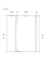
- FIG. 1 is an enlarged plan view of a main part showing an enlarged main part of the back surface of a solar cell string applied to a solar cell module according to an embodiment of the present invention
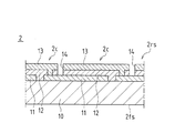
- FIG. 2 is an arrow BB in FIG. FIG.
- the solar cell string 2 has a configuration in which a plurality of solar cells 2c are arranged in a row and connected in series to a light-receiving surface glass 10 that is a translucent insulating substrate.
- the light-receiving surface glass 10 constitutes the surface 2fs of the solar cell string 2, and allows the sunlight irradiated to the light-receiving surface glass 10 to enter the solar cells 2c.
- a plurality of back surface electrodes 13 of the solar cells 2c are arranged in a row on the back surface 2rs of the solar cell string 2.
- the solar battery cell 2 c includes a surface electrode 11 formed on the light-receiving surface glass 10, a semiconductor layer 12 stacked on the surface electrode 11, and a back electrode 13 stacked on the semiconductor layer 12.
- the front electrode 11 is connected to the back electrode 13 of the adjacent solar battery cell 2c. That is, the solar cells 2 c are connected in series over the entire solar cell string 2.
- the surface electrode 11 is a transparent electrode and is made of a metal oxide such as SnO2, ITO, ZnO, for example.
- the metal oxide can be formed by, for example, a CVD method or a sputtering method.
- Each surface electrode 11 is separately formed by patterning that irradiates a metal oxide formed on the surface of the light-receiving surface glass 10 with laser light.
- Each surface electrode 11 is made to respond
- a semiconductor layer 12 (for example, a silicone-based amorphous film or a microcrystalline film can be applied) is formed by a CVD method or the like.
- Each semiconductor layer 12 is separately formed by patterning that irradiates the semiconductor layer 12 formed on the surface of the surface electrode 11 with laser light.
- Each semiconductor layer 12 is made to correspond to the solar battery cell 2c.
- Laser light that is not absorbed by the light-receiving surface glass 10 and the surface electrode 11 but is absorbed only by the semiconductor layer 12, for example, a second harmonic of an Nd: YAG laser having a wavelength of 532 nm can be used.
- the back electrode 13 (for example, a metal film such as Ag or Al, or a laminate of a metal film and a metal oxide can be used) is formed by sputtering or electron beam evaporation. Film.
- Each back electrode 13 is separated and formed by a separation groove 14 formed by patterning that irradiates a laser beam together with the semiconductor layer 12. That is, the back electrode 13 and the semiconductor layer 12 corresponding to the solar battery cell 2 c are formed by the separation groove 14.
- a solar cell string (thin film solar cell string) 2 in which a plurality of solar cells 2c (thin film solar cells) are connected in series is manufactured by film formation and laser patterning of the front electrode 11, the semiconductor layer 12, and the back electrode 13.
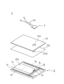
- FIG. 3 is an exploded perspective view showing the components of the solar cell module according to the embodiment of the present invention in an exploded manner
- FIG. 4 is a partially enlarged sectional view of the solar cell module according to the embodiment of the present invention. is there.
- the solar cell module 1 includes a solar cell string (solar cell element) 2, the surface electrode 11 of the solar cell 2 c at one end of the solar cell string 2, and the solar cell 2 c at the other end.
- the terminal electrode 15 formed on the back electrode 13, the bus bar lead 16, and the output lead wire 20 are provided. That is, the terminal electrode 15 is disposed on both ends of the back surface 2 rs of the solar cell string 2, and the bus bar lead 16 disposed on the terminal electrode 15 is connected to the terminal electrode 15.
- the bus bar lead 16 is formed of, for example, a copper wire plated with solder.
- an output lead wire 20 for taking out the electric power generated in the solar cell string 2 to the outside is connected to the bus bar lead 16 by, for example, soldering.
- the output lead wire 20 is composed of a bare conductor (for example, copper wire), and is disposed on the back surface 2rs via the insulating resin film formation layer 21 formed on the back surface 2rs. It extends toward the center of the solar cell string 2 in the intersecting direction.
- a bare conductor for example, copper wire
- the output lead wire 20 is a bare conductor, but a coated conductor covered with an insulating member such as PET (polyethylene terephthalate) may be used.
- the insulating resin film-forming layer 21 can be omitted.
- the bus bar leads 16, and the output lead wires 20 provided on the back surface 2 rs of the solar cell string 2 The filling member sheet 22s and the back glass 24 are laminated.
- the filling member sheet 22s is filled between the insulating resin film-forming layer 21 and the output lead wire 20 by a heat and pressure treatment (for example, vacuum laminating treatment) applied to the filling member sheet 22s and the back glass 24.
- the filled filling member layer 22 (see FIG. 4) is formed.
- An EVA (ethylene vinyl acetate) sheet can be applied as the filling member sheet 22s.
- the back glass 24 is in close contact with the filling member layer 22 to cover the output lead wire 20 with the filling member layer 22. Therefore, since the filling member layer 22 can be reliably formed, it is possible to reliably insulate and protect the output lead wire 20 with respect to the back electrode 13, and the solar cell module 1 that is easy, highly accurate and highly reliable can be obtained. Can be formed.
- Each of the filling member sheet 22s and the back glass 24 has an opening for drawing out the tip of the output lead wire 20 (a lead drawing opening 22sh in the case of the filling member sheet 22s, and a lead drawing opening 24h in the case of the back glass 24. )have. That is, the output lead wire 20 is bent at the lead-out position and pulled out through the lead lead-out openings 22sh and 24h.
- the lead lead opening 22sh formed in the filling member sheet 22s is two openings that are formed slightly larger according to the cross-sectional shape of each output lead wire 20.
- the lead lead opening 24 h provided in the back glass 24 is one large round hole opening so that both output lead wires 20 can be enclosed.
- the output lead wire 20 drawn out from the lead drawing opening 22 sh of the back glass 24 is connected in the terminal box 3 that is bonded and fixed to the back glass 24, and externally through the power take-out cable 45 that is also connected in the terminal box 3. The power is taken out.
- the solar cell module 1 is a laminated glass thin film solar cell module and has a frameless structure. .
- FIG. 5 is a perspective view of the terminal box according to the present embodiment
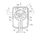
- FIG. 6 is a plan view of the terminal box with the lid body removed
- FIG. 7 is a bottom view of the terminal box
- FIG. 9 is a partially enlarged end view of a state in which the terminal box corresponding to the CC line portion is attached to the back glass
- FIG. 9 is a diagram of a state in which the terminal box corresponding to the DD line portion of FIG. FIG.
- FIGS. 8 and 9 show a state before the filling material 39 is filled.
- the terminal box 3 includes a protective case 31 formed in a flat rectangular box shape and a lid 32 that covers the upper surface opening of the protective case 31.
- a protective case 31 formed in a flat rectangular box shape and a lid 32 that covers the upper surface opening of the protective case 31.
- two lead wire openings 33 a for introducing each output lead wire 20 drawn out from the opening 24 h of the back glass 24 of the solar cell module 1 and the inside of the opening 24 h of the back glass 24 are provided.
- a filler opening 33b which is a relatively large opening for filling a filler 39, which will be described later, and one or a plurality (for removing air in the opening 24h of the back glass 24 when the filler 39 is filled)
- three) deaeration ports 33c are provided. *
- the deaeration port 33c is provided so that either one or both of the terminal block 34 and the lead wire opening 33a are located between the deaeration port 33c and the filler opening 33b. good.
- the deaeration port 33c is preferably provided at the peripheral edge of the opening 24h of the back glass 24.
- the shape of the opening 33b for the filler is not particularly limited, but the position of the terminal block 34, the position of the lead wire opening 33a, the arrangement position after the connection of the power extraction cable 45, and the like are taken into consideration. Thus, it is preferable to avoid these regions.
- the filler opening 33b may have a larger opening than the lead wire opening 33a and the deaeration port 33c.
- a terminal block 34 is provided beside the lead wire opening 33a, and the output lead wire 20 introduced inside is fixed to the terminal block 34.
- the lead wire opening 33a and the filler opening 33b are individually provided on the bottom wall 33 of the protective case 31, when the filler 39 is filled into the opening 24h of the back glass 24, the lead The filler 39 can be reliably filled into the opening 24h of the back glass 24 without passing through the line opening 33a. Further, since the deaeration port 33c is provided in the bottom wall 33 of the protective case 31, the air pushed out from the opening 24h by the filler 39 filled in the opening 24h passes through the deaeration port 33c to the outside. Therefore, the filler 39 is tightly filled in the opening 24h. That is, the structure prevents the generation of bubbles.
- the lead wire opening 33a is formed in a tapered shape that gradually decreases in diameter from the bottom surface (surface contacting the back glass 34) 35a side of the protective case 31 toward the box inner surface 35b side.
- the opening shape of the lead wire opening 33 a on the box inner surface 35 b side is slightly larger than the cross-sectional shape of the output lead wire 20.
- the filling material filled in the opening 24 h of the back glass 24 is made by making the opening shape of the lead wire opening 33 a on the box inner surface 35 b side slightly larger than the cross-sectional shape of the output lead wire 20. 39 can be prevented from flowing back into the protective case 31 through the lead wire opening 33a.
- the lead wire opening 33 a has a structure that hardly passes the filler 39. Further, with such a taper shape, when the output lead wire 20 is passed through the lead wire opening 33a, the taper surface serves as a guide surface for the output lead wire 20, so that the output lead wire 20 is opened to the lead wire. It can be easily inserted into the portion 33a. Further, if the opening shape of the lead wire opening 33a on the box inner surface 35b side is set to be slightly larger than the cross-sectional shape of the output lead wire 20, the output lead wire 20 can be output only by being inserted into the lead wire opening portion 33a. The lead-out position of the lead wire 20, that is, the attachment position of the terminal box 3 can be easily determined.
- the bottom surface 35a of the bottom wall 33 of the protective case 31 includes all of the lead wire opening 33a, the filler opening 33b, and the deaeration port 33c, and the opening of the back glass 24 of the solar cell module 1.
- a ring-shaped groove 37 is formed along the periphery of the portion 24h.
- the groove 37 is formed so that an adhesive (for example, silicone resin) 40 applied to the bottom surface 35a of the protective case 31 is bonded to the back glass 24 in order to bond the terminal box 3 to the back glass 24. Protruding into the opening 24h can also be prevented.
- an adhesive for example, silicone resin
- a ring-shaped groove 38 is formed on the bottom surface 35a of the bottom wall 33 of the protective case 31 along the outer peripheral edge of the bottom surface 35a.
- the portion where the grooves 37 and 38 are provided has a rib shape that protrudes toward the bottom surface 35 a of the protective case 31, but the grooves 37 and 38 are provided directly on the bottom surface 35 a of the protective case 31. It is good also as the structure comprised.
- two insertion holes 36 into which power extraction cables 45 for supplying electric power to the outside can be respectively inserted are provided on one side wall of the protective case 31, and each power extraction cable 45 inserted through the insertion hole 36 is provided. Is fixed to the terminal block 34.
- the fixing to the terminal block 34 has, for example, a screw structure.
- a bypass diode serving as a circuit for avoiding damage to the solar cell module is connected between the plus side and minus side terminal blocks 34.
- FIGS. 10 to 12 show the respective steps of the attachment procedure, and are partially enlarged end views showing a state in which the terminal box corresponding to the DD line portion of FIG. 6 is attached to the back glass.
- FIG. 10 to FIG. 12 are illustrated with the light receiving surface side facing down and the back surface side facing up, according to the actual manufacturing process.
- the lid 32 of the terminal box 3 is in an open state. That is, only the protective case 31 is attached.
- an adhesive 40 such as a silicone resin is applied to the bottom surface 35a of the bottom wall 33 of the protective case 31, and the output lead wire 20 is inserted into the lead wire opening 33a so that the lead wire 20 is pulled out, that is, protected.
- the bottom surface 35 a of the protective case 31 is attached to the surface of the back glass 24 via the adhesive 40. This state is shown in FIGS.
- the adhesive 40 even if the adhesive 40 is pushed and spreads slightly in the lateral direction, the adhesive 40 that is about to protrude from the bottom surface 35a is in the groove 37 inside the bottom surface and / or the groove 38 outside the bottom surface. It collects inside and hardly protrudes beyond that.
- the filler nozzle 51 is disposed above the filler opening 33b, and a filler (for example, two-pack curable silicone) 39 is applied to the opening 24h of the back glass 24 through the filler opening 33b to some extent. Drip from height. Thereby, the opening 24 h of the back glass 24 is filled with the filler 39. At this time, there is a possibility that some bubbles may remain in the corner between the filler 39 filled up to just before overflowing from the filler opening 33b and the bottom surface 35a of the protective case 31. In this embodiment, air pushed out from the inside of the opening 24h by the filler 39 filled in the opening 24h and the remaining bubbles pass outside through the deaeration port 33c, so as shown in FIG. The material 39 is densely filled in the opening 24h.
- a filler for example, two-pack curable silicone
- filler 39 is subsequently dropped. As a result, the filler 39 overflows into the protective case 31 and finally fills the protective case 31 with the filler 39 as shown in FIG.
- the filling material 39 filled in the opening 24h and the filling material filled in the protective case 31 are made of the same material, so that the filling operation can be performed in series (that is, the operation) In addition to the reduction in the number of terms, the attachment strength between the back glass 24 after filling and the protective case 31 can be improved.
- the attachment of the terminal box 3 to the solar cell module 1 is completed by attaching the lid 32 to the protective case 31.
- the filling material 39 filled in the opening 24h and the filling material filled in the protective case 31 are made of the same material. However, if they are not the same material, these filling materials Is a filler that adheres to each other at the joint surface.
- a highly reliable solar cell module can be realized, and is widely applied to fields using solar cells, such as a solar power generation system, and is beneficial.
Landscapes
- Photovoltaic Devices (AREA)
Abstract
本発明の太陽電池モジュールは、受光面ガラスと裏面ガラスとの間に太陽電池素子が介在し、前記裏面ガラスに前記太陽電池素子の出力リード線を外部に引き出す開口部が設けられ、前記裏面ガラスの前記開口部を覆うようにして、端子ボックスが接着固定された合わせガラス構造の太陽電池モジュールであって、前記端子ボックスは、前記裏面ガラスに接着固定される底壁に、前記出力リード線を通す第1の開口部と、裏面側からの平面視において前記裏面ガラスの前記開口部と重なるように配置された、前記第1の開口部とは別の第2の開口部を有し、前記裏面ガラスの前記開口部、前記第2の開口部及び前記端子ボックスには、充填材が充填されている。
Description
本発明は、太陽電池素子を受光面ガラスと裏面ガラスとの間に介在させた合わせガラス構造の太陽電池モジュール、特にフレームレス構造の太陽電池モジュールに係り、より詳細には、端子ボックスの取り付け構造に関する。
近年、重量軽減のため、モジュールの周囲を保持するフレームを無くしたフレームレス構造の太陽電池モジュールが提供されており、太陽電池素子を受光面ガラスと裏面ガラスとの間に介在させた合わせガラス構造の太陽電池モジュールにおいても、フレームレス構造のものが提供されている。
このような合わせガラス構造の太陽電池モジュールでは、裏面ガラスに太陽電池素子から電力を取り出すための出力リード線を引き出す開口部が形成され、この開口部を覆うようにして、出力リード線を結線する端子ボックスが裏面ガラスに接着材により接着固定されている。
このような端子ボックスの取り付け構造に関しては、例えば特許文献1に記載されている。
特許文献1に記載の太陽電池用端子ボックスは、図13に示すように、端子ボックス123の底面に予め接着剤ポリマーエース-A(HM-50)134-Aを貼付けている。この接着剤134-Aには開口穴126部分が確保され、かつ、端子ボックス123の開口部126と同じ寸法に打ち抜き加工されている。同じタイプで同じ寸法及び同じ開口穴126を有する接着剤134-Bを太陽電池モジュール130の金属鋼板(裏面ガラスに相当)120の所定位置に貼付け固定する。この状態で、接着剤134-Aが貼付けられた端子ボックス123を接着剤134-Bの位置に両者の開口穴126部分を合わせて貼り合せる。接着してから2時間経過後、端子ボックス123内に2液型シリコーン樹脂材料(以下、充填材という。)を混合充填し、硬化させて水分浸入防止を兼ねた絶縁処理を行い、端子ボックス蓋123cを取り付けるようになっている。なお、図中の符号110は薄膜太陽電池素子、114は裏面保護層、111,118は接着層、121は主配線、122は補助配線、124は出力リード線、123aは端子台、123bは端子ネジ、125は出力ケーブルである。
このような端子ボックス123の取り付け方法及び取り付け構造では、金属鋼板120の開口穴126に充填材が十分に満たされない可能性がある。
すなわち、開口穴126は、薄膜太陽電池素子110から電力を取り出すための出力リード線124を引き出して端子ボックス123内に引き込むための開口穴であり、この開口穴126から充填材を充填した場合、充填材が出力リード線124の裏側に回り込まずに気泡ができる可能性がある。
本発明はかかる問題点を解決すべく創案されたもので、その目的は、充填材に気泡ができ難く、信頼性が向上した太陽電池モジュール及び太陽電池モジュールの製造方法並びにこの太陽電池モジュールの製造に用いられる端子ボックスを提供することにある。
上記課題を解決するため、本発明の太陽電池モジュールは、受光面ガラスと裏面ガラスとの間に太陽電池素子が介在し、前記裏面ガラスに前記太陽電池素子の出力リード線を外部に引き出す開口部が設けられ、前記裏面ガラスの前記開口部を覆うようにして、端子ボックスが接着固定された合わせガラス構造の太陽電池モジュールであって、前記端子ボックスは、前記裏面ガラスに接着固定される底壁に、前記出力リード線を通す第1の開口部と、裏面側からの平面視において前記裏面ガラスの前記開口部と重なるように配置された、前記第1の開口部とは別の第2の開口部を有し、前記裏面ガラスの前記開口部、前記第2の開口部及び前記端子ボックスには、充填材が充填されていることによって特徴付けられている。
このような特徴を有する本発明によれば、端子ボックスの底壁に、第1の開口部に加え、第2の開口部を別に設けることで、充填材を裏面ガラスの開口部内に充填する際、空気の排出が良くなり、気泡が発生し難くなるため、防湿性などの信頼性が向上する。
上記構成において、本発明の太陽電池モジュールは、前記開口部及び前記第2の開口部に充填される充填材と前記端子ボックスに充填される充填材とが同一の材料であることが好ましい。
この構成では、充填作業を一連に行うことができるとともに、充填後の裏面ガラスと端子ボックスとの取り付け強度を向上させることができる。
さらに、本発明の太陽電池モジュールは、前記第2の開口部は複数個設けられていてもよい。
本発明の太陽電池モジュールの製造方法は、受光面ガラスと裏面ガラスとの間に太陽電池素子を介在させた状態で、前記受光面ガラスと前記裏面ガラスとを接着する工程と、前記裏面ガラスに設けられた開口部を通して前記太陽電池素子の出力リード線を外部に引き出す工程と、前記裏面ガラスの前記開口部を覆うように、端子ボックスを接着固定する工程と、前記裏面ガラスに接着固定される前記端子ボックスの底壁に設けられた第1の開口部に、前記出力リード線を通す工程と、前記端子ボックスの前記底壁に設けられた、前記第1の開口部とは別の第2の開口部を介して前記裏面ガラスの前記開口部内に充填材を充填する工程と、前記端子ボックス内に充填材を充填する工程とを含むことによって特徴付けられている。
また、本発明の端子ボックスは、出力リード線を外部に引き出す開口部が、太陽電池モジュールの裏面ガラスに形成されており、前記開口部を塞いだ状態で前記裏面ガラスに接着固定される端子ボックスであって、当該端子ボックスの底壁には、前記出力リード線を通すリード線開口部と、前記裏面ガラスの前記開口部内に充填材を充填するための充填材用開口部とが設けられていることによって特徴付けられている。
このような特徴を有する本発明によれば、端子ボックスの底壁に、リード線開口部と充填材用開口部とを個別に設けることで、充填材を裏面ガラスの開口部内に充填する際、リード線開口部を通ることなく、充填材を裏面ガラスの開口部内に充填することができる。
本発明の端子ボックスは、上記構成において、前記リード線開口部は、充填材を通さない構造とされていてもよい。
リード線開口部をこのような構造とすることで、裏面ガラスの開口部内に充填された充填材が満杯状態となっても、充填材がリード線開口部を通って端子ボックス内に逆流するのを防止することができる。
具体的には、前記リード線開口部を、前記底壁の底面からボックス内面に向かって漸次縮径するテーパ状に形成する構造としてもよい。
このような構造とすることにより、ボックス内面側のリード線開口部と出力リード線との隙間を狭くすることができるため、裏面ガラスの開口部内に充填された充填材が満杯状態となっても、充填材がリード線開口部を通って端子ボックス内に逆流することはほとんどない。また、このような構造により、出力リード線をリード線開口部に通すときには、このテーパ面が出力リード線のガイド面となり、出力リード線をリード線開口部に容易に挿通することができる。さらに、ボックス内面側のリード線開口部の開口形状を、出力リード線の横断面形状より少し大きな形状としておけば、出力リード線をリード線開口部に挿通するだけで、出力リード線の引き出し位置、すなわち、端子ボックスの取り付け位置を容易に決めることができる。
また、本発明の端子ボックスによれば、前記底壁の底面に、前記裏面ガラスの前記開口部の周囲に沿うように溝が形成された構成としてもよい。
端子ボックスの底壁の底面に、裏面ガラスの開口部の周囲に沿うように溝を設けることで、裏面ガラスの開口部に充填された充填材のうち不要な充填材がこの溝に溜まるため、端子ボックスの底面への充填材のはみ出しを防止することができる。すなわち、充填材が少し多く充填されたとしても、不要分はこの溝に溜まるので、端子ボックスの底面側への漏洩を防止することができる。また、この溝は、端子ボックスを裏面ガラスに接着するために、端子ボックスの底面に塗布された接着材(例えば、シリコーン樹脂等)が、接着の際に裏面ガラスの開口部内にはみ出すことも防止することができる。
さらにまた、本発明の端子ボックスによれば、前記底壁の底面には、前記底面の外周縁に沿って溝が形成された構成としてもよい。
端子ボックスの底壁の外周縁にも溝を形成することで、端子ボックスの底面に塗布された接着材が端子ボックスの底面から外側にはみ出ることを防止することができる。
また、本発明の端子ボックスによれば、前記溝を複数条に形成してもよい。このように溝を複数条に形成することで、充填材や接着材のはみ出しをより確実に防止することができる。
また、本発明の端子ボックスによれば、前記底壁に、前記充填材の充填時に前記裏面ガラスの前記開口部内の空気を抜くための脱気口が1または複数個設けられた構成としてもよい。
このような脱気口を設けることにより、裏面ガラスの開口部内に充填材を充填する際、開口部内に充填された充填材によって押し出された空気が脱気口を通って抜けるため、充填材が開口部内に密に充填され、空気溜まりの発生を防止することができる。
本発明によれば、端子ボックスの底壁に、第1の開口部に加え、第2の開口部を別に設けることで、充填材を裏面ガラスの開口部内に充填する際、空気の排出が良くなり、気泡が発生し難くなるため、防湿性などの信頼性が向上する。
以下、本発明の実施の形態について、図面を参照して説明する。
図1は、本発明の実施の形態に係る太陽電池モジュールに適用される太陽電池ストリングの裏面要部を拡大して示す要部拡大平面図、図2は、図1の矢符B-Bから見た断面図である。
太陽電池ストリング2は、透光性絶縁基板である受光面ガラス10に太陽電池セル2cが列状に複数配置され直列接続された形態とされている。受光面ガラス10は、太陽電池ストリング2の表面2fsを構成し、受光面ガラス10へ照射された太陽光を太陽電池セル2cへ入射させる。太陽電池ストリング2の裏面2rsには、太陽電池セル2cの裏面電極13が列状に複数配置されている。
太陽電池セル2cは、受光面ガラス10に形成された表面電極11、表面電極11に積層された半導体層12、半導体層12に積層された裏面電極13を備えている。表面電極11は、隣接する太陽電池セル2cの裏面電極13に接続されている。つまり、太陽電池セル2cは、太陽電池ストリング2の全体にわたって直列接続されている。
表面電極11は、透明電極であり、例えばSnO2、ITO、ZnOなどの金属酸化物で構成される。金属酸化物は、例えばCVD法やスパッタ法などにより成膜することが可能である。それぞれの表面電極11は、受光面ガラス10の表面に成膜した金属酸化物をレーザ光を照射するパターニングによって分離形成される。それぞれの表面電極11は、太陽電池セル2cに対応させてある。レーザ光は、受光面ガラス10では吸収されず透明電極(表面電極11)だけで吸収されるもの、例えば、波長1.06μmのNd:YAGレーザの基本波を使用することができる。
次に、半導体層12(例えば、シリコーン系の非晶質膜や微結晶膜を適用することが可能である。)をCVD法などにより成膜する。それぞれの半導体層12は、表面電極11の表面に成膜した半導体層12をレーザ光を照射するパターニングによって分離形成される。それぞれの半導体層12は、太陽電池セル2cに対応させてある。レーザ光は、受光面ガラス10及び表面電極11では吸収されず半導体層12だけで吸収されるもの、例えば、波長532nmのNd:YAGレーザの第2次高調波を使用することができる。
次に、裏面電極13(例えば、Ag,Alなどの金属膜や、金属膜と金属酸化物とを積層したものを適用することが可能である。)をスパッタ法や電子ビーム蒸着法などにより成膜する。それぞれの裏面電極13は、半導体層12とともにレーザ光を照射するパターニングによって形成された分離溝14によって分離形成される。つまり、分離溝14によって、太陽電池セル2cに対応させた裏面電極13、半導体層12を形成する。レーザ光は、受光面ガラス10及び表面電極11では吸収されず半導体層12及び裏面電極13で吸収されるもの、例えば、波長532nmのNd:YAGレーザの第2次高調波を使用することができる。
表面電極11、半導体層12、裏面電極13を加工形成するレーザ光は、いずれも受光面ガラス10の方向から照射される。表面電極11、半導体層12、裏面電極13の成膜及びレーザパターニングにより、複数の太陽電池セル2c(薄膜太陽電池セル)が互いに直列接続された太陽電池ストリング(薄膜太陽電池ストリング)2が作製される。
図3は、本発明の実施の形態に係る太陽電池モジュールの各構成部材を分解して示す分解斜視図、図4は、本発明の実施の形態に係る太陽電池モジュールの一部拡大断面図である。
本実施の形態に係る太陽電池モジュール1は、太陽電池ストリング(太陽電池素子)2と、太陽電池ストリング2の一端部の太陽電池セル2cの表面電極11上、及び他端部の太陽電池セル2cの裏面電極13上に形成された端子電極15と、バスバーリード16と、出力リード線20とを備えている。つまり、太陽電池ストリング2の裏面2rsの両端には端子電極15が配置され、端子電極15には端子電極15に重ねて配置されたバスバーリード16が接続されている。なお、バスバーリード16は、例えば半田めっきされた銅線で形成されている。
また、バスバーリード16には太陽電池ストリング2で発生した電力を外部に取り出すための出力リード線20が例えば半田付けによって接続されている。
本実施の形態では、出力リード線20は、裸導線(例えば銅線)で構成してあり、裏面2rsに形成された絶縁樹脂成膜層21を介して裏面2rsに配置され、端子電極15と交差する方向で太陽電池ストリング2の中心側に向けて延長されている。
本実施の形態では、出力リード線20は裸導線としているが、PET(ポリエチレンテレフタレート)のような絶縁部材によって被覆された被覆導線を用いてもよい。この場合には、絶縁樹脂成膜層21を省略することができる。
太陽電池ストリング2の裏面2rsに絶縁樹脂成膜層21、バスバーリード16、出力リード線20を設けた状態で、太陽電池ストリング2の裏面2rsを封止するために、裏面2rsに対応させて、充填部材シート22s及び裏面ガラス24が積層される。充填部材シート22sは、充填部材シート22s及び裏面ガラス24に対して施される加熱加圧処理(例えば、真空ラミネート処理。)によって、絶縁樹脂成膜層21と出力リード線20との間に充填された充填部材層22(図4参照)を形成する。なお、充填部材シート22sとしては、EVA(エチレンビニルアセテート)シートを適用することが可能である。
つまり、裏面ガラス24は、充填部材層22に密着して出力リード線20を充填部材層22によって被覆させる。したがって、充填部材層22を確実に形成できることから、出力リード線20を裏面電極13に対して確実に絶縁して保護することが可能となり、容易かつ高精度に信頼性の高い太陽電池モジュール1を形成することができる。
充填部材シート22s及び裏面ガラス24は、いずれも出力リード線20の先端を引き出すための開口部(充填部材シート22sの場合はリード引き出し開口部22sh、裏面ガラス24の場合はリード引き出し開口部24h。)を有している。つまり、出力リード線20は、引き出し位置で折り曲げられ、各リード引き出し開口部22sh,24hを通って外部へ引き出される。
ここで、本実施の形態では、充填部材シート22sに形成されるリード引き出し開口部22shは、各出力リード線20の横断面形状に合わせて若干大きめに形成された2つの開口部となっているが、裏面ガラス24に設けられているリード引き出し開口部24hは、両出力リード線20を内包できるように1つの大きな丸穴形状の開口部となっている。
裏面ガラス24のリード引き出し開口部22shから引き出された出力リード線20は、裏面ガラス24に接着固定される端子ボックス3内で接続され、同じく端子ボックス3内で接続された電力取り出しケーブル45を通じて外部に電力を取り出すようになっている。
本実施の形態では、太陽電池ストリング2を合わせガラス構造の薄膜太陽電池ストリングとしていることから、太陽電池モジュール1は、合わせガラス構造の薄膜太陽電池モジュールであり、かつ、フレームレス構造となっている。
次に、上記構成の太陽電池モジュール1に取り付けられる端子ボックス3の構造について具体的に説明する。
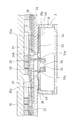
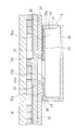
図5は、本実施の形態に係る端子ボックスの斜視図、図6は、端子ボックスの蓋体を取り外した状態の平面図、図7は、端子ボックスの底面図、図8は、図6のC-C線部分に対応した端子ボックスを裏面ガラスに取り付けた状態の一部拡大端面図、図9は、図6のD-D線部分に対応した端子ボックスを裏面ガラスに取り付けた状態の一部拡大端面図である。ただし、図8及び図9は、充填材39を充填する前の状態を示している。
本実施の形態の端子ボックス3は、偏平な方形の箱形状に形成された保護ケース31と、この保護ケース31の上面開口部を覆う蓋体32とから構成されており、保護ケース31の底壁33には、太陽電池モジュール1の裏面ガラス24の開口部24hから引き出された各出力リード線20を内部に導入するための2つのリード線開口部33aと、裏面ガラス24の開口部24h内に後述する充填材39を充填するための比較的大きな開口である充填材用開口部33bと、充填材39の充填時に裏面ガラス24の開口部24h内の空気を抜くための1または複数個(この例では3個)の脱気口33cとが設けられている。
なお、脱気口33cは、端子台34、リード線開口部33aのいずれか一方、または両方が、脱気口33cと充填材用開口部33bとの間に位置するように設けておくのが良い。また、脱気口33cは、裏面ガラス24の開口部24hの周縁部に、設けておくのが良い。また、充填材用開口部33bは、その形状が特に限定されるものではないが、端子台34の位置やリード線開口部33aの位置、及び電力取り出しケーブル45の接続後の配置位置等を考慮して、これらの領域を避けて形成するのが良い。充填材用開口部33bは、リード線開口部33a及び脱気口33cより大きな開口を有すると良い。
また、リード線開口部33aの横には端子台34が設けられており、内部に導入された出力リード線20は、この端子台34に固定されている。
このように、保護ケース31の底壁33にリード線開口部33aと充填材用開口部33bとを個別に設けることで、充填材39を裏面ガラス24の開口部24h内に充填する際、リード線開口部33aを通すことなく、充填材39を裏面ガラス24の開口部24h内に確実に充填することができる。また、保護ケース31の底壁33に脱気口33cを設けているので、開口部24h内に充填された充填材39によって開口部24h内から押し出された空気が脱気口33cを通って外部に抜けるため、充填材39が開口部24h内に密に充填される。すなわち、気泡の発生を防止する構造となっている。
リード線開口部33aは、図8に示すように、保護ケース31の底壁33の底面(裏面ガラス34に接触する面)35a側からボックス内面35b側に向かって漸次縮径するテーパ状に形成されており、ボックス内面35b側のリード線開口部33aの開口形状は、出力リード線20の横断面形状より少し大きな形状となっている。このように、ボックス内面35b側のリード線開口部33aの開口形状を、出力リード線20の横断面形状より少し大きな形状とすることで、裏面ガラス24の開口部24h内に充填された充填材39が、リード線開口部33aを通って保護ケース31内に逆流するのを防止することができる。すなわち、リード線開口部33aは、充填材39をほとんど通さない構造となっている。また、このようなテーパ状とすることで、出力リード線20をリード線開口部33aに通すときには、このテーパ面が出力リード線20のガイド面となることから、出力リード線20をリード線開口部33aに容易に挿通することができる。さらに、ボックス内面35b側のリード線開口部33aの開口形状を、出力リード線20の横断面形状より少し大きな形状としておけば、出力リード線20をリード線開口部33aに挿通するだけで、出力リード線20の引き出し位置、すなわち、端子ボックス3の取り付け位置を容易に決定することができる。
また、保護ケース31の底壁33の底面35aには、リード線開口部33aと充填材用開口部33bと脱気口33cの全てを内包し、かつ、太陽電池モジュール1の裏面ガラス24の開口部24hの周囲に沿うようにリング状の溝37が形成されている。このような溝37を設けることで、裏面ガラス24の開口部24hに充填された充填材39のうち不要な充填材がこの溝37内に溜まるため、保護ケース31の底面35aへの充填材39のはみ出し(すなわち、保護ケース31の底面35aへの充填材39の付着)を防止することができる。また、この溝37は、端子ボックス3を裏面ガラス24に接着するために、保護ケース31の底面35aに塗布された接着材(例えば、シリコーン樹脂等)40が、接着の際に裏面ガラス24の開口部24h内にはみ出すことも防止することができる。
また、保護ケース31の底壁33の底面35aには、底面35aの外周縁に沿ってリング状の溝38が形成されている。このように、保護ケース31の底面35aの外周縁にも溝38を形成することで、保護ケース31の底面35aに塗布された接着材40によって保護ケース31を裏面ガラス4に接着する際、押し延ばされた接着材40が保護ケース31の底面35aから外側にはみ出る前に、この溝38内に溜まるため、接着材40の外側へのはみ出しを事前に防止することができる。
なお、本実施の形態では、上記各溝37,38を1条のみ形成しているが、それぞれ同心状に複数条形成してもよい。溝37,38を複数条形成することで、充填材39や接着材40のはみ出しをより確実に防止することができる。また、本実施の形態では、各溝37,38を設ける部分を保護ケース31の底面35a側に突出させたリブ形状としているが、各溝37,38は、保護ケース31の底面35aに直接設けられた構成としても良い。
また、保護ケース31の一側壁には、外部に電力を供給する電力取り出しケーブル45をそれぞれ挿入可能な2つの挿入穴36が設けられており、この挿入穴36を通じて挿入された各電力取り出しケーブル45の先端部が端子台34に固定される。端子台34への固定は、例えばネジ止め構造となっている。なお、プラス側とマイナス側の端子台34の間には、図示は省略しているが、太陽電池モジュールの破損に対する回避回路の役割を果たすバイパスダイオードが接続されている。
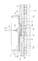
次に、上記構成の端子ボックス3を太陽電池モジュール1(太陽電池ストリング2)の裏面ガラス24に取り付ける手順について、図8ないし図12を参照して説明する。なお、図10ないし図12は、取り付け手順の各工程を示しており、図6のD-D線部分に対応した端子ボックスを裏面ガラスに取り付けた状態の一部拡大端面図である。ただし、図10ないし図12は、実際の製造工程に従って、受光面側を下、裏面側を上にして図示している。また、端子ボックス3の蓋体32は開いた状態となっている。つまり、保護ケース31のみ取り付けた状態となっている。
まず、保護ケース31の底壁33の底面35aに、例えばシリコーン樹脂等の接着材40を塗布し、出力リード線20をリード線開口部33aに挿通してリード線20の引き出し位置、すなわち、保護ケース31の取り付け位置を決めた後、保護ケース31の底面35aを接着材40を介して裏面ガラス24の表面に貼り付ける。この状態が図8及び図9である。このとき、接着材40が押し延ばされて横方向に多少広がったとしても、底面35aからはみ出だそうとする接着材40は、底面内側の溝37内、及び/または、底面外側の溝38内に溜まり、それ以上はみ出すことはほとんどない。
この状態で、図示は省略しているが、端子台34に出力リード線20の先端部と電力取り出しケーブル45の先端部とを電気的に固定した後、図10に示すように、保護ケース31の充填材用開口部33bの上方に充填用ノズル51を配置し、充填材用開口部33bを通じて、裏面ガラス24の開口部24hに充填材(例えば、2液硬化型シリコーン等)39をある程度の高さから滴下する。これにより、裏面ガラス24の開口部24hが充填材39により充填されていく。このとき、充填材用開口部33bから溢れ出る寸前まで充填された充填材39と保護ケース31の底面35aとの間には、隅の方に若干の気泡が残る可能性があるが、本実施の形態では、開口部24h内に充填された充填材39によって開口部24h内から押し出された空気及び残った気泡が脱気口33cを通って外部に抜けるため、図11に示すように、充填材39が開口部24h内に密に充填されることになる。
この後、充填用ノズル51を上方に引き上げつつ(若しくは、最初から図12に示す所定の高さ位置に配置しておいてもよい。)、引き続いて充填材39を滴下する。これにより、充填材39が保護ケース31内に溢れてきて、最終的には図12に示すように、保護ケース31内を充填材39で一杯まで充填する。
このように、開口部24h内に充填される充填材39と、保護ケース31内に充填される充填材とを同一の材料とすることで、充填作業を一連に行うことができる(すなわち、作業項数の削減)とともに、充填後の裏面ガラス24と保護ケース31との取り付け強度を向上させることができる。
この後、図示は省略しているが、保護ケース31に蓋体32を取り付けることで、太陽電池モジュール1への端子ボックス3の取り付けを完了する。
なお、本実施形態では、開口部24h内に充填される充填材39と、保護ケース31内に充填される充填材とを同一の材料としたが、同一の材料ではない場合、これらの充填材は互いの接合面で接着する充填材とされる。
なお、今回開示した実施の形態はすべての点で例示であって、限定的な解釈の根拠となるものではない。従って、本発明の技術的範囲は、上記した実施形態のみによって解釈されるものではなく、特許請求の範囲の記載に基づいて画定される。また、特許請求の範囲と均等の意味及び範囲内でのすべての変更が含まれる。
本発明により、信頼性の高い太陽電池モジュールを実現することができ、太陽発電システムなど、太陽電池を用いた分野に幅広く適用され、有益である。
1 太陽電池モジュール
2 太陽電池ストリング(太陽電池素子)
2c 太陽電池セル
2fs 表面
2rs 裏面
3 端子ボックス
10 受光面ガラス
11 表面電極
12 半導体層
13 裏面電極
14 分離溝
15 端子電極
16 バスバーリード
20 出力リード線
21 絶縁樹脂成膜層
22 充填部材層
22s 充填部材シート
22sh リード引き出し開口部
24 裏面ガラス
24h リード引き出し開口部(開口部)
31 保護ケース
32 蓋体
33 底壁
33a リード線開口部
33b 充填材用開口部
33c 脱気口
34 端子台
35a 底面
35b ボックス内面
36 挿入穴
37,38 溝
39 充填材
40 接着材
45 電力取り出しケーブル
51 充填用ノズル
2 太陽電池ストリング(太陽電池素子)
2c 太陽電池セル
2fs 表面
2rs 裏面
3 端子ボックス
10 受光面ガラス
11 表面電極
12 半導体層
13 裏面電極
14 分離溝
15 端子電極
16 バスバーリード
20 出力リード線
21 絶縁樹脂成膜層
22 充填部材層
22s 充填部材シート
22sh リード引き出し開口部
24 裏面ガラス
24h リード引き出し開口部(開口部)
31 保護ケース
32 蓋体
33 底壁
33a リード線開口部
33b 充填材用開口部
33c 脱気口
34 端子台
35a 底面
35b ボックス内面
36 挿入穴
37,38 溝
39 充填材
40 接着材
45 電力取り出しケーブル
51 充填用ノズル
Claims (11)
- 受光面ガラスと裏面ガラスとの間に太陽電池素子が介在し、前記裏面ガラスに前記太陽電池素子の出力リード線を外部に引き出す開口部が設けられ、前記裏面ガラスの前記開口部を覆うようにして、端子ボックスが接着固定された合わせガラス構造の太陽電池モジュールであって、
前記端子ボックスは、前記裏面ガラスに接着固定される底壁に、前記出力リード線を通す第1の開口部と、裏面側からの平面視において前記裏面ガラスの前記開口部と重なるように配置された、前記第1の開口部とは別の第2の開口部を有し、
前記裏面ガラスの前記開口部、前記第2の開口部及び前記端子ボックスには、充填材が充填されていることを特徴とする太陽電池モジュール。 - 請求項1に記載の太陽電池モジュールであって、
前記開口部及び前記第2の開口部に充填される充填材と前記端子ボックスに充填される充填材とが同一の材料であることを特徴とする太陽電池モジュール。 - 請求項1または請求項2に記載の太陽電池モジュールであって、
前記第2の開口部は複数個設けられていることを特徴とする太陽電池モジュール。 - 受光面ガラスと裏面ガラスとの間に太陽電池素子を介在させた状態で、前記受光面ガラスと前記裏面ガラスとを接着する工程と、
前記裏面ガラスに設けられた開口部を通して前記太陽電池素子の出力リード線を外部に引き出す工程と、
前記裏面ガラスの前記開口部を覆うように、端子ボックスを接着固定する工程と、
前記裏面ガラスに接着固定される前記端子ボックスの底壁に設けられた第1の開口部に、前記出力リード線を通す工程と、
前記端子ボックスの前記底壁に設けられた、前記第1の開口部とは別の第2の開口部を介して前記裏面ガラスの前記開口部内に充填材を充填する工程と、
前記端子ボックス内に充填材を充填する工程と、
を含む太陽電池モジュールの製造方法。 - 出力リード線を外部に引き出す開口部が、太陽電池モジュールの裏面ガラスに形成されており、前記開口部を塞いだ状態で前記裏面ガラスに接着固定される端子ボックスであって、
当該端子ボックスの底壁には、前記出力リード線を通すリード線開口部と、前記裏面ガラスの前記開口部内に充填材を充填するための充填材用開口部とが設けられていることを特徴とする端子ボックス。 - 請求項5に記載の端子ボックスであって、
前記リード線開口部は、充填材を通さない構造とされていることを特徴とする端子ボックス。 - 請求項6に記載の端子ボックスであって、
前記リード線開口部は、前記底壁の底面からボックス内面に向かって漸次縮径するテーパ状に形成されていることを特徴とする端子ボックス。 - 請求項5~請求項7のいずれか1項に記載の端子ボックスであって、
前記底壁の底面には、前記裏面ガラスの前記開口部の周囲に沿うように溝が形成されていることを特徴とする端子ボックス。 - 請求項5~請求項8のいずれか1項に記載の端子ボックスであって、
前記底壁の底面には、前記底面の外周縁に沿って溝が形成されていることを特徴とする端子ボックス。 - 請求項8または請求項9に記載の端子ボックスであって、
前記溝が複数条形成されていることを特徴とする端子ボックス。 - 請求項5~請求項10のいずれか1項に記載の端子ボックスであって、
前記底壁には、前記充填材の充填時に前記裏面ガラスの前記開口部内の空気を抜くための脱気口が1または複数個設けられていることを特徴とする端子ボックス。
Priority Applications (1)
| Application Number | Priority Date | Filing Date | Title |
|---|---|---|---|
| JP2013500851A JP5512036B2 (ja) | 2011-02-25 | 2011-12-26 | 太陽電池モジュール及び太陽電池モジュールの製造方法 |
Applications Claiming Priority (2)
| Application Number | Priority Date | Filing Date | Title |
|---|---|---|---|
| JP2011-039732 | 2011-02-25 | ||
| JP2011039732 | 2011-02-25 |
Publications (1)
| Publication Number | Publication Date |
|---|---|
| WO2012114638A1 true WO2012114638A1 (ja) | 2012-08-30 |
Family
ID=46720438
Family Applications (1)
| Application Number | Title | Priority Date | Filing Date |
|---|---|---|---|
| PCT/JP2011/080002 Ceased WO2012114638A1 (ja) | 2011-02-25 | 2011-12-26 | 太陽電池モジュール及び太陽電池モジュールの製造方法並びにこの太陽電池モジュールの製造に用いられる端子ボックス |
Country Status (2)
| Country | Link |
|---|---|
| JP (1) | JP5512036B2 (ja) |
| WO (1) | WO2012114638A1 (ja) |
Cited By (5)
| Publication number | Priority date | Publication date | Assignee | Title |
|---|---|---|---|---|
| JP2013055217A (ja) * | 2011-09-05 | 2013-03-21 | Honda Motor Co Ltd | 太陽電池モジュール |
| WO2017142784A1 (en) * | 2016-02-16 | 2017-08-24 | Corning Incorporated | Improved electrical feed through holes for photovoltaic modules |
| CN110085693A (zh) * | 2019-05-30 | 2019-08-02 | 苏州腾晖光伏技术有限公司 | 一种太阳能电池及一种光伏组件 |
| EP3588588A1 (en) * | 2018-06-29 | 2020-01-01 | Shandong Zibo Hanergy Thin Film Solar Cell Co., Ltd | Device for assisting a bus bar to pass through a hole and solar assembly production line |
| CN114582999A (zh) * | 2022-02-25 | 2022-06-03 | 晶澳(扬州)新能源有限公司 | 太阳能电池组件及其制造方法 |
Families Citing this family (1)
| Publication number | Priority date | Publication date | Assignee | Title |
|---|---|---|---|---|
| DE102020134218A1 (de) | 2020-12-18 | 2022-06-23 | Hanwha Q Cells Gmbh | Solarmodul |
Citations (7)
| Publication number | Priority date | Publication date | Assignee | Title |
|---|---|---|---|---|
| JPH0955528A (ja) * | 1995-08-15 | 1997-02-25 | Canon Inc | 太陽電池モジュールの端子取り出し部構造 |
| JP2001102616A (ja) * | 1999-09-29 | 2001-04-13 | Sharp Corp | 太陽電池モジュール |
| JP2006148176A (ja) * | 2006-03-03 | 2006-06-08 | Sumitomo Wiring Syst Ltd | 太陽電池モジュール用端子ボックス |
| JP2006294646A (ja) * | 2005-04-05 | 2006-10-26 | Fuji Electric Holdings Co Ltd | 太陽電池用端子ボックスの取り付け方法 |
| JP2009295743A (ja) * | 2008-06-04 | 2009-12-17 | Sharp Corp | 端子ボックス及び太陽電池モジュール |
| WO2011024751A1 (ja) * | 2009-08-25 | 2011-03-03 | 三洋電機株式会社 | 太陽電池モジュールおよびその製造方法 |
| WO2011162381A1 (ja) * | 2010-06-25 | 2011-12-29 | 三洋電機株式会社 | 太陽電池モジュールおよびその製造方法 |
Family Cites Families (7)
| Publication number | Priority date | Publication date | Assignee | Title |
|---|---|---|---|---|
| JP2958258B2 (ja) * | 1995-08-15 | 1999-10-06 | キヤノン株式会社 | 太陽電池モジュール及びその端子取り出し部構造 |
| JP4069513B2 (ja) * | 1998-09-04 | 2008-04-02 | 旭硝子株式会社 | リード線および該リード線の接続された太陽電池パネル |
| JP2000323737A (ja) * | 1999-05-07 | 2000-11-24 | Kanegafuchi Chem Ind Co Ltd | 太陽電池モジュール |
| JP4774136B2 (ja) * | 1999-06-08 | 2011-09-14 | 株式会社カネカ | 太陽電池モジュール |
| JP2005158801A (ja) * | 2003-11-20 | 2005-06-16 | Sharp Corp | 太陽電池モジュール及びその製造方法 |
| JP2006013145A (ja) * | 2004-06-25 | 2006-01-12 | Sumitomo Wiring Syst Ltd | 太陽電池モジュール用端子ボックス |
| JP5591228B2 (ja) * | 2009-04-20 | 2014-09-17 | シャープ株式会社 | 太陽電池モジュール |
-
2011
- 2011-12-26 WO PCT/JP2011/080002 patent/WO2012114638A1/ja not_active Ceased
- 2011-12-26 JP JP2013500851A patent/JP5512036B2/ja not_active Expired - Fee Related
Patent Citations (7)
| Publication number | Priority date | Publication date | Assignee | Title |
|---|---|---|---|---|
| JPH0955528A (ja) * | 1995-08-15 | 1997-02-25 | Canon Inc | 太陽電池モジュールの端子取り出し部構造 |
| JP2001102616A (ja) * | 1999-09-29 | 2001-04-13 | Sharp Corp | 太陽電池モジュール |
| JP2006294646A (ja) * | 2005-04-05 | 2006-10-26 | Fuji Electric Holdings Co Ltd | 太陽電池用端子ボックスの取り付け方法 |
| JP2006148176A (ja) * | 2006-03-03 | 2006-06-08 | Sumitomo Wiring Syst Ltd | 太陽電池モジュール用端子ボックス |
| JP2009295743A (ja) * | 2008-06-04 | 2009-12-17 | Sharp Corp | 端子ボックス及び太陽電池モジュール |
| WO2011024751A1 (ja) * | 2009-08-25 | 2011-03-03 | 三洋電機株式会社 | 太陽電池モジュールおよびその製造方法 |
| WO2011162381A1 (ja) * | 2010-06-25 | 2011-12-29 | 三洋電機株式会社 | 太陽電池モジュールおよびその製造方法 |
Cited By (6)
| Publication number | Priority date | Publication date | Assignee | Title |
|---|---|---|---|---|
| JP2013055217A (ja) * | 2011-09-05 | 2013-03-21 | Honda Motor Co Ltd | 太陽電池モジュール |
| WO2017142784A1 (en) * | 2016-02-16 | 2017-08-24 | Corning Incorporated | Improved electrical feed through holes for photovoltaic modules |
| EP3588588A1 (en) * | 2018-06-29 | 2020-01-01 | Shandong Zibo Hanergy Thin Film Solar Cell Co., Ltd | Device for assisting a bus bar to pass through a hole and solar assembly production line |
| CN110085693A (zh) * | 2019-05-30 | 2019-08-02 | 苏州腾晖光伏技术有限公司 | 一种太阳能电池及一种光伏组件 |
| CN114582999A (zh) * | 2022-02-25 | 2022-06-03 | 晶澳(扬州)新能源有限公司 | 太阳能电池组件及其制造方法 |
| EP4235814A1 (en) * | 2022-02-25 | 2023-08-30 | Ja Solar Technology Yangzhou Co., Ltd. | Solar cell module and manufacturing method thereof |
Also Published As
| Publication number | Publication date |
|---|---|
| JP5512036B2 (ja) | 2014-06-04 |
| JPWO2012114638A1 (ja) | 2014-07-07 |
Similar Documents
| Publication | Publication Date | Title |
|---|---|---|
| CN101345266B (zh) | 太阳能电池模块 | |
| US8536466B2 (en) | Terminal box and solar cell module | |
| JP5512036B2 (ja) | 太陽電池モジュール及び太陽電池モジュールの製造方法 | |
| KR101610572B1 (ko) | 집적 회로 또는 회로 기판 상의 박막 배터리 및 그에 대한 방법 | |
| US8461450B2 (en) | Solar cell module and manufacturing method of solar cell module | |
| WO2011024993A1 (ja) | 太陽電池モジュール | |
| JP2009130020A (ja) | 太陽電池パネル及び太陽電池パネルの製造方法 | |
| JP5089548B2 (ja) | 太陽電池モジュールおよび太陽電池モジュールの製造方法 | |
| US20120152328A1 (en) | Solar cell module | |
| US20120152329A1 (en) | Solar cell module | |
| WO2012043702A1 (ja) | 太陽電池モジュール | |
| JP2012094817A (ja) | 太陽電池モジュール、この太陽電池モジュールを搭載した移動体、及び太陽電池モジュール組品 | |
| WO2011148930A1 (ja) | 太陽電池モジュール及びその製造方法 | |
| JP2010283231A (ja) | 太陽電池モジュール及びその製造方法 | |
| JP5306490B2 (ja) | 端子ボックス及び太陽電池モジュール | |
| EP4307393A1 (en) | Method for manufacturing a solar cell module and solar cell module | |
| JP4461607B2 (ja) | 太陽電池モジュールの電力リード引き出し方法 | |
| JP5132646B2 (ja) | 端子ボックス及び太陽電池モジュール | |
| JP2013143481A (ja) | 太陽電池モジュール、及び、その製造方法 | |
| JP2001274440A (ja) | 太陽電池モジュールの電力リード引き出し方法 | |
| KR20200052870A (ko) | 태양 전지 모듈 및 태양 전지 모듈의 제조 방법 | |
| JP2013089751A (ja) | 太陽電池モジュール | |
| JP2013021177A (ja) | 太陽電池モジュール、および太陽電池モジュールの製造方法 | |
| JP2013214621A (ja) | 太陽電池モジュールおよびその製造方法 | |
| JP2012146772A (ja) | 太陽電池モジュール及びその製造方法 |
Legal Events
| Date | Code | Title | Description |
|---|---|---|---|
| 121 | Ep: the epo has been informed by wipo that ep was designated in this application |
Ref document number: 11859032 Country of ref document: EP Kind code of ref document: A1 |
|
| ENP | Entry into the national phase |
Ref document number: 2013500851 Country of ref document: JP Kind code of ref document: A |
|
| NENP | Non-entry into the national phase |
Ref country code: DE |
|
| 122 | Ep: pct application non-entry in european phase |
Ref document number: 11859032 Country of ref document: EP Kind code of ref document: A1 |