WO2012114446A1 - ハイブリッド車両の制御装置 - Google Patents
ハイブリッド車両の制御装置 Download PDFInfo
- Publication number
- WO2012114446A1 WO2012114446A1 PCT/JP2011/053745 JP2011053745W WO2012114446A1 WO 2012114446 A1 WO2012114446 A1 WO 2012114446A1 JP 2011053745 W JP2011053745 W JP 2011053745W WO 2012114446 A1 WO2012114446 A1 WO 2012114446A1
- Authority
- WO
- WIPO (PCT)
- Prior art keywords
- travel
- charge capacity
- traveling
- route
- amount
- Prior art date
Links
Images


Classifications
-
- B—PERFORMING OPERATIONS; TRANSPORTING
- B60—VEHICLES IN GENERAL
- B60W—CONJOINT CONTROL OF VEHICLE SUB-UNITS OF DIFFERENT TYPE OR DIFFERENT FUNCTION; CONTROL SYSTEMS SPECIALLY ADAPTED FOR HYBRID VEHICLES; ROAD VEHICLE DRIVE CONTROL SYSTEMS FOR PURPOSES NOT RELATED TO THE CONTROL OF A PARTICULAR SUB-UNIT
- B60W20/00—Control systems specially adapted for hybrid vehicles
- B60W20/10—Controlling the power contribution of each of the prime movers to meet required power demand
- B60W20/13—Controlling the power contribution of each of the prime movers to meet required power demand in order to stay within battery power input or output limits; in order to prevent overcharging or battery depletion
-
- B—PERFORMING OPERATIONS; TRANSPORTING
- B60—VEHICLES IN GENERAL
- B60K—ARRANGEMENT OR MOUNTING OF PROPULSION UNITS OR OF TRANSMISSIONS IN VEHICLES; ARRANGEMENT OR MOUNTING OF PLURAL DIVERSE PRIME-MOVERS IN VEHICLES; AUXILIARY DRIVES FOR VEHICLES; INSTRUMENTATION OR DASHBOARDS FOR VEHICLES; ARRANGEMENTS IN CONNECTION WITH COOLING, AIR INTAKE, GAS EXHAUST OR FUEL SUPPLY OF PROPULSION UNITS IN VEHICLES
- B60K6/00—Arrangement or mounting of plural diverse prime-movers for mutual or common propulsion, e.g. hybrid propulsion systems comprising electric motors and internal combustion engines ; Control systems therefor, i.e. systems controlling two or more prime movers, or controlling one of these prime movers and any of the transmission, drive or drive units Informative references: mechanical gearings with secondary electric drive F16H3/72; arrangements for handling mechanical energy structurally associated with the dynamo-electric machine H02K7/00; machines comprising structurally interrelated motor and generator parts H02K51/00; dynamo-electric machines not otherwise provided for in H02K see H02K99/00
- B60K6/20—Arrangement or mounting of plural diverse prime-movers for mutual or common propulsion, e.g. hybrid propulsion systems comprising electric motors and internal combustion engines ; Control systems therefor, i.e. systems controlling two or more prime movers, or controlling one of these prime movers and any of the transmission, drive or drive units Informative references: mechanical gearings with secondary electric drive F16H3/72; arrangements for handling mechanical energy structurally associated with the dynamo-electric machine H02K7/00; machines comprising structurally interrelated motor and generator parts H02K51/00; dynamo-electric machines not otherwise provided for in H02K see H02K99/00 the prime-movers consisting of electric motors and internal combustion engines, e.g. HEVs
- B60K6/42—Arrangement or mounting of plural diverse prime-movers for mutual or common propulsion, e.g. hybrid propulsion systems comprising electric motors and internal combustion engines ; Control systems therefor, i.e. systems controlling two or more prime movers, or controlling one of these prime movers and any of the transmission, drive or drive units Informative references: mechanical gearings with secondary electric drive F16H3/72; arrangements for handling mechanical energy structurally associated with the dynamo-electric machine H02K7/00; machines comprising structurally interrelated motor and generator parts H02K51/00; dynamo-electric machines not otherwise provided for in H02K see H02K99/00 the prime-movers consisting of electric motors and internal combustion engines, e.g. HEVs characterised by the architecture of the hybrid electric vehicle
- B60K6/48—Parallel type
-
- B—PERFORMING OPERATIONS; TRANSPORTING
- B60—VEHICLES IN GENERAL
- B60W—CONJOINT CONTROL OF VEHICLE SUB-UNITS OF DIFFERENT TYPE OR DIFFERENT FUNCTION; CONTROL SYSTEMS SPECIALLY ADAPTED FOR HYBRID VEHICLES; ROAD VEHICLE DRIVE CONTROL SYSTEMS FOR PURPOSES NOT RELATED TO THE CONTROL OF A PARTICULAR SUB-UNIT
- B60W10/00—Conjoint control of vehicle sub-units of different type or different function
- B60W10/04—Conjoint control of vehicle sub-units of different type or different function including control of propulsion units
- B60W10/06—Conjoint control of vehicle sub-units of different type or different function including control of propulsion units including control of combustion engines
-
- B—PERFORMING OPERATIONS; TRANSPORTING
- B60—VEHICLES IN GENERAL
- B60W—CONJOINT CONTROL OF VEHICLE SUB-UNITS OF DIFFERENT TYPE OR DIFFERENT FUNCTION; CONTROL SYSTEMS SPECIALLY ADAPTED FOR HYBRID VEHICLES; ROAD VEHICLE DRIVE CONTROL SYSTEMS FOR PURPOSES NOT RELATED TO THE CONTROL OF A PARTICULAR SUB-UNIT
- B60W10/00—Conjoint control of vehicle sub-units of different type or different function
- B60W10/04—Conjoint control of vehicle sub-units of different type or different function including control of propulsion units
- B60W10/08—Conjoint control of vehicle sub-units of different type or different function including control of propulsion units including control of electric propulsion units, e.g. motors or generators
-
- B—PERFORMING OPERATIONS; TRANSPORTING
- B60—VEHICLES IN GENERAL
- B60W—CONJOINT CONTROL OF VEHICLE SUB-UNITS OF DIFFERENT TYPE OR DIFFERENT FUNCTION; CONTROL SYSTEMS SPECIALLY ADAPTED FOR HYBRID VEHICLES; ROAD VEHICLE DRIVE CONTROL SYSTEMS FOR PURPOSES NOT RELATED TO THE CONTROL OF A PARTICULAR SUB-UNIT
- B60W10/00—Conjoint control of vehicle sub-units of different type or different function
- B60W10/24—Conjoint control of vehicle sub-units of different type or different function including control of energy storage means
- B60W10/26—Conjoint control of vehicle sub-units of different type or different function including control of energy storage means for electrical energy, e.g. batteries or capacitors
-
- B—PERFORMING OPERATIONS; TRANSPORTING
- B60—VEHICLES IN GENERAL
- B60W—CONJOINT CONTROL OF VEHICLE SUB-UNITS OF DIFFERENT TYPE OR DIFFERENT FUNCTION; CONTROL SYSTEMS SPECIALLY ADAPTED FOR HYBRID VEHICLES; ROAD VEHICLE DRIVE CONTROL SYSTEMS FOR PURPOSES NOT RELATED TO THE CONTROL OF A PARTICULAR SUB-UNIT
- B60W20/00—Control systems specially adapted for hybrid vehicles
- B60W20/10—Controlling the power contribution of each of the prime movers to meet required power demand
- B60W20/12—Controlling the power contribution of each of the prime movers to meet required power demand using control strategies taking into account route information
-
- B—PERFORMING OPERATIONS; TRANSPORTING
- B60—VEHICLES IN GENERAL
- B60W—CONJOINT CONTROL OF VEHICLE SUB-UNITS OF DIFFERENT TYPE OR DIFFERENT FUNCTION; CONTROL SYSTEMS SPECIALLY ADAPTED FOR HYBRID VEHICLES; ROAD VEHICLE DRIVE CONTROL SYSTEMS FOR PURPOSES NOT RELATED TO THE CONTROL OF A PARTICULAR SUB-UNIT
- B60W50/00—Details of control systems for road vehicle drive control not related to the control of a particular sub-unit, e.g. process diagnostic or vehicle driver interfaces
- B60W50/0097—Predicting future conditions
-
- B—PERFORMING OPERATIONS; TRANSPORTING
- B60—VEHICLES IN GENERAL
- B60K—ARRANGEMENT OR MOUNTING OF PROPULSION UNITS OR OF TRANSMISSIONS IN VEHICLES; ARRANGEMENT OR MOUNTING OF PLURAL DIVERSE PRIME-MOVERS IN VEHICLES; AUXILIARY DRIVES FOR VEHICLES; INSTRUMENTATION OR DASHBOARDS FOR VEHICLES; ARRANGEMENTS IN CONNECTION WITH COOLING, AIR INTAKE, GAS EXHAUST OR FUEL SUPPLY OF PROPULSION UNITS IN VEHICLES
- B60K6/00—Arrangement or mounting of plural diverse prime-movers for mutual or common propulsion, e.g. hybrid propulsion systems comprising electric motors and internal combustion engines ; Control systems therefor, i.e. systems controlling two or more prime movers, or controlling one of these prime movers and any of the transmission, drive or drive units Informative references: mechanical gearings with secondary electric drive F16H3/72; arrangements for handling mechanical energy structurally associated with the dynamo-electric machine H02K7/00; machines comprising structurally interrelated motor and generator parts H02K51/00; dynamo-electric machines not otherwise provided for in H02K see H02K99/00
- B60K6/20—Arrangement or mounting of plural diverse prime-movers for mutual or common propulsion, e.g. hybrid propulsion systems comprising electric motors and internal combustion engines ; Control systems therefor, i.e. systems controlling two or more prime movers, or controlling one of these prime movers and any of the transmission, drive or drive units Informative references: mechanical gearings with secondary electric drive F16H3/72; arrangements for handling mechanical energy structurally associated with the dynamo-electric machine H02K7/00; machines comprising structurally interrelated motor and generator parts H02K51/00; dynamo-electric machines not otherwise provided for in H02K see H02K99/00 the prime-movers consisting of electric motors and internal combustion engines, e.g. HEVs
- B60K6/42—Arrangement or mounting of plural diverse prime-movers for mutual or common propulsion, e.g. hybrid propulsion systems comprising electric motors and internal combustion engines ; Control systems therefor, i.e. systems controlling two or more prime movers, or controlling one of these prime movers and any of the transmission, drive or drive units Informative references: mechanical gearings with secondary electric drive F16H3/72; arrangements for handling mechanical energy structurally associated with the dynamo-electric machine H02K7/00; machines comprising structurally interrelated motor and generator parts H02K51/00; dynamo-electric machines not otherwise provided for in H02K see H02K99/00 the prime-movers consisting of electric motors and internal combustion engines, e.g. HEVs characterised by the architecture of the hybrid electric vehicle
- B60K6/48—Parallel type
- B60K2006/4825—Electric machine connected or connectable to gearbox input shaft
-
- B—PERFORMING OPERATIONS; TRANSPORTING
- B60—VEHICLES IN GENERAL
- B60W—CONJOINT CONTROL OF VEHICLE SUB-UNITS OF DIFFERENT TYPE OR DIFFERENT FUNCTION; CONTROL SYSTEMS SPECIALLY ADAPTED FOR HYBRID VEHICLES; ROAD VEHICLE DRIVE CONTROL SYSTEMS FOR PURPOSES NOT RELATED TO THE CONTROL OF A PARTICULAR SUB-UNIT
- B60W2552/00—Input parameters relating to infrastructure
- B60W2552/20—Road profile
-
- B—PERFORMING OPERATIONS; TRANSPORTING
- B60—VEHICLES IN GENERAL
- B60W—CONJOINT CONTROL OF VEHICLE SUB-UNITS OF DIFFERENT TYPE OR DIFFERENT FUNCTION; CONTROL SYSTEMS SPECIALLY ADAPTED FOR HYBRID VEHICLES; ROAD VEHICLE DRIVE CONTROL SYSTEMS FOR PURPOSES NOT RELATED TO THE CONTROL OF A PARTICULAR SUB-UNIT
- B60W2556/00—Input parameters relating to data
- B60W2556/45—External transmission of data to or from the vehicle
- B60W2556/50—External transmission of data to or from the vehicle for navigation systems
-
- Y—GENERAL TAGGING OF NEW TECHNOLOGICAL DEVELOPMENTS; GENERAL TAGGING OF CROSS-SECTIONAL TECHNOLOGIES SPANNING OVER SEVERAL SECTIONS OF THE IPC; TECHNICAL SUBJECTS COVERED BY FORMER USPC CROSS-REFERENCE ART COLLECTIONS [XRACs] AND DIGESTS
- Y02—TECHNOLOGIES OR APPLICATIONS FOR MITIGATION OR ADAPTATION AGAINST CLIMATE CHANGE
- Y02T—CLIMATE CHANGE MITIGATION TECHNOLOGIES RELATED TO TRANSPORTATION
- Y02T10/00—Road transport of goods or passengers
- Y02T10/60—Other road transportation technologies with climate change mitigation effect
- Y02T10/62—Hybrid vehicles
-
- Y—GENERAL TAGGING OF NEW TECHNOLOGICAL DEVELOPMENTS; GENERAL TAGGING OF CROSS-SECTIONAL TECHNOLOGIES SPANNING OVER SEVERAL SECTIONS OF THE IPC; TECHNICAL SUBJECTS COVERED BY FORMER USPC CROSS-REFERENCE ART COLLECTIONS [XRACs] AND DIGESTS
- Y02—TECHNOLOGIES OR APPLICATIONS FOR MITIGATION OR ADAPTATION AGAINST CLIMATE CHANGE
- Y02T—CLIMATE CHANGE MITIGATION TECHNOLOGIES RELATED TO TRANSPORTATION
- Y02T10/00—Road transport of goods or passengers
- Y02T10/80—Technologies aiming to reduce greenhouse gasses emissions common to all road transportation technologies
- Y02T10/84—Data processing systems or methods, management, administration
-
- Y—GENERAL TAGGING OF NEW TECHNOLOGICAL DEVELOPMENTS; GENERAL TAGGING OF CROSS-SECTIONAL TECHNOLOGIES SPANNING OVER SEVERAL SECTIONS OF THE IPC; TECHNICAL SUBJECTS COVERED BY FORMER USPC CROSS-REFERENCE ART COLLECTIONS [XRACs] AND DIGESTS
- Y02—TECHNOLOGIES OR APPLICATIONS FOR MITIGATION OR ADAPTATION AGAINST CLIMATE CHANGE
- Y02T—CLIMATE CHANGE MITIGATION TECHNOLOGIES RELATED TO TRANSPORTATION
- Y02T10/00—Road transport of goods or passengers
- Y02T10/80—Technologies aiming to reduce greenhouse gasses emissions common to all road transportation technologies
- Y02T10/92—Energy efficient charging or discharging systems for batteries, ultracapacitors, supercapacitors or double-layer capacitors specially adapted for vehicles
-
- Y—GENERAL TAGGING OF NEW TECHNOLOGICAL DEVELOPMENTS; GENERAL TAGGING OF CROSS-SECTIONAL TECHNOLOGIES SPANNING OVER SEVERAL SECTIONS OF THE IPC; TECHNICAL SUBJECTS COVERED BY FORMER USPC CROSS-REFERENCE ART COLLECTIONS [XRACs] AND DIGESTS
- Y10—TECHNICAL SUBJECTS COVERED BY FORMER USPC
- Y10S—TECHNICAL SUBJECTS COVERED BY FORMER USPC CROSS-REFERENCE ART COLLECTIONS [XRACs] AND DIGESTS
- Y10S903/00—Hybrid electric vehicles, HEVS
- Y10S903/902—Prime movers comprising electrical and internal combustion motors
- Y10S903/903—Prime movers comprising electrical and internal combustion motors having energy storing means, e.g. battery, capacitor
- Y10S903/93—Conjoint control of different elements
Definitions
- the present invention relates to a control device for a hybrid vehicle including a plurality of driving force sources for traveling including an electric motor driven by electric energy of a power storage device.
- a hybrid vehicle that includes a plurality of driving power sources including a motor driven by electric energy of a power storage device and that can travel using the motor (for example, motor traveling or assist traveling) is well known.
- this is a hybrid vehicle described in Patent Documents 1 and 2.
- the charging capacity (charging state, SOC) of the power storage device has a predetermined range (for example, an upper limit value and a lower limit value) in order to suppress a decrease in durability of the power storage device due to repeated charging and discharging.
- Patent Document 1 based on the current position based on map information, the SOC value of the battery, and learning data based on the travel history (the amount of energy required when the vehicle travels the link for each link traveled in the past).
- a technique is disclosed in which a boundary of a travelable range in which a vehicle can travel by motor traveling is calculated and the boundary is displayed on a map displayed on a display.
- Patent Document 1 since the technique described in Patent Document 1 does not take into account the recovery of electrical energy (regenerative energy) due to regenerative operation during travel, there is a possibility that the accuracy (reliability) of the travelable range may decrease. is there.
- Patent Document 2 expands the SOC management range when there is a descending section that can recover large regenerative energy on the travel route, such as when crossing a mountain. Furthermore, it has been proposed to drive the electric motor to assist the engine and reduce the SOC before traveling in the descending section.
- the present invention has been made against the background of the above circumstances, and the object of the present invention is to perform motor traveling and assist traveling that do not cause power failure without specifying a single traveling route.
- An object of the present invention is to provide a control device for a hybrid vehicle that can improve fuel efficiency.
- the gist of the first invention for achieving the above object is that: (a) a plurality of driving power sources including a motor driven by the electric energy of the battery storage device are provided, and the vehicle is driven using the motor.
- a control device for a hybrid vehicle capable of motor travel or assist travel wherein (b) a travel path obtained from the map data is divided into a plurality of sections, and the amount of change in the charge capacity of the power storage device for each of the divided sections Is to remember.
- the travel route obtained from the map data is divided into a plurality of sections, and the amount of change in the charge capacity of the power storage device is stored for each of the divided sections.
- the amount of electrical energy of the power storage device that can be consumed prior to the collection of electrical energy can be calculated based on the stored amount of change in the charge capacity of the power storage device.
- the electric energy amount (regenerative energy amount) collect
- any travel route that may travel from the current position of the vehicle to a predetermined distance is determined from the map data.
- the power storage device There is at least one travel route that can recover the electric energy to the extent that it exceeds the predetermined charge capacity upper limit value that is allowed to be charged, and the predetermined charge capacity upper limit value is present among the travel routes that are likely to travel.
- the motor traveling or the assist traveling is permitted. Is to cancel.
- the charge capacity of the power storage device becomes a travel other than the travel route where the travel is likely to be performed and the electric energy is consumed in advance by the motor travel or the assist travel. May be below the predetermined charge capacity lower limit value, the permission of the motor drive or the assist drive is canceled, so even if the regenerative energy amount assumed cannot be recovered, power failure occurs. Is avoided. Thereby, driving
- the travel route with the possibility of travel is a section in which the amount of change in the charge capacity is stored. It is to be constituted by.
- the travel route in which the change characteristic of the charge capacity is appropriately calculated for each travel route and the electric energy can be recovered to the extent that the predetermined charge capacity upper limit value is exceeded from the change property of the charge capacity. It is appropriately determined whether or not at least one of the travel routes having the travel possibility exists, and electric energy corresponding to the charge capacity change characteristic exceeding the predetermined charge capacity upper limit value is consumed before recovery. However, it is appropriately determined whether or not the predetermined charging capacity lower limit value is not exceeded in any of the travel routes that may travel.
- the section is based on a branch point where a branch path exists on the travel path. It is to be divided. In this way, the travel route obtained from the map data is appropriately divided into a plurality of sections.
- FIG. 1 It is a figure explaining the schematic structure of the power transmission path which comprises the hybrid vehicle to which this invention is applied, and is a figure explaining the principal part of the control system provided in the vehicle. It is a conceptual diagram which shows an example of the content memorize
- FIG. 6 is an auxiliary flowchart executed when the control operation shown in the flowchart of FIG. 5 is executed. It is a conceptual diagram which shows an example at the time of performing the control action shown to the flowchart of FIG.
- FIG. 4 is a functional block diagram illustrating a main part of a control function of the electronic control device, which is an embodiment different from FIG. 3 in which a new function is added to the functional block diagram of FIG. 3. It is a flowchart explaining the main part of the control action of an electronic controller, ie, the control action for making it difficult to enter forced charge mode and improving fuel consumption.
- FIG. 4 is a functional block diagram illustrating a main part of a control function of the electronic control device, which is an embodiment different from FIG. 3 in which a new function is added to the functional block diagram of FIG. 3. It is a flowchart explaining the main part of the control action of the electronic control unit, that is, the control action for avoiding power failure when electric energy can no longer be recovered as expected.
- the travel route with the possibility of traveling is acquired by excluding a branch destination whose road type (road attribute) is different from the branch source by a predetermined amount or more. Further, the travel route with the possibility of travel is acquired by excluding branch destinations whose past travel history is less than or equal to a predetermined value. Further, the travel route with the possibility of traveling is acquired by excluding a branch destination whose direction when traveling to a branch destination differs from the current traveling direction by a predetermined amount or more. In this way, while including all possible travel routes, a route with a low travel probability from the road type of the front branch road, a route with a low travel probability from the past travel history, and / or a general progress.
- a route in a direction that is not in the direction in which the vehicle is traveling can be excluded from the candidates, and when the travel route with the possibility of travel is obtained, when calculating the change characteristics of the charge capacity thereafter, and the motor travel using the consumable amount or It is possible to reduce the calculation load at the time of each determination related to the determination as to whether or not the assist travel is permitted.
- the actual charge capacity of the power storage device is the predetermined charge capacity.
- the predetermined charge capacity lower limit value is temporarily reduced on the condition that the charge capacity will increase in the travel route currently being traveled. In this way, the power storage device is forcibly charged at a location (traveling route) where the recovery of electrical energy can be sufficiently expected after that because it has fallen below the existing predetermined charging capacity lower limit due to variations in traveling conditions and the like.
- the predetermined charge capacity lower limit value is temporarily lowered, the motor travel or the assist travel is continued, and the electric energy thereafter is reduced. The fuel consumption can be improved by the recovery.
- the section is divided based on a change amount of a road surface gradient and / or a change amount of altitude in addition to the branch point.
- the travel route obtained from the map data is more appropriately divided into a plurality of sections in accordance with the changing tendency of the charge capacity of the power storage device.
- the hybrid vehicle includes an engine and the electric motor as a driving power source for traveling, and a transmission that transmits at least power from the engine to the drive wheel side.
- the hybrid vehicle may include a clutch that connects and disconnects a power transmission path between the engine and the drive wheels.
- the hybrid vehicle running with at least the engine as a driving power source for running with the clutch engaged and the clutch are provided.
- the motor can run with only the electric motor as a driving power source for running with the clutch released. In the engine running, assist running by an electric motor that runs by adding the power of the electric motor to the power of the engine is possible.
- the hybrid vehicle includes a differential mechanism coupled to the engine so as to be capable of transmitting power and a differential motor coupled to the differential mechanism so as to be capable of transmitting power.
- a so-called electric continuously variable transmission in which the differential state of the differential mechanism is controlled by controlling the driving state of the motor, and traveling connected to an output rotating member of the electric continuously variable transmission so that power can be transmitted Electric motor.
- the hybrid vehicle includes a differential mechanism that distributes power from the engine to the first electric motor and the output rotating member, and a second electric motor that is provided on the output rotating member of the differential mechanism.
- the main part of the power from the engine is mechanically transmitted to the drive wheel side by the differential action, and the remaining part of the power from the engine is electrically transmitted by using the electric path from the first motor to the second motor.
- An electric continuously variable transmission having a variable gear ratio is provided.
- the transmission is constituted by a transmission alone, a transmission having a fluid transmission such as a torque converter, or a transmission having a sub-transmission.
- This transmission includes a known planetary gear type automatic transmission, a known synchronous mesh type parallel twin-shaft manual transmission, a known synchronous mesh type parallel twin shaft automatic transmission, and its synchronous mesh type parallel twin shaft automatic transmission.
- DCT Dual-Clutch-Transmission
- a wet or dry engagement device is used as the clutch that connects and disconnects the power transmission path between the engine and the drive wheel.
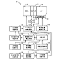
- FIG. 1 is a diagram illustrating a schematic configuration of a power transmission path from an engine 14 to a drive wheel 34 constituting a hybrid vehicle 10 (hereinafter referred to as a vehicle 10) to which the present invention is applied, and a driving power source for traveling.
- a navigation 90 It is a figure explaining the principal part of the control system provided in the vehicle 10 for these.
- a vehicle power transmission device 12 (hereinafter referred to as a power transmission device 12) is arranged on the engine 14 side in a transmission case 20 (hereinafter referred to as a case 20) as a non-rotating member attached to a vehicle body by bolting or the like.
- the engine connecting / disconnecting clutch K0, the electric motor MG, the torque converter 16, the oil pump 22, the automatic transmission 18 and the like are provided in order.
- the power transmission device 12 includes a propeller shaft 26 connected to an output shaft 24 that is an output rotating member of the automatic transmission 18, a differential gear device (differential gear) 28 connected to the propeller shaft 26, and a differential thereof.
- a pair of axles 30 and the like connected to the gear device 28 are provided.
- the power transmission device 12 configured in this manner is suitably used for, for example, an FR (front engine / rear drive) type vehicle 10.
- FR front engine / rear drive
- the power of the engine 14 is transmitted from the engine connecting shaft 32 that connects the engine 14 and the engine connecting / disconnecting clutch K0 to the engine connecting / disconnecting clutch.
- the power is transmitted to the pair of drive wheels 34 through the K0, the torque converter 16, the automatic transmission 18, the propeller shaft 26, the differential gear device 28, the pair of axles 30, and the like sequentially.
- the torque converter 16 is a fluid transmission device that transmits the driving force input to the pump impeller 16a to the automatic transmission 18 side via a fluid.
- the pump impeller 16a is connected to the engine 14 through the engine connecting / disconnecting clutch K0 and the engine connecting shaft 32 in order, and the driving force from the engine 14 is input and the input side is rotatable about the axis. It is a rotating element.
- the turbine impeller 16b of the torque converter 16 is an output side rotating element of the torque converter 16, and is connected to a transmission input shaft 36, which is an input rotating member of the automatic transmission 18, so as not to be relatively rotatable by spline fitting or the like. .
- the electric motor MG is a so-called motor generator having a function as a motor that generates a mechanical driving force from electric energy and a function as a generator that generates electric energy from mechanical energy.
- the electric motor MG is driven by electric energy supplied from the power storage device 54 via the inverter 52 as an alternative to the engine 14 or in addition to the engine 14 to generate a driving force for driving. Can function as a power source.
- electric energy is generated by regeneration from the driving force generated by the engine 14 or the driven force (mechanical energy) input from the driving wheel 34 side, and the electric energy is transmitted to the power storage device 54 via the inverter 52. Perform operations such as accumulating.
- the electric motor MG is operatively connected to the pump impeller 16a, and power is transmitted between the electric motor MG and the pump impeller 16a. Therefore, similarly to the engine 14, the electric motor MG is connected to the transmission input shaft 36 so that power can be transmitted.
- the oil pump 22 is connected to the pump impeller 16a, and controls the shift of the automatic transmission 18, controls the engagement / release of the engine connecting / disconnecting clutch K0, and is connected to each part of the power transmission path of the vehicle 10.
- This is a mechanical oil pump that is generated by rotationally driving hydraulic pressure for supplying lubricating oil by the engine 14 (or the electric motor MG).
- the engine connecting / disconnecting clutch K0 is, for example, a wet multi-plate hydraulic friction engagement device in which a plurality of friction plates stacked on each other are pressed by a hydraulic actuator, and the hydraulic pressure generated by the oil pump 22 is used as a source pressure.
- Engagement release control is performed by a hydraulic control circuit 50 provided in the power transmission device 12.
- the torque capacity capable of transmitting the power of the engine connecting / disconnecting clutch K0 that is, the engaging force of the engine connecting / disconnecting clutch K0 is continuously adjusted by adjusting the pressure of the linear solenoid valve or the like in the hydraulic control circuit 50, for example. Can be changed.
- the engine connecting / disconnecting clutch K0 includes a pair of clutch rotating members (clutch hub and clutch drum) that can rotate relative to each other in the released state, and one of the clutch rotating members (clutch hub) is the engine connecting shaft 32.
- the other of the clutch rotating members (clutch drum) is connected to the pump impeller 16a of the torque converter 16 so as not to be relatively rotatable.
- the engine connecting / disconnecting clutch K0 rotates the pump impeller 16a integrally with the engine 14 via the engine connecting shaft 32 in the engaged state. That is, in the engaged state of the engine connecting / disconnecting clutch K0, the driving force from the engine 14 is input to the pump impeller 16a.
- the automatic transmission 18 is connected to the electric motor MG so as to be able to transmit power without going through the engine connecting / disconnecting clutch K0, and constitutes a part of the power transmission path from the engine 14 to the drive wheels 34. Power from the engine 14 and the electric motor MG is transmitted to the drive wheel 34 side.
- the automatic transmission 18 is changed in speed by re-holding one of a plurality of hydraulic friction engagement devices such as the clutch C and the brake B (that is, by engagement and release of the hydraulic friction engagement device).
- This is a planetary gear type multi-stage transmission that functions as a stepped automatic transmission in which a plurality of shift stages (gear stages) are selectively established.
- the automatic transmission 18 is a stepped transmission that performs a so-called clutch-to-clutch shift that is often used in known vehicles, and shifts the rotation of the transmission input shaft 36 and outputs it from the output shaft 24.
- the transmission input shaft 36 is also a turbine shaft that is rotationally driven by the turbine impeller 16 b of the torque converter 16.
- a predetermined gear stage (shift stage) is established according to the accelerator operation of the driver, the vehicle speed V, and the like by the engagement release control of the clutch C and the brake B.
- the navigation 90 includes a storage medium 92 such as a CD-ROM, DVD-ROM, or HDD (hard disk drive), for example, and a known navigation using a road map database (hereinafter referred to as map data) stored in the storage medium 92. It has a function to execute control.
- FIG. 2 is a conceptual diagram showing an example of map data stored in the storage medium 92. 2, (a) is a diagram showing a plurality of nodes as arbitrary points specified by the map data and links as a plurality of sections connecting the respective nodes specified by the map data, (b) These are figures which show the data tables, such as traveling path information memorize
- an ID address is determined for each link, and for each link ID, the start point coordinates and end point coordinates defined by the node, as travel path information (road information)
- travel path information road information
- road information Road gradient, altitude information, road curvature, road types such as general roads (prefectural roads / prefectural roads / city roads / narrow streets), highways and one-way streets, width information, intersection information, and the like are stored.
- the map data such as each node, link ID, and travel route information stored in the storage medium 92 is, for example, normally rewritable fixed information. However, a medium such as a CD-ROM or DVD-ROM may be replaced, Updating is possible by rewriting the contents of the HDD using update software.
- the vehicle 10 is provided with an electronic control device 100 including a control device related to, for example, hybrid drive control.
- the electronic control device 100 includes, for example, a so-called microcomputer having a CPU, a RAM, a ROM, an input / output interface, and the like, and the CPU uses a temporary storage function of the RAM according to a program stored in the ROM in advance.
- Various controls of the vehicle 10 are executed by performing signal processing.
- the electronic control unit 100 performs output control of the engine 14, drive control of the electric motor MG including regeneration control of the electric motor MG, shift control of the automatic transmission 18, torque capacity control of the engine connecting / disconnecting clutch K0, and the like. It is configured separately for engine control, motor control, hydraulic control (shift control), etc. as necessary.
- an engine signal indicative of the engine rotational speed N E is the rotational speed of the engine 14 detected by the rotational speed sensor 56, a turbine rotational speed sensor 58 automatic transmission 18 detected by As a signal indicating the turbine rotational speed NT of the torque converter 16, that is, the transmission input rotational speed N IN which is the rotational speed of the transmission input shaft 36, and the vehicle speed V as a vehicle speed related value detected by the output shaft rotational speed sensor 60.
- Signal representing the throttle valve opening theta TH is, a signal representing the intake air quantity Q AIR of the engine 14 detected by an intake air amount sensor 66, longitudinal acceleration G (or down front and rear of the vehicle 10 detected by the acceleration sensor 68 signal representing the velocity G), the cooling water temperature TH W signal representative of the signal representative of the oil temperature TH oIL of the working oil in the hydraulic control circuit 50 detected by the oil temperature sensor 72 of the engine 14 detected by a coolant temperature sensor 70 , A signal indicating the accelerator opening Acc, which is an operation amount of the accelerator pedal 76 as a driving force request amount (driver request output) to the vehicle 10 detected by the driver, detected by the accelerator opening sensor 74, and detected by the foot brake sensor 78.
- the driver operates the brake pedal 80 as a braking force request amount (driver required deceleration) for the vehicle 10.
- a signal representing the brake operation amount Bra which is a quantity, a lever position of the shift lever 84 such as a known “P”, “N”, “D”, “R”, “S” position detected by the shift position sensor 82 ( shift operating position, shift position, a signal representative of the operating position) P SH, the battery temperature TH BAT and the battery output current (battery charge and discharge current) I BAT and the battery voltage V BAT of the power storage device 54 detected by the battery sensor 86
- a signal to be displayed, a car navigation information signal Snavi representing map data from the navigation 30 mounted on the vehicle 10, and the like are supplied.
- the electronic control device 100 sequentially calculates the state of charge (charge capacity) SOC of the power storage device 54 based on, for example, the battery temperature TH BAT , the battery charge / discharge current I BAT , and the battery voltage V BAT .
- the electronic control unit 100 also outputs, for example, an engine output control command signal S E for controlling the output of the engine 14, an electric motor control command signal S M for controlling the operation of the electric motor MG, an engine connecting / disconnecting clutch K0, and an automatic a hydraulic command signal S P output for operating the solenoid valve included in the hydraulic control circuit 50 to control the hydraulic actuators of clutches C and brakes B of the transmission 18 (solenoid valve) and the like are outputted.
- an engine output control command signal S E for controlling the output of the engine 14
- an electric motor control command signal S M for controlling the operation of the electric motor MG
- an engine connecting / disconnecting clutch K0 an automatic a hydraulic command signal S P output for operating the solenoid valve included in the hydraulic control circuit 50 to control the hydraulic actuators of clutches C and brakes B of the transmission 18 (solenoid valve) and the like are outputted.
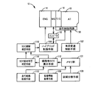
- FIG. 3 is a functional block diagram for explaining a main part of the control function by the electronic control device 100.
- the stepped shift control unit that is, the stepped shift control unit 102 functions as a shift control unit that shifts the automatic transmission 18.
- the stepped speed change control means 102 determines the actual vehicle speed V from a known relationship (shift diagram, shift map) stored in advance with the vehicle speed V and the accelerator opening Acc (or the transmission output torque T OUT or the like) as variables. and it performs shift determination based on the vehicle condition represented by the accelerator opening Acc, and outputs a hydraulic pressure command signal S P to perform the automatic shift control of the automatic transmission 16 as the determined gear position is obtained.
- the hybrid control unit that is, the hybrid control unit 104, functions as an engine drive control unit that controls the drive of the engine 14 and a motor operation control unit that controls an operation as a driving force source or a generator by the motor MG via the inverter 52.
- the hybrid drive control by the engine 14 and the electric motor MG is executed by these control functions.
- the hybrid control means 104 the target value of the driving torque T D is a vehicle required torque i.e.
- torque T D * is traveling drive force source obtained by calculating (the engine 14 and the motor MG) output torque or transmission input torque T target value of the AT (target transmission input torque T AT *), the target transmission The driving force source for traveling is controlled so that the input torque T AT * is obtained.
- the hybrid control means 104 sets the travel mode to the motor travel mode when, for example, the target drive torque T D * (target transmission input torque T AT * ) is within a range that can be covered only by the motor torque T MG. (Hereinafter referred to as EV mode), and motor travel (EV travel) is performed using only the electric motor MG as a driving force source for travel.
- the hybrid control unit 104 sets the travel mode to the engine travel mode, that is, the hybrid travel mode (hereinafter referred to as HV). Mode), at least engine driving using the engine 14 as a driving force source for driving, that is, hybrid driving (HV driving) is performed.
- the hybrid control means 104 When performing HV traveling, the hybrid control means 104 engages the engine connecting / disconnecting clutch K0 to transmit the driving force from the engine 14 to the pump impeller 16a, and also assists the motor MG as needed. Assisted traveling is performed with the output of. On the other hand, when performing EV traveling, the hybrid control means 104 releases the engine connecting / disconnecting clutch K0 to cut off the power transmission path between the engine 14 and the torque converter 16 and also causes the electric motor MG to perform EV traveling. The motor torque MG necessary for the operation is output.
- the hybrid control means 104 the accelerator pedal 76 during EV traveling is further depressed to increase the target driving torque T D *, the target driving torque T D * to the corresponding target transmission input torque T AT *
- a predetermined EV running torque range determined in advance as a torque that can be carried by the motor torque MG is exceeded, the running mode is switched from the EV mode to the HV mode, and the engine 14 is started to perform HV running. .
- the hybrid control means 104 is then the releasing accelerator pedal 76 is in the HV travel operation decreases the target drive torque T D *, the target transmission input torque T AT * becomes the predetermined EV running torque range If this happens, the travel mode is switched from the HV mode to the EV mode, the engine 14 is stopped, and EV travel is performed.
- the charge capacity SOC of the power storage device 54 is controlled so as to be kept within the range of the SOC management width that is obtained in advance and set as a predetermined range for suppressing the deterioration of the durability of the power storage device 54 that repeats charging and discharging. Is done.
- the SOC management width for example, a management width upper limit value that is a predetermined charge capacity upper limit value that is obtained and set in advance as an upper limit value of the charge capacity SOC that is allowed to charge the power storage device 54, and discharge of the power storage device 54.
- the range is defined by a management width lower limit value that is a predetermined charge capacity lower limit value that is obtained and set in advance as a lower limit value of the allowable charge capacity SOC.
- the amount of electric energy to be consumed is consumed in advance by EV traveling or assist traveling to reduce the charge capacity SOC of the power storage device 54.
- a traveling state in which the regenerative energy can be recovered unless a single traveling route is specified.
- the specified travel route is deviated during traveling, the amount of electric energy consumed in advance may not be collected, and there is a possibility that the power will fail. Therefore, in this embodiment, in order to improve fuel efficiency, a method is proposed that enables EV travel and assist travel without causing power failure without specifying a single travel route. The method will be described in detail below.
- Various information acquisition units that is, various information acquisition means 106, include position information detected using a positioning system using a satellite such as a known GPS (Global Positioning System) and a known INS (Inertial Navigation System).
- the current position information and vehicle traveling direction information of the vehicle 10 map-matched by the navigation 90 on the road map in the map data stored in the storage medium 92 based on the position information detected using the inertial navigation device) get.
- the section dividing unit that is, the section dividing means 108 divides the travel route obtained from the map data stored in the storage medium 92 into a plurality of sections, and stores the divided sections in the memory unit 101 in the electronic control unit 100.
- the section dividing means 108 can convert the road on the road map in the map data corresponding to the currently running road to the branch point where the branch road exists on the road based on the intersection information in the map data.
- section ID are assigned with an ID address (section ID).
- the section division (section section) based on the branch point it is difficult to reflect the difference in road surface gradient ⁇ that easily affects the change amount of the charge capacity SOC of the power storage device 54 (hereinafter, charge capacity change amount ⁇ SOC).
- the section dividing means 108 further divides the section according to the change amount of the road surface gradient ⁇ and the change amount of the altitude H based on the road surface gradient and the elevation information in the map data.
- the road surface gradient ⁇ may be calculated each time by the electronic control device 100 based on the altitude information.
- the various information acquisition means 106 further acquires the current (actual) charge capacity SOC of the power storage device 54. Further, the various information acquisition means 106 acquires an actual measurement value of the charge capacity change amount ⁇ SOC for each of the plurality of sections divided by the section dividing means 108 based on the charge capacity SOC, and sets the section ID for each section.
- the string is added (associated) and stored in the memory unit 101. If the vehicle travels the same section many times, statistical processing (for example, calculation of an average value) may be performed and stored.
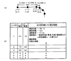
- FIG. 4 is a conceptual diagram showing an example when the traveling road R is divided into a plurality of sections.
- 4A is a diagram showing a section ID given by section division reflecting road surface gradient ⁇ and the like
- FIG. 4B is a data table of charge capacity change amount ⁇ SOC for each section stored in the memory unit 101.
- FIG. 4 in addition to being divided into sections at the branch points based on the intersection information stored in the storage medium 92, the sections are divided into division points set according to changes in the road surface gradient ⁇ . Yes.
- a section ID is determined for each of the plurality of divided sections, and the charge capacity change amount ⁇ SOC is stored for each section ID.
- the travel route acquisition unit that is, the travel route acquisition means 110 acquires, from the map data stored in the storage medium 92, any travel route that may travel from the current position of the vehicle 10 to a predetermined distance.
- the travel route acquisition unit 110 is based on the current position information of the vehicle 10 and the vehicle traveling direction information, and a branch point existing on the traveling path in the traveling direction from the current position of the vehicle 10 (that is, an intersection stored in the storage medium 92).
- a travel route that increases so as to branch at a branch point based on information) is acquired.
- the predetermined distance may be a sufficient fixed distance obtained in advance to obtain a fuel efficiency effect, taking into account, for example, that the charging capacity SOC of the power storage device 54 is consumed in advance by EV traveling or assist traveling as described above. .
- the predetermined distance is, for example, a distance until at least one travel route in a travel state that cannot be recovered as regenerative energy and is discarded among travel routes acquired by the travel route acquisition unit 110 exists. good.
- the travel route acquisition unit 110 includes a branch destination in which road information such as road type (road attribute) and width information differs from the branch source by a predetermined amount, a branch destination in which a past travel history (past travel history) is a predetermined value, and / or Alternatively, a travel route having a possibility of traveling is acquired by excluding a branch destination whose direction when traveling to a branch destination differs from the current traveling direction of the vehicle by a predetermined amount or more.
- the travel route acquisition unit 110 compares the road information of the branch source and the branch destination to determine whether or not the road information is different from a predetermined value. If the road information is different from the predetermined value, the branch destination is excluded from the route candidates. Therefore, it is not acquired as a travel route that may travel.
- the case where the difference is more than the predetermined is, for example, a case where there is a predetermined road type difference or a predetermined width difference which is greater than a preset branch destination having a low driving possibility with respect to the branch source.
- this predetermined road type difference for example, when the branching source is a national road or a prefectural road, the branch destination is a narrow street or the like.
- the travel route acquisition unit 110 determines whether or not the past travel history of the branch destination is equal to or less than a predetermined value, and if it is equal to or less than the predetermined value, the travel destination is excluded from the route candidates and travel that may be possible to travel. Do not get as a route.
- the case of the predetermined value or less is, for example, a case where the value is equal to or less than a predetermined past travel history set in advance as a branch destination having a low travel possibility.
- the past travel history is stored in the memory unit 101 as the number of travels attached to the section ID as shown in FIG. 4B, for example. Is counted up by various information acquisition means 106. Since the section ID is also divided by the dividing point as described above, the past traveling history is the same in the section ID between the branch point where the branch destination exists and the next branch point.
- the travel route acquisition unit 110 determines whether or not the direction when traveling to the branch destination differs from the current vehicle traveling direction by a predetermined amount or more, and excludes the branch destination from the route candidates when the direction is different by a predetermined amount or more. It is not acquired as a travel route that may travel.
- the case where the difference is more than the predetermined is a case where there is a predetermined difference in the traveling direction that is set in advance as a branch destination having a low possibility of traveling with respect to the branch source, for example.
- this predetermined traveling direction difference for example, the traveling direction of the branch destination differs from the traveling direction of the branch source by ⁇ 2 ⁇ / 3 or more.
- the per-route SOC calculation unit that is, the per-route SOC calculation means 112 charges each travel route that may be traveled, acquired by the travel route acquisition means 110, based on the charge capacity change amount ⁇ SOC stored for each section ID.
- the change characteristic of the capacity SOC is calculated in association with the distance from the current position.
- the change characteristic of the charge capacity SOC is a characteristic obtained by calculating a change in the accumulated value of the charge capacity change amount ⁇ SOC in the travel route obtained with respect to the current charge capacity SOC, using the distance as a variable.
- the SOC recovery availability determination unit that is, the SOC recovery availability determination unit 114, travels in a travel state in which the travel route acquired by the travel route acquisition unit 110 may be traveled and cannot be recovered as regenerative energy.
- the charging for each travel route calculated by the per-route SOC calculation means 112 determines whether or not there is at least one travel route that can recover the electric energy to the extent that the control range of the charge capacity SOC is exceeded. Judgment is made from the change characteristic of the capacity SOC. Further, the SOC recovery possibility determination means 114 calculates the position on the road map where the excess part is present on the travel route where there is a part exceeding the upper limit of the management width, and the regenerative energy amount at the part exceeding it as the estimated SOC recovery amount. To do. That is, the SOC recovery possibility determination means 114 determines whether or not there is a possibility of recovering electrical energy exceeding the management width upper limit value of the charge capacity SOC in any one of the travel routes that are likely to travel.
- the SOC failure determination unit that is, the SOC failure determination means 116, is acquired by the travel route acquisition means 110 even if the estimated SOC recovery amount is consumed before the recovery when the SOC recovery possibility determination means 114 determines that there is a recovery possibility. It is determined whether or not any of the travel routes that are likely to travel does not fall below the lower limit of the management width of the charge capacity SOC. In other words, the SOC failure determination means 116 can manage the charge capacity SOC even if the estimated SOC recovery amount is consumed in advance on a travel route other than the travel route that is predicted to be recovered by the SOC recovery possibility determination means 114. It is determined whether it does not fall below the lower limit and does not fail in terms of power.
- the EV control or the assist travel using the consumable amount based on the estimated SOC recovery amount (that is, the consumable amount is determined). (EV driving or assisting driving) is permitted. Then, the hybrid control means 104 executes the EV traveling or the assist traveling so that the above consumable amount is consumed before the start of collecting the electric energy.
- the consumable amount may be determined by the SOC failure determination means 116 not to fail in terms of power. For example, it is basically the estimated SOC recovery amount, but in consideration of calculation errors and variations, The smaller one of the estimated SOC recovery amount and (current charge capacity SOC-management width lower limit value) may be set as the consumable amount.
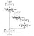
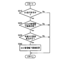
- FIG. 5 shows a control operation of the electronic control unit 100, that is, control for improving fuel efficiency by enabling EV driving and assist driving without causing power failure without specifying one driving route. It is a flowchart explaining the operation, and is repeatedly executed with a very short cycle time of, for example, about several milliseconds to several tens of milliseconds.
- FIG. 6 is an auxiliary flowchart executed when the control operation shown in the flowchart of FIG. 5 is executed.
- FIG. 7 is a conceptual diagram showing an example when the control operation shown in the flowchart of FIG. 5 is executed.
- step (hereinafter, step is omitted) S10 corresponding to the travel route acquisition unit 110 for example, any travel route that may travel from the current position of the vehicle 10 to a predetermined distance. It is acquired from the map data stored in the storage medium 92.
- step (hereinafter, step is omitted) S10 corresponding to the travel route acquisition unit 110 for example, any travel route that may travel from the current position of the vehicle 10 to a predetermined distance. It is acquired from the map data stored in the storage medium 92.
- the flowchart of FIG. 6 is executed and the road information such as the road type and the width information is different from the branch source by a predetermined amount or more, a branch destination whose past travel history is a predetermined branch destination or less, and a direction when proceeding to the branch destination Branch destinations that differ from the current traveling direction of the vehicle by a predetermined amount or more are excluded.
- S ⁇ b> 110 road information such as the road type and width information of the traveling road corresponding to the branch destination is acquired from the map data stored in the storage medium 92.
- S120 it is determined whether the branch destination road information is different from the branch source road information by a predetermined amount or more.
- S130 the number of travels on the travel route (section) corresponding to the branch destination is acquired from the data stored in the memory unit 101.
- S140 it is determined whether the past travel history at the branch destination is equal to or less than a predetermined value.
- S150 the direction when traveling to the travel path corresponding to the branch destination is acquired from the map data stored in the storage medium 92.
- S160 it is determined whether the direction when traveling to the branch destination is different from the current traveling direction of the vehicle by a predetermined amount or more. If the determination in S160 is negative, this routine is terminated. On the other hand, if any of S120, S140, and S160 is affirmed, a travel route in which the affirmed branch destination is acquired in S10 in the flowchart of FIG. Excluded from candidates.
- the travel routes A, B, and C (solid lines) shown in FIGS. 7A and 7B are examples of travel routes that may be traveled acquired in S10.
- a travel route D two-dot chain line
- FIG. 7A is an example of a branch destination that is excluded from a travel route that may travel because the road information differs from the branch source by a predetermined amount or more.
- the travel route E (two-dot chain line) shown in FIG. 7A is a branch destination that is excluded from the travel route that may travel because the direction when traveling is different from the traveling direction of the current vehicle by a predetermined amount or more. It is an example. Note that steps S110 to S170 in the flowchart of FIG. 6 correspond to the travel route acquisition unit 110, respectively.
- the position on the travel route exceeding the management width upper limit value and the estimated SOC recovery amount are calculated.
- the arrow A part is a part that cannot be recovered as regenerative energy and is discarded, and when this part is present, the travel route A is determined as “possible recovery”. If the determination in S30 is negative, the present routine is terminated. If the determination is affirmative, in S40 corresponding to the SOC failure determination means 116, for example, in a travel route other than the travel route that is considered to have a recovery possibility.
- the estimated SOC recovery amount is consumed before (in advance) the recovery, it is determined whether or not it does not fall below the management width lower limit value of the charge capacity SOC and does not fail in terms of power.
- FIG. 7C when it is determined that the travel route A is “possible collection”, paying attention to the other travel routes B and C, the estimated SOC collection amount is consumed in advance (by the collection start point). In this case, it is determined whether or not the traveling routes B and C do not fail in terms of power.
- the travel routes B ′ and C ′ (broken line) in FIG. 7D correspond to the case where the estimated SOC recovery amount has been consumed in advance, and in this case, it does not fall below the management width lower limit value of the charge capacity SOC.
- S40 determines whether it will fail. If the determination in S40 is negative, this routine is terminated. If the determination is affirmative, in S50 corresponding to the hybrid control means 104, the SOC recovery is performed up to the point where SOC recovery (electric energy recovery) is started. EV travel or assist travel is permitted so that a consumable amount based on the expected amount can be consumed.
- the target value of the control of the charge capacity SOC is changed from the median value of the SOC management range to “current charge capacity SOC ⁇ consumable amount” or EV running or Assist driving may be performed.
- the EV travel or the assist travel may be performed at a timing at which the above consumable amount can be consumed by calculating backward from the general consumption speed (discharge speed) during the EV travel or the assist travel.
- the travel route obtained from the map data stored in the storage medium 92 is divided into a plurality of sections, and the charge capacity change amount ⁇ SOC of the power storage device 54 for each of the divided sections. Therefore, the amount of electrical energy of the power storage device 54 that can be consumed prior to the collection of electrical energy when traveling on a certain travel route can be calculated based on the stored charge capacity change amount ⁇ SOC. And the electric energy amount (regenerative energy amount) collect
- any travel route that may travel from the current position of the vehicle 10 to a predetermined distance is acquired from the map data, and based on the charge capacity change amount ⁇ SOC,
- the change characteristic of the charge capacity SOC is calculated in association with the distance from the current position for each travel route, and electric energy is recovered to the extent that it exceeds the control width upper limit value of the charge capacity SOC as judged from the change characteristic of the charge capacity SOC. Even if there is at least one of the travel routes that can be traveled and the electric energy that exceeds the upper limit of the management width is consumed before the recovery, there is a possibility of travel.
- the section is divided based on a branch point where a branch path exists in the travel path, and thus the travel path obtained from the map data is appropriately divided into a plurality of sections. Further, since the section is divided according to the amount of change in the road surface gradient ⁇ and the amount of change in the altitude H based on the road surface gradient and altitude information in the map data, there are a plurality of travel routes obtained from the map data. Divide more appropriately into sections.
- the travel route with the possibility of traveling is a case where the road type is different from the branch source by a predetermined amount or more, a branch destination whose past travel history is a predetermined branch destination or less, and a branch destination. Since the direction is acquired by excluding a branch destination whose direction is different from the traveling direction of the current vehicle by a predetermined amount or more, the travel probability is low as judged from the road type of the front branch road while including all possible travel routes.
- the management width lower limit value of the charge capacity SOC is set due to variations in travel conditions and the like. If it falls below, there is a possibility that the fuel consumption may deteriorate due to entering a forced charging mode in which the power storage device 54 is forcibly charged. On the other hand, during traveling in which EV traveling or assist traveling is permitted, this is a traveling route from which electric energy can be sufficiently recovered.
- the management width lower limit value is temporarily set on the condition that the charge capacity SOC will increase in the travel route currently being traveled. Make it smaller.
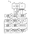
- FIG. 8 is a functional block diagram for explaining a main part of the control function by the electronic control unit 100, and is different from FIG. 3 in which a new function is added to the functional block diagram of FIG. This is an example.
- the EV traveling permission determining unit that is, the EV traveling permission determining means 118 determines whether the EV traveling that consumes the consumable amount or the EV traveling permitted for the assist traveling or the assist traveling is performed. To do.
- the current charging capacity SOC is calculated. It is determined whether or not it is in the vicinity of a predetermined capacity difference or less with respect to the management width lower limit value.
- the SOC recovery possibility determination means 114 determines whether or not the charge capacity SOC will increase in the future based on the change characteristics of the charge capacity SOC in each travel route that may travel from the currently traveled travel route. The determination of whether or not the charge capacity SOC increases is changed according to, for example, how to set the change amount (reduction amount) of the management width lower limit value by the management width lower limit value changing unit 122 described later. For example, when the change amount of the management width lower limit value is the minimum value of the future increase amount of the charge capacity SOC, it is determined whether or not the charge capacity SOC increases as it is. On the other hand, when the change amount of the management width lower limit value is a predetermined fixed value or a variable value corresponding to the distance, it is determined whether or not the charge capacity SOC increases more than the change amount of the management width lower limit value. .
- the management width lower limit value changing unit that is, the management width lower limit value changing unit 122 temporarily changes (decreases) the management width lower limit value when the SOC recovery possibility determination unit 114 determines that the charge capacity SOC will increase in the future.
- FIG. 9 is a flowchart for explaining a main part of the control operation of the electronic control unit 100, that is, a control operation for improving the fuel consumption by making it difficult to enter the forced charging mode. For example, an extremely short cycle of about several milliseconds to several tens of milliseconds It is executed repeatedly in time.
- S210 corresponding to the EV traveling permission determining means 118 it is determined whether the EV traveling that consumes the consumable amount or the EV traveling permitted for the assist traveling or the assist traveling is performed. Is done. If the determination in S210 is negative, this routine is terminated. If the determination is affirmative, in S220 corresponding to the management width lower limit vicinity determining unit 120, for example, the current charge capacity SOC is compared with the management width lower limit. It is determined whether or not it is in the vicinity of a predetermined capacity difference or less. If the determination in S220 is negative, this routine is terminated.
- S230 corresponding to the SOC recovery possibility determination means 114, for example, each travel that may travel from the currently traveled travel route. It is determined whether or not the charge capacity SOC will increase in the future based on the change characteristic of the charge capacity SOC in the route. If the determination in S230 is negative, this routine is terminated. If the determination is positive, in S240 corresponding to the management width lower limit changing means 122, for example, the management width lower limit is temporarily changed (reduced). .
- Travel with possibility of travel acquired by travel route acquisition means 110 during EV travel or assist travel in which EV travel that consumes the consumable amount executed in the first embodiment or assist travel is permitted When the vehicle deviates from the route, that is, when the vehicle travels on a travel route other than the travel route with the possibility of travel after EV travel or assist travel is permitted, the power storage device 54 is charged by pre-consumption of the electric energy amount by the EV travel or assist travel. There is a possibility that the capacity SOC falls below the management width lower limit. Therefore, in this embodiment, in order to avoid a failure in terms of electric power, permission for EV traveling or assist traveling is canceled when traveling other than the travel route with the possibility of traveling is performed. Further, EV travel or assist travel is not permitted until the charge capacity SOC is restored to a normal level (for example, the median value of the SOC management range).
- a normal level for example, the median value of the SOC management range
- FIG. 10 is a functional block diagram for explaining a main part of the control function by the electronic control unit 100, and is different from FIG. 3 in which a new function is added to the functional block diagram of FIG. This is an example.
- the route departure determination unit that is, the route departure determination unit 124
- the route departure determination unit 124 is acquired by the travel route acquisition unit 110 when the EV travel permission determination unit 118 determines that the EV travel is being performed or the assist travel is being performed. It is determined based on the current position information of the vehicle 10 whether or not the vehicle has deviated from the travel route that may have traveled.
- Hybrid control means 104 cancels permission of EV travel or assist travel that consumes the consumable amount, and executes normal control excluding EV travel or assist travel control that consumes the consumable amount. In addition, the hybrid control means 104 determines that the charge capacity SOC has been recovered to the normal level by the SOC recovery determination means 126 described later after once canceling the permission of EV travel or assist travel that consumes the consumable amount. Until then, EV travel or assist travel that consumes the consumable amount is not permitted.
- the SOC recovery determination unit that is, the SOC recovery determination means 126 determines whether or not the charge capacity SOC has recovered to a normal level (for example, the median value of the SOC management width) in the normal control.
- FIG. 11 is a flowchart for explaining a control operation of the electronic control device 100, that is, a control operation for avoiding power failure when electric energy cannot be recovered as expected. It is repeatedly executed with an extremely short cycle time of about several tens of msec.
- S310 corresponding to the EV traveling permission determining means 118 it is determined whether the EV traveling that consumes the consumable amount or the EV traveling permitted for the assist traveling or the assist traveling is performed. Is done. If the determination in S310 is negative, this routine is terminated. If the determination is affirmative, in S320 corresponding to the route departure determination unit 124, for example, whether or not the obtained travel route that may have traveled has been deviated. Is determined based on the current position information of the vehicle 10. If the determination in S320 is negative, this routine is terminated. If the determination is positive, in S330 corresponding to the hybrid control means 104, for example, permission for EV driving or assist driving that consumes the consumable amount is canceled.
- S340 corresponding to the SOC recovery determination means 126, it is determined whether or not the charge capacity SOC has been recovered to the normal level (for example, the median value of the SOC management width) by the normal control. If the determination in S340 is affirmed, this routine is terminated. If the determination is negative, in S350 corresponding to the hybrid control means 104, for example, EV travel or assist travel that consumes the consumable amount is not permitted. Next, S340 is executed again. In other words, until the determination in S340 is affirmed, EV traveling or assist traveling that consumes the consumable amount is not permitted in S350.
- Example of this invention was described in detail based on drawing, this invention can be implemented combining an Example mutually and is applied also in another aspect.
- each embodiment is implemented independently.
- the above embodiments are not necessarily implemented independently, and may be implemented in appropriate combination.
- the travel route with the possibility of travel may be configured by a section in which the charge capacity change amount ⁇ SOC is stored.
- the change characteristic of the charge capacity SOC is appropriately calculated for each travel route having the possibility of traveling, and the electric energy is increased to the extent that the control width upper limit value of the charge capacity SOC is exceeded from the change characteristic of the charge capacity SOC. It is appropriately determined whether or not there is at least one of the travel routes that can be recovered from the travel routes that may be traveled, and the amount that exceeds the upper limit of the management width from the change characteristics of the charge capacity SOC. Even if the electric energy is consumed before the recovery, it is appropriately determined whether or not the travel route with the possibility of traveling does not fall below the lower limit of the management width of the charge capacity SOC.
- the travel route by configuring the travel route with the travel possibility by the section in which the charge capacity change amount ⁇ SOC is stored, as a result, the section other than the section in which the charge capacity change amount ⁇ SOC is stored. In the case of traveling, permission for EV traveling or assist traveling is canceled.
- the charge capacity change amount ⁇ SOC in a certain section is acquired as an actual measurement value based on the charge capacity SOC, but is not limited thereto.
- accumulation of travel energy (position energy mgh + travel resistance Cd ⁇ projected area A ⁇ vehicle speed V 2 + rolling resistance) ⁇ charge efficiency ⁇ ; m is vehicle weight, g is gravitational acceleration, and h is altitude difference) in a certain section.
- the value may be calculated as a charge capacity change amount ⁇ SOC. Therefore, the estimated charge capacity change amount ⁇ SOC in a section where there is no travel history in the past and the charge capacity change amount ⁇ SOC is not stored may be calculated as the integrated value of the travel energy.
- the vehicle speed V is required in the calculation of the travel energy, for example, the legal vehicle speed in the section or the average vehicle speed in other similar road types is used as the vehicle speed V.
- the three determination conditions (steps S120, S140, and S160) for excluding the branch destination in the flowchart of FIG. 6 are OR conditions, but may be AND conditions.
- permission for EV traveling or assist traveling is canceled when traveling on a route other than a travel route that may be traveled.
- the present invention is not limited to this. For example, electric energy is assumed for some reason. When the street cannot be collected, permission for EV traveling or assist traveling may be canceled. Even if it does in this way, failure in terms of power can be avoided appropriately.
- Hybrid vehicle 14 Engine (driving drive power source) 54: Power storage device 100: Electronic control device (control device) MG: Electric motor (driving drive power source)
Abstract
Description
14:エンジン(走行用駆動力源)
54:蓄電装置
100:電子制御装置(制御装置)
MG:電動機(走行用駆動力源)
Claims (5)
- 蓄電装置の電気エネルギにより駆動される電動機を含む複数の走行用駆動力源を備え、該電動機を用いて走行するモータ走行或いはアシスト走行が可能なハイブリッド車両の制御装置であって、
地図データから得られる走行路を複数の区間に分割し、該分割した区間毎に前記蓄電装置の充電容量の変化量を記憶することを特徴とするハイブリッド車両の制御装置。 - 車両の現在位置から所定距離までの間で走行可能性のある走行経路の何れもを前記地図データから取得し、
前記充電容量の変化量に基づいて、前記走行経路毎に該充電容量の変化特性を現在位置からの距離に関連付けて算出し、
前記充電容量の変化特性から判断して、前記蓄電装置の充電が許可される所定充電容量上限値を超える程に電気エネルギを回収することができる走行経路が前記走行可能性のある走行経路のうちで少なくとも1つ存在し、且つ該所定充電容量上限値を超える分の電気エネルギを回収前に消費したとしても該走行可能性のある走行経路の何れにおいても該蓄電装置の放電が許可される所定充電容量下限値を下回らない場合には、該所定充電容量上限値を超える分の電気エネルギに基づく消費可能量を用いた前記モータ走行或いは前記アシスト走行を許可することを特徴とする請求項1に記載のハイブリッド車両の制御装置。 - 前記走行可能性のある走行経路以外の走行となった場合には、前記モータ走行或いは前記アシスト走行の許可を取り消すことを特徴とする請求項2に記載のハイブリッド車両の制御装置。
- 前記走行可能性のある走行経路は、前記充電容量の変化量が記憶されている区間により構成されることを特徴とする請求項2又は3に記載のハイブリッド車両の制御装置。
- 前記区間は、走行路において分岐路が存在する分岐点に基づいて分割されることを特徴とする請求項1乃至4の何れか1項に記載のハイブリッド車両の制御装置。
Priority Applications (5)
| Application Number | Priority Date | Filing Date | Title |
|---|---|---|---|
| JP2013500742A JP5700112B2 (ja) | 2011-02-21 | 2011-02-21 | ハイブリッド車両の制御装置 |
| US14/000,706 US9610934B2 (en) | 2011-02-21 | 2011-02-21 | Control device of hybrid vehicle |
| PCT/JP2011/053745 WO2012114446A1 (ja) | 2011-02-21 | 2011-02-21 | ハイブリッド車両の制御装置 |
| EP11859449.8A EP2679461B1 (en) | 2011-02-21 | 2011-02-21 | Control device of hybrid vehicle |
| CN201180068176.5A CN103384622B (zh) | 2011-02-21 | 2011-02-21 | 混合动力车辆的控制装置 |
Applications Claiming Priority (1)
| Application Number | Priority Date | Filing Date | Title |
|---|---|---|---|
| PCT/JP2011/053745 WO2012114446A1 (ja) | 2011-02-21 | 2011-02-21 | ハイブリッド車両の制御装置 |
Publications (1)
| Publication Number | Publication Date |
|---|---|
| WO2012114446A1 true WO2012114446A1 (ja) | 2012-08-30 |
Family
ID=46720266
Family Applications (1)
| Application Number | Title | Priority Date | Filing Date |
|---|---|---|---|
| PCT/JP2011/053745 WO2012114446A1 (ja) | 2011-02-21 | 2011-02-21 | ハイブリッド車両の制御装置 |
Country Status (5)
| Country | Link |
|---|---|
| US (1) | US9610934B2 (ja) |
| EP (1) | EP2679461B1 (ja) |
| JP (1) | JP5700112B2 (ja) |
| CN (1) | CN103384622B (ja) |
| WO (1) | WO2012114446A1 (ja) |
Cited By (10)
| Publication number | Priority date | Publication date | Assignee | Title |
|---|---|---|---|---|
| JP2014094724A (ja) * | 2012-11-12 | 2014-05-22 | Honda Motor Co Ltd | ハイブリッド車両 |
| WO2014177786A1 (fr) * | 2013-05-03 | 2014-11-06 | Renault S.A.S | Procede d'optimisation de la consommation energetique d'un vehicule hybride |
| US20150025727A1 (en) * | 2013-07-17 | 2015-01-22 | Volvo Car Corporation | Method for optimizing the power usage of a vehicle |
| JP2015080961A (ja) * | 2013-10-21 | 2015-04-27 | トヨタ自動車株式会社 | 移動支援装置、移動支援方法、及び運転支援システム |
| WO2015049572A3 (en) * | 2013-10-03 | 2015-06-18 | Toyota Jidosha Kabushiki Kaisha | Predictive and adaptative movement support apparatus, movement support method, and driving support system for a hybrid vehicle for mode driving section optimization |
| WO2015086227A1 (de) * | 2013-12-11 | 2015-06-18 | Volkswagen Aktiengesellschaft | Verfahren zum ermitteln eines fahrzustandes eines hybridfahrzeuges für streckensegmente einer vorausliegenden fahrstrecke und hybridfahrzeug |
| RU2581993C2 (ru) * | 2012-05-04 | 2016-04-20 | ФОРД ГЛОУБАЛ ТЕКНОЛОДЖИЗ, ЭлЭлСи | Способ работы транспортного средства с гибридным приводом (варианты) |
| WO2018096821A1 (ja) * | 2016-11-25 | 2018-05-31 | 株式会社デンソー | 車両の走行制御装置 |
| WO2020090341A1 (ja) * | 2018-10-31 | 2020-05-07 | パナソニックIpマネジメント株式会社 | 情報処理システム、制御装置、及び車両用電源システム |
| CN112977400A (zh) * | 2021-03-09 | 2021-06-18 | 北京汽车股份有限公司 | 一种用于混合动力汽车驱动系统的能量管理方法及系统 |
Families Citing this family (24)
| Publication number | Priority date | Publication date | Assignee | Title |
|---|---|---|---|---|
| US20130016851A1 (en) * | 2010-03-25 | 2013-01-17 | Pioneer Corporation | Pseudonoise generation device and pseudonoise generation method |
| US9242544B2 (en) * | 2011-09-23 | 2016-01-26 | Kanzaki Kokyukoki Mfg. Co., Ltd. | Vehicle with electric transaxle |
| JP5803645B2 (ja) * | 2011-12-15 | 2015-11-04 | アイシン・エィ・ダブリュ株式会社 | 評価表示システム、方法およびプログラム |
| KR101371463B1 (ko) * | 2012-09-06 | 2014-03-24 | 기아자동차주식회사 | 하이브리드 자동차의 배터리 충전 제어 방법 및 시스템 |
| JP6007929B2 (ja) * | 2014-02-24 | 2016-10-19 | トヨタ自動車株式会社 | 移動支援装置、移動支援方法、及び運転支援システム |
| US9327712B2 (en) * | 2014-04-22 | 2016-05-03 | Alcatel Lucent | System and method for control of a hybrid vehicle with regenerative braking using location awareness |
| SE539479C2 (sv) | 2014-07-07 | 2017-09-26 | Scania Cv Ab | Styrning av en förbränningsmotor i samband med frihjulning |
| SE539477C2 (sv) | 2014-07-07 | 2017-09-26 | Scania Cv Ab | Styrning av en förbränningsmotor i samband med frihjulning |
| SE538539C2 (sv) | 2014-07-07 | 2016-09-13 | Scania Cv Ab | Styrning av förberedande åtgärder i ett fordon |
| KR101573625B1 (ko) * | 2014-08-12 | 2015-12-01 | 현대자동차주식회사 | 하이브리드 차량의 변속 제어 장치 및 방법 |
| KR101601473B1 (ko) * | 2014-08-25 | 2016-03-09 | 현대자동차주식회사 | 하이브리드 차량용 배터리의 충방전 보정 제어 장치 및 방법 |
| CN104309605A (zh) * | 2014-09-02 | 2015-01-28 | 郑州宇通客车股份有限公司 | 基于gps地理信息的混合动力汽车节能控制方法 |
| EP2998178B1 (en) | 2014-09-17 | 2022-01-26 | Volvo Car Corporation | Vehicle control through machine learning |
| KR101655609B1 (ko) * | 2014-12-11 | 2016-09-07 | 현대자동차주식회사 | 하이브리드 자동차의 배터리 충전 상태 제어 장치 및 방법 |
| US9718456B2 (en) * | 2015-03-26 | 2017-08-01 | Ford Global Technologies, Llc | Torque assist based on battery state of charge allocation |
| KR101713752B1 (ko) * | 2015-10-28 | 2017-03-22 | 현대자동차 주식회사 | 차량의 변속 제어 장치 및 그 방법 |
| CN105501070B (zh) * | 2015-12-16 | 2018-09-25 | 中国北方车辆研究所 | 主动式电力驱动车辆供耗电平衡控制方法 |
| KR101755976B1 (ko) * | 2016-01-07 | 2017-07-07 | 현대자동차주식회사 | 배터리 과 방전 방어방법과 컨트롤러 및 하이브리드 차량 |
| JP6808014B2 (ja) * | 2017-02-21 | 2021-01-06 | 日立オートモティブシステムズ株式会社 | 駐車制御装置 |
| US10678234B2 (en) * | 2017-08-24 | 2020-06-09 | Tusimple, Inc. | System and method for autonomous vehicle control to minimize energy cost |
| JP6992419B2 (ja) * | 2017-11-08 | 2022-01-13 | トヨタ自動車株式会社 | 電動車両の電費予測方法、サーバおよび電動車両 |
| SE1751528A1 (en) * | 2017-12-12 | 2019-06-13 | Scania Cv Ab | Method and system for propelling a vehicle |
| KR20200071854A (ko) * | 2018-12-04 | 2020-06-22 | 현대자동차주식회사 | 차량의 멀티미디어 제어 장치 및 방법 |
| CN110040128A (zh) * | 2019-05-07 | 2019-07-23 | 上海爱驱汽车技术有限公司 | 混合动力能量供给控制方法、装置及系统 |
Citations (5)
| Publication number | Priority date | Publication date | Assignee | Title |
|---|---|---|---|---|
| JPH08331772A (ja) * | 1995-05-30 | 1996-12-13 | Toyota Motor Corp | 車載誘導機の制御装置 |
| JP2002036903A (ja) * | 2000-07-24 | 2002-02-06 | Toyota Motor Corp | 車両のエネルギー蓄積装置用制御装置 |
| JP2005160269A (ja) | 2003-11-28 | 2005-06-16 | Equos Research Co Ltd | 駆動制御装置、及びハイブリッド車両 |
| JP2010125868A (ja) * | 2008-11-25 | 2010-06-10 | Denso Corp | 充放電計画装置 |
| JP2010169423A (ja) | 2009-01-20 | 2010-08-05 | Aisin Aw Co Ltd | 走行案内装置、走行案内方法及びコンピュータプログラム |
Family Cites Families (7)
| Publication number | Priority date | Publication date | Assignee | Title |
|---|---|---|---|---|
| DE102005037553A1 (de) * | 2005-08-09 | 2007-02-15 | Robert Bosch Gmbh | Verfahren zur Ansteuerung eines Hybridfahrzeugs und Hybridfahrzeug |
| JP4314257B2 (ja) * | 2006-09-28 | 2009-08-12 | トヨタ自動車株式会社 | 車両の表示装置および車両の表示装置の制御方法、プログラム、およびプログラムを記録した記録媒体 |
| JP4862621B2 (ja) * | 2006-11-15 | 2012-01-25 | トヨタ自動車株式会社 | ハイブリッド車両およびその制御方法 |
| US7865298B2 (en) * | 2007-05-03 | 2011-01-04 | Ford Motor Company | System and method for providing route information to a driver of a vehicle |
| JP5045685B2 (ja) * | 2009-01-20 | 2012-10-10 | アイシン・エィ・ダブリュ株式会社 | 経路案内装置、経路案内方法及びコンピュータプログラム |
| JP4692646B2 (ja) * | 2009-02-04 | 2011-06-01 | 株式会社デンソー | 動力発生源制御装置 |
| JP2010264791A (ja) * | 2009-05-12 | 2010-11-25 | Toyota Central R&D Labs Inc | ハイブリッド車両の駆動制御装置及びプログラム |
-
2011
- 2011-02-21 CN CN201180068176.5A patent/CN103384622B/zh not_active Expired - Fee Related
- 2011-02-21 JP JP2013500742A patent/JP5700112B2/ja active Active
- 2011-02-21 US US14/000,706 patent/US9610934B2/en active Active
- 2011-02-21 EP EP11859449.8A patent/EP2679461B1/en active Active
- 2011-02-21 WO PCT/JP2011/053745 patent/WO2012114446A1/ja active Application Filing
Patent Citations (5)
| Publication number | Priority date | Publication date | Assignee | Title |
|---|---|---|---|---|
| JPH08331772A (ja) * | 1995-05-30 | 1996-12-13 | Toyota Motor Corp | 車載誘導機の制御装置 |
| JP2002036903A (ja) * | 2000-07-24 | 2002-02-06 | Toyota Motor Corp | 車両のエネルギー蓄積装置用制御装置 |
| JP2005160269A (ja) | 2003-11-28 | 2005-06-16 | Equos Research Co Ltd | 駆動制御装置、及びハイブリッド車両 |
| JP2010125868A (ja) * | 2008-11-25 | 2010-06-10 | Denso Corp | 充放電計画装置 |
| JP2010169423A (ja) | 2009-01-20 | 2010-08-05 | Aisin Aw Co Ltd | 走行案内装置、走行案内方法及びコンピュータプログラム |
Cited By (18)
| Publication number | Priority date | Publication date | Assignee | Title |
|---|---|---|---|---|
| RU2581993C2 (ru) * | 2012-05-04 | 2016-04-20 | ФОРД ГЛОУБАЛ ТЕКНОЛОДЖИЗ, ЭлЭлСи | Способ работы транспортного средства с гибридным приводом (варианты) |
| JP2014094724A (ja) * | 2012-11-12 | 2014-05-22 | Honda Motor Co Ltd | ハイブリッド車両 |
| WO2014177786A1 (fr) * | 2013-05-03 | 2014-11-06 | Renault S.A.S | Procede d'optimisation de la consommation energetique d'un vehicule hybride |
| FR3005296A1 (fr) * | 2013-05-03 | 2014-11-07 | Renault Sa | Procede d'optimisation de la consommation energetique d'un vehicule hybride |
| CN105246753A (zh) * | 2013-05-03 | 2016-01-13 | 雷诺股份公司 | 用于优化混合动力车辆的能量消耗的方法 |
| US20150025727A1 (en) * | 2013-07-17 | 2015-01-22 | Volvo Car Corporation | Method for optimizing the power usage of a vehicle |
| US9499161B2 (en) | 2013-10-03 | 2016-11-22 | Toyota Jidosha Kabushiki Kaisha | Predictive and adaptive movement support apparatus, movement support method, and driving support system for a hybrid vehicle for mode driving section optimization |
| WO2015049572A3 (en) * | 2013-10-03 | 2015-06-18 | Toyota Jidosha Kabushiki Kaisha | Predictive and adaptative movement support apparatus, movement support method, and driving support system for a hybrid vehicle for mode driving section optimization |
| CN105593096B (zh) * | 2013-10-03 | 2017-12-26 | 丰田自动车株式会社 | 用于混合动力车辆的模式驾驶区间优化的预测性且自适应性运动支持设备、运动支持方法以及驾驶支持系统 |
| CN105593096A (zh) * | 2013-10-03 | 2016-05-18 | 丰田自动车株式会社 | 用于混合动力车辆的模式驾驶区间优化的预测性且自适应性运动支持设备、运动支持方法以及驾驶支持系统 |
| JP2015080961A (ja) * | 2013-10-21 | 2015-04-27 | トヨタ自動車株式会社 | 移動支援装置、移動支援方法、及び運転支援システム |
| WO2015086227A1 (de) * | 2013-12-11 | 2015-06-18 | Volkswagen Aktiengesellschaft | Verfahren zum ermitteln eines fahrzustandes eines hybridfahrzeuges für streckensegmente einer vorausliegenden fahrstrecke und hybridfahrzeug |
| EP3333036A1 (de) * | 2013-12-11 | 2018-06-13 | Volkswagen Aktiengesellschaft | Verfahren zum ermitteln eines fahrzustandes eines hybridfahrzeuges für streckensegmente einer vorausliegenden fahrstrecke und hybridfahrzeug |
| WO2018096821A1 (ja) * | 2016-11-25 | 2018-05-31 | 株式会社デンソー | 車両の走行制御装置 |
| DE112017005969T5 (de) | 2016-11-25 | 2019-08-14 | Denso Corporation | Fahrzeugfahrsteuerungsvorrichtung |
| WO2020090341A1 (ja) * | 2018-10-31 | 2020-05-07 | パナソニックIpマネジメント株式会社 | 情報処理システム、制御装置、及び車両用電源システム |
| JP7373805B2 (ja) | 2018-10-31 | 2023-11-06 | パナソニックIpマネジメント株式会社 | 情報処理システム、制御装置、及び車両用電源システム |
| CN112977400A (zh) * | 2021-03-09 | 2021-06-18 | 北京汽车股份有限公司 | 一种用于混合动力汽车驱动系统的能量管理方法及系统 |
Also Published As
| Publication number | Publication date |
|---|---|
| CN103384622A (zh) | 2013-11-06 |
| JP5700112B2 (ja) | 2015-04-15 |
| US9610934B2 (en) | 2017-04-04 |
| EP2679461B1 (en) | 2019-04-17 |
| CN103384622B (zh) | 2016-09-07 |
| EP2679461A4 (en) | 2018-04-25 |
| EP2679461A1 (en) | 2014-01-01 |
| US20130332020A1 (en) | 2013-12-12 |
| JPWO2012114446A1 (ja) | 2014-07-07 |
Similar Documents
| Publication | Publication Date | Title |
|---|---|---|
| JP5700112B2 (ja) | ハイブリッド車両の制御装置 | |
| JP4909863B2 (ja) | ハイブリッド車両の制御装置 | |
| EP3153365B1 (en) | Hybrid vehicle control apparatus and hybrid vehicle including the control apparatus | |
| US9031727B2 (en) | Vehicle travel control apparatus | |
| JP2001169408A (ja) | ハイブリッド車両の制御装置 | |
| CN109941262A (zh) | 混合动力电动车辆及其搜索路径的方法 | |
| JP6813430B2 (ja) | 車両制御装置 | |
| JP2018103930A (ja) | ハイブリッド車両の制御装置 | |
| JP2014103771A (ja) | 電気自動車の回生制御装置 | |
| WO2017086435A1 (ja) | ハイブリッド車両の回生電力量制御システム、ハイブリッド車両及びハイブリッド車両の回生電力量制御方法 | |
| JP2017030595A (ja) | ハイブリッド車両及びその制御方法 | |
| JP2016175503A (ja) | ハイブリッド車両及びその制御方法 | |
| JP5780041B2 (ja) | 車両用制御装置 | |
| JP6551021B2 (ja) | ハイブリッド車両及びその制御方法 | |
| JP2016217851A (ja) | 車両質量推定装置および車両質量推定方法 | |
| JP2016175496A (ja) | ハイブリッド車両及びその制御方法 | |
| JP2016175502A (ja) | ハイブリッド車両及びその制御方法 | |
| JP6149879B2 (ja) | ハイブリッド車両の制御装置 | |
| JP2014097762A (ja) | 走行制御装置 | |
| JP2013169915A (ja) | ハイブリッド車両の制御装置 | |
| JP5803370B2 (ja) | 車両用の学習値更新制御装置 | |
| JP2016175505A (ja) | ハイブリッド車両及びその制御方法 | |
| JP2016175504A (ja) | ハイブリッド車両及びその制御方法 | |
| JP6593045B2 (ja) | ハイブリッド車両及びその制御方法 | |
| JP5618007B2 (ja) | 車両用走行制御装置 |
Legal Events
| Date | Code | Title | Description |
|---|---|---|---|
| 121 | Ep: the epo has been informed by wipo that ep was designated in this application |
Ref document number: 11859449 Country of ref document: EP Kind code of ref document: A1 |
|
| ENP | Entry into the national phase |
Ref document number: 2013500742 Country of ref document: JP Kind code of ref document: A |
|
| NENP | Non-entry into the national phase |
Ref country code: DE |
|
| WWE | Wipo information: entry into national phase |
Ref document number: 14000706 Country of ref document: US |
|
| WWE | Wipo information: entry into national phase |
Ref document number: 2011859449 Country of ref document: EP |