WO2012105052A1 - 二次電池 - Google Patents
二次電池 Download PDFInfo
- Publication number
- WO2012105052A1 WO2012105052A1 PCT/JP2011/052421 JP2011052421W WO2012105052A1 WO 2012105052 A1 WO2012105052 A1 WO 2012105052A1 JP 2011052421 W JP2011052421 W JP 2011052421W WO 2012105052 A1 WO2012105052 A1 WO 2012105052A1
- Authority
- WO
- WIPO (PCT)
- Prior art keywords
- active material
- electrode active
- material layer
- positive electrode
- negative electrode
- Prior art date
- Legal status (The legal status is an assumption and is not a legal conclusion. Google has not performed a legal analysis and makes no representation as to the accuracy of the status listed.)
- Ceased
Links
Images






Classifications
-
- H—ELECTRICITY
- H01—ELECTRIC ELEMENTS
- H01M—PROCESSES OR MEANS, e.g. BATTERIES, FOR THE DIRECT CONVERSION OF CHEMICAL ENERGY INTO ELECTRICAL ENERGY
- H01M10/00—Secondary cells; Manufacture thereof
- H01M10/04—Construction or manufacture in general
- H01M10/0431—Cells with wound or folded electrodes
-
- H—ELECTRICITY
- H01—ELECTRIC ELEMENTS
- H01M—PROCESSES OR MEANS, e.g. BATTERIES, FOR THE DIRECT CONVERSION OF CHEMICAL ENERGY INTO ELECTRICAL ENERGY
- H01M10/00—Secondary cells; Manufacture thereof
- H01M10/04—Construction or manufacture in general
- H01M10/0413—Large-sized flat cells or batteries for motive or stationary systems with plate-like electrodes
-
- H—ELECTRICITY
- H01—ELECTRIC ELEMENTS
- H01M—PROCESSES OR MEANS, e.g. BATTERIES, FOR THE DIRECT CONVERSION OF CHEMICAL ENERGY INTO ELECTRICAL ENERGY
- H01M10/00—Secondary cells; Manufacture thereof
- H01M10/05—Accumulators with non-aqueous electrolyte
- H01M10/052—Li-accumulators
- H01M10/0525—Rocking-chair batteries, i.e. batteries with lithium insertion or intercalation in both electrodes; Lithium-ion batteries
-
- H—ELECTRICITY
- H01—ELECTRIC ELEMENTS
- H01M—PROCESSES OR MEANS, e.g. BATTERIES, FOR THE DIRECT CONVERSION OF CHEMICAL ENERGY INTO ELECTRICAL ENERGY
- H01M4/00—Electrodes
- H01M4/02—Electrodes composed of, or comprising, active material
- H01M4/64—Carriers or collectors
- H01M4/70—Carriers or collectors characterised by shape or form
-
- H—ELECTRICITY
- H01—ELECTRIC ELEMENTS
- H01M—PROCESSES OR MEANS, e.g. BATTERIES, FOR THE DIRECT CONVERSION OF CHEMICAL ENERGY INTO ELECTRICAL ENERGY
- H01M4/00—Electrodes
- H01M4/02—Electrodes composed of, or comprising, active material
- H01M2004/021—Physical characteristics, e.g. porosity, surface area
-
- H—ELECTRICITY
- H01—ELECTRIC ELEMENTS
- H01M—PROCESSES OR MEANS, e.g. BATTERIES, FOR THE DIRECT CONVERSION OF CHEMICAL ENERGY INTO ELECTRICAL ENERGY
- H01M4/00—Electrodes
- H01M4/02—Electrodes composed of, or comprising, active material
- H01M2004/026—Electrodes composed of, or comprising, active material characterised by the polarity
- H01M2004/027—Negative electrodes
-
- H—ELECTRICITY
- H01—ELECTRIC ELEMENTS
- H01M—PROCESSES OR MEANS, e.g. BATTERIES, FOR THE DIRECT CONVERSION OF CHEMICAL ENERGY INTO ELECTRICAL ENERGY
- H01M10/00—Secondary cells; Manufacture thereof
- H01M10/42—Methods or arrangements for servicing or maintenance of secondary cells or secondary half-cells
- H01M2010/4292—Aspects relating to capacity ratio of electrodes/electrolyte or anode/cathode
-
- Y—GENERAL TAGGING OF NEW TECHNOLOGICAL DEVELOPMENTS; GENERAL TAGGING OF CROSS-SECTIONAL TECHNOLOGIES SPANNING OVER SEVERAL SECTIONS OF THE IPC; TECHNICAL SUBJECTS COVERED BY FORMER USPC CROSS-REFERENCE ART COLLECTIONS [XRACs] AND DIGESTS
- Y02—TECHNOLOGIES OR APPLICATIONS FOR MITIGATION OR ADAPTATION AGAINST CLIMATE CHANGE
- Y02E—REDUCTION OF GREENHOUSE GAS [GHG] EMISSIONS, RELATED TO ENERGY GENERATION, TRANSMISSION OR DISTRIBUTION
- Y02E60/00—Enabling technologies; Technologies with a potential or indirect contribution to GHG emissions mitigation
- Y02E60/10—Energy storage using batteries
-
- Y—GENERAL TAGGING OF NEW TECHNOLOGICAL DEVELOPMENTS; GENERAL TAGGING OF CROSS-SECTIONAL TECHNOLOGIES SPANNING OVER SEVERAL SECTIONS OF THE IPC; TECHNICAL SUBJECTS COVERED BY FORMER USPC CROSS-REFERENCE ART COLLECTIONS [XRACs] AND DIGESTS
- Y02—TECHNOLOGIES OR APPLICATIONS FOR MITIGATION OR ADAPTATION AGAINST CLIMATE CHANGE
- Y02P—CLIMATE CHANGE MITIGATION TECHNOLOGIES IN THE PRODUCTION OR PROCESSING OF GOODS
- Y02P70/00—Climate change mitigation technologies in the production process for final industrial or consumer products
- Y02P70/50—Manufacturing or production processes characterised by the final manufactured product
-
- Y—GENERAL TAGGING OF NEW TECHNOLOGICAL DEVELOPMENTS; GENERAL TAGGING OF CROSS-SECTIONAL TECHNOLOGIES SPANNING OVER SEVERAL SECTIONS OF THE IPC; TECHNICAL SUBJECTS COVERED BY FORMER USPC CROSS-REFERENCE ART COLLECTIONS [XRACs] AND DIGESTS
- Y02—TECHNOLOGIES OR APPLICATIONS FOR MITIGATION OR ADAPTATION AGAINST CLIMATE CHANGE
- Y02T—CLIMATE CHANGE MITIGATION TECHNOLOGIES RELATED TO TRANSPORTATION
- Y02T10/00—Road transport of goods or passengers
- Y02T10/60—Other road transportation technologies with climate change mitigation effect
- Y02T10/70—Energy storage systems for electromobility, e.g. batteries
Definitions
- the present invention relates to a secondary battery.
- second battery means a general electric storage device that can be repeatedly charged, so-called storage batteries such as lithium-ion secondary batteries, nickel-metal hydride batteries, nickel cadmium batteries, and the like. It is a term encompassing power storage elements such as electric double layer capacitors.
- lithium ion secondary battery refers to a secondary battery that uses lithium ions as electrolyte ions and is charged and discharged by the movement of electric charge accompanying the lithium ions between the positive and negative electrodes.
- Patent Document 1 discloses an invention of a so-called cylindrical secondary battery. That is, here, the secondary battery includes a positive electrode composed of a positive electrode active material layer formed by applying a positive electrode active material on both surfaces of a strip-shaped positive electrode current collector, and a negative electrode active material on both surfaces of the strip-shaped negative electrode current collector.
- the negative electrode which consists of a negative electrode active material layer formed by apply
- Such a positive electrode and a negative electrode are wound through a separator made of a polypropylene film to constitute a wound electrode body.
- the positive electrode active material layer is referred to as a “positive electrode mixture layer”.
- the negative electrode active material layer is referred to as a “negative electrode mixture layer”.
- Such a wound electrode body is housed in a battery container with insulators placed on the top and bottom.
- the negative electrode facing the positive electrode is formed larger than the positive electrode in terms of width and length.
- Patent Document 1 discloses that a portion of the negative electrode active material layer that does not face the positive electrode active material layer of the wound electrode body is covered with an insulating resin that is not soluble in the electrolytic solution. Thereby, the part coat
- Patent Document 2 is not directly related to Patent Document 1.
- Patent Document 2 discloses a secondary battery in which the width of the negative electrode active material layer is wider than that of the positive electrode active material layer in order to prevent deposition of metallic lithium.
- the negative electrode active material layer is overlaid so as to cover the positive electrode active material layer. According to such a secondary battery, for example, when lithium ions are released from the positive electrode active material layer during charging, the lithium ions are more reliably stored in the negative electrode active material layer. This prevents metallic lithium from precipitating.
- a separator is interposed between the positive electrode active material layer and the negative electrode active material layer, but the negative electrode active material layer and the positive electrode active material layer are stacked. It has been known.
- the negative electrode active material layer may have a portion facing the positive electrode active material layer and a portion not facing the positive electrode active material layer.
- lithium ions are occluded in the negative electrode active material layer.
- lithium ions can be occluded even in a portion of the negative electrode active material layer that does not face the positive electrode active material layer.
- lithium ions occluded in the negative electrode active material layer are released.
- the battery capacity may be reduced.
- the more lithium ions utilized for the battery reaction during charging the greater the battery capacity.
- the present inventor believes that a part of the lithium ion is not practically used for the reaction of the battery with respect to the factor that decreases the battery capacity.
- the negative electrode active material layer may have a portion facing the positive electrode active material layer and a portion not facing the positive electrode active material layer.
- the portion of the negative electrode active material layer that does not face the positive electrode active material layer is less likely to release lithium ions than the portion that faces the positive electrode active material layer because it does not face the positive electrode active material layer.
- lithium ions occluded in a portion of the negative electrode active material layer that does not face the positive electrode active material layer are gradually less likely to be used in charging and discharging of the battery. That is, some of the lithium ions contained in the battery are substantially fixed to a portion of the negative electrode active material layer that does not face the positive electrode active material layer, and are not utilized in the battery reaction. The fact that some of the lithium ions are not utilized in the battery reaction can be a factor that decreases the battery capacity.
- the secondary battery includes a positive electrode current collector, a positive electrode active material layer held on the positive electrode current collector, a negative electrode current collector, and a negative electrode held on the negative electrode current collector and covering the positive electrode active material layer An active material layer, and a separator interposed between the positive electrode active material layer and the negative electrode active material layer are provided.
- the equilibrium potential Ea of the negative electrode active material layer at the portion facing the positive electrode active material layer is higher than the equilibrium potential Eb of the negative electrode active material layer at the portion not facing the positive electrode active material layer (Ea> Eb). ).
- the equilibrium potential Ea of the negative electrode active material layer at the portion facing the positive electrode active material layer is higher than the equilibrium potential Eb of the negative electrode active material layer at the portion not facing the positive electrode active material layer (Ea> Eb ). For this reason, it is possible to prevent lithium ions from substantially fixing to a portion of the negative electrode active material layer that does not face the positive electrode active material layer. As a result, the battery capacity can be kept from decreasing.
- the negative electrode active material layer may use different negative electrode active materials for a portion facing the positive electrode active material layer and a portion not facing the positive electrode active material layer. Further, it is preferable that the equilibrium potential Ea is higher than the equilibrium potential Eb at least in the range of the charged state where the secondary battery can be repeatedly charged and discharged.
- Each of the positive electrode current collector and the negative electrode current collector has a belt-like sheet shape, the positive electrode active material layer is held in a predetermined area on the positive electrode current collector, and the negative electrode active material layer is a positive electrode active material layer. It is preferable that the negative electrode current collector be held in a larger area than the material layer.
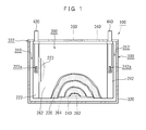
- FIG. 1 is a diagram illustrating an example of the structure of a lithium ion secondary battery.
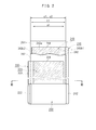
- FIG. 2 is a view showing a wound electrode body of a lithium ion secondary battery.
- FIG. 3 is a cross-sectional view showing a III-III cross section in FIG.
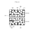
- FIG. 4 is a cross-sectional view showing the structure of the positive electrode active material layer.
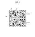
- FIG. 5 is a cross-sectional view showing the structure of the negative electrode active material layer.
- FIG. 6 is a side view showing a welding location between an uncoated portion of the wound electrode body and the electrode terminal.
- FIG. 7 is a diagram schematically illustrating a state of the lithium ion secondary battery during charging.
- FIG. 8 is a diagram schematically showing a state of the lithium ion secondary battery during discharge.
- FIG. 9 is a diagram illustrating a configuration example of an apparatus for obtaining a cyclic voltammogram.
- FIG. 10 is a diagram schematically showing the structure of a lithium ion secondary battery.
- FIG. 11 is a diagram illustrating a process of forming a negative electrode active material layer.
- FIG. 12 is a diagram showing an electrode material coating apparatus.
- FIG. 13 is a diagram schematically showing the structure of a laminate type test battery.
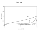
- FIG. 14 is a graph illustrating an example of measurement of the equilibrium potential of the negative electrode active material layer.
- FIG. 15 is a process diagram showing a charge / discharge cycle process in the evaluation test.
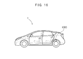
- FIG. 16 is a diagram showing a vehicle equipped with a secondary battery.
- FIG. 1 shows a lithium ion secondary battery 100.
- the lithium ion secondary battery 100 includes a wound electrode body 200 and a battery case 300.
- FIG. 2 is a view showing a wound electrode body 200.
- FIG. 3 shows a III-III cross section in FIG.
- the wound electrode body 200 includes a positive electrode sheet 220, a negative electrode sheet 240, and separators 262 and 264.
- the positive electrode sheet 220, the negative electrode sheet 240, and the separators 262 and 264 are respectively strip-shaped sheet materials.
- the positive electrode sheet 220 has a strip-shaped positive electrode current collector 221 (positive electrode core material).
- a metal foil suitable for the positive electrode can be suitably used.
- a strip-shaped aluminum foil having a predetermined width is used.
- the positive electrode sheet 220 has an uncoated portion 222 and a positive electrode active material layer 223.
- the uncoated part 222 is set along the edge of one side in the width direction of the positive electrode current collector 221.
- the positive electrode active material layer 223 is a layer containing a positive electrode active material.
- the positive electrode active material layer 223 is formed on both surfaces of the positive electrode current collector 221 except for the uncoated portion 222 set on the positive electrode current collector 221.
- FIG. 4 is a cross-sectional view of the positive electrode sheet 220 of the lithium ion secondary battery 100.
- the positive electrode active material 610, the conductive material 620, and the binder 630 in the positive electrode active material layer 223 are schematically illustrated so that the structure of the positive electrode active material layer 223 is clear.
- the positive electrode active material layer 223 includes a positive electrode active material 610, a conductive material 620, and a binder 630.
- the positive electrode active material 610 a material used as a positive electrode active material of a lithium ion secondary battery can be used.
- the positive electrode active material 610 include LiNiCoMnO 2 (lithium nickel cobalt manganese composite oxide), LiNiO 2 (lithium nickelate), LiCoO 2 (lithium cobaltate), LiMn 2 O 4 (lithium manganate), LiFePO 4. And lithium transition metal oxides such as (lithium iron phosphate).
- LiMn 2 O 4 for example, has a spinel structure.
- LiNiO 2 and LiCoO 2 have a layered rock salt structure.
- LiFePO 4 has, for example, an olivine structure.
- LiFePO 4 having an olivine structure includes, for example, nanometer order particles.
- LiFePO 4 having an olivine structure can be further covered with a carbon film.
- the conductive material 620 examples include carbon materials such as carbon powder and carbon fiber. One kind selected from such conductive materials may be used alone, or two or more kinds may be used in combination.
- the carbon powder various carbon blacks (for example, acetylene black, oil furnace black, graphitized carbon black, carbon black, graphite, ketjen black), graphite powder, and the like can be used.
- the binder 630 binds the particles of the positive electrode active material 610 and the conductive material 620, or binds the particles and the positive electrode current collector 221.
- a polymer that can be dissolved or dispersed in a solvent to be used can be used as the binder 630.
- cellulose-based polymers such as carboxymethyl cellulose (CMC) and hydroxypropylmethyl cellulose (HPMC), and also, for example, polyvinyl alcohol (PVA) and polytetrafluoroethylene (PTFE) Rubbers such as fluorine resins such as tetrafluoroethylene-hexafluoropropylene copolymer (FEP), vinyl acetate copolymer, styrene butadiene copolymer (SBR), and acrylic acid-modified SBR resin (SBR latex); A water-soluble or water-dispersible polymer such as can be preferably used.
- CMC carboxymethyl cellulose
- HPMC hydroxypropylmethyl cellulose
- PVA polyvinyl alcohol
- PTFE polytetrafluoroethylene
- FEP tetrafluoroethylene-hexafluoropropylene copolymer
- SBR styrene butadiene copolymer
- SBR latex acrylic acid-mod
- polymers such as polyvinylidene fluoride (PVDF), polyvinylidene chloride (PVDC), and polyacrylonitrile (PAN) can be preferably used.
- PVDF polyvinylidene fluoride
- PVDC polyvinylidene chloride
- PAN polyacrylonitrile
- the polymer material exemplified above may be used for the purpose of exhibiting a function as a thickener or other additive of the composition in addition to the function as a binder.
- the positive electrode active material layer 223 is prepared, for example, by preparing a positive electrode mixture in which the above-described positive electrode active material 610 and the conductive material 620 are mixed in a paste (slurry) with a solvent, applied to the positive electrode current collector 221, and dried. It is formed by rolling.
- a solvent any of an aqueous solvent and a non-aqueous solvent can be used.
- a preferred example of the non-aqueous solvent is N-methyl-2-pyrrolidone (NMP).
- the mass ratio of the positive electrode active material in the total positive electrode mixture is preferably about 50 wt% or more (typically 50 to 95 wt%), and usually about 70 to 95 wt% (for example, 75 to 90 wt%). It is more preferable. Further, the ratio of the conductive material to the whole positive electrode mixture can be, for example, about 2 to 20 wt%, and is usually preferably about 2 to 15 wt%. In the composition using the binder, the ratio of the binder to the whole positive electrode mixture can be, for example, about 1 to 10 wt%, and usually about 2 to 5 wt%.
- the negative electrode sheet 240 has a strip-shaped negative electrode current collector 241 (negative electrode core material).
- a metal foil suitable for the negative electrode can be suitably used.
- a strip-shaped copper foil having a predetermined width is used for the negative electrode current collector 241.
- the negative electrode sheet 240 has an uncoated portion 242 and a negative electrode active material layer 243.
- the uncoated portion 242 is set along the edge on one side in the width direction of the negative electrode current collector 241.
- the negative electrode active material layer 243 is a layer containing a negative electrode active material.
- the negative electrode active material layer 243 is formed on both surfaces of the negative electrode current collector 241 except for the uncoated portion 242 set on the negative electrode current collector 241.
- FIG. 5 is a cross-sectional view of the negative electrode sheet 240 of the lithium ion secondary battery 100.
- the negative electrode active material 710 and the binder 730 in the negative electrode active material layer 243 are schematically illustrated so as to clarify the structure of the negative electrode active material layer 243.
- the negative electrode active material 710 is not limited to the illustrated example.
- the negative electrode active material layer 243 includes a negative electrode active material 710, a thickener (not shown), a binder 730, and the like. The negative electrode active material 710 included in the negative electrode active material layer 243 will be described later.
- the separators 262 and 264 are members that separate the positive electrode sheet 220 and the negative electrode sheet 240.
- the separators 262 and 264 are made of a strip-shaped sheet material having a predetermined width and having a plurality of minute holes.
- Examples of the separators 262 and 264 include a single layer structure separator and a multilayer structure separator made of a porous polyolefin resin.
- the wound electrode body 200 is an electrode body in which the positive electrode sheet 220 and the negative electrode sheet 240 are overlapped and wound while the separators 262 and 264 are interposed between the positive electrode active material layer 223 and the negative electrode active material layer 243. is there.
- the positive electrode sheet 220, the negative electrode sheet 240, and the separators 262 and 264 are aligned in the length direction, and the positive electrode sheet 220, the separator 262, the negative electrode sheet 240, and the separator 264 are aligned. They are stacked in order.
- the separators 262 and 264 are interposed, the negative electrode active material layer 243 is overlaid so as to cover the positive electrode active material layer 223.
- the uncoated part 222 of the positive electrode sheet 220 and the uncoated part 242 of the negative electrode sheet 240 are overlapped so as to protrude on opposite sides in the width direction of the separators 262 and 264.
- the stacked sheet material (for example, the positive electrode sheet 220) is wound around a winding axis set in the width direction.
- the wound electrode body 200 controls the position of each sheet with a position adjusting mechanism such as EPC (edge position control) in the step of winding the positive electrode sheet 220, the negative electrode sheet 240, and the separators 262 and 264. While stacking each sheet.
- EPC edge position control
- the battery case 300 is a so-called square battery case, and includes a container body 320 and a lid 340.
- the container main body 320 has a bottomed rectangular tube shape and is a flat box-shaped container having one side surface (upper surface) opened.
- the lid 340 is a member that is attached to the opening (opening on the upper surface) of the container body 320 and closes the opening.
- the container main body 320 can be molded by, for example, deep drawing molding or impact molding. Impact molding is a kind of cold forging, and is also referred to as impact extrusion or impact press.
- the battery case 300 has a flat rectangular internal space as a space for accommodating the wound electrode body 200.
- the flat internal space of the battery case 300 is slightly wider than the wound electrode body 200.
- the wound electrode body 200 is accommodated in the internal space of the battery case 300.
- the wound electrode body 200 is accommodated in the battery case 300 in a state of being flatly deformed in one direction orthogonal to the winding axis.
- the electrode terminals 420 and 440 are attached to the lid 340 of the battery case 300.
- the electrode terminals 420 and 440 pass through the battery case 300 (lid 340) and come out of the battery case 300.
- the lid 340 is provided with a safety valve 360.
- the wound electrode body 200 is attached to electrode terminals 420 and 440 attached to the battery case 300 (in this example, the lid body 340).
- the wound electrode body 200 is housed in the battery case 300 in a state of being flatly pushed and bent in one direction orthogonal to the winding axis.
- the uncoated part 222 of the positive electrode sheet 220 and the uncoated part 242 of the negative electrode sheet 240 protrude on the opposite sides in the width direction of the separators 262 and 264.
- one electrode terminal 420 is fixed to the uncoated part 222 of the positive electrode current collector 221, and the other electrode terminal 440 is fixed to the uncoated part 242 of the negative electrode current collector 241. .
- the electrode terminals 420 and 440 of the lid 340 extend to the uncoated portion 222 of the wound electrode body 200 and the intermediate portions 224 and 244 of the uncoated portion 242. Yes.
- the tip portions 420a and 440a of the electrode terminals 420 and 440 are welded to respective intermediate portions of the uncoated portions 222 and 242 as shown in FIG.
- FIG. 6 is a side view showing a welding location between the uncoated portions 222 and 242 of the wound electrode body 200 and the electrode terminals 420 and 440.
- the uncoated portion 222 of the positive electrode current collector 221 and the uncoated portion 242 of the negative electrode current collector 241 are exposed in a spiral shape. As shown in FIG. 6, in this embodiment, these uncoated portions 222 and 242 are gathered together at the intermediate portions 224 and 244, respectively, and welded to the tip portions 420a and 440a of the electrode terminals 420 and 440, respectively. .
- ultrasonic welding is used for welding the electrode terminal 420 and the positive electrode current collector 221 due to the difference in materials.
- resistance welding is used for welding the electrode terminal 440 and the negative electrode current collector 241.
- the wound electrode body 200 is attached to the electrode terminals 420 and 440 fixed to the lid body 340 in a state of being flatly pushed and bent.
- the wound electrode body 200 is accommodated in the flat internal space of the container body 320.
- the container body 320 is closed by the lid 340 after the wound electrode body 200 is accommodated.
- the joint 322 (see FIG. 1) between the lid 340 and the container body 320 is welded by, for example, laser welding.
- the wound electrode body 200 is positioned in the battery case 300 by the electrode terminals 420 and 440 fixed to the lid 340 (battery case 300).
- an electrolytic solution is injected into the battery case 300 from a liquid injection hole provided in the lid 340.
- an electrolytic solution in which LiPF 6 is contained at a concentration of about 1 mol / liter in a mixed solvent of ethylene carbonate and diethyl carbonate (for example, a mixed solvent having a volume ratio of about 1: 1) is used. Yes.
- a metal sealing cap is attached to the injection hole (for example, by welding) to seal the battery case 300.
- the nonaqueous electrolyte solution conventionally used for a lithium ion secondary battery can be used.
- the flat internal space of the battery case 300 is slightly wider than the wound electrode body 200 deformed flat.
- gaps 310 and 312 are provided between the wound electrode body 200 and the battery case 300.
- the gaps 310 and 312 serve as a gas escape path.
- the lithium ion secondary battery 100 having such a configuration has a high temperature when overcharge occurs.
- the electrolyte solution is decomposed to generate gas.
- the generated gas is smoothly discharged to the outside through the gaps 310 and 312 between the wound electrode body 200 and the battery case 300 on both sides of the wound electrode body 200 and the safety valve 360.
- the positive electrode current collector 221 and the negative electrode current collector 241 are electrically connected to an external device through electrode terminals 420 and 440 that penetrate the battery case 300.
- the positive electrode mixture is applied to both surfaces of the positive electrode current collector 221.
- the positive electrode mixture layer (positive electrode active material layer 223) includes a positive electrode active material 610 and a conductive material 620.
- the negative electrode mixture is applied to both surfaces of the negative electrode current collector 241.
- the negative electrode mixture layer (negative electrode active material layer 243) contains a negative electrode active material 710.
- the positive electrode active material layer 223 has a minute gap that should also be referred to as a cavity, for example, between the particles of the positive electrode active material 610 and the conductive material 620.
- An electrolytic solution (not shown) can penetrate into the minute gaps of the positive electrode active material layer 223.
- the negative electrode active material layer 243 has minute gaps that should also be referred to as cavities, for example, between the particles of the negative electrode active material 710.
- An electrolyte solution (not shown) can permeate into the minute gaps of the negative electrode active material layer 243.
- a gap cavity
- a hole is appropriately referred to as a “hole”.
- FIG. 7 schematically shows the state of the lithium ion secondary battery 100 during charging.
- the electrode terminals 420 and 440 (see FIG. 1) of the lithium ion secondary battery 100 are connected to the charger 290. Due to the action of the charger 290, lithium ions are released from the positive electrode active material 610 (see FIG. 4) in the positive electrode active material layer 223 to the electrolytic solution 280 during charging. Electrons are emitted from the positive electrode active material 610 (see FIG. 4). The emitted electrons are sent to the positive electrode current collector 221 through the conductive material 620 and further sent to the negative electrode through the charger 290 as shown in FIG. In the negative electrode, electrons are stored, and lithium ions in the electrolytic solution 280 are absorbed and stored in the negative electrode active material 710 (see FIG. 5) in the negative electrode active material layer 243.
- FIG. 8 schematically shows a state of the lithium ion secondary battery 100 during discharging.
- electrons are sent from the negative electrode to the positive electrode, and lithium ions (Li ions) stored in the negative electrode active material layer 243 are released into the electrolytic solution 280.
- lithium ions in the electrolytic solution 280 are taken into the positive electrode active material 610 in the positive electrode active material layer 223.
- lithium ions pass between the positive electrode active material layer 223 and the negative electrode active material layer 243 through the electrolytic solution 280.
- the electrolyte solution 280 penetrates, and required vacancies that allow lithium ions to diffuse smoothly are around the positive electrode active material 610 (see FIG. 4) and the negative electrode active material 710. It is desirable to be around (see FIG. 5). With this configuration, sufficient lithium ions can exist around the positive electrode active material 610 and the negative electrode active material 710. For this reason, the movement of lithium ions between the electrolytic solution 280 and the positive electrode active material 610 and between the electrolytic solution 280 and the negative electrode active material 710 becomes smooth.
- the positive electrode active material 610 is made of a lithium transition metal oxide and has poor conductivity. For this reason, the movement of electrons between the positive electrode active material 610 and the positive electrode current collector 221 is mainly performed through the conductive material 620.
- the negative electrode active material layer 243 of the lithium ion secondary battery 100 will be described in more detail.
- the width b1 of the negative electrode active material layer 243 is slightly wider than the width a1 of the positive electrode active material layer 223.
- the widths c1 and c2 of the separators 262 and 264 are slightly wider than the width b1 of the negative electrode active material layer 243 (c1, c2> b1> a1).
- the positive electrode sheet 220, the negative electrode sheet 240, and the separators 262, 264 are stacked in the order of the positive electrode sheet 220, the separator 262, the negative electrode sheet 240, and the separator 264.
- the separators 262 and 264 are interposed, the negative electrode active material layer 243 covers the positive electrode active material layer 223, and the separators 262 and 264 cover the negative electrode active material layer 243.
- the negative electrode active material layer 243 has a portion 243a facing the positive electrode active material layer 223 and portions 243b1 and 243b2 not facing the positive electrode active material layer 223.
- a portion 243 a facing the positive electrode active material layer 223 is provided in an intermediate portion in the width direction of the negative electrode active material layer 243.
- the portions 243b1 and 243b2 that do not face the positive electrode active material layer 223 are provided in the positive electrode active material layer 223 on both sides in the width direction of the negative electrode active material layer 243.
- the part 243 b 1 not facing the positive electrode active material layer 223 is provided along the uncoated part 242 of the negative electrode sheet 240.
- the part 243b2 that does not face the positive electrode active material layer 223 is provided along the edge of the negative electrode sheet 240 opposite to the uncoated part 242.
- the “equilibrium potential” is a potential indicated when the reaction in which the oxidant is reduced and the reaction in which the reductant is oxidized are balanced on the test electrode immersed in the electrolytic solution. Such an equilibrium potential is also referred to as an electrode potential.
- the negative electrode active material layer 243 includes a portion 243a having a high equilibrium potential and a portion 243b1, 243b2 having a low equilibrium potential.
- the portions 243b1 and 243b2 having a low equilibrium potential in the negative electrode active material layer 243 tend to release lithium ions more easily than the portions 243a having a high equilibrium potential in the negative electrode active material layer 243. is there.
- the portion 243a having a high equilibrium potential in the negative electrode active material layer 243 tends to absorb lithium ions more easily than the portions 243b1 and 243b2 having a low equilibrium potential.
- the parts 243b1 and 243b2 (parts where the equilibrium potential is low) not facing the positive electrode active material layer 223 are parts 243a (parts where the equilibrium potential is high) facing the positive electrode active material layer 223. Rather, it tends to release lithium ions.
- the portion 243 a facing the positive electrode active material layer 223 tends to absorb lithium ions more easily than the portions 243 b 1 and 243 b 2 not facing the positive electrode active material layer 223. For this reason, an event is observed in which lithium ions substantially move from the portions 243b1 and 243b2 that do not face the positive electrode active material layer 223 to the portion 243a that faces the positive electrode active material layer 223.
- the equilibrium potential of the negative electrode active material layer is, for example, a cyclic voltammogram (cyclic voltammogram).
- FIG. 9 shows a configuration example of an apparatus 800 for obtaining such a cyclic voltammogram.
- a test electrode 810 and a reference electrode 820 to be measured are prepared.
- an active material layer 814 to be evaluated is formed on a current collector 812 here.
- the reference electrode 820 an electrode in which a metal lithium 824 is held on a current collector 822 is used.
- a cell is prepared in which an active material layer 814 to be evaluated is opposed to a reference electrode 820 with a separator 830 interposed therebetween and immersed in an electrolytic solution.
- the test electrode 810 and the reference electrode 820 are connected to a measuring device 840 that applies a predetermined potential difference between the test electrode 810 and the reference electrode 820 and obtains a cyclic voltammogram. Then, the average value of the voltage value of the SOC-voltage characteristic at the time of charging with a low current (for example, 1/10 C) and the SOC-voltage characteristic at the time of discharging under the same condition may be set as the equilibrium potential.
- the current collector 812 of the test electrode 810 is made of the same material as the negative electrode current collector 241 used for the negative electrode sheet 240.
- the active material layer 814 of the test electrode 810 includes a portion 243 a of the negative electrode active material layer 243 that faces the positive electrode active material layer 223 and a portion 243 b 1 and 243 b 2 that does not face the positive electrode active material layer 223. The active material layer is reproduced.
- an electrode 810 to be measured an electrode having an active material layer similar to the portion 243 a facing the positive electrode active material layer 223 on the active material layer 814, or facing the positive electrode active material layer 223 is used.
- the electrode which has the active material layer similar to the part 243b1, 243b2 which does not exist is prepared.
- an equilibrium potential is obtained for each test electrode 810 based on the cyclic voltammogram. Based on the equilibrium potential of each test electrode, the equilibrium potential Ea of the part 243a facing the positive electrode active material layer 223 and the equilibrium potential Eb of the parts 243b1 and 243b2 not facing the positive electrode active material layer 223 are estimated. Good.
- the equilibrium potential varies depending on the state of charge of the cell.
- the equilibrium potential may be estimated in consideration of a state of charge (SOC) state in which the lithium ion secondary battery 100 is normally used.
- the cyclic voltammogram may be obtained in consideration of a potential range that acts on the negative electrode active material layer 243 in a state in which the lithium ion secondary battery 100 is normally used.
- the potential applied to the cell when obtaining the cyclic voltammogram may be determined in consideration of the potential range that acts on the negative electrode active material layer 243 in a state in which the lithium ion secondary battery 100 is normally used.
- the equilibrium potential of the part 243a facing the positive electrode active material layer 223 and the equilibrium potential of the parts 243b1 and 243b2 not facing the positive electrode active material layer 223 may be estimated.
- the equilibrium potential Ea of the portion 243a facing the positive electrode active material layer 223 faces the positive electrode active material layer 223. It is good that it is higher (Ea> Eb) than the equilibrium potential Eb of the parts 243b1, 243b2 that are not present. Thereby, it can prevent more reliably that lithium ion fixes to the site
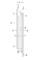
- FIG. 10 schematically shows the structure of the lithium ion secondary battery 100.
- FIG. 10 shows a cross section in which the negative electrode active material layer 243 and the positive electrode active material layer 223 in the wound electrode body 200 (see FIG. 1) are cut in the width direction (for example, the width direction of the positive electrode sheet 220).
- the positive electrode active material layer 223 formed on one surface of the positive electrode current collector 221 is shown as the positive electrode active material layer 223.
- the negative electrode active material layer 243 formed on one surface of the negative electrode current collector 241 is shown as the negative electrode active material layer 243.
- the separators 262 and 264 are simply indicated by broken lines.
- the intermediate portion in the width direction of the negative electrode active material layer 243 faces the positive electrode active material layer 223, but both sides of the negative electrode active material layer 243 in the width direction are on the positive electrode active material layer. 223 is not opposed.
- the widths of the portions 243b1 and 243b2 that do not face the positive electrode active material layer 223 are illustrated to be larger than actual.
- the equilibrium potential Ea of the part 243a facing the positive electrode active material layer 223 in the negative electrode active material layer 243 is higher than the equilibrium potential Eb of the parts 243b1 and 243b2 not facing the positive electrode active material layer 223.
- the parts 243b1 and 243b2 parts having a low equilibrium potential
- the parts 243a and 243b2 are more lithium than the parts 243a (parts having a high equilibrium potential) that face the positive electrode active material layer 223.
- the portion 243 a facing the positive electrode active material layer 223 tends to absorb lithium ions more easily than the portions 243 b 1 and 243 b 2 not facing the positive electrode active material layer 223. In addition, for this reason, an event is observed in which lithium ions substantially move from the portions 243b1 and 243b2 that do not face the positive electrode active material layer 223 to the portion 243a that faces the positive electrode active material layer 223.
- the equilibrium potential Ea of the portion 243a facing the positive electrode active material layer 223 has a portion 243b1 not facing the positive electrode active material layer 223, It is higher than the equilibrium potential Eb of 243b2 (Ea> Eb).
- lithium ions occluded in the portions 243b1 and 243b2 of the negative electrode active material layer 243 that do not face the positive electrode active material layer 223 are fixed to the portions 243b1 and 243b2 that do not face the positive electrode active material layer 223. There is no. Thereby, the lithium ions occluded in the portions 243b1 and 243b2 that are not opposed to the positive electrode active material layer 223 are utilized in the subsequent reaction of the battery, and the battery capacity can be suppressed from decreasing.
- the lithium ion secondary battery 100 can more reliably prevent lithium ions from being fixed to the portions 243b1 and 243b2 that are not opposed to the positive electrode active material layer 223, particularly even in applications where charging and discharging are repeated. For this reason, the lithium ion secondary battery 100 can suppress the battery capacity from decreasing further even in applications where the battery is repeatedly charged and discharged.
- the positive electrode current collector 221 and the negative electrode current collector 241 are each in the form of a strip.
- the positive electrode active material layer 223 is held on the positive electrode current collector 221 with a predetermined area.
- the negative electrode active material layer 243 is held by the positive electrode current collector 221 in an area larger than that of the positive electrode active material layer 223.
- the negative electrode active material layer 243 covers the positive electrode active material layer 223. Therefore, the negative electrode active material layer 243 includes portions 243b1 and 243b2 that do not face the positive electrode active material layer 223.
- the portions 243b1 and 243b2 that do not face the positive electrode active material layer 223 can more reliably capture lithium ions released from the positive electrode active material layer 223. For this reason, it can prevent more reliably that lithium precipitates in the lithium ion secondary battery 100. Further, the equilibrium potential Eb of the parts 243b1 and 243b2 not facing the positive electrode active material layer 223 is lower than the equilibrium potential Ea of the part 243a facing the positive electrode active material layer 223 (Ea> Eb). For this reason, in the lithium ion secondary battery 100, although the negative electrode active material layer 243 includes the portions 243b1 and 243b2 that do not face the positive electrode active material layer 223, lithium ions are not easily fixed to the portions 243b1 and 243b2. Battery capacity is unlikely to decrease.
- the negative electrode active material layer 243 uses different negative electrode active materials for the portion 243a facing the positive electrode active material layer 223 and the portions 243b1 and 243b2 not facing the positive electrode active material layer 223. ing. As a result, a difference between the equilibrium potential Ea of the portion 243a of the negative electrode active material layer 243 that faces the positive electrode active material layer 223 and the balance potential Eb of the portions 243b1 and 243b2 that do not face the positive electrode active material layer 223. Is attached.
- the negative electrode active material used in the portions 243b1 and 243b2 that do not face the positive electrode active material layer 223 and the portion 243a that faces the positive electrode active material layer 223 is completely used. It may be difficult to make them different.
- the negative electrode active material layer 243 includes a negative electrode active material that contributes to a relatively high equilibrium potential and a negative electrode active material that contributes to a relatively low equilibrium potential. Yes.
- the proportion of the negative electrode active material contributing to the increase in the equilibrium potential Ea is higher than in the portions 243b1 and 243b2 not facing the positive electrode active material layer 223. Good.
- the proportion of the negative electrode active material contributing to the decrease in the equilibrium potential Ea is higher than in the parts 243b1 and 243b2 not facing the positive electrode active material layer 223. Low is good.
- the weight ratio of the negative electrode active material contributing to the increase in the equilibrium potential Ea is 70 wt% or more (more preferably 80 wt% or more, further preferably Is preferably 90 wt% or more.
- the weight ratio of the negative electrode active material that contributes to lowering the equilibrium potential Ea is 70 wt% or more (more preferably 80 wt% or more, More preferably, it is 90 wt% or more.
- the equilibrium potential Ea of the part 243a facing the positive electrode active material layer 223 is equal to the part 243a facing the positive electrode active material layer 223 and the parts 243b1 and 243b2 not facing the positive electrode active material layer 223. It is good to evaluate in the site
- Negative Electrode Active Material Included in Negative Electrode Active Material Layer 243 >>
- the negative electrode active material of the lithium ion secondary battery 100 for example, graphite (carbon-based material) such as natural graphite, artificial graphite, natural graphite, or amorphous carbon of artificial graphite can be used.
- graphite has different equilibrium potentials of the negative electrode active material layer depending on the type.
- graphite that contributes to changing the equilibrium potential of the negative electrode active material layer includes graphitizable carbon (soft carbon), non-graphitizable carbon (hard carbon), and graphitic material (graphite).
- the graphitizable carbon is a carbonaceous material that is easily graphitized.
- Examples of graphitizable carbon include carbon materials obtained by heat treating coke in a high temperature atmosphere of about 1000 ° C. to 2000 ° C. Such a carbon material has a low mechanical strength and is also referred to as “soft carbon”.
- Non-graphitizable carbon is a carbonaceous material that is difficult to graphitize.
- non-graphitizable carbon fine graphite crystals are arranged in random directions, and there are pores with a size of several nanometers between the crystals.
- Non-graphitizable carbon is obtained, for example, by carbonizing a thermosetting resin. The non-graphitizable carbon obtained by carbonizing the thermosetting resin does not develop a graphite structure even when the heat treatment temperature is increased.
- the non-graphitizable carbon as the negative electrode active material is, for example, a phenol resin fired body, a furfuryl alcohol resin fired body, a polyacrylonitrile (PAN) carbon fiber, pseudo-isotropic carbon, coffee bean And fired natural materials such as sugar.
- PAN polyacrylonitrile
- Such a carbon material is also called “hard carbon” because it has higher mechanical strength than the above-mentioned soft carbon.
- the graphite material is a carbon material that has been graphitized.
- Examples of the graphite material include a carbon material obtained by heat-treating coke in a high-temperature atmosphere of 2000 ° C. or higher (for example, about 2800 ° C.).
- the equilibrium of the negative electrode active material layer 243 is higher than when non-graphitizable carbon or graphitic material is used as the negative electrode active material.
- the potential increases.
- the equilibrium potential of the negative electrode active material layer 243 is higher than when a graphitic material is used for the negative electrode active material.
- the equilibrium potential in the state of charge (SOC) in which the lithium ion secondary battery 100 is normally used is important.
- the equilibrium potential is preferably evaluated in a range of a charged state where the secondary battery can be repeatedly charged and discharged.
- the equilibrium potentials of the negative electrode active material layer are respectively compared.
- the equilibrium potential of the negative electrode active material layer is determined to be graphitizable carbon.
- non-graphitizable carbon hard carbon
- the negative electrode active material layer 243 is used.
- a graphite material may be used as the negative electrode active material.
- the negative electrode active material layer 243 facing the positive electrode active material layer 223 when graphitizable carbon (soft carbon) is used as the negative electrode active material, the negative electrode active material layer 243 In the portions 243b1 and 243b2 that do not face the positive electrode active material layer 223, non-graphitizable carbon or a graphitic material is preferably used as the negative electrode active material. Accordingly, the portion 243a of the negative electrode active material layer 243 facing the positive electrode active material layer 223 exhibits a higher equilibrium potential than the portions 243b1 and 243b2 not facing the positive electrode active material layer 223.
- FIG. 11 is a diagram illustrating a process in which the negative electrode active material layer 243 is formed.
- the negative electrode active material layer 243 is formed by applying a mixture containing a negative electrode active material to the negative electrode current collector 241 with a predetermined width, drying, and rolling.
- a running path 12 for running the negative electrode current collector 241 and a mixture that forms the negative electrode active material layer 243 on the negative electrode current collector 241 are provided.
- a coating device 14 for coating and a drying furnace 16 for drying the mixture coated on the negative electrode current collector 241 are provided.
- the travel route 12 is a route for causing the negative electrode current collector 241 to travel.
- a plurality of guides 12 b are arranged on the traveling route 12 along a predetermined route for traveling the negative electrode current collector 241.
- a supply unit 32 that supplies the negative electrode current collector 241 is provided at the start end of the traveling path 12.
- a negative electrode current collector 241 wound around a winding core 32a in advance is disposed.
- An appropriate amount of the negative electrode current collector 241 is appropriately supplied from the supply unit 32 to the travel path 12.
- a collection unit 34 that collects the negative electrode current collector 241 is provided at the end of the traveling path 12. The collection unit 34 winds the negative electrode current collector 241 that has been subjected to a predetermined process in the travel path 12 around the winding core 34a.
- the collection unit 34 is provided with, for example, a control unit 34b and a motor 34c.
- the control unit 34b is preset with a program for controlling the rotation of the winding core 34a of the collection unit 34.
- the motor 34c is an actuator that rotationally drives the winding core 34a, and is driven according to a program set in the control unit 34b.
- An electrode material coating device 14 and a drying furnace 16 are sequentially arranged on the traveling path 12.
- the negative electrode active material layer includes a portion 243 a that faces the positive electrode active material layer 223 and portions 243 b 1 and 243 b 2 that do not face the positive electrode active material layer 223.
- the negative electrode active materials included in H.243 are different.
- the electrode material coating apparatus 14 applies a mixture containing different negative electrode active materials at the portion 243a facing the positive electrode active material layer 223 and the portions 243b1 and 243b2 not facing the positive electrode active material layer 223.
- the electrode material application device 14 includes flow paths 41 and 42, filters 43 and 44, and an application unit 45.
- the electrode material application device 14 is configured to apply the mixture to the negative electrode current collector 241 that travels on the back roll 46 disposed in the travel path 12.
- the electrode material coating apparatus 14 further includes tanks 47 and 48 and pumps 49 and 50.
- the tanks 47 and 48 are containers storing different mixtures.
- the pumps 49 and 50 are devices that send the mixture from the tanks 47 and 48 to the flow paths 41 and 42, respectively.
- the channels 41 and 42 are channels through which a slurry in which a negative electrode active material is dispersed in a solvent can flow.
- the flow paths 41 and 42 reach the application unit 45 from the tanks 47 and 48, respectively.
- the filters 43 and 44 are disposed in the flow paths 41 and 42.
- a first mixture used to form a negative electrode active material layer having a relatively high equilibrium potential and a negative electrode active material layer having a relatively low equilibrium potential are formed in the tanks 47 and 48.
- a second mixture used for the preparation As described above, the first mixture and the second mixture are different in the type of the negative electrode active material contained in the solvent.
- the application unit 45 applies a first mixture containing a negative electrode active material having a high equilibrium potential to the portion 243 a facing the positive electrode active material layer 223 to the negative electrode current collector 241.
- the application unit 45 applies a second mixture containing a negative electrode active material having a low equilibrium potential to the portions 243b1 and 243b2 that do not face the positive electrode active material layer 223.
- a die 60 having a horizontally long discharge port 62 is used for the application unit 45.
- the discharge port 62 of the die 60 is divided into an intermediate portion 62a and both side portions 62b1 and 62b2.
- a flow path is formed which is continuous with the intermediate portion 62a and both side portions 62b1 and 62b2.
- An intermediate portion 62a of the discharge port 62 communicates with the flow path 41 to which the first mixture is supplied. Further, both side portions 62b1 and 62b2 of the discharge port 62 communicate with the flow path 42 to which the second mixture is supplied.
- the first mixture is a mixture used to form a negative electrode active material layer having a relatively high equilibrium potential.
- the second mixture is a mixture used to form a negative electrode active material layer having a relatively low equilibrium potential. Therefore, the intermediate portion 62a of the discharge port 62 discharges the first mixture used to form the negative electrode active material layer having a relatively high equilibrium potential. Further, both side portions 62b1 and 62b2 of the discharge port 62 discharge a second mixture used to form a negative electrode active material layer having a relatively low equilibrium potential.
- the die 60 is arranged with the intermediate portion 62a of the discharge port 62 aligned with the part 243a so that the first mixture is applied to the part 243a facing the positive electrode active material layer 223.
- both sides 62b1 and 62b2 of the discharge port 62 are aligned with the portions 243b1 and 243b2 so that the second mixture is applied to the portions 243b1 and 243b2 that are not opposed to the positive electrode active material layer 223.
- the first mixture can be applied to the part 243a facing the positive electrode active material layer 223, and the second mixture can be applied to the parts 243b1 and 243b2 not facing the positive electrode active material layer 223.
- the first mixture is applied to the part 243a facing the positive electrode active material layer 223, and the second mixture is applied to the parts 243b1 and 243b2 not facing the positive electrode active material layer 223.
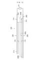
- the current collector 241 is supplied to the drying furnace 16 (see FIG. 11).
- the electrode material application device 14 includes a plurality of partitioned outlets 62a, 62b1, 62b2, and a plurality of flow paths 41, 42 for supplying a mixture to the plurality of outlets 62a, 62b1, 62b2, respectively. It is good to have.
- FIG. 13 shows a laminate type test battery 100A used in such a test.
- the test battery 100A includes a positive electrode sheet 220A having a positive electrode active material layer 223A formed on one side of the positive electrode current collector 221A, and a negative electrode sheet 240A having a negative electrode active material layer 243A formed on one side of the negative electrode current collector 241A. ing.
- the negative electrode active material layer 243A has a larger area than the positive electrode active material layer 223A.
- the negative electrode active material layer 243A faces the positive electrode active material layer 223A, although the separator 262A is interposed.
- the positive electrode current collector 221A and the negative electrode current collector 241A include uncoated portions 222A and 242A, respectively.
- the positive electrode current collector 221A and the negative electrode current collector 241A are connected to the measuring device 270 through the uncoated portions 222A and 242A.
- the positive electrode sheet 220A is, LiFePO 4 is used as the positive electrode active material contained in the positive electrode active material layer 223.
- Acetylene black (AB) was used as the conductive material, and PVDF was used as the binder.
- LiFePO 4 , AB, and PVDF are used as a mixture for forming the positive electrode active material layer 223A.
- NMP is dispersed.
- a mixture prepared as a solvent was prepared. And this mixture was apply
- Electrolyte a porous film made of a composite material of polypropylene and polyethylene is used for the separator 262A. Moreover, the electrolyte solution which mix
- the negative electrode sheet 240A includes a plurality of samples in which negative electrode active materials included in a portion 243A1 of the negative electrode active material layer 243A facing the positive electrode active material layer 223A and a portion 243A2 not facing the positive electrode active material layer 223A are changed. (For example, samples 1 to 7 in Table 1) were formed.
- styrene butadiene copolymer SBR
- carboxymethyl cellulose CMC
- water was used as a solvent.
- a plurality of types of carbon materials suitable for the negative electrode active material were prepared.
- a carbon material, a binder (SBR), and a thickener (CMC) as a negative electrode active material were mixed in water as a solvent in a predetermined weight ratio.
- this mixture was apply
- the negative electrode active material layer 243A includes a portion 243A1 facing the positive electrode active material layer 223A and a portion 243A2 of the negative electrode active material layer 243A that does not face the positive electrode active material layer 223A.
- the material is different.
- Samples 1 to 7 have the same configuration except for the negative electrode active material contained in the portions 243A1 and 243A2.
- Both active materials are graphite materials (graphite-based carbon materials).
- the negative electrode active material contained in the portion 243A1 of the negative electrode active material layer 243A facing the positive electrode active material layer 223A is a graphite material. Further, the negative electrode active material contained in the portion 243A2 of the negative electrode active material layer 243A that does not face the positive electrode active material layer 223A is non-graphitizable carbon.
- the equilibrium potential Ea of the portion 243A1 facing the positive electrode active material layer 223A of the negative electrode active material layer 243A is lower than the equilibrium potential Eb of the portion 243A2 not facing the positive electrode active material layer 223A (Eb > Ea).
- the negative electrode active material contained in the portion 243A1 facing the positive electrode active material layer 223A in the negative electrode active material layer 243A is graphitizable carbon.
- the negative electrode active material included in the portion 243A2 of the negative electrode active material layer 243A that does not face the positive electrode active material layer 223A is a graphite material.
- the equilibrium potential Ea of the part 243A1 of the negative electrode active material layer 243A facing the positive electrode active material layer 223A is equal to the equilibrium potential of the part 243A2 of the negative electrode active material layer 243A not facing the positive electrode active material layer 223A. Higher than Eb (Ea> Eb).
- the negative electrode active material contained in the portion 243A1 facing the positive electrode active material layer 223A is non-graphitizable carbon. Further, the negative electrode active material included in the portion 243A2 of the negative electrode active material layer 243A that does not face the positive electrode active material layer 223A is a graphite material.
- the equilibrium potential Ea of the portion 243A1 facing the positive electrode active material layer 223A of the negative electrode active material layer 243A is equal to the equilibrium potential of the portion 243A2 of the negative electrode active material layer 243A not facing the positive electrode active material layer 223A. Higher than Eb (Ea> Eb).
- the negative electrode active material contained in the portion 243A1 facing the positive electrode active material layer 223A is graphitizable carbon. Further, the negative electrode active material included in the portion 243A2 of the negative electrode active material layer 243A that does not face the positive electrode active material layer 223A is non-graphitizable carbon.
- the equilibrium potential Ea of the portion 243A1 facing the positive electrode active material layer 223A of the negative electrode active material layer 243A is higher than the equilibrium potential Eb of the portion 243A2 not facing the positive electrode active material layer 223A (Ea > Eb).
- FIG. 14 shows an equilibrium potential v1 of a negative electrode active material layer using a graphite material as a negative electrode active material, an equilibrium potential v2 of a negative electrode active material layer using non-graphitizable carbon as a negative electrode active material, and The equilibrium potential v3 of the negative electrode active material layer in which graphitizable carbon is used as the negative electrode active material is shown.
- metallic lithium is used for the reference electrode, the charged state is shown on the horizontal axis, and the equilibrium potential is shown on the vertical axis.
- the method for measuring the equilibrium potential here is in accordance with the example shown in FIG.
- the graphitizable carbon, the non-graphitizable carbon, and the graphite material used here a material that causes a difference of 0.1 V or more in the equilibrium potential of the negative electrode active material layer in the same charged state was selectively used. .
- test batteries of Samples 1 to 7 were charged and discharged at a constant current as an initial process (conditioning process). After that, the battery was charged with a constant current up to a charge upper limit voltage (for example, 4.1 V) at a current value (for example, 100 mA when the estimated battery capacity was 300 mAh) from the theoretical capacity of the positive electrode. . Further, charging was performed at a constant voltage until the final current value became 1/10 of the initial current value.
- a charge upper limit voltage for example, 4.1 V
- a current value for example, 100 mA when the estimated battery capacity was 300 mAh
- FIG. 15 is a diagram showing a process of measuring the cell capacity in the evaluation test.
- discharging and charging were repeated three times at a current value (100 mA) of 1/3 of the battery capacity predicted from the positive electrode theoretical capacity.
- the upper limit voltage during charging was 4.1 V
- the lower limit voltage during discharging was 2.5 V.
- the capacity of the fourth discharge was taken as the initial cell capacity.
- the test battery is placed in a constant temperature bath at 60 ° C. and charged and discharged at a current value three times the battery capacity predicted from the theoretical capacity of the positive electrode (for example, 900 mA if the predicted battery capacity is 300 mAh). Repeated 1000 times. Here, the 1000th time is finished in a charged state. Thereafter, as shown in FIG. 15, the discharge and charge were repeated three times at a current value of 1/3 of the battery capacity predicted from the theoretical capacity of the positive electrode, and the capacity of the fourth discharge was defined as the post-deterioration cell capacity. Then, the capacity retention rate (%) was obtained by dividing the cell capacity after degradation by the initial cell capacity.
- the equilibrium potential Ea of the part 243A1 facing the positive electrode active material layer 223A is higher than the equilibrium potential Eb of the part 243A2 not facing the positive electrode active material layer 223A (Ea> Eb).
- the capacity retention rate of the ion secondary battery 100 is improved.
- the difference between the equilibrium potential Ea of the part 243A1 facing the positive electrode active material layer 223A and the equilibrium potential Eb of the part 243A2 not facing the positive electrode active material layer 223A is 0. If there is a difference of 1 V or more, the effect can be obtained more remarkably.
- the secondary battery according to the embodiment of the present invention has been described above.
- the secondary battery according to the present invention is not limited to the above-described embodiment.
- the present invention is not limited to any of the above-described embodiments unless otherwise specified.
- a cylindrical battery is a battery in which a wound electrode body is accommodated in a cylindrical battery case.
- a laminate type battery is a battery in which a positive electrode sheet and a negative electrode sheet are stacked with a separator interposed therebetween.
- the present invention can contribute to an improvement in the capacity maintenance rate of a secondary battery (for example, a lithium ion secondary battery).
- a secondary battery for example, a lithium ion secondary battery
- the present invention is suitable for lithium ion secondary batteries for vehicle drive power sources such as hybrid vehicles and electric vehicle drive batteries, which require a particularly high level of capacity maintenance ratio over time. is there. That is, the lithium ion secondary battery can be suitably used as a battery 1000 for driving a motor (electric motor) of a vehicle 1 such as an automobile as shown in FIG.
- the vehicle driving battery 1000 may be an assembled battery in which a plurality of secondary batteries are combined.
Landscapes
- Chemical & Material Sciences (AREA)
- Engineering & Computer Science (AREA)
- Chemical Kinetics & Catalysis (AREA)
- Electrochemistry (AREA)
- General Chemical & Material Sciences (AREA)
- Manufacturing & Machinery (AREA)
- Materials Engineering (AREA)
- Secondary Cells (AREA)
- Battery Electrode And Active Subsutance (AREA)
Abstract
Description
正極シート220は、図2に示すように、帯状の正極集電体221(正極芯材)を有している。正極集電体221には、例えば、正極に適する金属箔が好適に使用され得る。この正極集電体221には、所定の幅を有する帯状のアルミニウム箔が用いられている。また、正極シート220は、未塗工部222と正極活物質層223とを有している。未塗工部222は正極集電体221の幅方向片側の縁部に沿って設定されている。正極活物質層223は、正極活物質を含む層である。正極活物質層223は、正極集電体221に設定された未塗工部222を除いて、正極集電体221の両面に形成されている。
ここで、図4は、リチウムイオン二次電池100の正極シート220の断面図である。なお、図4において、正極活物質層223の構造が明確になるように、正極活物質層223中の正極活物質610と導電材620とバインダ630とを大きく模式的に表している。正極活物質層223には、図4に示すように、正極活物質610や導電材620やバインダ630が含まれている。
導電材620としては、例えば、カーボン粉末やカーボンファイバーなどのカーボン材料が例示される。このような導電材から選択される一種を単独で用いてもよく二種以上を併用してもよい。カーボン粉末としては、種々のカーボンブラック(例えば、アセチレンブラック、オイルファーネスブラック、黒鉛化カーボンブラック、カーボンブラック、黒鉛、ケッチェンブラック)、グラファイト粉末などのカーボン粉末を用いることができる。
また、バインダ630は、正極活物質610や導電材620の各粒子を結着させたり、これらの各粒子と正極集電体221とを結着させたりする。かかるバインダ630としては、使用する溶媒に溶解または分散可能なポリマーを用いることができる。例えば、水性溶媒を用いた正極合剤組成物においては、カルボキシメチルセルロース(CMC)、ヒドロキシプロピルメチルセルロース(HPMC)などのセルロース系ポリマー、また例えば、ポリビニルアルコール(PVA)や、ポリテトラフルオロエチレン(PTFE)、テトラフルオロエチレン-ヘキサフルオロプロピレン共重合体(FEP)などのフッ素系樹脂、酢酸ビニル共重合体やスチレンブタジエン共重合体(SBR)、アクリル酸変性SBR樹脂(SBR系ラテックス)などのゴム類;などの水溶性または水分散性ポリマーを好ましく採用することができる。また、非水溶媒を用いた正極合剤組成物においては、ポリフッ化ビニリデン(PVDF)、ポリ塩化ビニリデン(PVDC)、ポリアクリルニトリル(PAN)などのポリマーを好ましく採用することができる。上記で例示したポリマー材料は、バインダとしての機能の他に、上記組成物の増粘剤その他の添加剤としての機能を発揮する目的で使用されることもあり得る。
正極活物質層223は、例えば、上述した正極活物質610や導電材620を溶媒にペースト状(スラリ状)に混ぜ合わせた正極合剤を作成し、正極集電体221に塗布し、乾燥させ、圧延することによって形成されている。この際、溶媒としては、水性溶媒および非水溶媒の何れも使用可能である。非水溶媒の好適な例としてN-メチル-2-ピロリドン(NMP)が挙げられる。
負極シート240は、図2に示すように、帯状の負極集電体241(負極芯材)を有している。負極集電体241には、例えば、負極に適する金属箔が好適に使用され得る。この実施形態では、負極集電体241には、所定の幅を有する帯状の銅箔が用いられている。また、負極シート240は、未塗工部242と、負極活物質層243とを有している。未塗工部242は負極集電体241の幅方向片側の縁部に沿って設定されている。負極活物質層243は、負極活物質を含む層である。負極活物質層243は、負極集電体241に設定された未塗工部242を除いて、負極集電体241の両面に形成されている。
図5は、リチウムイオン二次電池100の負極シート240の断面図である。また、図5において、負極活物質層243の構造が明確になるように、負極活物質層243中の負極活物質710とバインダ730を大きく模式的に表している。ここでは、負極活物質710は、いわゆる鱗片状(Flake Graphite)黒鉛が用いられた場合を図示しているが、負極活物質710は、図示例に限定されない。負極活物質層243には、図5に示すように、負極活物質710や増粘剤(図示省略)やバインダ730などが含まれている。負極活物質層243に含まれる負極活物質710については後で述べる。
セパレータ262、264は、正極シート220と負極シート240とを隔てる部材である。この例では、セパレータ262、264は、微小な孔を複数有する所定幅の帯状のシート材で構成されている。セパレータ262、264には、例えば、多孔質ポリオレフィン系樹脂で構成された単層構造のセパレータや積層構造のセパレータがある。
捲回電極体200は、正極活物質層223と負極活物質層243との間にセパレータ262、264を介在させつつ、正極シート220と負極シート240とを重ね、かつ、捲回した電極体である。この実施形態では、図2および図3に示すように、正極シート220と負極シート240とセパレータ262、264は、長さ方向を揃えて、正極シート220、セパレータ262、負極シート240、セパレータ264の順で重ねられている。この実施形態では、セパレータ262、264が介在した状態ではあるが、負極活物質層243は正極活物質層223を覆うように重ねられている。
また、この例では、電池ケース300は、図1に示すように、いわゆる角型の電池ケースであり、容器本体320と、蓋体340とを備えている。容器本体320は、有底四角筒状を有しており、一側面(上面)が開口した扁平な箱型の容器である。蓋体340は、当該容器本体320の開口(上面の開口)に取り付けられて当該開口を塞ぐ部材である。ここで、容器本体320は、例えば、深絞り成形やインパクト成形によって成形することができる。なお、インパクト成形は、冷間での鍛造の一種であり、衝撃押出加工やインパクトプレスとも称される。
その後、蓋体340に設けられた注液孔から電池ケース300内に電解液が注入される。電解液は、この例では、エチレンカーボネートとジエチルカーボネートとの混合溶媒(例えば、体積比1:1程度の混合溶媒)にLiPF6を約1mol/リットルの濃度で含有させた電解液が用いられている。その後、注液孔に金属製の封止キャップを取り付けて(例えば溶接して)電池ケース300を封止する。なお、電解液としては、従来からリチウムイオン二次電池に用いられる非水電解液を使用することができる。
また、この例では、当該電池ケース300の扁平な内部空間は、扁平に変形した捲回電極体200よりも少し広い。捲回電極体200の両側には、捲回電極体200と電池ケース300との間に隙間310、312が設けられている。当該隙間310、312は、ガス抜け経路になる。
図4に示すように、この実施形態では、正極集電体221の両面にそれぞれ正極合剤が塗工されている。かかる正極合剤の層(正極活物質層223)には、正極活物質610と導電材620が含まれている。図5に示すように、負極集電体241の両面にそれぞれ負極合剤が塗工されている。かかる負極合剤の層(負極活物質層243)には、負極活物質710が含まれている。
また、この実施形態では、正極活物質層223は、例えば、正極活物質610と導電材620の粒子間などに、空洞とも称すべき微小な隙間を有している。かかる正極活物質層223の微小な隙間には電解液(図示省略)が浸み渡り得る。また、負極活物質層243は、例えば、負極活物質710の粒子間などに、空洞とも称すべき微小な隙間を有している。かかる負極活物質層243の微小な隙間には電解液(図示省略)が浸み渡り得る。ここでは、かかる隙間(空洞)を適宜に「空孔」と称する。
図7は、かかるリチウムイオン二次電池100の充電時の状態を模式的に示している。充電時においては、図7に示すように、リチウムイオン二次電池100の電極端子420、440(図1参照)は、充電器290に接続される。充電器290の作用によって、充電時には、正極活物質層223中の正極活物質610(図4参照)からリチウムイオンが電解液280に放出される。また、正極活物質610(図4参照)からは電子が放出される。放出された電子は、図7に示すように、導電材620を通じて正極集電体221に送られ、さらに充電器290を通じて負極へ送られる。また、負極では電子が蓄えられるとともに、電解液280中のリチウムイオンが、負極活物質層243中の負極活物質710(図5参照)に吸収され、かつ、貯蔵される。
図8は、かかるリチウムイオン二次電池100の放電時の状態を模式的に示している。放電時には、図8に示すように、負極から正極に電子が送られるとともに、負極活物質層243に貯蔵されたリチウムイオン(Liイオン)が、電解液280に放出される。また、正極では、正極活物質層223中の正極活物質610に電解液280中のリチウムイオンが取り込まれる。
この実施形態では、負極活物質層243は、正極活物質層223に対向している部位243aの平衡電位Eaが、正極活物質層223に対向していない部位243b1、243b2の平衡電位Ebよりも高い(Ea>Eb)。
ここで、「平衡電位」は、電解液中に浸された試験電極上において酸化体が還元される反応と還元体が酸化される反応とが平衡しているときに示される電位である。かかる平衡電位(equilibrium potential)は、電極電位とも称される。
なお、負極活物質層の平衡電位は、例えば、サイクリックボルタモグラム(cyclic
voltammogram)で求めることができる。図9は、かかるサイクリックボルタモグラムを得る装置800の構成例を示している。かかるサイクリックボルタモグラムを得るには、例えば、図9に示すように、測定対象となる試験用電極810と、基準電極820を用意する。試験用電極810は、ここでは、集電体812に、評価対象となる活物質層814が形成されている。また、基準電極820は、集電体822に、金属リチウム824を保持させた電極が用いられている。
このように正極活物質層223に対向している部位243aと、正極活物質層223に対向していない部位243b1、243b2とで、異なる負極活物質を用いることによって、平衡電位に差が生じる。リチウムイオン二次電池100の負極活物質には、例えば、天然黒鉛、人造黒鉛、天然黒鉛や人造黒鉛のアモルファスカーボンなどの黒鉛(炭素系材料)を用いることができる。かかる黒鉛は、種類によって負極活物質層の平衡電位が異なる。例えば、負極活物質層の平衡電位を異ならせるのに寄与する黒鉛として、易黒鉛化性炭素(soft carbon)や、難黒鉛化性炭素(hard carbon)や、黒鉛質材料(graphite)がある。
ここでは、易黒鉛化性炭素は、黒鉛化が進行し易い炭素質材料である。易黒鉛化性炭素には、例えば、コークスを1000℃~2000℃程度の高温雰囲気で熱処理した炭素材料が挙げられる。かかる炭素材料は、機械強度が低く「ソフトカーボン」とも称される。
難黒鉛化性炭素は、黒鉛化が進み難い炭素質材料である。難黒鉛化性炭素は、微小な黒鉛の結晶がランダムな方向に配置されており、結晶と結晶の間に数nm程度の大きさの空孔がある。難黒鉛化性炭素は、例えば、熱硬化性樹脂を炭素化することによって得られる。熱硬化性樹脂を炭素化した難黒鉛化性炭素は、熱処理温度を高くしても黒鉛構造は発達しない。負極活物質としての難黒鉛化性炭素は、例えば、フェノール樹脂焼成体、フルフリルアルコール(furfuryl alcohol)樹脂焼成体、ポリアクリルニトリル(PAN:polyacrylonitrile)系炭素繊維、疑似等方性炭素、コーヒー豆や砂糖などの天然素材の焼成体などがある。かかる炭素材料は、上述したソフトカーボンに比べて機械強度が高いことから「ハードカーボン」とも称される。
黒鉛質材料は、黒鉛化が進んだ炭素材料である。黒鉛質材料には、例えば、コークスを2000℃以上(例えば、2800℃程度)の高温雰囲気で熱処理した炭素材料が挙げられる。
図11は、負極活物質層243が形成される工程を示す図である。負極活物質層243は、図11に示すように、負極活物質を含む合剤を負極集電体241に所定の幅で塗布し、乾燥後、圧延して形成される。この負極活物質層243を形成する製造装置においては、図11に示すように、負極集電体241を走行させる走行経路12と、負極集電体241に負極活物質層243となる合剤を塗布する塗布装置14と、負極集電体241に塗布された合剤を乾燥させる乾燥炉16とを備えている。
走行経路12は、負極集電体241を走行させる経路である。この実施形態では、走行経路12には、負極集電体241を走行させる所定の経路に沿って複数のガイド12bが配置されている。走行経路12の始端には、負極集電体241を供給する供給部32が設けられている。供給部32には、予め巻き芯32aに巻き取られた負極集電体241が配置されている。供給部32からは適宜に適当な量の負極集電体241が走行経路12に供給される。また、走行経路12の終端には負極集電体241を回収する回収部34が設けられている。回収部34は、走行経路12で所定の処理が施された負極集電体241を巻き芯34aに巻き取る。
この実施形態では、その後の捲回電極体200(図2参照)において、正極活物質層223に対向する部位243aと、正極活物質層223に対向しない部位243b1、243b2とで、負極活物質層243に含まれる負極活物質を異ならせている。このため、電極材料塗布装置14は、正極活物質層223に対向する部位243aと、正極活物質層223に対向しない部位243b1、243b2とで、異なる負極活物質を含む合剤を塗布する。
流路41、42は、それぞれ溶媒に負極活物質が分散したスラリーが流通し得る流路である。この実施形態では、流路41、42は、それぞれタンク47、48から塗布部45へ至っている。フィルタ43、44は、流路41、42内に配置されている。この実施形態では、タンク47、48には、相対的に平衡電位が高い負極活物質層を形成するのに用いられる第1合剤と、相対的に平衡電位が低い負極活物質層を形成するのに用いられる第2合剤とが用意されている。第1合剤と第2合剤は、上述したように溶媒に含まれる負極活物質の種類が異なっている。また、第1合剤と第2合剤とは、容易に混ざり合わないことが好ましく、例えば、固形分濃度が調整されている。
塗布部45は、負極集電体241に対し、正極活物質層223に対向している部位243aに平衡電位が高い負極活物質を含む第1合剤を塗布する。また、塗布部45は、正極活物質層223に対向していない部位243b1、243b2に、平衡電位が低い負極活物質を含む第2合剤を塗布する。この実施形態では、塗布部45には、例えば、図12に示すように、横長の吐出口62を有するダイ60が用いられている。ダイ60の吐出口62は、中間部分62aと両側部62b1、62b2とが仕切られている。
本発明者は、かかる負極シート240の作用効果を評価するべく試験をした。図13は、かかる試験で用いられたラミネート型の試験電池100Aを示している。試験電池100Aは、正極集電体221Aの片面に正極活物質層223Aが形成された正極シート220Aと、負極集電体241Aの片面に負極活物質層243Aが形成された負極シート240Aとを備えている。負極活物質層243Aは、正極活物質層223Aよりも面積が広い。この負極活物質層243Aは、セパレータ262Aを介在させた状態ではあるが、正極活物質層223Aと対向している。また、正極集電体221Aと、負極集電体241Aは、それぞれ未塗工部222A、242Aを備えている。正極集電体221Aと、負極集電体241Aは、当該未塗工部222A、242Aを通じて測定装置270に接続されている。
ここで、正極シート220Aは、正極活物質層223に含まれる正極活物質としてLiFePO4が用いられている。導電材にアセチレンブラック(AB)、結着剤としてPVDFを用いた。ここで、正極活物質層223Aを形成する際の合剤には、LiFePO4と、ABと、PVDFを、重量割合にて、LiFePO4:AB:PVDF=85:5:10とし、NMPを分散溶媒として混合した合剤を用意した。そして、かかる合剤を、正極集電体221Aとしてのアルミニウム箔の上に塗布し、乾燥させ、ロールプレスによる圧延を行なって、正極シート220Aを形成した。
ここでは、セパレータ262Aには、ポリプロピレンとポリエチレンの複合材料からなる多孔質膜が用いられている。また、エチレンカーボネートとエチルメチルカーボネートとを体積比率において、5:5で配合し、LiPfを1モル溶解させた電解液が用いられている。
負極シート240Aは、負極活物質層243Aの正極活物質層223Aに対向している部位243A1と、正極活物質層223Aに対向していない部位243A2とに含まれる負極活物質を変えた複数のサンプル(例えば、表1のサンプル1~7)を形成した。

サンプル1~7では、負極活物質層243Aの正極活物質層223Aに対向している部位243A1と、負極活物質層243Aの正極活物質層223Aに対向していない部位243A2とに含まれる負極活物質が異なる。また、サンプル1~7は、かかる部位243A1と243A2に含まれる負極活物質を除き、同じ構成にした。
ここでは、各サンプル1~7の試験電池を、初期工程(コンディショニング工程)として定電流で充放電を行った。その後、正極の理論容量より予測した電池容量の1/3の電流値(例えば、予測した電池容量が300mAhであれば、100mA)で充電上限電圧(例えば、4.1V)まで定電流で充電した。さらに、最終電流値が初期の電流値の1/10になるまで定電圧で充電を行なった。
例えば、他の電池形態として、円筒型電池やラミネート型電池などが知られている。円筒型電池は、円筒型の電池ケースに捲回電極体を収容した電池である。また、ラミネート型電池は、正極シートと負極シートとをセパレータを介在させて積層した電池である。
12 走行経路
14 電極材料塗布装置
16 乾燥炉
32 供給部
32a 巻き芯
34 回収部
34a 巻き芯
34b 制御部
34c モータ
41、42 流路
43、44 フィルタ
45 塗布部
46 バックロール
47、48 タンク
49、49 ポンプ
60 ダイ
62 吐出口
62a 中間部分(吐出口)
62b1、62b2 両側部(吐出口)
100 リチウムイオン二次電池
100A 試験電池
200 捲回電極体
220、220A 正極シート
221、221A 正極集電体
222、222A 未塗工部
224 未塗工部222の中間部分
223、223A 正極活物質層
240、240A 負極シート
241、241A 負極集電体
242、242A 未塗工部
243、243A 負極活物質層
243a、243A1 正極活物質層に対向している部位
243b1、243b2、243A2 正極活物質層に対向していない部位
244 未塗工部242の中間部分
262、262A、264 セパレータ
270 測定装置
280 電解液
290 充電器
300 電池ケース
310 隙間
320 容器本体
322 蓋体と容器本体の合わせ目
340 蓋体
360 安全弁
420 電極端子(正極)
440 電極端子(負極)
610 正極活物質
620 導電材
630 バインダ
710 負極活物質
730 バインダ
800 装置
810 試験用電極
812 集電体
814 活物質層
820 基準電極
822 集電体
824 金属リチウム
830 セパレータ
840 測定装置
1000 車両駆動用電池
Claims (6)
- 正極集電体と、
前記正極集電体に保持された正極活物質層と、
負極集電体と、
前記負極集電体に保持され、前記正極活物質層を覆う負極活物質層と、
前記正極活物質層と前記負極活物質層との間に介在したセパレータとを備え、
前記負極活物質層は、前記正極活物質層に対向している部位の平衡電位Eaが、前記正極活物質層に対向していない部位の平衡電位Ebよりも高い(Ea>Eb)、二次電池。 - 負極活物質層は、前記正極活物質層に対向している部位と、前記正極活物質層に対向していない部位とで、異なる負極活物質が用いられている、請求項1に記載された二次電池。
- 少なくとも当該二次電池が繰り返し充放電され得る充電状態の範囲において、前記平衡電位Eaが前記平衡電位Ebよりも高い(Ea>Eb)、請求項1又は2に記載された二次電池。
- 前記正極集電体と前記負極集電体はそれぞれ帯状のシート状であり、
前記正極活物質層は、前記正極集電体に予め定められた幅で保持されており、
前記負極活物質層は、前記正極活物質層よりも広い幅で前記負極集電体に保持されている、請求項1から3までの何れか一項に記載された二次電池。 - 請求項1から4までの何れか一項に記載された二次電池を、複数組み合わせた組電池。
- 請求項1から4までの何れか一項に記載された二次電池、又は、請求項5に記載された組電池を搭載した、車両。
Priority Applications (5)
| Application Number | Priority Date | Filing Date | Title |
|---|---|---|---|
| US13/983,320 US20130309569A1 (en) | 2011-02-04 | 2011-02-04 | Secondary battery |
| JP2012555674A JP5787185B2 (ja) | 2011-02-04 | 2011-02-04 | 二次電池 |
| PCT/JP2011/052421 WO2012105052A1 (ja) | 2011-02-04 | 2011-02-04 | 二次電池 |
| KR1020137022134A KR101640646B1 (ko) | 2011-02-04 | 2011-02-04 | 이차 전지 |
| CN201180066744.8A CN103348527B (zh) | 2011-02-04 | 2011-02-04 | 二次电池 |
Applications Claiming Priority (1)
| Application Number | Priority Date | Filing Date | Title |
|---|---|---|---|
| PCT/JP2011/052421 WO2012105052A1 (ja) | 2011-02-04 | 2011-02-04 | 二次電池 |
Publications (1)
| Publication Number | Publication Date |
|---|---|
| WO2012105052A1 true WO2012105052A1 (ja) | 2012-08-09 |
Family
ID=46602293
Family Applications (1)
| Application Number | Title | Priority Date | Filing Date |
|---|---|---|---|
| PCT/JP2011/052421 Ceased WO2012105052A1 (ja) | 2011-02-04 | 2011-02-04 | 二次電池 |
Country Status (5)
| Country | Link |
|---|---|
| US (1) | US20130309569A1 (ja) |
| JP (1) | JP5787185B2 (ja) |
| KR (1) | KR101640646B1 (ja) |
| CN (1) | CN103348527B (ja) |
| WO (1) | WO2012105052A1 (ja) |
Cited By (4)
| Publication number | Priority date | Publication date | Assignee | Title |
|---|---|---|---|---|
| JP2015064975A (ja) * | 2013-09-24 | 2015-04-09 | 株式会社Gsユアサ | 非水電解質二次電池 |
| JP2016103446A (ja) * | 2014-11-28 | 2016-06-02 | 日立オートモティブシステムズ株式会社 | リチウム二次電池 |
| JP2019091615A (ja) * | 2017-11-14 | 2019-06-13 | 株式会社Gsユアサ | 非水電解質二次電池 |
| JP2022081902A (ja) * | 2020-11-20 | 2022-06-01 | プライムプラネットエナジー&ソリューションズ株式会社 | 非水電解質二次電池 |
Families Citing this family (3)
| Publication number | Priority date | Publication date | Assignee | Title |
|---|---|---|---|---|
| EP2755270B1 (en) * | 2011-09-09 | 2020-06-24 | Toyota Jidosha Kabushiki Kaisha | Secondary cell inspecting method |
| KR102075098B1 (ko) * | 2017-01-03 | 2020-02-07 | 주식회사 엘지화학 | 스크레치 테스터를 구비하는 이차전지용 전극 제조 시스템 |
| US11145853B2 (en) * | 2017-03-07 | 2021-10-12 | Envision Aesc Japan Ltd. | Secondary battery and method for manufacturing secondary battery |
Citations (3)
| Publication number | Priority date | Publication date | Assignee | Title |
|---|---|---|---|---|
| JPH05144473A (ja) * | 1991-11-25 | 1993-06-11 | Matsushita Electric Ind Co Ltd | 非水電解液二次電池 |
| JP2005190913A (ja) * | 2003-12-26 | 2005-07-14 | Matsushita Electric Ind Co Ltd | リチウム二次電池 |
| JP2009164013A (ja) * | 2008-01-08 | 2009-07-23 | Sony Corp | 負極および電池 |
Family Cites Families (6)
| Publication number | Priority date | Publication date | Assignee | Title |
|---|---|---|---|---|
| JPH07130389A (ja) * | 1993-10-29 | 1995-05-19 | Sony Corp | 非水電解液二次電池 |
| JP4109184B2 (ja) * | 2003-11-20 | 2008-07-02 | Tdk株式会社 | リチウムイオン二次電池 |
| US7817403B2 (en) * | 2005-08-30 | 2010-10-19 | Fuji Jukogyo Kabushiki Kaisha | Lithium ion capacitor |
| JP4274256B2 (ja) * | 2006-08-25 | 2009-06-03 | トヨタ自動車株式会社 | 蓄電装置用電極及び蓄電装置 |
| JP5214199B2 (ja) * | 2007-09-18 | 2013-06-19 | 富士重工業株式会社 | 蓄電デバイス |
| JP5010051B2 (ja) * | 2009-09-18 | 2012-08-29 | パナソニック株式会社 | リチウム二次電池における正極活物質の充放電方法、ならびに、リチウム二次電池を備えた充放電システム、電池パック、電池モジュール、電子機器および車両 |
-
2011
- 2011-02-04 JP JP2012555674A patent/JP5787185B2/ja active Active
- 2011-02-04 US US13/983,320 patent/US20130309569A1/en not_active Abandoned
- 2011-02-04 CN CN201180066744.8A patent/CN103348527B/zh active Active
- 2011-02-04 KR KR1020137022134A patent/KR101640646B1/ko active Active
- 2011-02-04 WO PCT/JP2011/052421 patent/WO2012105052A1/ja not_active Ceased
Patent Citations (3)
| Publication number | Priority date | Publication date | Assignee | Title |
|---|---|---|---|---|
| JPH05144473A (ja) * | 1991-11-25 | 1993-06-11 | Matsushita Electric Ind Co Ltd | 非水電解液二次電池 |
| JP2005190913A (ja) * | 2003-12-26 | 2005-07-14 | Matsushita Electric Ind Co Ltd | リチウム二次電池 |
| JP2009164013A (ja) * | 2008-01-08 | 2009-07-23 | Sony Corp | 負極および電池 |
Cited By (6)
| Publication number | Priority date | Publication date | Assignee | Title |
|---|---|---|---|---|
| JP2015064975A (ja) * | 2013-09-24 | 2015-04-09 | 株式会社Gsユアサ | 非水電解質二次電池 |
| JP2016103446A (ja) * | 2014-11-28 | 2016-06-02 | 日立オートモティブシステムズ株式会社 | リチウム二次電池 |
| JP2019091615A (ja) * | 2017-11-14 | 2019-06-13 | 株式会社Gsユアサ | 非水電解質二次電池 |
| JP7015447B2 (ja) | 2017-11-14 | 2022-02-03 | 株式会社Gsユアサ | 非水電解質二次電池 |
| JP2022081902A (ja) * | 2020-11-20 | 2022-06-01 | プライムプラネットエナジー&ソリューションズ株式会社 | 非水電解質二次電池 |
| JP7213223B2 (ja) | 2020-11-20 | 2023-01-26 | プライムプラネットエナジー&ソリューションズ株式会社 | 非水電解質二次電池 |
Also Published As
| Publication number | Publication date |
|---|---|
| CN103348527B (zh) | 2015-12-16 |
| JPWO2012105052A1 (ja) | 2014-07-03 |
| US20130309569A1 (en) | 2013-11-21 |
| JP5787185B2 (ja) | 2015-09-30 |
| KR20130119486A (ko) | 2013-10-31 |
| KR101640646B1 (ko) | 2016-07-22 |
| CN103348527A (zh) | 2013-10-09 |
Similar Documents
| Publication | Publication Date | Title |
|---|---|---|
| JP5787196B2 (ja) | リチウムイオン二次電池 | |
| JP6144626B2 (ja) | リチウムイオン二次電池 | |
| JP5783432B2 (ja) | リチウムイオン二次電池およびその製造方法 | |
| JP5854279B2 (ja) | 非水電解液二次電池の製造方法 | |
| KR101569297B1 (ko) | 리튬 이온 이차 전지 | |
| JP5713206B2 (ja) | 非水系二次電池 | |
| WO2012117557A1 (ja) | 非水電解液二次電池 | |
| WO2014119368A1 (ja) | リチウムイオン二次電池の製造方法 | |
| US9917296B2 (en) | Nonaqueous electrolyte secondary battery | |
| JP5787185B2 (ja) | 二次電池 | |
| JP2013246900A (ja) | 二次電池 | |
| JP5725351B2 (ja) | リチウムイオン二次電池 | |
| WO2013018181A1 (ja) | リチウムイオン二次電池 | |
| JP5871158B2 (ja) | 非水系二次電池 | |
| JP2013243097A (ja) | 二次電池 | |
| JP6120113B2 (ja) | リチウムイオン二次電池 | |
| CN108292736A (zh) | 包含具有三维网络结构的电极集电器的电极 | |
| JP2013137955A (ja) | 非水系二次電池 | |
| JP2014130729A (ja) | 非水電解液二次電池の製造方法 | |
| JP2013131471A (ja) | 非水電解質二次電池 | |
| JP2012243455A (ja) | リチウムイオン二次電池 | |
| JPWO2013018181A1 (ja) | リチウムイオン二次電池 |
Legal Events
| Date | Code | Title | Description |
|---|---|---|---|
| 121 | Ep: the epo has been informed by wipo that ep was designated in this application |
Ref document number: 11857958 Country of ref document: EP Kind code of ref document: A1 |
|
| ENP | Entry into the national phase |
Ref document number: 2012555674 Country of ref document: JP Kind code of ref document: A |
|
| WWE | Wipo information: entry into national phase |
Ref document number: 13983320 Country of ref document: US |
|
| NENP | Non-entry into the national phase |
Ref country code: DE |
|
| ENP | Entry into the national phase |
Ref document number: 20137022134 Country of ref document: KR Kind code of ref document: A |
|
| 122 | Ep: pct application non-entry in european phase |
Ref document number: 11857958 Country of ref document: EP Kind code of ref document: A1 |