WO2012104905A1 - ハイブリッド車両の駆動制御装置、駆動制御方法、およびハイブリッド車両 - Google Patents
ハイブリッド車両の駆動制御装置、駆動制御方法、およびハイブリッド車両 Download PDFInfo
- Publication number
- WO2012104905A1 WO2012104905A1 PCT/JP2011/000534 JP2011000534W WO2012104905A1 WO 2012104905 A1 WO2012104905 A1 WO 2012104905A1 JP 2011000534 W JP2011000534 W JP 2011000534W WO 2012104905 A1 WO2012104905 A1 WO 2012104905A1
- Authority
- WO
- WIPO (PCT)
- Prior art keywords
- hybrid vehicle
- drive control
- output shaft
- internal combustion
- combustion engine
- Prior art date
- Legal status (The legal status is an assumption and is not a legal conclusion. Google has not performed a legal analysis and makes no representation as to the accuracy of the status listed.)
- Ceased
Links
Images



Classifications
-
- B—PERFORMING OPERATIONS; TRANSPORTING
- B60—VEHICLES IN GENERAL
- B60W—CONJOINT CONTROL OF VEHICLE SUB-UNITS OF DIFFERENT TYPE OR DIFFERENT FUNCTION; CONTROL SYSTEMS SPECIALLY ADAPTED FOR HYBRID VEHICLES; ROAD VEHICLE DRIVE CONTROL SYSTEMS FOR PURPOSES NOT RELATED TO THE CONTROL OF A PARTICULAR SUB-UNIT
- B60W20/00—Control systems specially adapted for hybrid vehicles
- B60W20/10—Controlling the power contribution of each of the prime movers to meet required power demand
- B60W20/13—Controlling the power contribution of each of the prime movers to meet required power demand in order to stay within battery power input or output limits; in order to prevent overcharging or battery depletion
-
- B—PERFORMING OPERATIONS; TRANSPORTING
- B60—VEHICLES IN GENERAL
- B60K—ARRANGEMENT OR MOUNTING OF PROPULSION UNITS OR OF TRANSMISSIONS IN VEHICLES; ARRANGEMENT OR MOUNTING OF PLURAL DIVERSE PRIME-MOVERS IN VEHICLES; AUXILIARY DRIVES FOR VEHICLES; INSTRUMENTATION OR DASHBOARDS FOR VEHICLES; ARRANGEMENTS IN CONNECTION WITH COOLING, AIR INTAKE, GAS EXHAUST OR FUEL SUPPLY OF PROPULSION UNITS IN VEHICLES
- B60K6/00—Arrangement or mounting of plural diverse prime-movers for mutual or common propulsion, e.g. hybrid propulsion systems comprising electric motors and internal combustion engines
- B60K6/20—Arrangement or mounting of plural diverse prime-movers for mutual or common propulsion, e.g. hybrid propulsion systems comprising electric motors and internal combustion engines the prime-movers consisting of electric motors and internal combustion engines, e.g. HEVs
- B60K6/42—Arrangement or mounting of plural diverse prime-movers for mutual or common propulsion, e.g. hybrid propulsion systems comprising electric motors and internal combustion engines the prime-movers consisting of electric motors and internal combustion engines, e.g. HEVs characterised by the architecture of the hybrid electric vehicle
- B60K6/44—Series-parallel type
- B60K6/445—Differential gearing distribution type
-
- B—PERFORMING OPERATIONS; TRANSPORTING
- B60—VEHICLES IN GENERAL
- B60W—CONJOINT CONTROL OF VEHICLE SUB-UNITS OF DIFFERENT TYPE OR DIFFERENT FUNCTION; CONTROL SYSTEMS SPECIALLY ADAPTED FOR HYBRID VEHICLES; ROAD VEHICLE DRIVE CONTROL SYSTEMS FOR PURPOSES NOT RELATED TO THE CONTROL OF A PARTICULAR SUB-UNIT
- B60W10/00—Conjoint control of vehicle sub-units of different type or different function
- B60W10/04—Conjoint control of vehicle sub-units of different type or different function including control of propulsion units
- B60W10/06—Conjoint control of vehicle sub-units of different type or different function including control of propulsion units including control of combustion engines
-
- B—PERFORMING OPERATIONS; TRANSPORTING
- B60—VEHICLES IN GENERAL
- B60W—CONJOINT CONTROL OF VEHICLE SUB-UNITS OF DIFFERENT TYPE OR DIFFERENT FUNCTION; CONTROL SYSTEMS SPECIALLY ADAPTED FOR HYBRID VEHICLES; ROAD VEHICLE DRIVE CONTROL SYSTEMS FOR PURPOSES NOT RELATED TO THE CONTROL OF A PARTICULAR SUB-UNIT
- B60W10/00—Conjoint control of vehicle sub-units of different type or different function
- B60W10/04—Conjoint control of vehicle sub-units of different type or different function including control of propulsion units
- B60W10/08—Conjoint control of vehicle sub-units of different type or different function including control of propulsion units including control of electric propulsion units, e.g. motors or generators
-
- B—PERFORMING OPERATIONS; TRANSPORTING
- B60—VEHICLES IN GENERAL
- B60W—CONJOINT CONTROL OF VEHICLE SUB-UNITS OF DIFFERENT TYPE OR DIFFERENT FUNCTION; CONTROL SYSTEMS SPECIALLY ADAPTED FOR HYBRID VEHICLES; ROAD VEHICLE DRIVE CONTROL SYSTEMS FOR PURPOSES NOT RELATED TO THE CONTROL OF A PARTICULAR SUB-UNIT
- B60W10/00—Conjoint control of vehicle sub-units of different type or different function
- B60W10/24—Conjoint control of vehicle sub-units of different type or different function including control of energy storage means
- B60W10/26—Conjoint control of vehicle sub-units of different type or different function including control of energy storage means for electrical energy, e.g. batteries or capacitors
-
- B—PERFORMING OPERATIONS; TRANSPORTING
- B60—VEHICLES IN GENERAL
- B60W—CONJOINT CONTROL OF VEHICLE SUB-UNITS OF DIFFERENT TYPE OR DIFFERENT FUNCTION; CONTROL SYSTEMS SPECIALLY ADAPTED FOR HYBRID VEHICLES; ROAD VEHICLE DRIVE CONTROL SYSTEMS FOR PURPOSES NOT RELATED TO THE CONTROL OF A PARTICULAR SUB-UNIT
- B60W20/00—Control systems specially adapted for hybrid vehicles
-
- B—PERFORMING OPERATIONS; TRANSPORTING
- B60—VEHICLES IN GENERAL
- B60K—ARRANGEMENT OR MOUNTING OF PROPULSION UNITS OR OF TRANSMISSIONS IN VEHICLES; ARRANGEMENT OR MOUNTING OF PLURAL DIVERSE PRIME-MOVERS IN VEHICLES; AUXILIARY DRIVES FOR VEHICLES; INSTRUMENTATION OR DASHBOARDS FOR VEHICLES; ARRANGEMENTS IN CONNECTION WITH COOLING, AIR INTAKE, GAS EXHAUST OR FUEL SUPPLY OF PROPULSION UNITS IN VEHICLES
- B60K6/00—Arrangement or mounting of plural diverse prime-movers for mutual or common propulsion, e.g. hybrid propulsion systems comprising electric motors and internal combustion engines
- B60K6/20—Arrangement or mounting of plural diverse prime-movers for mutual or common propulsion, e.g. hybrid propulsion systems comprising electric motors and internal combustion engines the prime-movers consisting of electric motors and internal combustion engines, e.g. HEVs
- B60K6/22—Arrangement or mounting of plural diverse prime-movers for mutual or common propulsion, e.g. hybrid propulsion systems comprising electric motors and internal combustion engines the prime-movers consisting of electric motors and internal combustion engines, e.g. HEVs characterised by apparatus, components or means specially adapted for HEVs
- B60K6/38—Arrangement or mounting of plural diverse prime-movers for mutual or common propulsion, e.g. hybrid propulsion systems comprising electric motors and internal combustion engines the prime-movers consisting of electric motors and internal combustion engines, e.g. HEVs characterised by apparatus, components or means specially adapted for HEVs characterised by the driveline clutches
- B60K2006/381—Arrangement or mounting of plural diverse prime-movers for mutual or common propulsion, e.g. hybrid propulsion systems comprising electric motors and internal combustion engines the prime-movers consisting of electric motors and internal combustion engines, e.g. HEVs characterised by apparatus, components or means specially adapted for HEVs characterised by the driveline clutches characterized by driveline brakes
-
- B—PERFORMING OPERATIONS; TRANSPORTING
- B60—VEHICLES IN GENERAL
- B60W—CONJOINT CONTROL OF VEHICLE SUB-UNITS OF DIFFERENT TYPE OR DIFFERENT FUNCTION; CONTROL SYSTEMS SPECIALLY ADAPTED FOR HYBRID VEHICLES; ROAD VEHICLE DRIVE CONTROL SYSTEMS FOR PURPOSES NOT RELATED TO THE CONTROL OF A PARTICULAR SUB-UNIT
- B60W2510/00—Input parameters relating to a particular sub-units
- B60W2510/24—Energy storage means
- B60W2510/242—Energy storage means for electrical energy
- B60W2510/244—Charge state
-
- B—PERFORMING OPERATIONS; TRANSPORTING
- B60—VEHICLES IN GENERAL
- B60W—CONJOINT CONTROL OF VEHICLE SUB-UNITS OF DIFFERENT TYPE OR DIFFERENT FUNCTION; CONTROL SYSTEMS SPECIALLY ADAPTED FOR HYBRID VEHICLES; ROAD VEHICLE DRIVE CONTROL SYSTEMS FOR PURPOSES NOT RELATED TO THE CONTROL OF A PARTICULAR SUB-UNIT
- B60W2556/00—Input parameters relating to data
-
- B—PERFORMING OPERATIONS; TRANSPORTING
- B60—VEHICLES IN GENERAL
- B60Y—INDEXING SCHEME RELATING TO ASPECTS CROSS-CUTTING VEHICLE TECHNOLOGY
- B60Y2300/00—Purposes or special features of road vehicle drive control systems
- B60Y2300/92—Battery protection from overload or overcharge
-
- F—MECHANICAL ENGINEERING; LIGHTING; HEATING; WEAPONS; BLASTING
- F16—ENGINEERING ELEMENTS AND UNITS; GENERAL MEASURES FOR PRODUCING AND MAINTAINING EFFECTIVE FUNCTIONING OF MACHINES OR INSTALLATIONS; THERMAL INSULATION IN GENERAL
- F16H—GEARING
- F16H37/00—Combinations of mechanical gearings, not provided for in groups F16H1/00 - F16H35/00
- F16H37/02—Combinations of mechanical gearings, not provided for in groups F16H1/00 - F16H35/00 comprising essentially only toothed or friction gearings
- F16H37/06—Combinations of mechanical gearings, not provided for in groups F16H1/00 - F16H35/00 comprising essentially only toothed or friction gearings with a plurality of driving or driven shafts; with arrangements for dividing torque between two or more intermediate shafts
- F16H37/08—Combinations of mechanical gearings, not provided for in groups F16H1/00 - F16H35/00 comprising essentially only toothed or friction gearings with a plurality of driving or driven shafts; with arrangements for dividing torque between two or more intermediate shafts with differential gearing
- F16H37/10—Combinations of mechanical gearings, not provided for in groups F16H1/00 - F16H35/00 comprising essentially only toothed or friction gearings with a plurality of driving or driven shafts; with arrangements for dividing torque between two or more intermediate shafts with differential gearing at both ends of intermediate shafts
- F16H2037/102—Combinations of mechanical gearings, not provided for in groups F16H1/00 - F16H35/00 comprising essentially only toothed or friction gearings with a plurality of driving or driven shafts; with arrangements for dividing torque between two or more intermediate shafts with differential gearing at both ends of intermediate shafts the input or output shaft of the transmission is connected or connectable to two or more differentials
-
- Y—GENERAL TAGGING OF NEW TECHNOLOGICAL DEVELOPMENTS; GENERAL TAGGING OF CROSS-SECTIONAL TECHNOLOGIES SPANNING OVER SEVERAL SECTIONS OF THE IPC; TECHNICAL SUBJECTS COVERED BY FORMER USPC CROSS-REFERENCE ART COLLECTIONS [XRACs] AND DIGESTS
- Y02—TECHNOLOGIES OR APPLICATIONS FOR MITIGATION OR ADAPTATION AGAINST CLIMATE CHANGE
- Y02T—CLIMATE CHANGE MITIGATION TECHNOLOGIES RELATED TO TRANSPORTATION
- Y02T10/00—Road transport of goods or passengers
- Y02T10/60—Other road transportation technologies with climate change mitigation effect
- Y02T10/62—Hybrid vehicles
-
- Y—GENERAL TAGGING OF NEW TECHNOLOGICAL DEVELOPMENTS; GENERAL TAGGING OF CROSS-SECTIONAL TECHNOLOGIES SPANNING OVER SEVERAL SECTIONS OF THE IPC; TECHNICAL SUBJECTS COVERED BY FORMER USPC CROSS-REFERENCE ART COLLECTIONS [XRACs] AND DIGESTS
- Y10—TECHNICAL SUBJECTS COVERED BY FORMER USPC
- Y10S—TECHNICAL SUBJECTS COVERED BY FORMER USPC CROSS-REFERENCE ART COLLECTIONS [XRACs] AND DIGESTS
- Y10S903/00—Hybrid electric vehicles, HEVS
- Y10S903/902—Prime movers comprising electrical and internal combustion motors
- Y10S903/903—Prime movers comprising electrical and internal combustion motors having energy storing means, e.g. battery, capacitor
- Y10S903/93—Conjoint control of different elements
Definitions
- the present invention relates to a drive control device, a drive control method, and a hybrid vehicle for a hybrid vehicle including an engine and a motor generator as power sources, and more particularly to output a target drive force while avoiding overcharging of a battery.
- the present invention relates to a technique for controlling a plurality of power sources.
- the hybrid vehicle includes a large-capacity battery used for power supply to the motor generator and charging. This battery is charged by a motor generator that generates electric power by driving or regenerating by the engine, and drives the driving wheel by operating the motor generator with electric power from the battery. Since the battery deteriorates due to overcharging, it is desired to suppress the deterioration and extend the life.
- the engine torque is also divided into the charging torque of the motor generator, and if the battery charge amount is near the upper limit value, the battery may be overcharged and the battery may deteriorate. was there. Therefore, a separate measure is required to prevent the battery from being overcharged.
- the present invention has been made in view of the above problems, and provides a hybrid vehicle, a drive control device, and a drive control method that can prevent overcharging of a battery and output a driving force requested by a driver. With the goal.
- a first aspect of the present invention is a drive control apparatus for a hybrid vehicle that outputs power generated from an internal combustion engine and a motor generator to a drive shaft through a power transmission mechanism, and requires an output shaft of the internal combustion engine.
- An output shaft fixing mechanism capable of fixing the output shaft side so as to be non-rotatable according to the vehicle, a required driving force setting unit for setting a required driving force according to a driver's request, and detecting a storage amount of the battery
- the stored power amount detecting unit and depending on a condition based on the stored power amount, the internal combustion engine is stopped regardless of the magnitude of the required driving force, the output shaft is fixed by the output shaft fixing mechanism, and the motor
- a control unit that controls the vehicle to run only with the power generated from the generator.
- the condition may be a drive control device that performs control for suppressing overcharging of the battery by setting the storage amount to be equal to or greater than a preset value.
- the charge power upper limit to the said battery is The discharge power upper limit value from the battery may be equal to or greater than a preset value.
- the control unit when the control unit does not perform control for stopping the internal combustion engine according to the condition, the internal combustion engine and the motor when the required driving force is a predetermined value or more.
- the required driving force is smaller than the predetermined value, the internal combustion engine is stopped, the output shaft is fixed by the output shaft fixing mechanism, and only the power generated from the motor generator is controlled. It is preferable to control the vehicle to travel with
- the motor generator includes two motor generators, a first motor generator and a second motor generator
- the power transmission mechanism includes the internal combustion engine, the first motor generator, and the second motor.
- a planet in which four elements composed of a generator and an output unit are connected in order of the first motor generator, the internal combustion engine, the output unit, and the second motor generator on the alignment chart. It can be a gear mechanism.
- the output shaft fixing mechanism is a one-way clutch connected to the output shaft of the internal combustion engine so as to allow rotation in one direction but not in the reverse direction. Good.
- the output shaft fixing mechanism may be fixed so as not to rotate a member directly connected to the output shaft of the internal combustion engine in the planetary gear mechanism.
- a second aspect of the present invention is a drive control method for a hybrid vehicle that outputs power generated from an internal combustion engine and a motor generator to a drive shaft via a power transmission mechanism, and is based on a condition based on a storage amount of a battery. Accordingly, the internal combustion engine is stopped and the output shaft of the internal combustion engine is fixed so as not to rotate, regardless of the magnitude of the required driving force according to the driver's request, and only the power generated from the motor generator is used. It controls to drive
- the condition may be a drive control method for performing control for suppressing overcharge of the battery by setting the storage amount of the battery to a predetermined value or more.
- the charge power to the said battery It can be assumed that the upper limit value is not more than a preset value and the discharge power upper limit value from the battery is not less than a preset value.
- the internal combustion engine and the motor generator are driven when the required driving force is a predetermined value or more.
- the required driving force is smaller than the predetermined value, the internal combustion engine is stopped, the output shaft is fixed so as not to rotate, and only the power generated from the motor generator is run. It is good.
- a third aspect of the present invention is a hybrid vehicle, comprising the drive control device according to the first aspect.
- the motor generator is rotated without being in a power generation state, so that the driving force requested by the driver is output while avoiding overcharging of the battery.
- a hybrid vehicle, a drive control device, and a drive control method can be realized.
- FIG. 1 is a system configuration diagram of a hybrid vehicle including a drive control device according to a first embodiment of the present invention.
- FIG. 2 is a control block diagram of the drive control apparatus according to the first embodiment of the present invention.
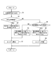
- FIG. 3 is a flowchart of the drive control method according to the first embodiment of the present invention.
- FIG. 4 is a collinear diagram showing the relationship between the rotational speed and torque in the HEV mode and EV mode of the hybrid vehicle to which the drive control method according to the first embodiment of the present invention is applied.
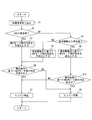
- FIG. 5 is a flowchart showing a modification of the drive control method according to the first embodiment of the present invention.
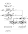
- FIG. 6 is a flowchart of the drive control method according to the second embodiment of the present invention.
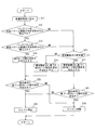
- FIG. 7 is a flowchart showing a modification of the drive control method according to the second embodiment of the present invention.
- the hybrid vehicle and the drive control device set a one-way clutch as an output shaft fixing mechanism that fixes an output shaft of an engine as an internal combustion engine, and a required driving force according to a driver's request A required driving force setting unit, a storage amount detection unit that detects a storage amount of the battery, and a control unit.
- the control unit stops the engine regardless of the magnitude of the required driving force set by the required driving force setting unit when the charged amount of the battery detected by the charged amount detecting unit is equal to or greater than a preset value.
- the output shaft fixing mechanism is operated, and the output shaft of the engine is fixed by the output shaft fixing mechanism, and control is performed so that the vehicle runs only with the power generated from the two motor generators.
- the hybrid vehicle 100 includes a drive mechanism 1 and a drive control device 32.
- the drive mechanism 1 includes an output shaft 3 of an engine 2 and a first motor 4 (also referred to as MG1) that is a first motor generator that generates electric power while being driven by electricity. ) And a second motor 5 (also referred to as MG2) which is a second motor generator, a drive shaft 7 connected to the drive wheels 6 of the hybrid vehicle 100, the output shaft 3, the first motor 4, the second motor 5, A first planetary gear mechanism 8 and a second planetary gear mechanism 9 connected to the drive shaft 7 are provided.
- the first planetary gear mechanism 8 and the second planetary gear mechanism 9 constitute a power transmission mechanism.
- the output shaft 3 is connected to the first planetary gear mechanism 8 and the second planetary gear mechanism 9 via a one-way clutch 40.
- the first motor 4 includes a first motor rotor shaft 13, a first motor rotor 14, and a first motor stator 15.
- the second motor 5 includes a second motor rotor shaft 16, a second motor rotor 17, and a second motor stator 18.
- the first motor stator 15 of the first motor 4 is connected to the first inverter 19.
- the second motor stator 18 of the second motor 5 is connected to the second inverter 20.
- the first motor 4 and the second motor 5 are controlled by the first inverter 19 and the second inverter 20, respectively, and the amount of electricity supplied from the (high voltage) battery 21, which is a power storage device, is controlled and driven by the supplied power.
- the battery 21 is charged by generating electrical energy by driving during regeneration.
- the first planetary gear mechanism 8 includes a first sun gear 22, a first planetary carrier 24 that supports the first planetary gear 23 that meshes with the first sun gear 22, a first ring gear 25 that meshes with the first planetary gear 23, It has.
- the second planetary gear mechanism 9 includes a second sun gear 26, a second planetary carrier 28 that supports a second planetary gear 27 that meshes with the second sun gear 26, a second ring gear 29 that meshes with the second planetary gear 27, It has.
- the rotation center lines of the respective rotating elements are arranged on the same axis, and the first motor 4 is arranged between the engine 2 and the first planetary gear mechanism 8.
- the second motor 5 is arranged on the side away from the engine 2 of the second planetary gear mechanism 9.
- the first motor rotor shaft 13 of the first motor 4 is connected to the first sun gear 22 of the first planetary gear mechanism 8.
- the first planetary carrier 24 of the first planetary gear mechanism 8 and the second sun gear 26 of the second planetary gear mechanism 9 are coupled and connected to the output shaft 3 of the engine 2 via the one-way clutch 40.
- the first ring gear 25 of the first planetary gear mechanism 8 and the second planetary carrier 28 of the second planetary gear mechanism 9 are coupled and coupled to the output unit 30.
- the output unit 30 is connected to the drive shaft 7 via an output transmission mechanism 31 such as a gear or a chain.
- the second motor rotor shaft 16 of the second motor 5 is connected to the second ring gear 29 of the second planetary gear mechanism 9. In such a drive mechanism 1, the driving force is exchanged among the engine 2, the first motor 4, the second motor 5, and the drive shaft 7.
- the drive control device 32 is connected to a storage amount detection unit 33 and an accelerator opening detection unit 34.
- the storage amount detection unit 33 detects the state of charge SOC of the battery 21.
- the accelerator opening detector 34 detects an accelerator opening tvo that is the amount of depression of the accelerator pedal.
- the drive control device 32 includes a storage amount determination unit 35, a required drive force setting unit 36, a required drive force determination unit 37, a vehicle speed detection unit 38, a target charge / discharge power setting unit 39, and a target drive power setting unit 41. And a target engine power setting unit 42 and a target engine operating point calculation unit 43.
- FIG. 2 is a control block diagram showing functions of the storage amount detection unit 33, the storage amount determination unit 35, the required driving force setting unit 36, and the required driving force determination unit 37.
- the storage amount determining unit 35 determines whether or not the state of charge (charge amount) SOC is equal to or greater than a predetermined value (SOClim) as a preset value.
- SOClim state of charge
- the HEV mode failure command that does not shift to the mode is output.
- this predetermined value (SOClim) is set lower than the upper limit of the amount of stored electricity appropriate for charging the battery, and is set to a margin value that does not immediately reach the upper limit even if power generation occurs in the first motor 4 or the like. ing.
- the required driving force setting unit 36 searches and sets the required driving force based on the accelerator opening degree tvo, for example, using a required driving force search map (not shown).
- the required driving force determination unit 37 determines whether or not the required driving force requires a driving force of a predetermined value or more, for example, when a large driving force is required, such as when starting on an uphill with a high degree of inclination. Make a decision.
- the requested driving force setting unit 36 is a request for driving the hybrid vehicle 100 according to the accelerator opening tvo detected by the accelerator opening detecting unit 34 and the vehicle speed Vs detected by the vehicle speed detecting unit 38.
- the driving force Fdrv is searched and set by the required driving force search map.
- the vehicle speed detection unit 38 detects the vehicle speed (vehicle speed) Vs of the hybrid vehicle 100.
- the target charge / discharge power setting unit 39 sets the target charge / discharge power Pbat based on at least the state of charge SOC of the battery 21 detected by the storage amount detection unit 33. In this embodiment, for example, according to the state of charge SOC of the battery 21, the target charge / discharge power Pbat is searched and set, for example, using a target charge / discharge power search map (not shown).
- the target drive power setting unit 41 sets the target drive power Pdrv based on the accelerator opening tvo detected by the accelerator opening detection unit 34 and the vehicle speed Vs detected by the vehicle speed detection unit 38.
- the target driving power Pdrv is set by multiplying the target driving force Fdrv and the vehicle speed Vs.
- the target engine power calculation unit 42 calculates the target engine power Peg from the target drive power Pdrv set by the target drive power setting unit 41 and the target charge / discharge power Pbat calculated by the target charge / discharge power setting unit 39. .
- the target engine power Peg is obtained by subtracting the target charge / discharge power Pbat from the target drive power Pdrv.
- a target engine operating point (target engine rotation speed, target engine torque) corresponding to the target engine power Peg and the vehicle speed is searched and set from a target engine operating point search map (not shown). To do.
- FIG. 3 is a flowchart showing control performed by drive control device 32 of hybrid vehicle 100 according to the present embodiment. This routine is repeatedly executed every predetermined time.
- Step S1 various signals such as a required driving force value calculated based on a stored power (SOC) from the stored power detection unit 33 and an accelerator opening from the accelerator opening detection unit 34 are captured.
- SOC stored power
- step S2 it is determined whether or not the SOC is equal to or higher than a predetermined value (SOClim) lower than the charging upper limit value of the battery 21 (step S2).
- SOClim a predetermined value
- step S3 a command for HEV mode not established (EV mode established) that does not shift to the HEV mode (mode in which the engine 2 and the motor generator are used together) is output ( Step S3).
- the drive control device 32 stops the engine 2 in response to the HEV mode non-established command and fixes the output shaft 3 of the engine 2 so as not to rotate by the one-way clutch 40 (step S7).
- step S2 when the SOC is smaller than the predetermined value (SOClim) (NO), the required driving force at the required driving force determination unit 37 is large, for example, when the vehicle starts on an uphill with a high degree of inclination. It is determined whether or not the driving force is greater than or equal to a predetermined value set when a driving force is required (required driving force ⁇ predetermined value) (step S4).
- step S4 if the required driving force is smaller than the predetermined value (NO), the HEV mode shift determination based on the required driving force is not established (EV mode is established) (step S5), and the drive control device 32 is in response to the HEV mode not established command. Stops the engine 2. At this time, the output shaft 3 of the engine 2 is fixed so as not to rotate by the one-way clutch 40 (step S7).
- step S4 when the required driving force is equal to or greater than a predetermined value (YES), the HEV mode shift determination based on the required driving force is established (step S6).
- step S8 In response to the determination that the transition to the HEV mode is established, the engine 2 is operated (step S8), and control is performed so that the vehicle travels in the HEV mode.
- step S8 the output shaft 3 of the engine 2 is not restricted by the one-way clutch 40.
- hybrid vehicle 100 when the engine 2 is stopped, the output shaft 3 of the engine 2 is fixed in rotation by the one-way clutch 40, so that both the first motor 4 and the second motor 5 are in the power generation state. Therefore, overcharge to the battery 21 can be avoided.
- hybrid vehicle 100 according to the present embodiment can output the driving force requested by the driver in addition to suppressing overcharging of battery 21.
- FIG. 4 shows a collinear diagram of system operating points during traveling at low vehicle speed and high driving force in the HEV mode and EV mode.
- the control in the drive control device 32 causes the travel in such a state to be the travel in the EV mode, so the rotational speed of the engine 2 becomes 0, and the first motor 4 and the second motor 5 Both of them are in a driving state and do not generate power, so there is no overcharging.
- the torque reaction force of the first motor 4 and the second motor 5 is received by the one-way clutch 40, and as shown in FIG. Torque is generated in the output unit (OUT) 30, and even in the EV mode, torque equivalent to that in the HEV mode can be generated in the output unit 30.
- FIG. 5 is a flowchart showing a modification of the drive control method in hybrid vehicle 100 according to the first embodiment.
- step S10 the HEV mode transition determination is performed based on other conditions (step S10).
- the other conditions referred to here include conditions such as the detected value of the tilt angle of the hybrid vehicle 100 and whether or not the snow mode is selected, and even if the HEV mode transition determination is established in step S6.
- a control for selecting a determination not to operate the engine 2 is added.
- FIG. 6 is a flowchart showing a drive control method for hybrid vehicle 100 according to the second embodiment of the present invention.
- the system configuration of hybrid vehicle 100 in the present embodiment is substantially the same as that of hybrid vehicle 100 according to the first embodiment described above, and a description thereof will be omitted. This routine is repeatedly performed every predetermined time.
- step S ⁇ b> 11 the charging power upper limit value, the discharge power upper limit value calculated based on the charged amount (SOC) from the charged amount detection unit 33, and the accelerator opening amount from the accelerator opening degree detection unit 34.
- SOC charged amount
- Various signals such as a required driving force value calculated based on the above are taken in.
- step S12 it is determined whether the charging power upper limit value for the battery 21 is equal to or less than a preset value.
- step S12 when the charging power upper limit value is smaller than the predetermined value (YES), it is determined whether the discharging power upper limit value from the battery 21 is equal to or larger than a preset value (step S13).
- the charge power upper limit value and the discharge power upper limit value are set by the target charge / discharge power setting unit 39 in the drive control device 32 shown in FIG.
- step S13 when the discharge power upper limit value is equal to or greater than a preset value (YES), the HEV mode shift determination is not established (step S14), and the engine 2 is stopped (step S18). At this time, the one-way clutch 40 fixes the output shaft 3 of the engine 2 so as not to rotate.
- step S12 when the charge power upper limit value is larger than the predetermined value (NO), and when the discharge power upper limit value is smaller than the predetermined value in step S13 (NO), the process proceeds to step S15.
- step S15 as in the control in the first embodiment, it is determined whether or not the required driving force is equal to or greater than a predetermined value.
- Step S15 when the required driving force is smaller than the predetermined value (NO), the HEV mode shift determination based on the required driving force is not established (Step S16), and the engine 2 is stopped (Step S18). At this time, the one-way clutch 40 fixes the output shaft 3 of the engine 2 so as not to rotate.
- step S15 if the required driving force is greater than or equal to a predetermined value (YES), the HEV mode shift determination based on the required driving force is established (step S17), the engine 2 is operated, and the process returns.
- the first motor 4 and the second motor 5 is rotated without being in a power generation state, so that overcharging of the battery 21 can be avoided.
- the driving force requested by the driver can be output while suppressing overcharging of the battery 21 in this way.
- the rotational speed of the engine 2 is 0, and neither the first motor 4 nor the second motor 5 is in a driving state and does not generate power, so that overcharging is not caused.
- the torque reaction force of the first motor 4 and the second motor 5 is received by the one-way clutch 40, and the torque of the first motor 4 and the second motor 5 is generated at the output unit (OUT) 30.
- the same torque can be generated in the output unit 30 in both the HEV mode and the EV mode.
- FIG. 7 is a flowchart showing a modification of the drive control method in hybrid vehicle 100 according to the second embodiment.
- step S21 the HEV mode shift determination is performed based on other conditions (step S21), which is different from the second embodiment.
- the other conditions referred to here include conditions such as the detected value of the tilt angle of the hybrid vehicle 100 and whether or not the snow mode is selected, even if the HEV mode transition determination is established in step S17.
- a control for selecting a determination not to operate the engine 2 is added.
- the one-way clutch 40 is applied as the output shaft fixing mechanism that fixes the output shaft 3 of the engine 2.
- the present invention is not limited to this.
- An output shaft in which a member directly connected to the output shaft 3 of the engine 2, for example, the rotation shaft of the first planetary carrier 24 or the second sun gear 26, can be fixed at any time in the power transmission mechanism including the planetary gear mechanisms 8 and 9. Fixing with a fixing mechanism is also within the scope of the present invention.
- the drive mechanism 1 as shown in FIG. 1, the output shaft 3 of the engine 2, the first motor 4 (MG1) and the second motor 5 (MG2), and the drive shaft 7
- the planetary gear mechanism composed of the first planetary gear mechanism 8 and the second planetary gear mechanism 9 to which the four elements are coupled is used, but other planetary gear mechanisms to which the four elements are connected may be used. Needless to say, this is within the scope of the present invention.
Landscapes
- Engineering & Computer Science (AREA)
- Chemical & Material Sciences (AREA)
- Combustion & Propulsion (AREA)
- Transportation (AREA)
- Mechanical Engineering (AREA)
- Automation & Control Theory (AREA)
- Electric Propulsion And Braking For Vehicles (AREA)
- Hybrid Electric Vehicles (AREA)
Abstract
Description
以下、本発明の第1の実施の形態に係る駆動制御方法、駆動制御装置32、およびこの駆動制御装置32を搭載するハイブリッド車両100について図面を用いて説明する。図1に示すように、ハイブリッド車両100は、駆動機構1と、駆動制御装置32とを備えている。
先ず、駆動機構1について説明する。図1に示すように、駆動機構1は、エンジン2の出力軸3と、電気により駆動力を発生するとともに駆動されて電気エネルギーを発生する第1モータジェネレータである第1モータ4(MG1とも記す)および第2モータジェネレータである第2モータ5(MG2とも記す)と、ハイブリッド車両100の駆動輪6に接続される駆動軸7と、上記出力軸3、第1モータ4、第2モータ5、駆動軸7にそれぞれ連結された第1遊星歯車機構8および第2遊星歯車機構9と、を備えている。ここで第1遊星歯車機構8と第2遊星歯車機構9とは、動力伝達機構を構成している。図1に示すように、出力軸3は、ワンウェイクラッチ40を介して第1遊星歯車機構8と第2遊星歯車機構9とに接続されている。
図1に示すように、駆動制御装置32は、蓄電量検出部33と、アクセル開度検出部34と、に接続されている。蓄電量検出部33は、バッテリ21の充電状態SOCを検出する。アクセル開度検出部34は、アクセルペダルの踏み込み量であるアクセル開度tvoを検出する。
図3は、本実施の形態に係るハイブリッド車両100の駆動制御装置32で行う制御を示すフローチャートである。このルーチンは、所定時間毎に繰り返し実行される。
図5は、上記第1の実施の形態に係るハイブリッド車両100における駆動制御方法の変形例を示すフローチャートである。
図6は、本発明の第2の実施の形態に係るハイブリッド車両100の駆動制御方法を示すフローチャートである。なお、本実施の形態におけるハイブリッド車両100のシステム構成は、上記した第1の実施の形態に係るハイブリッド車両100と略同じであるため、説明は省略する。なお、このルーチンは、所定時間毎に繰り返して行われる。
図7は、上記第2の実施の形態に係るハイブリッド車両100における駆動制御方法の変形例を示すフローチャートである。
以上、各実施の形態およびその変形例について説明したが、本発明は、これらの実施の形態の開示の一部をなす論述および図面はこの発明を限定するものではなく、本発明が目的とするものと均等な効果をもたらすすべての実施の形態をも含む。さらに、本発明の範囲は、特許請求の範囲により画される発明の特徴の組み合わせに限定されるものではなく、すべての開示されたそれぞれの特徴のうち特定の特徴のあらゆる所望する組み合わせによって画され得るものである。
2 エンジン(内燃機関)
3 出力軸
4 第1モータ(モータジェネレータ)
5 第2モータ(モータジェネレータ)
6 車輪
7 駆動軸
8 第1遊星歯車機構(動力伝達機構)
9 第2遊星歯車機構(動力伝達機構)
21 バッテリ
30 出力部
32 駆動制御装置
33 蓄電量検出部
34 アクセル開度検出部
35 蓄電量判定部
36 要求駆動力設定部
37 要求駆動力判定部
38 車両速度検出部
39 目標充放電パワー設定部
40 ワンウェイクラッチ
41 目標駆動パワー設定部
42 目標エンジンパワー設定部
43 目標エンジン動作点算出部
100 ハイブリッド車両
Claims (12)
- 内燃機関とモータジェネレータとから発生する動力を、動力伝達機構を介して駆動軸に出力するハイブリッド車両の駆動制御装置であって、
前記内燃機関の出力軸を必要に応じて回転不能となるように、前記出力軸側を固定可能な出力軸固定機構と、
運転者の要求に応じて要求駆動力を設定する要求駆動力設定部と、
バッテリの蓄電量を検出する蓄電量検出部と、
前記蓄電量に基づく条件に応じて、前記要求駆動力の大きさに関係なく、前記内燃機関を停止させ、前記出力軸固定機構により前記出力軸を固定させ、前記モータジェネレータから発生する動力のみで走行するように制御する制御部と、
を備えることを特徴とするハイブリッド車両の駆動制御装置。 - 前記条件は、前記蓄電量が予め設定された値以上であることを特徴とする請求項1に記載のハイブリッド車両の駆動制御装置。
- 前記条件は、前記蓄電量に基づき、前記バッテリへの充電パワー上限値と前記バッテリからの放電パワー上限値を設定したときに、前記バッテリへの充電パワー上限値が予め設定された値以下で、かつ前記バッテリからの放電パワー上限値が予め設定された値以下であることを特徴とする請求項1に記載のハイブリッド車両の駆動制御装置。
- 前記制御部は、前記条件に応じた前記内燃機関を停止させる制御を行わない場合には、
前記要求駆動力が所定値以上であるときに、前記内燃機関と前記モータジェネレータとを駆動する制御を行い、
前記要求駆動力が前記所定値より小さいときに、前記内燃機関を停止させ、前記出力軸固定機構により前記出力軸を固定させ、前記モータジェネレータから発生する動力のみで走行させる制御を行うことを特徴とする請求項1~3のいずれか一つに記載のハイブリッド車両の駆動制御装置。 - 前記モータジェネレータは、第1モータジェネレータと第2モータジェネレータの2つであり、
前記動力伝達機構は、前記内燃機関と、前記第1のモータジェネレータと、前記第2のモータジェネレータと、出力部と、から構成される4つの要素が、共線図上で、前記第1のモータジェネレータ、前記内燃機関、前記出力部、前記第2のモータジェネレータの順になるように連結された遊星歯車機構である、
ことを特徴とする請求項1~4のいずれか一つに記載のハイブリッド車両の駆動制御装置。 - 前記出力軸固定機構は、前記内燃機関の出力軸にその一方向への回転は許容し逆方向への回転は不能とするように接続されたワンウェイクラッチであることを特徴とする請求項1~5のいずれか一つに記載のハイブリッド車両の駆動制御装置。
- 前記出力軸固定機構は、前記遊星歯車機構における前記内燃機関の出力軸に直接接続された部材を回転しないように固定可能であることを特徴とする請求項5に記載のハイブリッド車両の駆動制御装置。
- 内燃機関とモータジェネレータとから発生する動力を、動力伝達機構を介して駆動軸に出力するハイブリッド車両の駆動制御方法であって、
バッテリの蓄電量に基づく条件に応じて、運転者の要求に応じた要求駆動力の大きさに関係なく、前記内燃機関を停止させ、前記内燃機関の出力軸を回転しないように固定させ、前記モータジェネレータから発生する動力のみで走行するように制御することを特徴とするハイブリッド車両の駆動制御方法。 - 前記条件は、前記バッテリの蓄電量が予め設定された値以上であることを特徴とする請求項8に記載のハイブリッド車両の駆動制御方法。
- 前記条件は、前記バッテリの蓄電量に基づき、前記バッテリへの充電パワー上限値と前記バッテリからの放電パワー上限値とを設定したときに、前記バッテリへの充電パワー上限値が予め設定された値以下で、かつ前記バッテリからの放電パワー上限値が予め設定された値以上であることを特徴とする請求項8に記載のハイブリッド車両の駆動制御方法。
- 前記条件に応じた前記内燃機関を停止させる制御を行わない場合には、
前記要求駆動力が所定値以上であるときに、前記内燃機関と前記モータジェネレータとを駆動する制御を行い、
前記要求駆動力が前記所定値より小さいときに、前記内燃機関を停止させ、前記出力軸を回転しないように固定し、前記モータジェネレータから発生する動力のみで走行させる制御を行うことを特徴とする請求項8~10のいずれか一つに記載のハイブリッド車両の駆動制御方法。 - 請求項1~7のいずれか一つに記載の駆動制御装置を備えることを特徴とするハイブリッド車両。
Priority Applications (5)
| Application Number | Priority Date | Filing Date | Title |
|---|---|---|---|
| JP2012555557A JPWO2012104905A1 (ja) | 2011-01-31 | 2011-01-31 | ハイブリッド車両の駆動制御装置、駆動制御方法、およびハイブリッド車両 |
| CN201180066488.2A CN103338999B (zh) | 2011-01-31 | 2011-01-31 | 用于混合动力车辆的驱动控制装置和驱动控制方法及混合动力车辆 |
| US13/981,033 US9002561B2 (en) | 2011-01-31 | 2011-01-31 | Drive control apparatus and drive control method for hybrid vehicles and hybrid vehicle |
| DE112011104809T DE112011104809T5 (de) | 2011-01-31 | 2011-01-31 | Antriebssteuervorrichtung und Antriebssteuerverfahren für Hybridfahrzeuge und Hybridfahrzeug |
| PCT/JP2011/000534 WO2012104905A1 (ja) | 2011-01-31 | 2011-01-31 | ハイブリッド車両の駆動制御装置、駆動制御方法、およびハイブリッド車両 |
Applications Claiming Priority (1)
| Application Number | Priority Date | Filing Date | Title |
|---|---|---|---|
| PCT/JP2011/000534 WO2012104905A1 (ja) | 2011-01-31 | 2011-01-31 | ハイブリッド車両の駆動制御装置、駆動制御方法、およびハイブリッド車両 |
Publications (1)
| Publication Number | Publication Date |
|---|---|
| WO2012104905A1 true WO2012104905A1 (ja) | 2012-08-09 |
Family
ID=46602159
Family Applications (1)
| Application Number | Title | Priority Date | Filing Date |
|---|---|---|---|
| PCT/JP2011/000534 Ceased WO2012104905A1 (ja) | 2011-01-31 | 2011-01-31 | ハイブリッド車両の駆動制御装置、駆動制御方法、およびハイブリッド車両 |
Country Status (5)
| Country | Link |
|---|---|
| US (1) | US9002561B2 (ja) |
| JP (1) | JPWO2012104905A1 (ja) |
| CN (1) | CN103338999B (ja) |
| DE (1) | DE112011104809T5 (ja) |
| WO (1) | WO2012104905A1 (ja) |
Cited By (1)
| Publication number | Priority date | Publication date | Assignee | Title |
|---|---|---|---|---|
| JPWO2012104905A1 (ja) * | 2011-01-31 | 2014-07-03 | スズキ株式会社 | ハイブリッド車両の駆動制御装置、駆動制御方法、およびハイブリッド車両 |
Families Citing this family (9)
| Publication number | Priority date | Publication date | Assignee | Title |
|---|---|---|---|---|
| CN104417544B (zh) | 2013-09-09 | 2017-08-22 | 比亚迪股份有限公司 | 混合动力汽车的控制系统和控制方法 |
| CN104417346B (zh) | 2013-09-09 | 2017-04-12 | 比亚迪股份有限公司 | 混合动力汽车的控制系统和控制方法 |
| CN104417557B (zh) | 2013-09-09 | 2017-07-04 | 比亚迪股份有限公司 | 一种车辆的滑行回馈控制系统及其控制方法 |
| CN104417554B (zh) | 2013-09-09 | 2018-03-13 | 比亚迪股份有限公司 | 混合动力汽车及其的巡航控制方法 |
| CN104417543B (zh) | 2013-09-09 | 2017-08-22 | 比亚迪股份有限公司 | 混合动力汽车的控制系统和控制方法 |
| CN104417347B (zh) * | 2013-09-09 | 2017-08-04 | 比亚迪股份有限公司 | 混合动力汽车的控制系统和控制方法 |
| JP6136949B2 (ja) * | 2014-01-24 | 2017-05-31 | トヨタ自動車株式会社 | ハイブリッド車の制御装置 |
| KR101724465B1 (ko) * | 2015-08-17 | 2017-04-07 | 현대자동차 주식회사 | 하이브리드 차량의 엔진 기동 제어 방법 및 장치 |
| DE102017222547A1 (de) * | 2017-12-13 | 2019-06-13 | Robert Bosch Gmbh | Verfahren zum Betreiben eines Fahrzeugs mit wenigstens zwei Antriebseinheiten |
Citations (5)
| Publication number | Priority date | Publication date | Assignee | Title |
|---|---|---|---|---|
| JPS59204402A (ja) * | 1983-05-06 | 1984-11-19 | Nissan Motor Co Ltd | ハイブリッド自動車用走行制御装置 |
| JP2007283815A (ja) * | 2006-04-13 | 2007-11-01 | Suzuki Motor Corp | ハイブリッド車両の駆動制御装置 |
| JP2008094238A (ja) * | 2006-10-11 | 2008-04-24 | Nissan Motor Co Ltd | ハイブリッド車の制御装置 |
| WO2010070706A1 (ja) * | 2008-12-18 | 2010-06-24 | 本田技研工業株式会社 | ハイブリット車両の動力伝達装置 |
| JP2010269692A (ja) * | 2009-05-21 | 2010-12-02 | Toyota Motor Corp | ハイブリッド車両の駆動装置 |
Family Cites Families (34)
| Publication number | Priority date | Publication date | Assignee | Title |
|---|---|---|---|---|
| JP3402236B2 (ja) * | 1999-01-13 | 2003-05-06 | トヨタ自動車株式会社 | 動力出力装置およびハイブリッド車両並びにその制御方法 |
| JP3213293B2 (ja) * | 1999-08-02 | 2001-10-02 | 本田技研工業株式会社 | エンジン制御装置 |
| JP3933106B2 (ja) * | 2003-07-30 | 2007-06-20 | トヨタ自動車株式会社 | 動力出力装置およびその制御方法並びに自動車 |
| US7127337B2 (en) * | 2003-10-14 | 2006-10-24 | General Motors Corporation | Silent operating mode for reducing emissions of a hybrid electric vehicle |
| US7204222B2 (en) * | 2004-02-17 | 2007-04-17 | Toyota Jidosha Kabushiki Kaisha | Drive system and automobile |
| JP3812570B2 (ja) * | 2004-02-25 | 2006-08-23 | 日産自動車株式会社 | ハイブリッド車両の駆動装置 |
| JP4165483B2 (ja) * | 2004-05-11 | 2008-10-15 | トヨタ自動車株式会社 | 動力出力装置およびこれを搭載する自動車並びに動力出力装置の制御方法 |
| US20100145562A1 (en) * | 2004-12-01 | 2010-06-10 | Ise Corporation | Method of Controlling Engine Stop-Start Operation for Heavy-Duty Hybrid-Electric Vehicles |
| JP4123254B2 (ja) * | 2005-07-27 | 2008-07-23 | トヨタ自動車株式会社 | 内燃機関の失火判定装置および内燃機関の失火判定方法 |
| JP4207966B2 (ja) * | 2005-08-25 | 2009-01-14 | トヨタ自動車株式会社 | 動力出力装置およびその制御方法並びに車両 |
| US7632212B2 (en) * | 2005-11-25 | 2009-12-15 | Toyota Jidosha Kabushiki Kaisha | Hybrid vehicle and control method of the same |
| FR2894547B1 (fr) * | 2005-12-08 | 2009-06-05 | Renault Sas | Procede et dispositif de controle et de supervision d'un vehicule hybride du type comportant quatre roues motrices |
| JP2007168495A (ja) * | 2005-12-19 | 2007-07-05 | Toyota Motor Corp | 動力出力装置及びその制御方法並びに車両 |
| JP4462224B2 (ja) * | 2006-03-31 | 2010-05-12 | マツダ株式会社 | 車両のハイブリッドシステム |
| JP4229165B2 (ja) * | 2006-10-13 | 2009-02-25 | トヨタ自動車株式会社 | 車両およびその制御方法 |
| JP4321641B2 (ja) * | 2007-08-09 | 2009-08-26 | トヨタ自動車株式会社 | ハイブリッド車両、ハイブリッド車両の制御方法およびその制御方法をコンピュータに実行させるためのプログラムを記録したコンピュータ読取可 |
| CN101878142B (zh) * | 2007-11-30 | 2014-03-12 | 博世株式会社 | 混合动力系统控制方法 |
| CN101612883B (zh) * | 2008-06-24 | 2013-01-30 | 比亚迪股份有限公司 | 一种混合动力驱动系统及其驱动方法 |
| JP2009220788A (ja) | 2008-03-18 | 2009-10-01 | Toyota Motor Corp | ハイブリッド車両 |
| JP4535184B2 (ja) * | 2008-09-18 | 2010-09-01 | トヨタ自動車株式会社 | ハイブリッド車両の制御装置 |
| JP4780219B2 (ja) * | 2009-04-02 | 2011-09-28 | トヨタ自動車株式会社 | 動力出力装置、それを備えたハイブリッド自動車および動力出力装置の制御方法 |
| WO2010137119A1 (ja) * | 2009-05-26 | 2010-12-02 | トヨタ自動車株式会社 | ハイブリッド自動車およびその走行モードの設定方法 |
| JP5234179B2 (ja) * | 2009-06-02 | 2013-07-10 | トヨタ自動車株式会社 | 電動車両の電源システムおよびその制御方法 |
| JP5305025B2 (ja) * | 2009-07-06 | 2013-10-02 | スズキ株式会社 | ハイブリッド車両 |
| WO2011045965A1 (ja) * | 2009-10-13 | 2011-04-21 | 本田技研工業株式会社 | ハイブリッド車両 |
| US8463476B2 (en) * | 2009-11-30 | 2013-06-11 | Toyota Jidosha Kabushiki Kaisha | Hybrid vehicle control apparatus |
| CN103338999B (zh) * | 2011-01-31 | 2016-03-02 | 铃木株式会社 | 用于混合动力车辆的驱动控制装置和驱动控制方法及混合动力车辆 |
| JPWO2012104924A1 (ja) * | 2011-02-03 | 2014-07-03 | スズキ株式会社 | ハイブリッド車両の駆動制御装置及びその方法、並びにハイブリッド車両 |
| CN103347760B (zh) * | 2011-02-16 | 2015-11-25 | 铃木株式会社 | 混合动力车辆的驱动控制装置以及混合动力车辆 |
| DE112011104904T5 (de) * | 2011-02-17 | 2013-12-05 | Suzuki Motor Corporation | Antriebssteuergerät eines hybriden Fahrzeugs Fachgebiet |
| WO2012114431A1 (ja) * | 2011-02-21 | 2012-08-30 | スズキ株式会社 | ハイブリッド車両の駆動制御装置 |
| CN103402840B (zh) * | 2011-02-21 | 2015-12-02 | 铃木株式会社 | 混合动力车辆的驱动控制装置 |
| CN103380043B (zh) * | 2011-02-21 | 2015-12-16 | 铃木株式会社 | 混合动力车辆的驱动控制装置 |
| JP6119966B2 (ja) * | 2012-12-21 | 2017-04-26 | 三菱自動車工業株式会社 | ハイブリッド車の走行モード切換制御装置 |
-
2011
- 2011-01-31 CN CN201180066488.2A patent/CN103338999B/zh active Active
- 2011-01-31 WO PCT/JP2011/000534 patent/WO2012104905A1/ja not_active Ceased
- 2011-01-31 US US13/981,033 patent/US9002561B2/en active Active
- 2011-01-31 JP JP2012555557A patent/JPWO2012104905A1/ja active Pending
- 2011-01-31 DE DE112011104809T patent/DE112011104809T5/de active Pending
Patent Citations (5)
| Publication number | Priority date | Publication date | Assignee | Title |
|---|---|---|---|---|
| JPS59204402A (ja) * | 1983-05-06 | 1984-11-19 | Nissan Motor Co Ltd | ハイブリッド自動車用走行制御装置 |
| JP2007283815A (ja) * | 2006-04-13 | 2007-11-01 | Suzuki Motor Corp | ハイブリッド車両の駆動制御装置 |
| JP2008094238A (ja) * | 2006-10-11 | 2008-04-24 | Nissan Motor Co Ltd | ハイブリッド車の制御装置 |
| WO2010070706A1 (ja) * | 2008-12-18 | 2010-06-24 | 本田技研工業株式会社 | ハイブリット車両の動力伝達装置 |
| JP2010269692A (ja) * | 2009-05-21 | 2010-12-02 | Toyota Motor Corp | ハイブリッド車両の駆動装置 |
Cited By (1)
| Publication number | Priority date | Publication date | Assignee | Title |
|---|---|---|---|---|
| JPWO2012104905A1 (ja) * | 2011-01-31 | 2014-07-03 | スズキ株式会社 | ハイブリッド車両の駆動制御装置、駆動制御方法、およびハイブリッド車両 |
Also Published As
| Publication number | Publication date |
|---|---|
| US9002561B2 (en) | 2015-04-07 |
| CN103338999B (zh) | 2016-03-02 |
| CN103338999A (zh) | 2013-10-02 |
| JPWO2012104905A1 (ja) | 2014-07-03 |
| US20130304295A1 (en) | 2013-11-14 |
| DE112011104809T5 (de) | 2013-10-24 |
Similar Documents
| Publication | Publication Date | Title |
|---|---|---|
| WO2012104905A1 (ja) | ハイブリッド車両の駆動制御装置、駆動制御方法、およびハイブリッド車両 | |
| CN103380046B (zh) | 混合动力车辆的驱动控制装置 | |
| KR101371476B1 (ko) | 하이브리드 자동차의 배터리 충전 방법 및 시스템 | |
| JP5742854B2 (ja) | ハイブリッド車両用駆動源制御装置およびハイブリッド車両用駆動源制御方法並びにハイブリッド車両 | |
| JP5648984B2 (ja) | ハイブリッド車両 | |
| JP5729475B2 (ja) | 車両および車両の制御方法 | |
| CN103380047B (zh) | 混合动力车辆的驱动控制装置 | |
| JP4803101B2 (ja) | ハイブリッド車両の動力出力装置 | |
| WO2012111040A1 (ja) | ハイブリッド車両の駆動制御装置及びハイブリッド車両 | |
| JP5598555B2 (ja) | 車両および車両用制御方法 | |
| JP2020082925A (ja) | 車両の制御装置 | |
| JP2008012992A (ja) | ハイブリッド車両の駆動制御装置 | |
| KR101518898B1 (ko) | 플러그인 하이브리드 자동차의 충전지향모드 제어장치 및 방법 | |
| JP2015112937A (ja) | ハイブリッド駆動装置の制御装置 | |
| JP2011239629A (ja) | 電動車両の制御装置 | |
| JP2016043701A (ja) | ハイブリッド車両の制御装置 | |
| KR20140071593A (ko) | 하이브리드 차량의 충전 제어 방법 | |
| JP4107191B2 (ja) | 車両の制御装置 | |
| WO2012137301A1 (ja) | 車両およびその制御方法 | |
| JP4135032B2 (ja) | 車両の制御装置 | |
| JP6133721B2 (ja) | 自動車 | |
| JPWO2012104963A1 (ja) | ハイブリッド車両 | |
| WO2017013843A1 (ja) | 車両用電源装置および車両用電源装置の制御方法 | |
| JP2014043183A (ja) | ハイブリッド車両 | |
| JP6733283B2 (ja) | ハイブリッド車両 |
Legal Events
| Date | Code | Title | Description |
|---|---|---|---|
| 121 | Ep: the epo has been informed by wipo that ep was designated in this application |
Ref document number: 11857909 Country of ref document: EP Kind code of ref document: A1 |
|
| WWE | Wipo information: entry into national phase |
Ref document number: 13981033 Country of ref document: US |
|
| ENP | Entry into the national phase |
Ref document number: 2012555557 Country of ref document: JP Kind code of ref document: A |
|
| WWE | Wipo information: entry into national phase |
Ref document number: 112011104809 Country of ref document: DE Ref document number: 1120111048092 Country of ref document: DE |
|
| 122 | Ep: pct application non-entry in european phase |
Ref document number: 11857909 Country of ref document: EP Kind code of ref document: A1 |