WO2012098687A1 - 車両制御装置 - Google Patents
車両制御装置 Download PDFInfo
- Publication number
- WO2012098687A1 WO2012098687A1 PCT/JP2011/051130 JP2011051130W WO2012098687A1 WO 2012098687 A1 WO2012098687 A1 WO 2012098687A1 JP 2011051130 W JP2011051130 W JP 2011051130W WO 2012098687 A1 WO2012098687 A1 WO 2012098687A1
- Authority
- WO
- WIPO (PCT)
- Prior art keywords
- vehicle
- engine
- vehicle speed
- internal combustion
- combustion engine
- Prior art date
Links
Images


Classifications
-
- F—MECHANICAL ENGINEERING; LIGHTING; HEATING; WEAPONS; BLASTING
- F02—COMBUSTION ENGINES; HOT-GAS OR COMBUSTION-PRODUCT ENGINE PLANTS
- F02N—STARTING OF COMBUSTION ENGINES; STARTING AIDS FOR SUCH ENGINES, NOT OTHERWISE PROVIDED FOR
- F02N11/00—Starting of engines by means of electric motors
- F02N11/08—Circuits or control means specially adapted for starting of engines
- F02N11/0814—Circuits or control means specially adapted for starting of engines comprising means for controlling automatic idle-start-stop
-
- F—MECHANICAL ENGINEERING; LIGHTING; HEATING; WEAPONS; BLASTING
- F02—COMBUSTION ENGINES; HOT-GAS OR COMBUSTION-PRODUCT ENGINE PLANTS
- F02D—CONTROLLING COMBUSTION ENGINES
- F02D29/00—Controlling engines, such controlling being peculiar to the devices driven thereby, the devices being other than parts or accessories essential to engine operation, e.g. controlling of engines by signals external thereto
- F02D29/02—Controlling engines, such controlling being peculiar to the devices driven thereby, the devices being other than parts or accessories essential to engine operation, e.g. controlling of engines by signals external thereto peculiar to engines driving vehicles; peculiar to engines driving variable pitch propellers
-
- F—MECHANICAL ENGINEERING; LIGHTING; HEATING; WEAPONS; BLASTING
- F02—COMBUSTION ENGINES; HOT-GAS OR COMBUSTION-PRODUCT ENGINE PLANTS
- F02D—CONTROLLING COMBUSTION ENGINES
- F02D41/00—Electrical control of supply of combustible mixture or its constituents
-
- F—MECHANICAL ENGINEERING; LIGHTING; HEATING; WEAPONS; BLASTING
- F02—COMBUSTION ENGINES; HOT-GAS OR COMBUSTION-PRODUCT ENGINE PLANTS
- F02N—STARTING OF COMBUSTION ENGINES; STARTING AIDS FOR SUCH ENGINES, NOT OTHERWISE PROVIDED FOR
- F02N11/00—Starting of engines by means of electric motors
- F02N11/08—Circuits or control means specially adapted for starting of engines
- F02N11/0814—Circuits or control means specially adapted for starting of engines comprising means for controlling automatic idle-start-stop
- F02N11/0818—Conditions for starting or stopping the engine or for deactivating the idle-start-stop mode
- F02N11/0833—Vehicle conditions
-
- F—MECHANICAL ENGINEERING; LIGHTING; HEATING; WEAPONS; BLASTING
- F02—COMBUSTION ENGINES; HOT-GAS OR COMBUSTION-PRODUCT ENGINE PLANTS
- F02N—STARTING OF COMBUSTION ENGINES; STARTING AIDS FOR SUCH ENGINES, NOT OTHERWISE PROVIDED FOR
- F02N2200/00—Parameters used for control of starting apparatus
- F02N2200/08—Parameters used for control of starting apparatus said parameters being related to the vehicle or its components
- F02N2200/0801—Vehicle speed
-
- F—MECHANICAL ENGINEERING; LIGHTING; HEATING; WEAPONS; BLASTING
- F02—COMBUSTION ENGINES; HOT-GAS OR COMBUSTION-PRODUCT ENGINE PLANTS
- F02N—STARTING OF COMBUSTION ENGINES; STARTING AIDS FOR SUCH ENGINES, NOT OTHERWISE PROVIDED FOR
- F02N2200/00—Parameters used for control of starting apparatus
- F02N2200/10—Parameters used for control of starting apparatus said parameters being related to driver demands or status
- F02N2200/101—Accelerator pedal position
-
- F—MECHANICAL ENGINEERING; LIGHTING; HEATING; WEAPONS; BLASTING
- F02—COMBUSTION ENGINES; HOT-GAS OR COMBUSTION-PRODUCT ENGINE PLANTS
- F02N—STARTING OF COMBUSTION ENGINES; STARTING AIDS FOR SUCH ENGINES, NOT OTHERWISE PROVIDED FOR
- F02N2200/00—Parameters used for control of starting apparatus
- F02N2200/10—Parameters used for control of starting apparatus said parameters being related to driver demands or status
- F02N2200/102—Brake pedal position
-
- Y—GENERAL TAGGING OF NEW TECHNOLOGICAL DEVELOPMENTS; GENERAL TAGGING OF CROSS-SECTIONAL TECHNOLOGIES SPANNING OVER SEVERAL SECTIONS OF THE IPC; TECHNICAL SUBJECTS COVERED BY FORMER USPC CROSS-REFERENCE ART COLLECTIONS [XRACs] AND DIGESTS
- Y02—TECHNOLOGIES OR APPLICATIONS FOR MITIGATION OR ADAPTATION AGAINST CLIMATE CHANGE
- Y02T—CLIMATE CHANGE MITIGATION TECHNOLOGIES RELATED TO TRANSPORTATION
- Y02T10/00—Road transport of goods or passengers
- Y02T10/10—Internal combustion engine [ICE] based vehicles
- Y02T10/40—Engine management systems
Definitions
- the present invention relates to a vehicle control device.
- Patent Document 1 discloses a vehicle control device that performs idle stop control under predetermined conditions.
- This vehicle control device stops the engine on condition that the accelerator is off, the brake is on, and the vehicle speed is a predetermined vehicle speed or less (for example, 20 km / h or less). Restart the engine on condition that it is off.
- the vehicle control apparatus described in Patent Document 1 as described above has room for further improvement in terms of, for example, suppression of fuel consumption.
- the present invention has been made in view of the above circumstances, and an object thereof is to provide a vehicle control device capable of suppressing fuel consumption.
- the vehicle control apparatus enables an idle operation of an internal combustion engine that generates power to be applied to the driving wheels of the vehicle when the vehicle speed is lower than a predetermined vehicle speed set in advance. And when the vehicle speed of the said vehicle is more than the said predetermined vehicle speed, the control which makes the said idle driving
- the internal combustion engine can be started when the vehicle speed is lower than the predetermined vehicle speed when the vehicle is in a state other than the state in which the vehicle is accelerated, and the vehicle speed is Control that disables starting of the internal combustion engine when the vehicle speed is equal to or higher than a predetermined vehicle speed may be executed.
- the vehicle control device may execute a control for changing the start mode of the internal combustion engine according to the vehicle speed when the braking operation on the vehicle is released.
- the vehicle control device when the vehicle speed of the vehicle is equal to or higher than the predetermined vehicle speed during inertial traveling in which the consumption of fuel in the internal combustion engine is stopped and the vehicle travels inertially, the braking operation for the vehicle is performed.
- the control which prohibits the starting of the said internal combustion engine according to it can be performed.
- the vehicle control device may execute control for changing the start mode of the internal combustion engine based on the surrounding environment information of the vehicle.
- a control for changing a start mode of the internal combustion engine during traveling of the vehicle that stops consumption of fuel in the internal combustion engine in accordance with an operation to the change operation member is executed. It can be.
- the change operation member has a shift range, a drive range that allows the internal combustion engine to start in response to a braking operation on the vehicle, and the internal combustion engine in response to a braking operation on the vehicle. It is possible to select a free-run range that disables starting of the vehicle.
- the vehicle control device drives the vehicle when the vehicle speed is lower than a predetermined vehicle speed set in advance when the vehicle is in a state other than the state where the vehicle is accelerated. It is possible to start an internal combustion engine that generates power to be applied to the wheels, and to perform control to disable the start of the internal combustion engine when the vehicle speed of the vehicle is equal to or higher than the predetermined vehicle speed.
- a vehicle control device sets the start mode of an internal combustion engine that generates power to be applied to drive wheels of a vehicle to a vehicle speed when the braking operation on the vehicle is released. It is characterized by executing control that changes according to the above.
- the vehicle control device stops the consumption of fuel in the internal combustion engine that generates power to be applied to the drive wheels of the vehicle, and during inertial traveling that causes the vehicle to travel inertially,
- the vehicle speed of the vehicle is equal to or higher than a predetermined vehicle speed set in advance, control for prohibiting starting of the internal combustion engine according to a braking operation on the vehicle is executed.
- a vehicle control device configured to start the internal combustion engine while the vehicle is running while stopping the consumption of fuel in the internal combustion engine that generates power to be applied to drive wheels of the vehicle. Control which changes a mode according to operation to a change operation member is performed, It is characterized by the above-mentioned.
- the vehicle control device according to the present invention has an effect that fuel consumption can be suppressed.
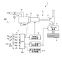
- FIG. 1 is a schematic configuration diagram of a vehicle control system according to the first embodiment.
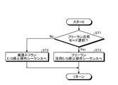
- FIG. 2 is a flowchart for explaining an example of control by the ECU.
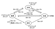
- FIG. 3 is a schematic diagram for explaining an E / G stop operation sequence in the deceleration eco-run mode.
- FIG. 4 is a schematic diagram for explaining an E / G stop operation sequence in the free-run utilization mode.
- FIG. 5 is a time chart for explaining an example of control by the ECU.
- FIG. 6 is a schematic configuration diagram of a vehicle control system according to the second embodiment.
- FIG. 7 is a schematic diagram illustrating an E / G stop operation sequence in the free run utilization mode.
- FIG. 8 is a schematic configuration diagram of a vehicle control system according to the third embodiment.
- FIG. 9 is a flowchart illustrating an example of control by the ECU.
- FIG. 10 is a schematic diagram for explaining an E / G stop operation sequence in the free run only mode.
- FIG. 11 is a time
- FIG. 1 is a schematic configuration diagram of a vehicle control system according to the first embodiment
- FIG. 2 is a flowchart illustrating an example of control by an ECU
- FIG. 3 is a schematic diagram illustrating an E / G stop operation sequence in a deceleration eco-run mode
- FIG. 4 is a schematic diagram for explaining an E / G stop operation sequence in the free run utilization mode
- FIG. 5 is a time chart for explaining an example of control by the ECU.
- the vehicle control system 1 is applied to a so-called two-pedal vehicle 2 equipped with a transmission 10 that is an automatic transmission, as shown in FIG.
- the vehicle control system 1 is a system for controlling each part of the vehicle 2. For example, while the vehicle 2 is traveling, the operation of the engine 4 is stopped and an idling stop is executed.
- This is a free-run eco-run system that reduces the wasteful driving area of the engine 4 as much as possible, suppresses fuel consumption, and improves fuel efficiency by performing so-called free-run using the inertial running state.
- the vehicle control system 1 includes an engine 4 as an internal combustion engine that generates power for driving the drive wheels 3, a power transmission device 5 that forms a power transmission system that transmits the power generated by the engine 4 to the drive wheels 3, A brake device 6 as a braking device of the vehicle 2, a state detection device 7 that detects the state of the vehicle 2, and an ECU 8 as a vehicle control device that controls each part of the vehicle 2 including the vehicle control system 1 are provided.
- the ECU 8 executes free-run S & S (stop and start) operation sequence control in the vehicle 2 equipped with the transmission 10 which is an automatic transmission.
- the engine 4 is a driving source (motor) for driving the vehicle 2.
- the engine 4 generates power that acts on the drive wheels 3 of the vehicle 2 as the fuel burns.
- the engine 4 can switch between an operating state and a non-operating state while the vehicle 2 is traveling.
- the operating state of the engine 4 (the state in which the engine 4 is operated) is a state in which power is generated, and thermal energy generated by burning fuel in the combustion chamber is output in the form of mechanical energy such as torque. It is a state to do.
- the non-operating state of the engine 4 that is, the state in which the operation of the engine 4 is stopped is a state in which the generation of power is stopped, the supply of fuel to the combustion chamber is stopped (fuel cut), and the combustion chamber In this state, the fuel is not burned and no mechanical energy such as torque is output.
- the power transmission device 5 includes a torque converter 9 that is a fluid transmission device with a lock-up clutch, a transmission 10 that shifts and outputs power from the engine 4, a differential gear 11 that is coupled to the transmission 10, and a differential gear 11.
- a drive shaft 12 that connects the drive wheels 3 is included.
- the transmission 10 is a so-called automatic transmission that automatically changes the gear ratio (shift speed) according to the traveling state of the vehicle 2, for example, a stepped automatic transmission (AT), a continuously variable automatic transmission (CVT).
- Various automatic transmissions such as a multi-mode manual transmission (MMT), a sequential manual transmission (SMT), and a dual clutch transmission (DCT) are applied.
- the operation of the transmission 10 is controlled by the ECU 8.
- the power generated by the engine 4 is input to the transmission 10 via the torque converter 9, and is shifted at a predetermined gear ratio by the transmission 10, and is supplied to the drive wheels 3 via the differential gear 11 and the drive shaft 12. Communicated. As a result, the driving force [N] is generated on the contact surface with the road surface of the driving wheel 3, and the vehicle 2 can travel by this.
- the brake device 6 applies a braking force to the wheels including the drive wheels 3.
- the vehicle 2 can be braked by the braking force [N] generated on the contact surface with the road surface of the drive wheel 3.
- the state detection device 7 is electrically connected to the ECU 8 and can exchange information such as a detection signal, a drive signal, and a control command with each other.
- the state detection device 7 includes, for example, an engine speed sensor 71 that detects the engine speed, an accelerator position sensor 72 that detects an accelerator position that is an operation amount (accelerator operation amount) of the accelerator pedal 72a by the driver, and a driver.
- the brake pedal 73a detects the amount of operation of the brake pedal 73a, for example, the master cylinder pressure and the like, the brake sensor 73 detects the braking force, the vehicle speed sensor 74 detects the vehicle speed that is the traveling speed of the vehicle 2, and the shift that the driver performs the shift range operation.
- a shift position sensor 75 for detecting the position of the lever 75a for example, a parking range, a reverse range, a neutral range, a drive range, etc.
- a shift position sensor 75 for detecting the position of the lever 75a for example, a parking range, a reverse range, a neutral range, a drive range, etc.
- the ECU 8 is an electronic circuit mainly composed of a known microcomputer including a CPU, a ROM, a RAM, and an interface.
- the ECU 8 receives an electrical signal corresponding to the detection result from the state detection device 7, and controls the power transmission device 5 including the engine 4, the transmission 10, etc., the brake device 6 and the like according to the input detection result and the like.
- the power transmission device 5 and the brake device 6 including the transmission 10 and the like are hydraulic devices that are operated by the pressure (hydraulic pressure) of the hydraulic oil
- the ECU 8 is a TM hydraulic control device 13 and a brake hydraulic control device, respectively.
- the operations of the transmission 10 and the brake device 6 are controlled via 14 or the like.
- the ECU 8 can detect On / Off of an accelerator operation (Acc) that is an acceleration operation on the vehicle 2 by the driver based on a detection result by the accelerator opening sensor 72.
- the ECU 8 can detect On / Off of a brake operation (Brk), which is a braking operation on the vehicle 2 by the driver, based on a detection result by the brake sensor 73, for example.
- the state where the accelerator operation by the driver is Off is a state where the driver releases the acceleration operation on the vehicle 2, and the accelerator pedal 72 a is released by the driver and the accelerator opening sensor 72
- the detected accelerator opening is smaller than a predetermined opening.
- the state where the accelerator operation by the driver is On is a state where the driver is performing an acceleration operation on the vehicle 2, and the accelerator pedal 72a is depressed by the driver and the accelerator position sensor 72 is depressed. Is the state in which the accelerator opening detected by is equal to or greater than a predetermined opening.
- the state in which the brake operation by the driver is Off is a state in which the driver releases the braking operation on the vehicle 2 and is detected by the brake sensor 73 when the brake pedal 73a is released by the driver.
- the master cylinder pressure (brake operation amount) is smaller than a predetermined pressure.
- the state in which the brake operation by the driver is On is a state in which the driver is performing a braking operation on the vehicle 2 and is detected by the brake sensor 73 when the brake pedal 73a is depressed by the driver. This is a state where the master cylinder pressure is equal to or higher than a predetermined pressure.
- the ECU 8 controls the throttle device 15 of the engine 4 based on the accelerator opening, the vehicle speed, etc., adjusts the throttle opening of the intake passage 16, and adjusts the intake air amount,
- the fuel injection amount is controlled in accordance with the change, and the output of the engine 4 is controlled by adjusting the amount of the air-fuel mixture filled in the combustion chamber.
- the ECU 8 controls the TM hydraulic control device 13 based on the accelerator opening, the vehicle speed, and the like, and controls the gear ratio of the transmission 10.
- the ECU 8 can start or stop the operation of the engine 4 while the vehicle 2 is traveling, and can switch between an operation state and a non-operation state of the engine 4.
- This vehicle control system 1 is a fuel cut control in which the ECU 8 stops the fuel supply to the combustion chamber of the engine 4 as a control relating to the free run S & S when the driver performs a predetermined operation sequence while the vehicle 2 is traveling. Is executed, the idling stop is executed to stop the operation of the engine 4, and the vehicle 2 can be shifted to coasting (coast down), that is, the control can be shifted to a so-called free run state.
- the driving wheel 3 and the engine 4 are connected to each other by various engagement devices included in the power transmission device 5 and various clutches for realizing each gear stage by the transmission 10.
- the state is released, and the power transmission between the engine 4 and the drive wheel 3 is cut off (for example, a state corresponding to the neutral range).
- the vehicle control system 1 can perform a so-called free run in which the vehicle 2 is coasted without stopping the consumption of fuel in the engine 4 and the engine brake or the like is not applied while the vehicle 2 is traveling. This can improve fuel efficiency.
- the ECU 8 can restart the engine 4 and return to normal driving in which the vehicle 2 is driven by the power generated by the engine 4 again.
- the vehicle control system 1 of the present embodiment sets the idling stop by stopping the operation of the engine 4 when the vehicle 2 decelerates and stops as the driving mode of the vehicle 2 mainly due to the brake operation (braking operation) of the driver.
- the deceleration eco-run mode (first travel mode) for executing the engine and the deceleration of the vehicle 2 accompanying the brake operation, not only when the vehicle is stopped, the engine 4 is actively stopped and the idling stop is executed to
- the free run utilization mode (second traveling mode) to be utilized can be selected.
- the vehicle control system 1 includes a free-run utilization mode switch 76.
- ECU8 determines whether the free run utilization mode is selected based on On / Off of the free run utilization mode switch 76, for example as shown in the flowchart of FIG. 2 (ST1).
- the ECU 8 stops the operation of the engine 4 and starts the engine 4 when the free-run utilization mode switch 76 is turned off and the deceleration eco-run mode is selected as the travel mode of the vehicle 2 (ST1: No).
- a deceleration eco-run E / G stop operation sequence is applied as an operation sequence for performing (Step ST2), the current control cycle is terminated, and a transition is made to the next control cycle.
- the ECU 8 operates the engine 4.
- a free-run utilizing E / G stop operation sequence is applied (ST3), the current control cycle is terminated, and the next control cycle is started.
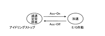
- the ECU 8 stops the operation of the engine 4 and starts the engine 4 in accordance with, for example, a deceleration eco-run E / G stop operation sequence illustrated in FIG.
- the ECU 8 can estimate that the vehicle state is “accelerated or steady” and “decelerate or stop” based on the brake operation On / Off, the vehicle speed Vx, and the like. And the transition of the engine 4 is grasped, and the operation of the engine 4 is stopped and the engine 4 is started according to this.
- the vehicle When the ECU 8 is in the deceleration eco-run mode, the vehicle is detected by the vehicle speed sensor 74 when the braking operation by the driver is Off (Brk-Off) and the braking operation is On (Brk-On).
- the vehicle speed Vx of 2 When the vehicle speed Vx of 2 is lower than the deceleration eco-run start vehicle speed X [Km / h] as a predetermined vehicle speed set in advance (Vx ⁇ X), the operation of the engine 4 is stopped and idling stop is executed.
- the ECU 8 determines that the brake operation is set to On (Brk-On) and the vehicle brake speed is Off (Vx ⁇ X) when the vehicle speed Vx is lower than the deceleration eco-run start vehicle speed X [Km / h] (Vx ⁇ X). Brk-Off), the engine 4 is started and put into an operating state.
- the deceleration eco-run start vehicle speed X [Km / h] is set in advance based on the actual vehicle evaluation and stored in the storage unit of the ECU 8, and is set to, for example, about several [Km / h] to several tens [Km / h]. Is done.
- the state in which the brake operation by the driver is Off is a state in which it can be estimated that the vehicle state of the vehicle 2 is “acceleration or steady”.
- the brake operation by the driver is On (Brk-On) and the vehicle speed Vx is lower than the deceleration eco-run start vehicle speed X (Vx ⁇ X)
- the vehicle state of the vehicle 2 is “decelerate or stop. It is in a state where it can be estimated that.
- the vehicle control system 1 can perform a deceleration eco-run that stops the operation of the engine 4 and executes an idling stop when the vehicle 2 stops from a deceleration travel of the vehicle 2 mainly due to a driver's braking operation (braking operation). Thereby, fuel consumption can be suppressed and fuel consumption can be improved.
- the ECU 8 enables the idle operation of the engine 4 when the vehicle speed Vx is lower than the preset deceleration eco-run start vehicle speed X in the free-run utilization mode, and the vehicle speed Vx is equal to or higher than the deceleration eco-run start vehicle speed X.
- a control for disabling the idle operation of the engine 4 is executed. That is, the ECU 8 can change the idle operation mode of the engine 4 to an idle permission mode that enables idle operation and an idle prohibition mode that disables idle operation.
- the ECU 8 sets the idle operation mode of the engine 4 to the idle permission mode when the vehicle speed Vx is lower than the deceleration eco-run start vehicle speed X, and sets the engine 4 idle operation mode when the vehicle speed Vx is equal to or higher than the deceleration eco-run start vehicle speed X. Is set to the idle prohibition mode.
- the idle (idling) operation of the engine 4 is an operation in which the engine 4 is operated at a minimum rotational speed close to a no-load state. For example, the engine 4 is driven while driving a minimum necessary auxiliary machine. This is an operation to antagonize the energy generated in the engine with the friction generated in the engine.
- the ECU 8 starts the engine 4 even if the brake operation by the driver is On (Brk-On) and the brake operation is Off (Brk-Off), for example. Idle operation is prohibited, and the idling stop is continued while maintaining the state where the operation of the engine 4 is stopped. Further, when the ECU 8 is in the idle prohibition mode, for example, when the accelerator operation is turned on (Acc-On) while the accelerator operation by the driver is Off (Acc-Off), the ECU 8 Accordingly, the engine 4 is started to be in an operating state, and an output capable of realizing a predetermined acceleration state corresponding to the accelerator operation is generated.
- the ECU 8 is in the free-run utilization mode, and when the vehicle 2 is in a state other than the state in which the vehicle 2 is accelerated by the accelerator operation by the driver, and the vehicle speed Vx is lower than the deceleration eco-run start vehicle speed X.
- the engine 4 can be started, and when the vehicle speed Vx is equal to or higher than the deceleration eco-run start vehicle speed X, a control for making the engine 4 unstartable is executed. That is, when the vehicle 2 is in a non-accelerated running state, the ECU 8 changes the start mode of the engine 4 to a start permission mode that allows the engine 4 to start and a start prohibition mode that disables the start. Is possible.
- the ECU 8 sets the start mode of the engine 4 to the start permission mode when the vehicle speed Vx is lower than the deceleration eco-run start vehicle speed X, and starts the engine 4 start mode when the vehicle speed Vx is equal to or higher than the deceleration eco-run start vehicle speed X. Disable mode.
- the ECU 8 changes the engine according to the vehicle speed Vx of the vehicle 2 when the braking operation on the vehicle 2 is released, that is, when the braking operation by the driver is turned off. 4 is executed to change the start mode.
- the ECU 8 stops the fuel consumption in the engine 4 and the engine according to the braking operation for the vehicle 2 when the vehicle speed Vx is equal to or higher than the deceleration eco-run start vehicle speed X during inertial traveling in which the vehicle 2 travels inertially. 4 is executed to prohibit starting. Thereby, for example, when the driver turns on the brake operation for speed adjustment and then turns off the brake operation while the vehicle 2 is coasting, the ECU 8 cancels the braking operation. 4 can be prohibited.
- the ECU 8 stops the operation of the engine 4 and starts the engine 4 in accordance with, for example, the free-run utilization E / G stop operation sequence illustrated in FIG. 4 in the free-run utilization mode. I do.
- the ECU 8 can estimate that the vehicle state is “acceleration” based on the brake operation On / Off, the accelerator operation On / Off, the vehicle speed Vx, and the like, a state where the vehicle state can be estimated as “steady”, The state of the engine 4 can be estimated to be “decelerated” and the state that can be estimated to be “stopped”, and the transition is grasped. Start.
- the vehicle state of the vehicle 2 is “decelerate” when at least the brake operation by the driver is On (Brk ⁇ On) from the state in which the vehicle state of the vehicle 2 can be estimated to be “acceleration”. It is ready.
- the ECU 8 sets the brake operation by the driver to Off (Brk-Off) in a state where at least the brake operation by the driver is On (Brk-On), that is, a state where it can be estimated that the vehicle is decelerating, and
- On Acc-On
- the ECU 8 is in a state where both the brake operation and the accelerator operation are Off (Brk, Acc-Off), that is, in a state where it can be estimated that the operation is “steady”, and the accelerator operation by the driver is On (Acc-On). If it is, the engine 4 is started and put into an operating state.
- the ECU 8 is in a state where both the brake operation and the accelerator operation are Off (Brk, Acc-Off), that is, a state where it can be estimated that the operation is “steady”, and the brake operation by the driver is On (Brk-On) If it is determined that the engine 4 has stopped operating, the idling stop is continued.
- the ECU 8 determines that the brake operation is Off (Brk-Off) when the driver's brake operation is On (Brk-On) and the vehicle speed Vx is lower than the deceleration eco-run start vehicle speed X (Vx ⁇ X). If it is, the engine 4 is started and put into an operating state. When the brake operation by the driver is On (Brk-On) and the vehicle speed Vx is lower than the deceleration eco-run start vehicle speed X (Vx ⁇ X), the vehicle state of the vehicle 2 is “stopped” or “stopped”.
- the engine 4 is in a state where it can be estimated that the engine is in the “deceleration” state, the idle operation mode of the engine 4 is in the idle permission mode, and the start mode of the engine 4 is in the start permission mode.
- the brake operation by the driver is On (Brk-On) and the vehicle speed Vx is lower than the deceleration eco-run start vehicle speed X (Vx ⁇ X).
- Brk-Off the vehicle 4 can be accelerated by starting the engine 4 according to the driver's intention to start, accelerate, and the like.
- the ECU 8 performs the brake operation Off (Brk-Off) when the brake operation by the driver is On (Brk-On) and the vehicle speed Vx is equal to or higher than the deceleration eco-run start vehicle speed X (Vx ⁇ X). If it is determined that the engine 4 has stopped operating, the idling stop is continued.
- the brake operation by the driver is On (Brk-On) and the vehicle speed Vx is equal to or higher than the deceleration eco-run start vehicle speed X (Vx ⁇ X)
- the vehicle state of the vehicle 2 is free-running (inertia running).
- the engine 4 can be estimated to be “deceleration”, for example, “deceleration” for speed adjustment during free run.
- the idle operation mode of the engine 4 is the idle prohibition mode
- the start mode of the engine 4 is the start prohibition mode. This is the state.
- the vehicle control system 1 allows the brake operation to be performed in the state where the brake operation by the driver is On (Brk-On) and the vehicle speed Vx is equal to or higher than the deceleration eco-run start vehicle speed X (Vx ⁇ X). (Brk-Off), it is possible to maintain the state where the operation of the engine 4 is stopped in preparation for the free run after the speed adjustment. As a result, the brake operation for speed adjustment during the free run is performed. In this case, it is possible to prevent the engine 4 from being restarted unintentionally when it is desired to continue the free run.
- the vehicle state of the vehicle 2 can be estimated as “deceleration” from “deceleration” to “stop” based on the vehicle speed Vx and the like, It is divided into two states that can be estimated to be “deceleration” for adjustment, and the transition is grasped, and the idle operation mode and the start mode of the engine 4 are changed accordingly.
- the vehicle control system 1 can utilize the free run by actively stopping the operation of the engine 4 to stop idling, not only when the vehicle 2 decelerates and stops accompanying the brake operation. Then, even when the driver adjusts the speed by a predetermined operation, for example, a brake operation, during the free run when the vehicle speed Vx is relatively high, the vehicle control system 1 starts a wasteful engine start by the brake operation. It is possible to continue the free run without inducing fuel consumption and maintain the fuel consumption reduction effect.
- a predetermined operation for example, a brake operation
- the ECU 8 switches from the free-run utilization mode to the deceleration eco-run mode in response to the off-operation of the free-run utilization mode switch 76 by the driver, in other words, the deceleration eco-run E / G from the free-run utilization E / G stop operation sequence.
- the free-run utilization mode switch 76 is automatically turned off, and the switching is automatically performed. You may make it perform.
- the ECU 8 can switch between the idle operation mode and the start mode of the engine 4 according to the vehicle speed Vx in the same manner as described above.
- the driver automatically switches the free-run utilization mode switch 76 switch after stopping if the driver wants to continue the free-run utilization mode. The operation to turn On is performed.
- the horizontal axis represents the time axis (time)
- the vertical axis represents the vehicle speed Vx
- the brake operation On / Off the accelerator operation On / Off
- the engine (E / G) 4 operating state the horizontal axis represents the time axis (time)
- the vertical axis represents the vehicle speed Vx
- the brake operation On / Off the accelerator operation On / Off
- the engine (E / G) 4 operating state the horizontal axis
- the ECU 8 When the free-run utilizing E / G stop operation sequence (see FIG. 4) is applied, the ECU 8 performs the accelerator operation at time t1 during acceleration of the vehicle 2 in which the brake operation is turned off and the accelerator operation is turned on. When it is off, the operation of the engine 4 is stopped and idling stop is executed. As a result, the vehicle 2 enters a free-run state. At this time, the ECU 8 sets the idle operation mode and the start mode of the engine 4 to the idle prohibition mode and the start prohibition mode.
- the ECU 8 controls the brake device 6 via the brake hydraulic control device 14 and the like to decelerate the vehicle 2.
- the ECU 4 stops the operation of the engine 4 even if the brake operation is turned off because the vehicle speed Vx at this time is equal to or higher than the deceleration eco-run start vehicle speed X. Maintain in state and continue idling stop. As a result, the vehicle 2 enters the free-run state again after the brake operation is turned off.
- the ECU 8 applies the free-run utilizing E / G stop operation sequence as described above to suppress the unnecessary start of the engine 4 after the brake operation is turned off at the time t3.
- the fuel consumption can be suppressed by smoothly continuing the free run regardless of the brake operation, the accelerator operation, or the like.
- the ECU 8 controls the brake device 6 via the brake hydraulic pressure control device 14 and the like to decelerate the vehicle 2. Thereafter, when the vehicle speed Vx becomes lower than the deceleration eco-run start vehicle speed X at time t5, the ECU 8 switches the idle operation mode and the start mode of the engine 4 to the idle permission mode and the start permission mode accordingly. Thus, when the brake operation is turned off again at time t6, the ECU 8 can start the engine 4 in preparation for starting or acceleration.
- an upper limit speed and a lower limit speed are set above and below the target speed, the vehicle is accelerated to the upper limit speed using the engine as a drive source, and the vehicle speed reaches the upper limit speed.
- Stop the engine let the vehicle run inertial, and after the vehicle speed reaches the lower limit speed, restart the engine, and again accelerate the vehicle to the upper limit speed using the engine as a drive source to increase the vehicle speed.
- the speed maintenance control is canceled, that is, the concept of the upper limit speed and the lower limit speed is eliminated, and the normal operation is performed.
- the control is simply to return to running. Therefore, the vehicle control system 1 and the ECU 8 according to the present embodiment use such a speed to stop the engine on condition that the accelerator is off, the brake is on, and the vehicle speed is equal to or lower than a predetermined vehicle speed. Even if technologies related to maintenance control are combined, they cannot be easily equivalent.
- the driver adjusts the speed by a predetermined operation, for example, a brake operation, during a free run in a state where the vehicle speed Vx is relatively high.
- a predetermined operation for example, a brake operation
- the ECU 8 is compatible with both the deceleration eco-run E / G stop operation sequence corresponding to the function of the deceleration eco-run mode and the free run utilization E / G stop operation sequence corresponding to the function of the free-run utilization mode.
- FIG. 6 is a schematic configuration diagram of the vehicle control system according to the second embodiment
- FIG. 7 is a schematic diagram illustrating an E / G stop operation sequence in the free run utilization mode.
- the vehicle control apparatus according to the second embodiment is different from the first embodiment in that control is executed based on the surrounding environment information.
- action, and effect which are common in embodiment mentioned above, while overlapping description is abbreviate
- a vehicle control system 201 of this embodiment shown in FIG. 6 includes a surrounding environment information acquisition device 217 that acquires surrounding environment information of the vehicle 2, and an ECU 208 as a vehicle control device of this embodiment includes a surrounding environment information acquisition device 217. Based on the ambient environment information of the vehicle 2 acquired by the control, the control for changing the start mode and the idle operation mode of the engine 4 is executed.
- the surrounding environment information acquisition device 217 is, for example, a device that acquires information on the surrounding environment of the vehicle 2 that is the host vehicle.
- Various devices such as devices that send and receive various information, in-vehicle cameras, radar, GPS devices, navigation devices, inter-vehicle communication devices, VICS (Vehicle Information and Communication System: Road Traffic Information Communication System) centers, etc. Configured by the device.
- the surrounding environment information acquisition device 217 includes, as the surrounding environment information of the vehicle 2, for example, current position information, map information, infrastructure information (for example, road information of a road on which the vehicle 2 is traveling, road information in front of the traveling direction of the vehicle 2).
- ECU 208 obtains control signals for changing the start mode and idle operation mode of the engine 4 based on such information. Execute. For example, the ECU 208 estimates the driver's intention to brake based on these pieces of information, and sets the start mode of the engine 4 to the start permission mode when the vehicle 2 is predicted to be stopped. Is set to idle permission mode.
- the ECU 208 estimates whether or not the driver is likely to perform a braking operation based on the surrounding environment information acquired by the surrounding environment information acquisition device 217, and in response thereto, the driver braking operation flag F is turned on / off. For example, the ECU 208 determines whether there is a curve satisfying R (curvature) ⁇ X [m] within Y [m] in the traveling direction ahead of the currently traveling road based on the surrounding environment information. Whether the next traffic signal is within Z [m], whether the red signal of the traffic signal continues for P [sec] or more, whether the red signal of the traffic signal is within Q [sec], etc. judge.
- the above X [m], Y [m], Z [m], P [sec], Q [sec] and the like may be appropriately set in advance.
- the ECU 208 determines that there is a curve satisfying R (curvature) ⁇ X [m] within Y [m] in front of the traveling direction of the currently traveling road, the ECU 208 sets the driver braking operation flag F.
- the ECU 208 for example, is within Z [m] to the next traffic light ahead in the traveling direction, and the red signal of the traffic signal continues for P [sec] or more, or Q [ sec], the driver braking operation flag F is set to On. In other cases, the ECU 208 sets the driver braking operation flag F to Off.
- the ECU 208 stops the operation of the engine 4 and starts the engine 4 in accordance with, for example, the free run utilization E / G stop operation sequence illustrated in FIG.
- the ECU 208 is in a state where the brake operation by the driver is On (Brk-On) and the vehicle speed Vx is lower than the deceleration eco-run start vehicle speed X (Vx ⁇ X), or the brake operation by the driver is On (Brk-On). ) And the driver braking operation flag F is On (F-On), and the brake operation is Off (Brk-Off), the engine 4 is started and put into an operating state. In the state where the brake operation by the driver is On (Brk-On) and the driver braking operation flag F is On (F-On), there is a high possibility that the driver will actively perform the braking operation.
- the brake operation is Off (Brk-On) in a state where the driver's brake operation is On (Brk-On) and the driver braking operation flag F is On (F-On).
- the vehicle 4 can be accelerated by starting the engine 4 according to the intention of starting and accelerating after the driver actively performs the braking operation.
- the ECU 208 determines that the driver's brake operation is On (Brk-On), the vehicle speed Vx is equal to or higher than the deceleration eco-run start vehicle speed X (Vx ⁇ X), and the driver braking operation flag F is Off (F ⁇
- the brake operation by the driver is On (Brk-On)
- the vehicle speed Vx is equal to or higher than the deceleration eco-run start vehicle speed X (Vx ⁇ X)
- the driver braking operation flag F is Off (F-Off).
- the state is a state where it can be estimated that the vehicle state of the vehicle 2 is “deceleration” during free-run (inertial running), for example, “deceleration” for speed adjustment during free-run.
- This is a state in which the mode is the idle prohibition mode and the start mode of the engine 4 is the start prohibition mode.
- the brake operation by the driver is On (Brk-On)
- the vehicle speed Vx is equal to or higher than the deceleration eco-run start vehicle speed X (Vx ⁇ X)
- the driver braking operation flag F When the brake operation is set to Off (Brk-Off) in the state where is OFF (F-Off), the operation of the engine 4 can be kept stopped in preparation for the free run after the speed adjustment. As a result, it is possible to prevent the engine 4 from being restarted unintentionally when it is desired to continue the free run after the speed adjustment braking operation during the free run is performed.
- the driver adjusts the speed by a predetermined operation, for example, a brake operation, during a free run with the vehicle speed Vx being relatively high.
- a brake operation for example, a brake operation
- the vehicle control system 201 and the ECU 208 execute control for changing the start mode and the idle operation mode of the engine 4 based on the surrounding environment information of the vehicle 2. Therefore, the vehicle control system 201 and the ECU 208 can improve the determination accuracy of the driver's intention to brake, and can appropriately change various modes in accordance with this, thereby reducing the uncomfortable feeling given to the driver. Can do.
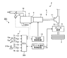
- FIG. 8 is a schematic configuration diagram of the vehicle control system according to the third embodiment
- FIG. 9 is a flowchart for explaining an example of control by the ECU
- FIG. 10 is a schematic diagram for explaining an E / G stop operation sequence in the free run only mode.
- FIG. 11 is a time chart for explaining an example of control by the ECU.
- the vehicle control device according to the third embodiment is different from the first embodiment in that it has a free run only mode instead of the free run utilization mode.
- the vehicle control system 301 of the present embodiment shown in FIG. 8 includes an ECU 308 as a vehicle control device, and the ECU 308 stops fuel consumption in the engine 4 in response to an operation on the shift lever 375a as a change operation member.
- control for changing the start mode of the engine 4 and the idle operation mode is executed.
- the shift lever 375a of the present embodiment can select a free-run dedicated range (free-run range) in addition to a parking range, a reverse range, a neutral range, a drive range, and the like as a shift range.
- the drive range is a range that allows the engine 4 to be started according to the brake operation (braking operation) on the vehicle 2 by the driver
- the free-run dedicated range is the engine 4 according to the brake operation on the vehicle 2 by the driver. This is a range that makes it impossible to start.
- the parking range, the reverse range, and the neutral range are also ranges in which the engine 4 can be started in accordance with a brake operation (braking operation) on the vehicle 2 by the driver.
- ECU308 determines whether or not the shift range is a free run dedicated range based on the detection result of the shift position sensor 75 (ST31).
- the ECU 308 determines that the shift range is not the free-run exclusive range (ST31: No), that is, when the deceleration eco-run mode is selected as the travel mode of the vehicle 2, the operation of the engine 4 is stopped, and the engine
- the deceleration eco-run E / G stop operation sequence is applied as an operation sequence for starting 4 (ST32), the current control cycle is terminated, and the next control cycle is started.
- the ECU 308 determines that the shift range is the free run dedicated range (ST31: Yes), that is, when the free run dedicated mode is selected as the travel mode of the vehicle 2, the operation of the engine 4 is stopped, and A free-run dedicated stop operation sequence is applied as an operation sequence for starting the engine 4 (ST33), the current control cycle is terminated, and the process proceeds to the next control cycle.
- the idle operation mode and the start mode of the engine 4 are set as an idle permission mode that enables the idle operation, and a start permission that allows the engine 4 to start according to the brake operation.
- the mode is set, and the operation of the engine 4 is stopped and the engine 4 is started in accordance with the deceleration eco-run E / G stop operation sequence illustrated in FIG. 3 described above.
- the idle operation mode and start mode of the engine 4 are set to the idle prohibition mode in which the idle operation is disabled, and the engine 4 cannot be started in response to the brake operation.
- the engine 4 is stopped and the engine 4 is started and stopped in accordance with the free-run dedicated stop operation sequence illustrated in FIG.
- the ECU 308 decomposes the vehicle state into two states, a state where the vehicle state can be estimated as “acceleration” and a state where the vehicle state can be estimated as “deceleration, steady state, or stopping” based on On / Off of the accelerator operation. Then, the transition is grasped, and the operation of the engine 4 is stopped and the engine 4 is started according to this.
- the ECU 308 operates the engine 4 when the accelerator operation is turned off (Acc-Off) in the state where the accelerator operation by the driver is On (Acc-On) in the free-run exclusive mode. Stop and execute idling stop.
- the accelerator operation by the driver is Off (Acc-Off) and the accelerator operation is On (Acc-On)
- the ECU 308 starts the engine 4 and puts it into an operating state.
- the free-run dedicated E / G stop operation sequence is applied, the ECU 308 directly links the accelerator operation On / Off and the start / stop of the engine 4 regardless of the brake operation or the like. That is, the ECU 308 starts and puts the engine 4 into an operating state when an accelerator operation is turned on by the driver, and stops the operation of the engine 4 and performs idling stop when the accelerator operation is turned off.
- the state where the accelerator operation by the driver is On is a state where it can be estimated that the vehicle state of the vehicle 2 is “acceleration”.
- the state where the accelerator operation by the driver is Off is a state where it can be estimated that the vehicle state of the vehicle 2 is “deceleration, steady state, or stop”.
- the vehicle control system 301 positively stops the operation of the engine 4 and performs idling stop, not only when the vehicle 2 decelerates and stops accompanying the brake operation. And free run can be used.
- the horizontal axis represents the time axis (time)
- the vertical axis represents the vehicle speed Vx
- the brake operation On / Off the accelerator operation On / Off
- the operating state of the engine (E / G) 4 the shift range.
- the ECU 308 turns off the accelerator operation at time t31, and the driver frees the shift range from the drive range by the shift lever 375a at time t32.
- a free-run dedicated E / G stop operation sequence (see FIG. 10) is applied as an operation sequence for stopping the operation of the engine 4 and starting the engine 4.
- ECU 308 stops the operation of engine 4 at time t32 and executes idling stop.
- the ECU 308 does not matter whether or not the driver performs the brake operation On / Off at times t33, t34, t35, t36, etc. during the period when the free-run exclusive range is selected as the shift range.
- the idle operation is prohibited, the engine 4 is stopped and the idling stop is continued. Then, when the driver turns on the accelerator operation at time t37, the ECU 308 generates an output that can start the engine 4 in accordance with this and set it in an operating state to realize a predetermined acceleration state according to the accelerator operation.
- the driver adjusts the speed by a predetermined operation, for example, a brake operation, during a free run in a state where the vehicle speed Vx is relatively high.
- a predetermined operation for example, a brake operation
- the vehicle control system 301 and the ECU 308 execute control to change the start mode of the engine 4 while the vehicle 2 is traveling, in which fuel consumption in the engine 4 is stopped, according to the operation of the shift lever 375a. Therefore, the vehicle control system 301 and the ECU 308 can clearly select the mode in which the engine 4 is started and the mode in which the engine 4 is not started according to the brake operation by the driver's intention by the driver's operation to the shift lever 375a. It can be. As a result, the vehicle control system 301 and the ECU 308 can select a mode with different engine start conditions by switching between a drive range or the like and a free run dedicated range, and can appropriately operate the driving state and fuel consumption reduction. It is possible to avoid the engine start after the speed adjustment by the brake operation and improve the fuel consumption by the intention of the person.
- the vehicle control device is not limited to the above-described embodiment, and various modifications can be made within the scope described in the claims.
- the vehicle control apparatus according to the present embodiment may be configured by combining a plurality of the embodiments described above.
- the first embodiment may be combined with the first embodiment.
- the vehicle described above may be a so-called “hybrid vehicle” provided with a motor generator as an electric motor capable of generating electricity in addition to the engine 4 as a driving power source.
- Vehicle control system Vehicle 3 Drive wheel 4 Engine (internal combustion engine) 5 Power transmission device 6 Brake device 7 State detection device 8, 208, 308 ECU (vehicle control device) 76 Free run utilization mode switch 217 Ambient environment information acquisition device 375a Shift lever (change operation member)
Abstract
Description
図1は、実施形態1に係る車両制御システムの概略構成図、図2は、ECUによる制御の一例を説明するフローチャート、図3は、減速エコランモードにおけるE/G停止操作シーケンスを説明する模式図、図4は、フリーラン活用モードにおけるE/G停止操作シーケンスを説明する模式図、図5は、ECUによる制御の一例を説明するタイムチャートである。
図6は、実施形態2に係る車両制御システムの概略構成図、図7はフリーラン活用モードにおけるE/G停止操作シーケンスを説明する模式図である。実施形態2に係る車両制御装置は、周辺環境情報に基づいて制御を実行する点で実施形態1とは異なる。その他、上述した実施形態と共通する構成、作用、効果については、重複した説明はできるだけ省略するとともに、同一の符号を付す(以下で説明する実施形態も同様である。)。
図8は、実施形態3に係る車両制御システムの概略構成図、図9は、ECUによる制御の一例を説明するフローチャート、図10は、フリーラン専用モードにおけるE/G停止操作シーケンスを説明する模式図、図11は、ECUによる制御の一例を説明するタイムチャートである。実施形態3に係る車両制御装置は、フリーラン活用モードにかえてフリーラン専用モードを有する点で実施形態1とは異なる。
2 車両
3 駆動輪
4 エンジン(内燃機関)
5 動力伝達装置
6 ブレーキ装置
7 状態検出装置
8、208、308 ECU(車両制御装置)
76 フリーラン活用モードスイッチ
217 周辺環境情報取得装置
375a シフトレバー(変更操作部材)
Claims (11)
- 車両の車速が予め設定される所定車速より低い場合に前記車両の駆動輪に作用させる動力を発生する内燃機関のアイドル運転を可能とし、前記車両の車速が前記所定車速以上である場合に前記内燃機関の前記アイドル運転を不能とする制御を実行することを特徴とする、
車両制御装置。 - 前記車両が加速走行する状態以外の状態であるときに、前記車両の車速が前記所定車速より低い場合に前記内燃機関の始動を可能とし、前記車両の車速が前記所定車速以上である場合に前記内燃機関の始動を不能とする制御を実行する、
請求項1に記載の車両制御装置。 - 前記内燃機関の始動のモードを、前記車両に対する制動操作を解除した際の前記車両の車速に応じて変更する制御を実行する、
請求項1に記載の車両制御装置。 - 前記内燃機関での燃料の消費を停止し当該車両を惰性で走行させる惰性走行中に、前記車両の車速が前記所定車速以上である場合に前記車両に対する制動操作に応じた前記内燃機関の始動を禁止する制御を実行する、
請求項1に記載の車両制御装置。 - 前記車両の周辺環境情報に基づいて、前記内燃機関の始動のモードを変更する制御を実行する、
請求項1乃至請求項4のいずれか1項に記載の車両制御装置。 - 前記内燃機関での燃料の消費を停止した前記車両の走行中の前記内燃機関の始動のモードを、変更操作部材への操作に応じて変更する制御を実行する、
請求項1に記載の車両制御装置。 - 前記変更操作部材は、シフトレンジとして、前記車両に対する制動操作に応じた前記内燃機関の始動を可能とするドライブレンジと、前記車両に対する制動操作に応じた前記内燃機関の始動を不能とするフリーランレンジとを選択可能である、
請求項6に記載の車両制御装置。 - 車両が加速走行する状態以外の状態であるときに、前記車両の車速が予め設定される所定車速より低い場合に前記車両の駆動輪に作用させる動力を発生する内燃機関の始動を可能とし、前記車両の車速が前記所定車速以上である場合に前記内燃機関の始動を不能とする制御を実行することを特徴とする、
車両制御装置。 - 車両の駆動輪に作用させる動力を発生する内燃機関の始動のモードを、前記車両に対する制動操作を解除した際の前記車両の車速に応じて変更する制御を実行することを特徴とする、
車両制御装置。 - 車両の駆動輪に作用させる動力を発生する内燃機関での燃料の消費を停止し当該車両を惰性で走行させる惰性走行中に、前記車両の車速が予め設定される所定車速以上である場合に前記車両に対する制動操作に応じた前記内燃機関の始動を禁止する制御を実行することを特徴とする、
車両制御装置。 - 車両の駆動輪に作用させる動力を発生する内燃機関での燃料の消費を停止した当該車両の走行中の前記内燃機関の始動のモードを、変更操作部材への操作に応じて変更する制御を実行することを特徴とする、
車両制御装置。
Priority Applications (6)
| Application Number | Priority Date | Filing Date | Title |
|---|---|---|---|
| EP11856601.7A EP2666995B1 (en) | 2011-01-21 | 2011-01-21 | Vehicle control device |
| CN201180065504.6A CN103328790B (zh) | 2011-01-21 | 2011-01-21 | 车辆控制装置 |
| JP2012553541A JP5590153B2 (ja) | 2011-01-21 | 2011-01-21 | 車両制御装置 |
| US13/979,985 US9422908B2 (en) | 2011-01-21 | 2011-01-21 | Vehicle control apparatus |
| PCT/JP2011/051130 WO2012098687A1 (ja) | 2011-01-21 | 2011-01-21 | 車両制御装置 |
| US14/816,966 US20150337789A1 (en) | 2011-01-21 | 2015-08-03 | Vehicle control apparatus |
Applications Claiming Priority (1)
| Application Number | Priority Date | Filing Date | Title |
|---|---|---|---|
| PCT/JP2011/051130 WO2012098687A1 (ja) | 2011-01-21 | 2011-01-21 | 車両制御装置 |
Related Child Applications (2)
| Application Number | Title | Priority Date | Filing Date |
|---|---|---|---|
| US13/979,985 A-371-Of-International US9422908B2 (en) | 2011-01-21 | 2011-01-21 | Vehicle control apparatus |
| US14/816,966 Continuation US20150337789A1 (en) | 2011-01-21 | 2015-08-03 | Vehicle control apparatus |
Publications (1)
| Publication Number | Publication Date |
|---|---|
| WO2012098687A1 true WO2012098687A1 (ja) | 2012-07-26 |
Family
ID=46515338
Family Applications (1)
| Application Number | Title | Priority Date | Filing Date |
|---|---|---|---|
| PCT/JP2011/051130 WO2012098687A1 (ja) | 2011-01-21 | 2011-01-21 | 車両制御装置 |
Country Status (5)
| Country | Link |
|---|---|
| US (2) | US9422908B2 (ja) |
| EP (1) | EP2666995B1 (ja) |
| JP (1) | JP5590153B2 (ja) |
| CN (1) | CN103328790B (ja) |
| WO (1) | WO2012098687A1 (ja) |
Cited By (3)
| Publication number | Priority date | Publication date | Assignee | Title |
|---|---|---|---|---|
| JP2014202158A (ja) * | 2013-04-08 | 2014-10-27 | 本田技研工業株式会社 | 車両用エンジン制御装置 |
| JP2016141164A (ja) * | 2015-01-29 | 2016-08-08 | トヨタ自動車株式会社 | 車両制御装置 |
| JP2017198139A (ja) * | 2016-04-27 | 2017-11-02 | マツダ株式会社 | 車両の制御装置 |
Families Citing this family (11)
| Publication number | Priority date | Publication date | Assignee | Title |
|---|---|---|---|---|
| US9422908B2 (en) * | 2011-01-21 | 2016-08-23 | Toyota Jidosha Kabushiki Kaisha | Vehicle control apparatus |
| US9535657B2 (en) * | 2011-04-05 | 2017-01-03 | Toyota Jidosha Kabushiki Kaisha | Vehicle and method for controlling vehicle |
| JP5857672B2 (ja) * | 2011-11-24 | 2016-02-10 | 日産自動車株式会社 | 車両のエンジン自動停止制御装置 |
| JP6082638B2 (ja) * | 2013-03-29 | 2017-02-15 | 日立オートモティブシステムズ株式会社 | 走行制御装置及び走行制御システム |
| JP6441716B2 (ja) * | 2015-03-17 | 2018-12-19 | ジヤトコ株式会社 | 車両制御装置、及び車両の制御方法 |
| US9932914B2 (en) * | 2015-04-14 | 2018-04-03 | Ford Global Technologies, Llc | Method for increasing electric operation in hybrid electric vehicles |
| JP6418062B2 (ja) * | 2015-05-19 | 2018-11-07 | トヨタ自動車株式会社 | 車速制御装置及び車両 |
| US10189453B2 (en) | 2016-10-05 | 2019-01-29 | Toyota Motor Engineering & Manufacturing North America, Inc. | Coasting guidance timing and drive force adjustment |
| US9896106B1 (en) | 2016-10-24 | 2018-02-20 | Toyota Motor Engineering & Manufacturing North America, Inc. | Coasting distance determination for coasting assistance system |
| US9898928B1 (en) | 2016-10-25 | 2018-02-20 | Toyota Motor Engineering & Manufacturing North America, Inc. | Coasting guidance timing and learning based on approach lane |
| JP6828391B2 (ja) * | 2016-11-16 | 2021-02-10 | スズキ株式会社 | エンジン再始動装置 |
Citations (3)
| Publication number | Priority date | Publication date | Assignee | Title |
|---|---|---|---|---|
| JP2004218544A (ja) * | 2003-01-15 | 2004-08-05 | Mazda Motor Corp | 車両のエンジン制御装置 |
| JP2010281301A (ja) * | 2009-06-08 | 2010-12-16 | Toyota Motor Corp | 内燃機関の制御装置 |
| JP2010285961A (ja) * | 2009-06-15 | 2010-12-24 | Denso Corp | 内燃機関の自動停止始動制御装置 |
Family Cites Families (26)
| Publication number | Priority date | Publication date | Assignee | Title |
|---|---|---|---|---|
| JPS5281436A (en) * | 1975-12-27 | 1977-07-07 | Nissan Motor Co Ltd | Air fuel ratio controller |
| IT1196693B (it) * | 1984-03-26 | 1988-11-25 | Fiat Auto Spa | Dispositivo stop start per il controllo del funzionamento del motore a combustione interna di un autoveicolo provvisto di cambio automatico |
| JPH0988651A (ja) * | 1995-09-29 | 1997-03-31 | Toyota Motor Corp | エンジンブレーキ力制御装置 |
| JP3890817B2 (ja) * | 1999-07-09 | 2007-03-07 | トヨタ自動車株式会社 | ハイブリッド車両の制御装置 |
| JP3213293B2 (ja) * | 1999-08-02 | 2001-10-02 | 本田技研工業株式会社 | エンジン制御装置 |
| KR20010028192A (ko) * | 1999-09-18 | 2001-04-06 | 배재철 | 차량의 급발진 제어장치 |
| US6376927B1 (en) * | 2000-01-18 | 2002-04-23 | Saturn Corporation | Hybrid electric drive and control method therefor |
| EP1227230B1 (en) * | 2001-01-26 | 2006-07-19 | Denso Corporation | Engine control apparatus |
| BR0205395A (pt) * | 2001-05-21 | 2003-06-17 | Luk Lamellen & Kupplungsbau | Processo de controle para veìculos automóveis com dispositivo de embreagem automatizado |
| JP4552365B2 (ja) * | 2001-06-27 | 2010-09-29 | 株式会社デンソー | エンジン自動停止再始動装置 |
| DE10307462B4 (de) * | 2003-02-21 | 2019-02-28 | Robert Bosch Gmbh | Verfahren zur Steuerung der Antriebseinheit eines Fahrzeugs |
| DE10331240A1 (de) * | 2003-07-10 | 2005-02-17 | Robert Bosch Gmbh | Verfahren und Steuergerät zur Steuerung eines Start-Stopp-Betriebs eines Verbrennungsmotors |
| JP4765487B2 (ja) * | 2005-08-29 | 2011-09-07 | 株式会社アドヴィックス | 車両用ブレーキ装置 |
| US7404784B2 (en) * | 2005-11-17 | 2008-07-29 | Autoliv Asp, Inc. | Fuel saving sensor system |
| JP2007187090A (ja) | 2006-01-13 | 2007-07-26 | Toyota Motor Corp | 速度維持制御装置 |
| CN1986309B (zh) * | 2006-12-08 | 2011-05-11 | 奇瑞汽车股份有限公司 | 一种混合动力汽车发动机启动控制方法 |
| JP4232825B2 (ja) * | 2007-01-12 | 2009-03-04 | トヨタ自動車株式会社 | 車両の制御装置 |
| FR2912187B1 (fr) * | 2007-02-07 | 2009-08-28 | Valeo Equip Electr Moteur | Procede de controle d'un systeme de demarrage / arret automatique d'un moteur thermique d'un vehicule, systeme correspondant et son utilisation |
| JP4730713B2 (ja) * | 2008-08-08 | 2011-07-20 | 株式会社デンソー | エンジン自動停止・始動制御装置 |
| JP4678442B2 (ja) * | 2009-03-12 | 2011-04-27 | 株式会社デンソー | 車両制御装置 |
| JP5398317B2 (ja) * | 2009-03-18 | 2014-01-29 | 株式会社エフ・シー・シー | 動力伝達装置 |
| US8795135B2 (en) * | 2009-09-01 | 2014-08-05 | Ford Global Technologies, Llc | Method for controlling an engine during a restart |
| US8401768B2 (en) * | 2009-09-01 | 2013-03-19 | Ford Global Technologies, Llc | System and method for restarting an engine |
| US8192327B2 (en) * | 2010-02-17 | 2012-06-05 | Ford Global Technologies, Llc | Methods and systems for assisted direct start control |
| US8574125B2 (en) * | 2010-12-30 | 2013-11-05 | Ford Global Technologies, Llc | Methods and systems for assisted direct start control |
| US9422908B2 (en) * | 2011-01-21 | 2016-08-23 | Toyota Jidosha Kabushiki Kaisha | Vehicle control apparatus |
-
2011
- 2011-01-21 US US13/979,985 patent/US9422908B2/en active Active
- 2011-01-21 EP EP11856601.7A patent/EP2666995B1/en active Active
- 2011-01-21 CN CN201180065504.6A patent/CN103328790B/zh not_active Expired - Fee Related
- 2011-01-21 JP JP2012553541A patent/JP5590153B2/ja active Active
- 2011-01-21 WO PCT/JP2011/051130 patent/WO2012098687A1/ja active Application Filing
-
2015
- 2015-08-03 US US14/816,966 patent/US20150337789A1/en not_active Abandoned
Patent Citations (3)
| Publication number | Priority date | Publication date | Assignee | Title |
|---|---|---|---|---|
| JP2004218544A (ja) * | 2003-01-15 | 2004-08-05 | Mazda Motor Corp | 車両のエンジン制御装置 |
| JP2010281301A (ja) * | 2009-06-08 | 2010-12-16 | Toyota Motor Corp | 内燃機関の制御装置 |
| JP2010285961A (ja) * | 2009-06-15 | 2010-12-24 | Denso Corp | 内燃機関の自動停止始動制御装置 |
Cited By (3)
| Publication number | Priority date | Publication date | Assignee | Title |
|---|---|---|---|---|
| JP2014202158A (ja) * | 2013-04-08 | 2014-10-27 | 本田技研工業株式会社 | 車両用エンジン制御装置 |
| JP2016141164A (ja) * | 2015-01-29 | 2016-08-08 | トヨタ自動車株式会社 | 車両制御装置 |
| JP2017198139A (ja) * | 2016-04-27 | 2017-11-02 | マツダ株式会社 | 車両の制御装置 |
Also Published As
| Publication number | Publication date |
|---|---|
| EP2666995A4 (en) | 2018-04-25 |
| EP2666995B1 (en) | 2020-03-25 |
| US20150337789A1 (en) | 2015-11-26 |
| JPWO2012098687A1 (ja) | 2014-06-09 |
| JP5590153B2 (ja) | 2014-09-17 |
| CN103328790B (zh) | 2016-04-20 |
| CN103328790A (zh) | 2013-09-25 |
| US9422908B2 (en) | 2016-08-23 |
| EP2666995A1 (en) | 2013-11-27 |
| US20130304358A1 (en) | 2013-11-14 |
Similar Documents
| Publication | Publication Date | Title |
|---|---|---|
| JP5590153B2 (ja) | 車両制御装置 | |
| JP5310942B2 (ja) | 車両制御装置及び車両制御システム | |
| JP5561231B2 (ja) | 車両制御システム | |
| RU2714698C2 (ru) | Система и контроллер для обеспечения медленного передвижения на электрической тяге в транспортном средстве с ручной коробкой передач | |
| JP5478572B2 (ja) | ハイブリッド車両の制御装置 | |
| JP5857672B2 (ja) | 車両のエンジン自動停止制御装置 | |
| JP2012214181A (ja) | 車両制御システム | |
| JP2012172578A (ja) | 車両制御装置 | |
| WO2017037760A1 (ja) | 車両走行制御方法及び車両走行制御装置 | |
| JP5575611B2 (ja) | エンジン自動停止再始動装置 | |
| JP2008179232A (ja) | ハイブリッド自動車 | |
| JP5228542B2 (ja) | ハイブリッド車両のモード切り替え制御装置 | |
| JP5549563B2 (ja) | 車両用制御装置 | |
| WO2011135679A1 (ja) | 発電制御装置及び発電制御システム | |
| JP2011221620A (ja) | 車両制御装置及び車両制御システム | |
| JP2001020775A (ja) | ハイブリッド車両の制御装置 | |
| WO2013125327A1 (ja) | エンジンの自動停止再始動制御装置 | |
| US9132822B2 (en) | Device and method for controlling clutch of hybrid vehicle | |
| JP6053099B2 (ja) | ハイブリッド車両の駆動制御装置 | |
| CN110462203B (zh) | 用于引起机动车的内燃机的自动的关断和/或接通过程的起停装置 | |
| JP6188110B1 (ja) | 自動車慣性走行制御システム。 | |
| JP2014172456A (ja) | アイドルストップ車の制御装置 | |
| JP2019031153A (ja) | 走行制御装置、車両および走行制御方法 | |
| KR20120082623A (ko) | 하이브리드 차량의 후진 주행 중 직진 변속 시에 대한 변속 제어 방법 | |
| JP2014114771A (ja) | 車両の電力制御装置 |
Legal Events
| Date | Code | Title | Description |
|---|---|---|---|
| WWE | Wipo information: entry into national phase |
Ref document number: 201180065504.6 Country of ref document: CN |
|
| 121 | Ep: the epo has been informed by wipo that ep was designated in this application |
Ref document number: 11856601 Country of ref document: EP Kind code of ref document: A1 |
|
| ENP | Entry into the national phase |
Ref document number: 2012553541 Country of ref document: JP Kind code of ref document: A |
|
| WWE | Wipo information: entry into national phase |
Ref document number: 13979985 Country of ref document: US |
|
| WWE | Wipo information: entry into national phase |
Ref document number: 2011856601 Country of ref document: EP |
|
| WWE | Wipo information: entry into national phase |
Ref document number: 1301004055 Country of ref document: TH |
|
| NENP | Non-entry into the national phase |
Ref country code: DE |