WO2012090445A1 - 1柱1杭基礎構造 - Google Patents
1柱1杭基礎構造 Download PDFInfo
- Publication number
- WO2012090445A1 WO2012090445A1 PCT/JP2011/007162 JP2011007162W WO2012090445A1 WO 2012090445 A1 WO2012090445 A1 WO 2012090445A1 JP 2011007162 W JP2011007162 W JP 2011007162W WO 2012090445 A1 WO2012090445 A1 WO 2012090445A1
- Authority
- WO
- WIPO (PCT)
- Prior art keywords
- pile
- foundation structure
- pile foundation
- concrete
- pillar
- Prior art date
- Legal status (The legal status is an assumption and is not a legal conclusion. Google has not performed a legal analysis and makes no representation as to the accuracy of the status listed.)
- Ceased
Links
Images






Classifications
-
- E—FIXED CONSTRUCTIONS
- E02—HYDRAULIC ENGINEERING; FOUNDATIONS; SOIL SHIFTING
- E02D—FOUNDATIONS; EXCAVATIONS; EMBANKMENTS; UNDERGROUND OR UNDERWATER STRUCTURES
- E02D5/00—Bulkheads, piles, or other structural elements specially adapted to foundation engineering
- E02D5/22—Piles
- E02D5/223—Details of top sections of foundation piles
-
- E—FIXED CONSTRUCTIONS
- E02—HYDRAULIC ENGINEERING; FOUNDATIONS; SOIL SHIFTING
- E02D—FOUNDATIONS; EXCAVATIONS; EMBANKMENTS; UNDERGROUND OR UNDERWATER STRUCTURES
- E02D27/00—Foundations as substructures
- E02D27/10—Deep foundations
- E02D27/12—Pile foundations
Definitions
- the present invention relates to a 1 pillar 1 pile foundation structure used for a foundation of a building or the like.
- a 1-pillar 1-pile foundation structure used for the foundation of buildings, etc., it is equipped with a pile that is buried (or placed) in the ground and a steel pipe (joint) that is arranged vertically above this pile. Is known.
- FIG. That is, a pile, a column base, and the junction part which connects these piles and a column base are each carried in a construction site as a separate body. And after embedding a pile in the ground of a predetermined position, a joint part is mounted on the pile head part of this pile, and after making the core of a pile and the core of a joint part correspond, a pile and a junction part are integrated. After that, insert the tip of the column base into the internal space of the joint through the open end of the joint, adjust the vertical and horizontal positions of the column base, and then fill and solidify the concrete inside the joint. Thus, the pile and the column base are joined via concrete.
- the pile, the joint, and the column base are carried into the construction site as separate members, so that the carrying-in operation can be simplified.
- the pile, joint, and column base are carried into the construction site as separate members, and these members align the core of the pile with the core of the joint, and adjust the vertical and horizontal position of the column base. Therefore, even if the pile is press-fitted (embedded) at a location deviated from the predetermined position, the pile placement error can be absorbed by adjusting the position of the column base and the strength of the joint is reduced.
- the pillar can always be installed at a predetermined position without causing it.
- an object of the present invention is to provide a one-column / one-pile foundation structure that can maintain its function without a sudden decrease in the yield strength of concrete even when an excessive pulling force is applied.
- the 1 pillar 1 pile foundation structure of this invention is comprised by a pile, a junction part, and a column base.
- the pile is buried in the ground.
- a joint part is a cylindrical part which is arrange
- the column base includes a base plate at a lower end, and a joining region including the base plate is inserted into a cavity of the joining portion and joined to the pile through concrete.
- the 1 pillar 1 pile foundation structure of this invention is equipped with a slip prevention body, It is characterized by the above-mentioned. This slip prevention body is provided to project inward at a predetermined position in the height direction of the joint.
- the slip prevention body is provided above a position T where a virtual straight line L extending in the direction of an elevation angle of 45 ° from the horizontal end of the base plate intersects the inner wall of the joint (Requirement 1).
- the one-column / one-pile foundation structure of the present invention has a concrete bearing strength of Pn by a detent body, and a cone-shaped fracture strength of the whole concrete (hereinafter also referred to as filled concrete) filled in the cavity Ps. Then, it is configured to satisfy Pn> Ps (requirement 2).
- the 1 pillar 1 pile foundation structure of the present invention is provided with the requirement 2, and the breakage of the bearing portion by the slip prevention body is prioritized over the cone-shaped breakage, so that it is possible to avoid a sudden decline in the proof stress.
- Pn and Ps are obtained, for example, as follows, and elements that specify Pn and Ps may be adjusted so as to satisfy Pn> Ps.
- a baseplate to the downward end part of a junction part.
- a force is also applied in the horizontal direction to the one-pile and one-pile foundation structure where excessive shaking occurs due to an earthquake or the like.
- the bottom plate resists this horizontal force and prevents the lower end of the joint from being deformed into an ellipse (hereinafter referred to as oval deformation).
- the bottom plate may be solid, but preferably includes a hollow portion. Residual stress occurs when the bottom plate is fixed to the lower end of the joint by welding, but this residual stress is released by providing a hollow portion.
- a flange projecting outward is fixed to the upper end of the joint. This flange prevents the oval deformation at the upper end of the joint.
- the projecting portion When the flange is provided at the uppermost end of the joint, when the flange is projected inward, the projecting portion can be functioned as a stopper. In this case, a single member can exert two functions of preventing slippage and preventing elliptic deformation.
- the anti-slip body restrains the upward force applied to the portion inside the imaginary straight line L, so that cone-like fracture along the elevation angle of 45 ° occurs in the filled concrete.
- the destruction of the bearing portion in the slip prevention body is prioritized over the cone-like destruction, it is possible to avoid a sudden decrease in yield strength.
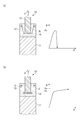
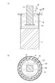
- FIG. 1 shows a first embodiment of a one-column / one-pile foundation structure according to the present invention, where (a) is a sectional side view, (b) is a sectional view taken along arrow 1b-1b in (a), and (c) is 1b in (a). It is sectional drawing of the location corresponded to -1b arrow cross section. It is a figure for demonstrating the construction process of the 1 pillar 1 pile foundation structure by 1st Embodiment. It is a figure for demonstrating the requirement 2 of the 1 pillar 1 pile foundation structure by 1st Embodiment. It is a figure which shows the example of a change of the 1 pillar 1 pile foundation structure by 1st Embodiment.
- the 1 pillar 1 pile foundation structure 10 which concerns on this embodiment is the pile 11 embed
- the column base 13 joined to the pile 11 via the filling concrete 14 in the joining unit 12 is configured as a main element.
- the positional relationship such as up / down, vertical / horizontal, etc. is based on the state in which the one pillar / one pile foundation structure 10 is installed.
- the pile 11 can be made of steel or concrete.
- a steel pile having a wing (not shown) at the tip (the lower end in FIG. 1A), press-fitting until the tip reaches a support layer (not shown). It is press-fitted into the ground G by a machine or the like.
- the joining unit 12 includes a hollow cylindrical unit body 121 (for example, a steel pipe) having substantially the same outer diameter as the pile 11, and both the upper end and the lower end of the unit body 121 are opened.
- the unit main body 121 is provided with a displacement preventing body 122 projecting inward on the inner wall 12X.
- the slip prevention body 122 has a ring shape, and is manufactured by punching a steel plate, for example.
- the slip stopper 122 includes an inner peripheral edge 122X and an outer peripheral edge 122Y.
- the displacement preventing body 122 is fixed to the unit main body 121 by welding the outer peripheral edge 122 ⁇ / b> Y and the inner wall 12 ⁇ / b> X of the joining unit 12.
- the present embodiment is characterized by the position where the displacement preventing body 122 is provided in the unit main body 121, which will be described later.
- the steel pipe pile 11 and the joining unit 12 are fixed by welding. However, this fixing is not limited to this, and it can also be fixed via an attachment plate and bolts and nuts.
- the pile 11 is made of concrete, the upper end is exposed from the pile head.
- a reinforcing bar is embedded in the pile 11, and the joining unit 12 can be fixed to the pile 11 through this reinforcing bar and filled concrete 14 described later.
- the tip end portion (lower end portion in FIG. 1) of the column base 13 having a rectangular cross section is inserted, and the joining unit 12 and the column base 13 are inserted.
- a base plate 131 is provided at the lowermost end of the column base 13. The base plate 131 is disposed along the horizontal direction.
- the base plate 131 is a reference for the position at which the stopper 122 is provided. That is, as shown in FIG. 1, a straight line (virtual straight line L) drawn from the end of the base plate 131 upward 45 ° (elevation angle 45 °) with respect to the horizontal direction is drawn. A point that intersects the 12 inner walls is defined as a position T. Then, the slip prevention body 122 is provided above the position T. In addition, when the column base 13 is a rectangle, the virtual straight line L in the plane direction is drawn in a direction perpendicular to the middle point of the side.
- FIG. 1A After digging a hole 15 in the ground G at a predetermined position where the pile 11 is to be embedded, and setting the pile 11 in the hole 15, it is not shown until the tip of the pile 11 reaches the support layer in the ground G.
- a rotary press-fitting is performed using a press-fitting machine or the like (FIG. 2A).
- the joining unit 12 is placed on the pile head of the pile 11, the core of the pile 11 and the core of the joining unit 12 are matched, and then the pile 11 and the joining unit 12 are fixed by welding.
- the hole 15 is backfilled, and only the opening end of the joining unit 12 is exposed from the surface of the ground G (FIG. 2B).
- the backfilling of the holes 15 may be performed after completion of a series of operations until the column base is fixed. Then, the tip of the column base 13 is inserted into the cavity C of the joining unit 12 through the opening end of the joining unit 12, and the core of the joining unit 12 and the core of the column base 13 are made to coincide by using a positioning device or the like. (See FIG. 2 (c)). In this state, filling concrete 14 is filled into the internal space of the joining unit 12, and the joining unit 12 and the column base 13 are joined. The construction is completed (see FIG. 2D and FIGS. 1A and 1B). ).
- the one-column / one-pile foundation structure 10 constructed as described above is characterized in that the displacement preventing body 122 is provided above the position T (requirement 1). Moreover, the 1 pillar 1 pile foundation structure 10 sets the area An of the slip prevention body 122 so that the following formula
- Ps cone-like fracture strength of the entire filled concrete 14
- the stopper 122 can restrain the upward force applied to the portion inside the virtual straight line L. Therefore, in this case, it is possible to prevent the fracture of the filled concrete 14 from breaking out like a cone along the virtual straight line L.
- Pn and Ps can be defined as follows.
- Pn Conscrete bearing strength by slip stopper 122
- Pn An ⁇ fn ⁇ N
- An Area per step of the stopper body 122 (surface area of one surface of the stopper body 122)
- fn Maximum bearing stress of concrete
- N Number of steps of the displacement preventing body 122 provided above the position T (one step in the first embodiment)
- fn can be obtained as follows.
- Ps Cone-like fracture strength of the entire filled concrete
- Ps As ⁇ fs As: Area of cone fracture surface (area of inclined side surface excluding top and bottom surfaces of truncated cone formed by fracture)
- fs Fracture strength of concrete on cone fracture surface
- the 1 pillar 1 pile foundation structure 10 of this embodiment has the relationship of Pn> Ps, as shown in FIG.3 (b), rather than the bearing part Z by the slip prevention body 122, ie, the slip prevention body 122, it is.
- the destruction of the priority concrete 14 located on the lower side occurs in preference to the destruction along the destruction line DL.
- the stress-strain diagram of the filled concrete 14 in the one-column / one-pile foundation structure 10 shows that the filled concrete 14 located below the stopper body 122 is supported as shown in FIG. Since it is gradually destroyed by pressure, it does not show a sudden decline in yield strength. Therefore, it can be said that the 1 pillar 1 pile foundation structure 10 is a sticky structure.
- this 1 pillar 1 pile foundation structure 10 provides only one slip prevention body 122
- the present invention can provide a plurality of stages of slip prevention bodies 122.
- at least one displacement preventing body 122 is provided above the position T, even if the displacement preventing body 122 is provided below the position T, it does not depart from the scope of the present invention. Absent.
- the ring-shaped form shown in FIGS. 1A and 1B is merely an example of the slip preventing body 122, and any form can be used as long as it meets the purpose.
- the half-moon-shaped slip prevention body 122 can also be used.
- the slip stopper 122 can be cut out in a part in the circumferential direction. Since the shift stopper 122 can adjust the diameter of the shift stopper 122 by the amount of the notch, it can be elastically inserted into the joining unit 12.
- step difference S is provided in the inner wall 12X of the joining unit 12, and the periphery of the slip prevention body 122 is mounted and supported on this level
- the step S is formed at an arbitrary position above the position T. If it does as above, while positioning of the slip prevention body 122 is easy, since the slip prevention body 122 is supported in the height direction, the work burden welded to the inner wall 12X can be reduced.
- FIGS. A second embodiment of a one-column / one-pile foundation structure according to the present invention will be described with reference to FIGS.
- the 1 pillar 1 pile foundation structure 20 in 2nd Embodiment differs from the thing of 1st Embodiment mentioned above by the point that the joining unit 22 is provided instead of the joining unit 12.
- FIG. Since other components are the same as those in the first embodiment, description of these components is omitted here.
- symbol is attached
- a steel bottom plate 123 is fixed to the lower end of the unit main body 121 so as to close the opening of the one pillar / one pile foundation structure 20.
- the bottom plate 123 is a disk-shaped member.
- the bottom plate 123 is inserted inside the unit main body 121 so as to be flush with the lower opening end of the unit main body 121. In this state, the bottom plate 123 is fixed to the unit main body 121 by welding.
- the operation and effect of the bottom plate 123 will be described.
- an excessive shaking occurs due to an earthquake or the like, force is applied to the one pillar / one pile foundation structure 10 in the horizontal direction in addition to the vertical direction.
- a force is applied to the joining unit 22 in the radial direction, and the joining unit 22 may be distorted in the horizontal direction.
- the joining unit 22 is circular, this horizontal distortion appears as an oval deformation in the joining unit 22.
- the bottom plate 123 is provided as a stiffening member that prevents oval deformation at the lower end of the joining unit 22.
- the bottom plate 123 functions as a stiffening member that prevents the unit main body 121 of the joining unit 22 from being deformed into an ellipse, and prevents a sudden decrease in yield strength even in the final state.
- FIG. 6 (a) corresponds to the design value, (b) corresponds to the second embodiment, and (c) corresponds to the case where the bottom plate 123 is not provided.
- the bottom plate 123 prevents the joint unit 22 from being deformed in an oval.
- the proof stress at the portion does not decrease and satisfies the design value.
- the bottom plate 123 is not provided, if the concrete in the joining unit is damaged, the joining unit is deformed into an ellipse, and the yield strength is drastically reduced.
- the joining unit 22 described above is a solid disk-shaped member of the bottom plate 123, but the present invention is not limited to this as long as it has a function of preventing the unit main body 121 from being deformed into an oval.
- a ring-shaped bottom plate 124 is preferable.
- the bottom plate 124 is fixed to the unit main body 121 by welding. After welding, residual stress (thermal stress) is generated in the unit main body 121 and the bottom plate 124. This thermal stress also acts in the radial direction of the unit main body 121 and the bottom plate 124.
- the ring-shaped bottom plate 124 is provided with the hollow portion E, the thermal stress is released by the hollow portion E. Therefore, the joining unit 22 shown in FIG. 7 can reduce deformation caused by thermal stress.
- the ring-shaped bottom plate 124 When the ring-shaped bottom plate 124 is used, there is a possibility that the filled concrete 14 leaks to the outside from the central gap. Therefore, in this embodiment, it is preferable to place a disk-shaped lid 125 on the bottom plate 124 so as to cover the gap.
- the ring-shaped bottom plate 124 having a circular gap is shown here, the shape of the hollow portion E is not limited to a circular shape. Even in the case of triangular, rectangular or other polygonal voids, the thermal stress can be released.
- FIG.8 and FIG.9 3rd Embodiment of the 1 pillar 1 pile foundation structure by this invention is described using FIG.8 and FIG.9.
- the 1 pillar 1 pile foundation structure 30 in 3rd Embodiment differs from the thing of 1st Embodiment mentioned above by the point that the joining unit 32 is provided instead of the joining unit 12.
- FIG. Since other components are the same as those in the first embodiment, description of these components is omitted here.
- symbol is attached
- a ring-shaped member 126 is fixed to the upper opening end of the unit main body 121 by welding, for example.
- the outer diameter of the ring-shaped member 126 is larger than the outer diameter of the unit main body 121.
- This portion constitutes the flange 127. Therefore, the one pillar / one pile foundation structure 30 can function as a stiffening member that prevents an oval deformation at the upper end of the joining unit main body 121.
- the inner diameter of the ring-shaped member 125 is smaller than the inner diameter of the unit main body 121. This portion functions as a slip prevention body 122.
- the one-pillar-one-pile foundation structure 30 has one ring-shaped member 126 having an inner diameter smaller than the inner diameter of the unit body 121 and an outer diameter larger than the outer diameter of the unit body 121.
- the member can have both of the functions of preventing the slippage of the filling concrete 14 and the function as a stiffening member for preventing the unit body 121 from being overly deformed.
- a bottom plate 129 can be fixed to the lower end of the unit main body 121 by welding in order to prevent the lower end portion of the joining unit main body 121 from being deformed into an ellipse. By doing so, it is possible to prevent the unit main body 121 from being deformed into an ellipse from the upper end to the lower end. 8 and 9, the flange 127 and the displacement preventing body 122 are integrally formed.
- the displacement preventing body 122 may be a separate body as shown in FIG. 10. In this case, the position at which the slip prevention body 122 is provided is not limited to the upper opening end of the unit main body 121, but may be a position that satisfies the requirement 1 described above.
- the pile 11 used by this invention is made of steel as described so far. It is not limited to a pile (steel pipe pile), and may be a reinforced concrete (RC) reinforced pile, that is, a cast-in-place concrete pile.
- RC reinforced concrete
- the joining unit 12 may be configured such that its cross-sectional shape has a rectangle (for example, a rectangle).
- a rectangle for example, a rectangle.
- FIG. 1 pile foundation structure was explained. However, this invention is applicable about the 1 pillar 1 pile foundation structure of the form with which the part corresponded to the joining unit 12 is integrated in the pile 11 as a pile head.
Landscapes
- Engineering & Computer Science (AREA)
- Structural Engineering (AREA)
- Life Sciences & Earth Sciences (AREA)
- General Life Sciences & Earth Sciences (AREA)
- Mining & Mineral Resources (AREA)
- Paleontology (AREA)
- Civil Engineering (AREA)
- General Engineering & Computer Science (AREA)
- Foundations (AREA)
- Piles And Underground Anchors (AREA)
Abstract
過大な引抜力が作用しても、コンクリートの耐力が急激に低下することなく、その機能を保持できる1柱1杭基礎構造を提供する。 杭11と、充填コンクリート14を収容するキャビティCを有する接合ユニット12と、ベースプレート131を含む接合領域が充填コンクリート14を介して杭11と接合される柱脚13と、を備える。接合ユニット12の高さ方向の所定位置に内方に張り出すずれ止め体122と、を備える。ずれ止め体122は、ベースプレート131の水平方向の端部より仰角45°の向きに延びる仮想直線Lがユニット本体121の内壁と交差する位置Tよりも上方に設けられる。また、ずれ止め体122によるコンクリート支圧強度をPn、充填コンクリート14全体のコーン状の破壊強度をPs、とすると、ずれ止め体122の面積Anが、Pn>Psを満足するように形成される。
Description
本発明は、建築物等の基礎に用いられる1柱1杭基礎構造に関するものである。
建築物等の基礎に用いられる1柱1杭基礎構造としては、地盤中に埋設される(あるいは打設される)杭と、この杭の鉛直上方に配置される鋼管(接合部)とを備えたものが知られている。
その中で、本発明者等は特許文献1において以下の1柱1杭基礎構造の施工方法を提案した。すなわち、杭、柱脚、およびこれら杭と柱脚とを連結する接合部を、それぞれ別体として施工現場に搬入する。そして、所定位置の地盤中に杭を埋設した後に、この杭の杭頭部に接合部を載せ、杭の芯と接合部の芯とを一致させてから杭と接合部とを一体化する。その後、接合部の開口端を通して、柱脚の先端部を接合部の内部空間内に挿入し、柱脚の鉛直方向および水平方向の位置を調整後、接合部の内部にコンクリートを充填、固化することで、杭と柱脚とをコンクリートを介して接合する。
以上の施工方法によると、杭、接合部、および柱脚が、それぞれ別部材として施工現場に搬入されることとなるので、搬入作業の簡略化を図ることができる。また、杭、接合部、および柱脚が、それぞれ別部材として施工現場に搬入され、これら部材は、杭の芯と接合部の芯とを一致させ、柱脚の鉛直方向および水平方向の位置調整を行うように組み立てられるため、杭が所定位置からずれた場所に圧入(埋設)されたとしても、柱脚の位置調整により杭の打設誤差を吸収することができ、接合部の強度を低下させることなく常に所定位置に柱を設置することができる。
以上の施工方法によると、杭、接合部、および柱脚が、それぞれ別部材として施工現場に搬入されることとなるので、搬入作業の簡略化を図ることができる。また、杭、接合部、および柱脚が、それぞれ別部材として施工現場に搬入され、これら部材は、杭の芯と接合部の芯とを一致させ、柱脚の鉛直方向および水平方向の位置調整を行うように組み立てられるため、杭が所定位置からずれた場所に圧入(埋設)されたとしても、柱脚の位置調整により杭の打設誤差を吸収することができ、接合部の強度を低下させることなく常に所定位置に柱を設置することができる。
1柱1杭基礎構造は、コンクリートを介して柱脚からの荷重を杭に伝達するが、地震等で過大な引抜力が柱脚に作用した際に、コンクリートが破壊してコーン状に抜け出てしまうとコンクリートの耐力が急激に低下して、1柱1杭基礎構造としての機能が失われてしまう。しかしながら、特許文献1は、この観点からの検討が十分に加えられていなかった。
そこで本発明は、過大な引抜力が作用しても、コンクリートの耐力が急激に低下することなく、その機能を保持できる1柱1杭基礎構造を提供することを目的とする。
そこで本発明は、過大な引抜力が作用しても、コンクリートの耐力が急激に低下することなく、その機能を保持できる1柱1杭基礎構造を提供することを目的とする。
本発明の1柱1杭基礎構造は、杭と、接合部と、柱脚により構成される。
杭は、地中に埋設される。
接合部は、杭の杭頭部に配設され、コンクリートが充填されるキャビティを有する筒状の部分である。
柱脚は、下端にベースプレートを備え、ベースプレートを含む接合領域が、接合部のキャビティ内に挿入され、コンクリートを介して杭と接合される。
本発明の1柱1杭基礎構造は、ずれ止め体を備えることを特徴とする。このずれ止め体は、接合部の高さ方向の所定位置に内方に張り出して設けられる。また、ずれ止め体は、ベースプレートの水平方向の端部より仰角45°の向きに延びる仮想直線Lが接合部の内壁と交差する位置Tよりも上方に設けられる(要件1)。
さらに、本発明の1柱1杭基礎構造は、ずれ止め体によるコンクリート支圧強度をPn、キャビティ内に充填されるコンクリート(以下、充填コンクリートということがある)全体のコーン状の破壊強度をPsとすると、Pn>Psを満足するように構成される(要件2)。
杭は、地中に埋設される。
接合部は、杭の杭頭部に配設され、コンクリートが充填されるキャビティを有する筒状の部分である。
柱脚は、下端にベースプレートを備え、ベースプレートを含む接合領域が、接合部のキャビティ内に挿入され、コンクリートを介して杭と接合される。
本発明の1柱1杭基礎構造は、ずれ止め体を備えることを特徴とする。このずれ止め体は、接合部の高さ方向の所定位置に内方に張り出して設けられる。また、ずれ止め体は、ベースプレートの水平方向の端部より仰角45°の向きに延びる仮想直線Lが接合部の内壁と交差する位置Tよりも上方に設けられる(要件1)。
さらに、本発明の1柱1杭基礎構造は、ずれ止め体によるコンクリート支圧強度をPn、キャビティ内に充填されるコンクリート(以下、充填コンクリートということがある)全体のコーン状の破壊強度をPsとすると、Pn>Psを満足するように構成される(要件2)。
コンクリートに引張りが作用すると、その作用した方向に対して45°の方向に沿って最も破壊しやすい。本発明の1柱1杭基礎構造によると、要件1により、ずれ止め体が仮想直線Lよりも内側の部分に加わる上向き(鉛直)の力に対抗して当該内側の部分が上向きにずれるのを拘束する。したがって、本発明によると、充填コンクリートに45°の方向に沿って生じやすいコーン状の破壊を防止できる。
また、45°の方向の破壊を避けることができたとしても、ベースプレートの水平方向の端部より仰角45°を超える範囲でコーン状の破壊が生ずるおそれがある。ところが本発明の1柱1杭基礎構造は、要件2を備えることに、ずれ止め体による支圧部分の破壊がコーン状の破壊よりも優先して生じるので、急激な耐力低下を避けることができる。
ここで、Pn、Psは例えば以下により求められるものとし、Pn>Psを満足するようにPn、Psを特定する要素を調整すればよい。
Pn=An×fn×N…式(1)
An:ずれ止め一段当りの面積、fn:コンクリートの最大支圧応力
N:位置Tよりも上側に設けられるずれ止め体の段数
Ps=As×fs…式(2)
As:コーン破壊面の表面積
fs:コーン破壊面におけるコンクリートの破壊強度
なお、Pn、Psについては、他の計算式、例えば、実験式が存在しうる。
また、45°の方向の破壊を避けることができたとしても、ベースプレートの水平方向の端部より仰角45°を超える範囲でコーン状の破壊が生ずるおそれがある。ところが本発明の1柱1杭基礎構造は、要件2を備えることに、ずれ止め体による支圧部分の破壊がコーン状の破壊よりも優先して生じるので、急激な耐力低下を避けることができる。
ここで、Pn、Psは例えば以下により求められるものとし、Pn>Psを満足するようにPn、Psを特定する要素を調整すればよい。
Pn=An×fn×N…式(1)
An:ずれ止め一段当りの面積、fn:コンクリートの最大支圧応力
N:位置Tよりも上側に設けられるずれ止め体の段数
Ps=As×fs…式(2)
As:コーン破壊面の表面積
fs:コーン破壊面におけるコンクリートの破壊強度
なお、Pn、Psについては、他の計算式、例えば、実験式が存在しうる。
本発明の1柱1杭基礎構造において、接合部の下方端部に底板を固定することが好ましい。
地震等で過大な揺れが生じる、1柱1杭基礎構造には鉛直方向に加えて水平方向にも力が加わる。底板は、この水平方向の力に対抗して、接合部の下方端部が楕円に変形する(以下、オーバルな変形という)のを防止する。
地震等で過大な揺れが生じる、1柱1杭基礎構造には鉛直方向に加えて水平方向にも力が加わる。底板は、この水平方向の力に対抗して、接合部の下方端部が楕円に変形する(以下、オーバルな変形という)のを防止する。
この底板は、中実であってもよいが、中空部を備えることが好ましい。
底板を接合部の下方端部に溶接で固定すると残留応力が生じるが、中空部を設けることでこの残留応力を開放する。
底板を接合部の下方端部に溶接で固定すると残留応力が生じるが、中空部を設けることでこの残留応力を開放する。
本発明の1柱1杭基礎構造において、接合部の上方端部に外方に張り出すフランジが固定されていることが好ましい。このフランジは、接合部の上方端部にオーバルな変形が生ずるのを防止する。
このフランジを接合部の最上端に設けることが、接合部の上方端部のオーバルな変形を最も効果的に防止することができる。
フランジが接合部の最上端に設けられる場合、フランジを内方に張り出させると、張り出し部分をずれ止め体として機能させることができる。この場合、1つの部材で、ずれ止めと楕円変形防止の2つの機能を発揮できる。
本発明の1柱1杭基礎構造によると、ずれ止め体が仮想直線Lよりも内側の部分に加わる上向きの力を拘束するので、仰角45°に沿ったコーン状の破壊が充填コンクリートに生じるのを防止できるとともに、ずれ止め体における支圧部分の破壊がコーン状の破壊よりも優先して生じるので、急激な耐力低下を避けることができる。
<第1実施形態>
以下、本発明による1柱1杭基礎構造の第1実施形態を、図1~図3を参照しながら説明する。
本実施形態に係る1柱1杭基礎構造10は、地盤G(図2)に埋設され又は打設される杭11と、この杭11の鉛直上方に配置された接合ユニット(接合部)12と、接合ユニット12内の充填コンクリート14を介して杭11と接合される柱脚13と、を主たる要素として構成されたものである。なお、上・下、鉛直・水平などの位置関係は、1柱1杭基礎構造10が設置された状態を基準にする。
以下、本発明による1柱1杭基礎構造の第1実施形態を、図1~図3を参照しながら説明する。
本実施形態に係る1柱1杭基礎構造10は、地盤G(図2)に埋設され又は打設される杭11と、この杭11の鉛直上方に配置された接合ユニット(接合部)12と、接合ユニット12内の充填コンクリート14を介して杭11と接合される柱脚13と、を主たる要素として構成されたものである。なお、上・下、鉛直・水平などの位置関係は、1柱1杭基礎構造10が設置された状態を基準にする。
杭11は、鋼製又はコンクリート製のものを使用することができる。例えば、先端部(図1(a)において下側の端部)に翼(図示せず)を有する鋼製の杭の場合、その先端部が支持層(図示せず)に到達するまで、圧入機等により地盤G中に回転圧入されている。
接合ユニット12は、杭11と略同じ外径を有する中空円筒状のユニット本体121(例えば、鋼管)を備え、ユニット本体121の上端及び下端ともに開口されている。ユニット本体121には、その内壁12Xに内方に向けて張り出しているずれ止め体122が設けられている。ずれ止め体122は、リング状の形態をなしており、例えば鋼板を打ち抜いて作製される。ずれ止め体122は、内周縁122Xと外周縁122Yを備える。外周縁122Yと接合ユニット12の内壁12Xが溶接されることで、ずれ止め体122はユニット本体121に固定される。本実施形態は、ずれ止め体122がユニット本体121に設けられる位置に特徴を有しているが、この点については後述する。
鋼管製の杭11と接合ユニット12とは、溶接により固定される。ただし、この固定はこれに限るものではなく、添接板及びボルト・ナットを介して固定することもできるし、杭11がコンクリート製の場合には、杭頭部から上端が露出されるように鉄筋を杭11に埋設し、この鉄筋と後述する充填コンクリート14を介して杭11に接合ユニット12を固定できる。
接合ユニット12の内部の空間であるキャビティCには、断面が例えば矩形状の柱脚13の先端部(図1において下側の端部)が挿入されており、これら接合ユニット12と柱脚13とは、接合ユニット12のキャビティCに充填された充填コンクリート14を介して接合されている。柱脚13の最下端には、ベースプレート131が設けられている。ベースプレート131は、水平方向に沿って配置される。
ベースプレート131は、ずれ止め体122を設ける位置の基準となる。つまり、図1に示すように、ベースプレート131の端部より水平方向に対して45°上向き(仰角45°)に引出される直線(仮想直線L)を描くものとし、この仮想直線Lが接合ユニット12の内壁と交差する点を位置Tとする。そうすると、ずれ止め体122は、位置Tよりも上に設けられる。なお、柱脚13が矩形の場合、平面方向における仮想直線Lは、辺の中間点から垂直な方向に引き出すものとする。
つぎに、本実施形態に係る1柱1杭基礎構造10の施工方法について図2を参照しながら説明する。
まず、杭11を埋設しようとする所定位置の地盤Gに穴15を掘り、その穴15に杭11を立てた後、杭11の先端部が地盤G中の支持層に到達するまで、図示しない圧入機等を用いて回転圧入する(図2(a))。
次いで、杭11の杭頭部に接合ユニット12を載せ、杭11の芯と接合ユニット12の芯とを一致させた後、杭11と接合ユニット12とを溶接により固定する。杭11と接合ユニット12との固定が完了したら穴15を埋め戻し、接合ユニット12の開口端のみを地盤Gの表面から露出させる(図2(b))。なお、穴15の埋め戻しは、柱脚固定までの一連の作業完了後に行ってもよい。
そして、接合ユニット12の開口端を通して、柱脚13の先端部を接合ユニット12のキャビティC内に挿入し、位置決め装置を用いるなどして接合ユニット12の芯と柱脚13の芯とを一致させる(図2(c)参照)。
この状態で接合ユニット12の内部空間内に充填コンクリート14を充填し、接合ユニット12と柱脚13とを接合すると、施工が完了する(図2(d)および図1(a)(b)参照)。
まず、杭11を埋設しようとする所定位置の地盤Gに穴15を掘り、その穴15に杭11を立てた後、杭11の先端部が地盤G中の支持層に到達するまで、図示しない圧入機等を用いて回転圧入する(図2(a))。
次いで、杭11の杭頭部に接合ユニット12を載せ、杭11の芯と接合ユニット12の芯とを一致させた後、杭11と接合ユニット12とを溶接により固定する。杭11と接合ユニット12との固定が完了したら穴15を埋め戻し、接合ユニット12の開口端のみを地盤Gの表面から露出させる(図2(b))。なお、穴15の埋め戻しは、柱脚固定までの一連の作業完了後に行ってもよい。
そして、接合ユニット12の開口端を通して、柱脚13の先端部を接合ユニット12のキャビティC内に挿入し、位置決め装置を用いるなどして接合ユニット12の芯と柱脚13の芯とを一致させる(図2(c)参照)。
この状態で接合ユニット12の内部空間内に充填コンクリート14を充填し、接合ユニット12と柱脚13とを接合すると、施工が完了する(図2(d)および図1(a)(b)参照)。
以上のようにして施工された1柱1杭基礎構造10は、前述したように、ずれ止め体122が位置Tよりも上に設けられていること(要件1)が特徴である。
また、1柱1杭基礎構造10は、以下の式を満足するように、ずれ止め体122の面積Anを設定(要件2)する。
Pn>Ps
Pn:ずれ止め体122によるコンクリート支圧強度
Ps:充填コンクリート14全体のコーン状の破壊強度
また、1柱1杭基礎構造10は、以下の式を満足するように、ずれ止め体122の面積Anを設定(要件2)する。
Pn>Ps
Pn:ずれ止め体122によるコンクリート支圧強度
Ps:充填コンクリート14全体のコーン状の破壊強度
<要件1>
柱脚13に鉛直方向の上向きの力(引抜力)が作用すると、柱脚13を取り囲む充填コンクリート14にはせん断力が作用し、充填コンクリート14はベースプレート131の端部より仰角45°の向きに破断しようとする。仮想直線Lがこの仰角45°の向きを示している。
仮に、仮想直線Lと接合ユニット12の内壁12Xが交差する位置Tよりもずれ止め体122が下に設けられているとすれば、このずれ止め体122は仮想直線Lよりも内側の部分に加わる上向きの力を拘束することができない。したがって、この場合にはコーン状に抜け出るような破壊が容易に生じる。
これに対して、位置Tよりもずれ止め体122が上に設けられているとすれば、ずれ止め体122は仮想直線Lよりも内側の部分に加わる上向きの力を拘束できる。したがって、この場合には、仮想直線Lに沿ってコーン状に抜け出るような破壊が充填コンクリート14に生じるのを防止できる。
柱脚13に鉛直方向の上向きの力(引抜力)が作用すると、柱脚13を取り囲む充填コンクリート14にはせん断力が作用し、充填コンクリート14はベースプレート131の端部より仰角45°の向きに破断しようとする。仮想直線Lがこの仰角45°の向きを示している。
仮に、仮想直線Lと接合ユニット12の内壁12Xが交差する位置Tよりもずれ止め体122が下に設けられているとすれば、このずれ止め体122は仮想直線Lよりも内側の部分に加わる上向きの力を拘束することができない。したがって、この場合にはコーン状に抜け出るような破壊が容易に生じる。
これに対して、位置Tよりもずれ止め体122が上に設けられているとすれば、ずれ止め体122は仮想直線Lよりも内側の部分に加わる上向きの力を拘束できる。したがって、この場合には、仮想直線Lに沿ってコーン状に抜け出るような破壊が充填コンクリート14に生じるのを防止できる。
<要件2>
位置Tよりもずれ止め体122を上に設けると、仮想直線Lに沿ってコーン状に抜け出るような破壊を防止できる。しかし、充填コンクリート14は、ずれ止め体122を避けて、図3(a)に示す破壊線DLに沿って破壊する可能性がある。このコーン状の破壊が生ずる際の充填コンクリート14の応力-ひずみ線図を図3(a)に併せて示しているが、脆性的な破壊を示し、充填コンクリート14の耐力が急激に低下する。
そこで、本実施形態は、この破壊線DLに沿った破壊が生じるよりも、ずれ止め体122による支圧部分の破壊を優先して生じるようにする。そのために、以下の式を満足するように、ずれ止め体122の面積An等の要素を調整するのである。
Pn>Ps
Pn:ずれ止め体122によるコンクリート支圧強度
Ps:充填コンクリート14全体のコーン状の破壊強度
位置Tよりもずれ止め体122を上に設けると、仮想直線Lに沿ってコーン状に抜け出るような破壊を防止できる。しかし、充填コンクリート14は、ずれ止め体122を避けて、図3(a)に示す破壊線DLに沿って破壊する可能性がある。このコーン状の破壊が生ずる際の充填コンクリート14の応力-ひずみ線図を図3(a)に併せて示しているが、脆性的な破壊を示し、充填コンクリート14の耐力が急激に低下する。
そこで、本実施形態は、この破壊線DLに沿った破壊が生じるよりも、ずれ止め体122による支圧部分の破壊を優先して生じるようにする。そのために、以下の式を満足するように、ずれ止め体122の面積An等の要素を調整するのである。
Pn>Ps
Pn:ずれ止め体122によるコンクリート支圧強度
Ps:充填コンクリート14全体のコーン状の破壊強度
ここで、Pn、Psは以下により定義することができる。
Pn(ずれ止め体122によるコンクリート支圧強度)
Pn=An×fn×N
An:ずれ止め体122一段当りの面積(ずれ止め体122の表裏一方の面の表面積)
fn:コンクリートの最大支圧応力
N:位置Tよりも上側に設けられるずれ止め体122の段数(第1実施形態では1段)
例えば、fnは以下のようにして求めることができる。
fn=(Ac/A0)1/2×Fc
Ac:充填コンクリート14の断面積(第1実施形態では接合ユニット12の開口面積)
A0:コンクリート支圧部の面積(第1実施形態では、An×1=An)
Fc:充填コンクリート14の設計基準強度(コンクリートの材料強度)
Pn(ずれ止め体122によるコンクリート支圧強度)
Pn=An×fn×N
An:ずれ止め体122一段当りの面積(ずれ止め体122の表裏一方の面の表面積)
fn:コンクリートの最大支圧応力
N:位置Tよりも上側に設けられるずれ止め体122の段数(第1実施形態では1段)
例えば、fnは以下のようにして求めることができる。
fn=(Ac/A0)1/2×Fc
Ac:充填コンクリート14の断面積(第1実施形態では接合ユニット12の開口面積)
A0:コンクリート支圧部の面積(第1実施形態では、An×1=An)
Fc:充填コンクリート14の設計基準強度(コンクリートの材料強度)
Ps(充填コンクリート全体のコーン状の破壊強度)
Ps=As×fs
As:コーン破壊面の面積(破断により形成された円錐台形の上面及び下面を除く、傾斜した側面の面積)
fs:コーン破壊面におけるコンクリートの破壊強度
Ps=As×fs
As:コーン破壊面の面積(破断により形成された円錐台形の上面及び下面を除く、傾斜した側面の面積)
fs:コーン破壊面におけるコンクリートの破壊強度
本実施形態の1柱1杭基礎構造10は、Pn>Psの関係を具備するので、図3(b)に示すように、ずれ止め体122による支圧部分Z、つまりずれ止め体122よりも下側に位置する重点コンクリート14の破壊が破壊線DLに沿った破壊よりも優先して生じる。その結果、1柱1杭基礎構造10における充填コンクリート14の応力-ひずみ線図は、図3(b)に併せて示しているように、ずれ止め体122の下部に位置する充填コンクリート14が支圧により徐々に破壊するため、急激な耐力低下は示さない。よって、1柱1杭基礎構造10は粘りのある構造と言える。
以上、本発明による第1実施形態による説明した。
この1柱1杭基礎構造10は、ずれ止め体122を一つだけ設けているが、本発明は複数段のずれ止め体122を設けることができる。複数段のずれ止め体122を設ける場合には、全てのずれ止め体122を位置Tよりも上に設けることがコーン状の破壊を抑制する上で必要である。ただし、位置Tよりも上に少なくとも一つのずれ止め体122が設けられていれば、位置Tよりも下にずれ止め体122が設けられていたとしても、それは本発明の範囲を逸脱するものではない。
この1柱1杭基礎構造10は、ずれ止め体122を一つだけ設けているが、本発明は複数段のずれ止め体122を設けることができる。複数段のずれ止め体122を設ける場合には、全てのずれ止め体122を位置Tよりも上に設けることがコーン状の破壊を抑制する上で必要である。ただし、位置Tよりも上に少なくとも一つのずれ止め体122が設けられていれば、位置Tよりも下にずれ止め体122が設けられていたとしても、それは本発明の範囲を逸脱するものではない。
また、ずれ止め体122は、図1(a)、(b)で示したリング状の形態はあくまで一例であり、その目的に合うものであればどのような形態のものも用いることができる。例えば、図1(c)に示すように、半月状のずれ止め体122を用いることもできる。
さらに、ずれ止め体122は、周方向の一部を切り欠くことができる。このずれ止め体122は、切り欠きの分だけ、ズレ止め体122の径を調整することができるので、接合ユニット12への挿入が弾力的に行える。
さらに、ずれ止め体122は、周方向の一部を切り欠くことができる。このずれ止め体122は、切り欠きの分だけ、ズレ止め体122の径を調整することができるので、接合ユニット12への挿入が弾力的に行える。
また、1柱1杭基礎構造10において、図4(a)に示すように、接合ユニット12の内壁12Xに段差Sを設け、この段差Sにずれ止め体122の周縁を載せて支持することができる。段差Sは位置Tよりも上の任意の位置に形成される。
以上のようにすれば、ずれ止め体122の位置決めが容易であるとともに、ずれ止め体122が高さ方向に支持されているので、内壁12Xに溶接する作業負担を軽減できる。
以上のようにすれば、ずれ止め体122の位置決めが容易であるとともに、ずれ止め体122が高さ方向に支持されているので、内壁12Xに溶接する作業負担を軽減できる。
<第2実施形態>
本発明による1柱1杭基礎構造の第2実施形態を、図5~図7を用いて説明する。
第2実施形態における1柱1杭基礎構造20は、接合ユニット12の代わりに接合ユニット22が設けられているという点で前述した第1実施形態のものと異なる。その他の構成要素については第1実施形態のものと同じであるので、ここではそれら構成要素についての説明は省略する。なお、前述した第1実施形態と同一の部材には同一の符号を付している。
本発明による1柱1杭基礎構造の第2実施形態を、図5~図7を用いて説明する。
第2実施形態における1柱1杭基礎構造20は、接合ユニット12の代わりに接合ユニット22が設けられているという点で前述した第1実施形態のものと異なる。その他の構成要素については第1実施形態のものと同じであるので、ここではそれら構成要素についての説明は省略する。なお、前述した第1実施形態と同一の部材には同一の符号を付している。
図6に示すように、1柱1杭基礎構造20は、開口を塞ぐようにユニット本体121の下端に鋼製の底板123が固定されている。底板123は、円盤状の部材である。底板123は、ユニット本体121の下開口端と面一になるように、ユニット本体121の内側に挿入されている。その状態で、底板123はユニット本体121と溶接により固定されている。
底板123による作用・効果を説明する。
1柱1杭基礎構造10には、地震等で過大な揺れが生じるときには、鉛直方向に加えて水平方向にも力が加わる。そうすると、接合ユニット22には径方向に力が加わり、接合ユニット22には水平方向の歪が生じ得る。接合ユニット22が円形の場合には、この水平方向の歪は、接合ユニット22にオーバルな変形として現れる。底板123は接合ユニット22の下方端におけるオーバルな変形を防止する補剛部材として設けられる。
1柱1杭基礎構造10には、地震等で過大な揺れが生じるときには、鉛直方向に加えて水平方向にも力が加わる。そうすると、接合ユニット22には径方向に力が加わり、接合ユニット22には水平方向の歪が生じ得る。接合ユニット22が円形の場合には、この水平方向の歪は、接合ユニット22にオーバルな変形として現れる。底板123は接合ユニット22の下方端におけるオーバルな変形を防止する補剛部材として設けられる。
大地震時等の終局状態(建物の崩壊には至っていないが、構造物に損傷が発生している状態)において、接合ユニット22の内部の充填コンクリート14が損傷することが予想される。その際、底板123が、接合ユニット22のユニット本体121が楕円に変形するのを防止する補剛部材として機能し、終局状態においても、急激な耐力の低下が生ずるのを防ぐ。これを図6に示している。図6において、(a)は設計値、(b)は第2実施形態、及び(c)は底板123を設けない場合に対応している。
図5に示すように、底板123が接合ユニット22のオーバルな変形を防止するため、当該部分での耐力は低下することなく、設計値を満足する。これに対して、底板123を設けない場合には、接合ユニット内のコンクリートが損傷してしまうと、接合ユニットが楕円に変形し、耐力が急激に低下する。
図5に示すように、底板123が接合ユニット22のオーバルな変形を防止するため、当該部分での耐力は低下することなく、設計値を満足する。これに対して、底板123を設けない場合には、接合ユニット内のコンクリートが損傷してしまうと、接合ユニットが楕円に変形し、耐力が急激に低下する。
以上説明した接合ユニット22は、底板123が中実な円盤状の部材であるが、ユニット本体121がオーバルに変形するのを防止する機能を有する限り、本発明はこれに限らない。例えば、図7に示すように、リング状の底板124とすることが好ましい。前述したように、底板124は溶接によりユニット本体121に固定される。溶接後には、ユニット本体121及び底板124に残留応力(熱応力)が生ずる。この熱応力は、ユニット本体121及び底板124の径方向にも作用する。ところが、リング状の底板124は中空部Eが設けられているので、熱応力はこの中空部Eにより開放される。したがって、図7に示す接合ユニット22は、熱応力に伴う変形を軽減できる。
リング状の底板124を用いる場合、中心の空隙から充填コンクリート14が外部に漏洩する可能性がある。そこで、本実施形態では、底板124の上に空隙を覆うように円盤状の蓋125を載せることが好ましい。
また、ここでは空隙が円形のリング状の底板124を示したが、中空部Eの形状は円形に限るものでない。三角形、矩形、その他の多角形の空隙であっても、熱応力を開放することができる。
また、ここでは空隙が円形のリング状の底板124を示したが、中空部Eの形状は円形に限るものでない。三角形、矩形、その他の多角形の空隙であっても、熱応力を開放することができる。
<第3実施形態>
本発明による1柱1杭基礎構造の第3実施形態を、図8及び図9を用いて説明する。
第3実施形態における1柱1杭基礎構造30は、接合ユニット12の代わりに接合ユニット32が設けられているという点で前述した第1実施形態のものと異なる。その他の構成要素については第1実施形態のものと同じであるので、ここではそれら構成要素についての説明は省略する。なお、前述した第1実施形態と同一の部材には同一の符号を付している。
本発明による1柱1杭基礎構造の第3実施形態を、図8及び図9を用いて説明する。
第3実施形態における1柱1杭基礎構造30は、接合ユニット12の代わりに接合ユニット32が設けられているという点で前述した第1実施形態のものと異なる。その他の構成要素については第1実施形態のものと同じであるので、ここではそれら構成要素についての説明は省略する。なお、前述した第1実施形態と同一の部材には同一の符号を付している。
1柱1杭基礎構造30は、図8に示すように、ユニット本体121の上部開口端にリング状部材126が、例えば溶接により固定されている。
リング状部材126は、その外径がユニット本体121の外径よりも大きい。この部分が、フランジ127を構成する。したがって、1柱1杭基礎構造30は、接合ユニット本体121の上端部におけるオーバルな変形を防止する補剛部材として機能することができる。また、このリング状部材125は、その内径がユニット本体121の内径よりも小さい。この部分がずれ止め体122として機能する。
このように、1柱1杭基礎構造30は、リング状部材126の内径をユニット本体121の内径よりも小さくし、かつ、外径をユニット本体121の外径よりも大きくすることで、1つの部材で充填コンクリート14のずれ止め機能、及びユニット本体121のオーバルな変形を防止する補剛部材としての機能の2つの機能を兼備できる。
リング状部材126は、その外径がユニット本体121の外径よりも大きい。この部分が、フランジ127を構成する。したがって、1柱1杭基礎構造30は、接合ユニット本体121の上端部におけるオーバルな変形を防止する補剛部材として機能することができる。また、このリング状部材125は、その内径がユニット本体121の内径よりも小さい。この部分がずれ止め体122として機能する。
このように、1柱1杭基礎構造30は、リング状部材126の内径をユニット本体121の内径よりも小さくし、かつ、外径をユニット本体121の外径よりも大きくすることで、1つの部材で充填コンクリート14のずれ止め機能、及びユニット本体121のオーバルな変形を防止する補剛部材としての機能の2つの機能を兼備できる。
第3実施形態において、図9に示すように、接合ユニット本体121の下端部における楕円への変形を防止するべく、ユニット本体121の下端に底板129を溶接により固定することができる。こうすることで、ユニット本体121の上端から下端にかけて楕円への変形を防止することができる。
なお、図8及び図9では、フランジ127とずれ止め体122を一体で構成したが、ずれ止め体122を図10に示すように、別体とすることもできる。この場合のずれ止め体122を設ける位置は、ユニット本体121の上部開口端に限らず、上述した要件1を満足する位置であればよい。
なお、図8及び図9では、フランジ127とずれ止め体122を一体で構成したが、ずれ止め体122を図10に示すように、別体とすることもできる。この場合のずれ止め体122を設ける位置は、ユニット本体121の上部開口端に限らず、上述した要件1を満足する位置であればよい。
以上、本発明の実施形態を説明したが、本発明は上述した実施形態のものに限定されるものではなく、例えば、本発明で用いられる杭11は、今まで述べてきたような鋼製の杭(鋼管杭)に限定されるものではなく、鉄筋コンクリート(RC(reinforced concrete))製の杭、すなわち、場所打ちコンクリート杭であってもよい。
さらに、接合ユニット12は、その断面形状が矩形(例えば、長方形)を有するように構成されていてもよい。接合ユニット12の断面形状を矩形、すなわち、柱脚13の断面形状と同じ形にすることにより、接合ユニット12の断面積を最小化することができる。
さらにまた、上述した実施形態は、杭11と、杭11の杭頭部に一体化された接合ユニット12と、接合ユニット12を介して杭11と接合される柱脚13と、を備える1柱1杭基礎構造について説明した。しかし、本発明は、接合ユニット12に相当する部分が杭頭部として杭11に組み込まれている形態の1柱1杭基礎構造について適用できる。
10,20,30…1柱1杭基礎構造
11…杭
12,22,32…接合ユニット
121…ユニット本体、122…ずれ止め体、123,124…底板
126…リング状部材、127…フランジ、129…底板
13…柱脚、131…ベースプレート
14…充填コンクリート
C…キャビティ、L…仮想直線、DL…破壊線、G…地盤、T…位置
11…杭
12,22,32…接合ユニット
121…ユニット本体、122…ずれ止め体、123,124…底板
126…リング状部材、127…フランジ、129…底板
13…柱脚、131…ベースプレート
14…充填コンクリート
C…キャビティ、L…仮想直線、DL…破壊線、G…地盤、T…位置
Claims (6)
- 地中に埋設される杭と、
前記杭の杭頭部に配設され、充填コンクリートを収容するキャビティを有する筒状の接合部と、
下端にベースプレートを備え、前記ベースプレートを含む接合領域が、前記接合部の前記キャビティ内に挿入され、前記充填コンクリートを介して前記杭と接合される柱脚と、
前記接合部の高さ方向の所定位置に内方に張り出して設けられるずれ止め体と、を備え、
前記ずれ止め体は、
前記ベースプレートの水平方向の端部より仰角45°の向きに延びる仮想直線Lが前記接合部の内壁と交差する位置Tよりも上方に設けられ、かつ、
前記ずれ止め体によるコンクリート支圧強度をPn、前記充填コンクリート全体のコーン状の破壊強度をPsとすると、Pn>Psを満足するように形成される、
ことを特徴とする1柱1杭基礎構造。 - 前記接合部の下方端部に固定される底板を備える、
請求項1に記載の1柱1杭基礎構造。 - 前記底板は、中空部を備える、
請求項2に記載の1柱1杭基礎構造。 - 前記接合部の上方端部に外方に張り出すフランジが固定されている、
請求項1~3のいずれか一項に記載の1柱1杭基礎構造。 - 前記フランジは前記接合部の最上端に設けられる、
請求項4に記載の1柱1杭基礎構造。 - 前記フランジは、前記接合部の内方にも張り出している、
請求項5に記載の1柱1杭基礎構造。
Priority Applications (2)
| Application Number | Priority Date | Filing Date | Title |
|---|---|---|---|
| SG2013044185A SG191063A1 (en) | 2010-12-27 | 2011-12-21 | One column-one pile foundation structure |
| PH1/2013/501390A PH12013501390A1 (en) | 2010-12-27 | 2011-12-21 | One column-one pile foundation structure |
Applications Claiming Priority (2)
| Application Number | Priority Date | Filing Date | Title |
|---|---|---|---|
| JP2010-289328 | 2010-12-27 | ||
| JP2010289328A JP5449124B2 (ja) | 2010-12-27 | 2010-12-27 | 1柱1杭基礎構造 |
Publications (1)
| Publication Number | Publication Date |
|---|---|
| WO2012090445A1 true WO2012090445A1 (ja) | 2012-07-05 |
Family
ID=46382586
Family Applications (1)
| Application Number | Title | Priority Date | Filing Date |
|---|---|---|---|
| PCT/JP2011/007162 Ceased WO2012090445A1 (ja) | 2010-12-27 | 2011-12-21 | 1柱1杭基礎構造 |
Country Status (5)
| Country | Link |
|---|---|
| JP (1) | JP5449124B2 (ja) |
| MY (1) | MY167097A (ja) |
| PH (1) | PH12013501390A1 (ja) |
| SG (1) | SG191063A1 (ja) |
| WO (1) | WO2012090445A1 (ja) |
Families Citing this family (5)
| Publication number | Priority date | Publication date | Assignee | Title |
|---|---|---|---|---|
| JP6694751B2 (ja) * | 2016-04-27 | 2020-05-20 | 清水建設株式会社 | Sc杭と鉄骨柱の接合構造 |
| JP6702128B2 (ja) * | 2016-10-14 | 2020-05-27 | 日本製鉄株式会社 | 基礎構造、鋼管杭の杭頭構造、及び基礎構造の施工方法 |
| JP6614454B2 (ja) * | 2016-10-20 | 2019-12-04 | 公益財団法人鉄道総合技術研究所 | 構造物の支持構造 |
| JP2019023421A (ja) * | 2017-07-21 | 2019-02-14 | 旭化成建材株式会社 | 杭頭構造 |
| JP7607500B2 (ja) * | 2021-04-12 | 2024-12-27 | Jfeシビル株式会社 | 杭と柱との接合構造及びその施工方法 |
Citations (6)
| Publication number | Priority date | Publication date | Assignee | Title |
|---|---|---|---|---|
| JPH0765319B2 (ja) * | 1989-07-18 | 1995-07-19 | 財団法人鉄道総合技術研究所 | 1柱1杭基礎構造の柱杭接合部およびその施工方法 |
| JP2002266346A (ja) * | 2001-03-12 | 2002-09-18 | Railway Technical Res Inst | 基礎杭、及び基礎杭の杭頭処理方法 |
| JP2004285737A (ja) * | 2003-03-24 | 2004-10-14 | Tokyo Electric Power Co Inc:The | コンクリート拘束接合部材を用いた鉄塔基礎の構築方法 |
| JP2007051500A (ja) * | 2005-08-19 | 2007-03-01 | Jfe Steel Kk | 柱と杭の接合構造 |
| JP2007063854A (ja) * | 2005-08-31 | 2007-03-15 | Mitsubishi Heavy Ind Ltd | 1柱1杭基礎構造の施工方法 |
| JP2010106496A (ja) * | 2008-10-29 | 2010-05-13 | Mitsubishi Heavy Ind Ltd | 1柱1杭型の基礎構造及びその施工方法 |
-
2010
- 2010-12-27 JP JP2010289328A patent/JP5449124B2/ja active Active
-
2011
- 2011-12-21 PH PH1/2013/501390A patent/PH12013501390A1/en unknown
- 2011-12-21 WO PCT/JP2011/007162 patent/WO2012090445A1/ja not_active Ceased
- 2011-12-21 SG SG2013044185A patent/SG191063A1/en unknown
- 2011-12-21 MY MYPI2013700945A patent/MY167097A/en unknown
Patent Citations (6)
| Publication number | Priority date | Publication date | Assignee | Title |
|---|---|---|---|---|
| JPH0765319B2 (ja) * | 1989-07-18 | 1995-07-19 | 財団法人鉄道総合技術研究所 | 1柱1杭基礎構造の柱杭接合部およびその施工方法 |
| JP2002266346A (ja) * | 2001-03-12 | 2002-09-18 | Railway Technical Res Inst | 基礎杭、及び基礎杭の杭頭処理方法 |
| JP2004285737A (ja) * | 2003-03-24 | 2004-10-14 | Tokyo Electric Power Co Inc:The | コンクリート拘束接合部材を用いた鉄塔基礎の構築方法 |
| JP2007051500A (ja) * | 2005-08-19 | 2007-03-01 | Jfe Steel Kk | 柱と杭の接合構造 |
| JP2007063854A (ja) * | 2005-08-31 | 2007-03-15 | Mitsubishi Heavy Ind Ltd | 1柱1杭基礎構造の施工方法 |
| JP2010106496A (ja) * | 2008-10-29 | 2010-05-13 | Mitsubishi Heavy Ind Ltd | 1柱1杭型の基礎構造及びその施工方法 |
Also Published As
| Publication number | Publication date |
|---|---|
| JP5449124B2 (ja) | 2014-03-19 |
| MY167097A (en) | 2018-08-10 |
| PH12013501390A1 (en) | 2013-08-28 |
| SG191063A1 (en) | 2013-07-31 |
| JP2012136858A (ja) | 2012-07-19 |
Similar Documents
| Publication | Publication Date | Title |
|---|---|---|
| JP5449124B2 (ja) | 1柱1杭基礎構造 | |
| JP5131518B2 (ja) | 鋼管杭と鉄骨柱の接合構造 | |
| JP6703307B2 (ja) | 鋼管の接合方法及び接合構造 | |
| JP6900816B2 (ja) | 基礎構造、鋼管杭の杭頭構造、及び基礎構造の施工方法 | |
| JP6702128B2 (ja) | 基礎構造、鋼管杭の杭頭構造、及び基礎構造の施工方法 | |
| JP7304248B2 (ja) | 杭頭接続構造及び杭頭接続構造の施工方法 | |
| WO2006030893A1 (ja) | 鉄塔の基礎構造 | |
| JP5919675B2 (ja) | 複合基礎杭及び複合基礎杭の構築方法 | |
| JP2008111256A (ja) | 杭頭部の接合構造及び施工方法 | |
| JP2011236705A (ja) | 構造物の基礎構造およびその施工方法 | |
| JP3831737B2 (ja) | 鉄塔の基礎構造 | |
| JP4743412B2 (ja) | 杭頭免震構造 | |
| KR100900045B1 (ko) | 콘크리트 파일 보강용 복합파일 | |
| JP2012136858A5 (ja) | ||
| JP6802692B2 (ja) | 杭頭免震接合構造 | |
| JP7224127B2 (ja) | 柱脚構造 | |
| JP5176788B2 (ja) | 地中構造物の構築方法 | |
| JP6256383B2 (ja) | 柱と杭の接合方法および接合構造 | |
| JP2018053618A (ja) | 杭頭接合部の構造 | |
| JP6873613B2 (ja) | 基礎杭の構築方法、基礎杭構造および二重既製杭 | |
| WO2012081449A1 (ja) | 原子炉容器支持構造および原子炉容器支持構造の施工方法 | |
| JP2009091899A (ja) | 杭頭補強部材とそれを用いた杭頭補強構造 | |
| JP3887248B2 (ja) | コンクリート造基礎の支持構造 | |
| JP6233753B2 (ja) | 杭頭構造及び杭頭構造の構築方法 | |
| JP2007077639A (ja) | 既製杭及び基礎杭構造 |
Legal Events
| Date | Code | Title | Description |
|---|---|---|---|
| 121 | Ep: the epo has been informed by wipo that ep was designated in this application |
Ref document number: 11853287 Country of ref document: EP Kind code of ref document: A1 |
|
| WWE | Wipo information: entry into national phase |
Ref document number: 12013501390 Country of ref document: PH |
|
| NENP | Non-entry into the national phase |
Ref country code: DE |
|
| 122 | Ep: pct application non-entry in european phase |
Ref document number: 11853287 Country of ref document: EP Kind code of ref document: A1 |