WO2012056747A1 - バンドクリップ - Google Patents
バンドクリップ Download PDFInfo
- Publication number
- WO2012056747A1 WO2012056747A1 PCT/JP2011/057659 JP2011057659W WO2012056747A1 WO 2012056747 A1 WO2012056747 A1 WO 2012056747A1 JP 2011057659 W JP2011057659 W JP 2011057659W WO 2012056747 A1 WO2012056747 A1 WO 2012056747A1
- Authority
- WO
- WIPO (PCT)
- Prior art keywords
- band
- clip
- main body
- locking
- locking claw
- Prior art date
- Legal status (The legal status is an assumption and is not a legal conclusion. Google has not performed a legal analysis and makes no representation as to the accuracy of the status listed.)
- Ceased
Links
Images



Classifications
-
- F—MECHANICAL ENGINEERING; LIGHTING; HEATING; WEAPONS; BLASTING
- F16—ENGINEERING ELEMENTS AND UNITS; GENERAL MEASURES FOR PRODUCING AND MAINTAINING EFFECTIVE FUNCTIONING OF MACHINES OR INSTALLATIONS; THERMAL INSULATION IN GENERAL
- F16B—DEVICES FOR FASTENING OR SECURING CONSTRUCTIONAL ELEMENTS OR MACHINE PARTS TOGETHER, e.g. NAILS, BOLTS, CIRCLIPS, CLAMPS, CLIPS OR WEDGES; JOINTS OR JOINTING
- F16B2/00—Friction-grip releasable fastenings
- F16B2/02—Clamps, i.e. with gripping action effected by positive means other than the inherent resistance to deformation of the material of the fastening
- F16B2/06—Clamps, i.e. with gripping action effected by positive means other than the inherent resistance to deformation of the material of the fastening external, i.e. with contracting action
- F16B2/08—Clamps, i.e. with gripping action effected by positive means other than the inherent resistance to deformation of the material of the fastening external, i.e. with contracting action using bands
-
- F—MECHANICAL ENGINEERING; LIGHTING; HEATING; WEAPONS; BLASTING
- F16—ENGINEERING ELEMENTS AND UNITS; GENERAL MEASURES FOR PRODUCING AND MAINTAINING EFFECTIVE FUNCTIONING OF MACHINES OR INSTALLATIONS; THERMAL INSULATION IN GENERAL
- F16L—PIPES; JOINTS OR FITTINGS FOR PIPES; SUPPORTS FOR PIPES, CABLES OR PROTECTIVE TUBING; MEANS FOR THERMAL INSULATION IN GENERAL
- F16L3/00—Supports for pipes, cables or protective tubing, e.g. hangers, holders, clamps, cleats, clips, brackets
- F16L3/08—Supports for pipes, cables or protective tubing, e.g. hangers, holders, clamps, cleats, clips, brackets substantially surrounding the pipe, cable or protective tubing
- F16L3/12—Supports for pipes, cables or protective tubing, e.g. hangers, holders, clamps, cleats, clips, brackets substantially surrounding the pipe, cable or protective tubing comprising a member substantially surrounding the pipe, cable or protective tubing
- F16L3/137—Supports for pipes, cables or protective tubing, e.g. hangers, holders, clamps, cleats, clips, brackets substantially surrounding the pipe, cable or protective tubing comprising a member substantially surrounding the pipe, cable or protective tubing and consisting of a flexible band
-
- B—PERFORMING OPERATIONS; TRANSPORTING
- B60—VEHICLES IN GENERAL
- B60R—VEHICLES, VEHICLE FITTINGS, OR VEHICLE PARTS, NOT OTHERWISE PROVIDED FOR
- B60R16/00—Electric or fluid circuits specially adapted for vehicles and not otherwise provided for; Arrangement of elements of electric or fluid circuits specially adapted for vehicles and not otherwise provided for
- B60R16/02—Electric or fluid circuits specially adapted for vehicles and not otherwise provided for; Arrangement of elements of electric or fluid circuits specially adapted for vehicles and not otherwise provided for electric constitutive elements
- B60R16/0207—Wire harnesses
- B60R16/0215—Protecting, fastening and routing means therefor
-
- F—MECHANICAL ENGINEERING; LIGHTING; HEATING; WEAPONS; BLASTING
- F16—ENGINEERING ELEMENTS AND UNITS; GENERAL MEASURES FOR PRODUCING AND MAINTAINING EFFECTIVE FUNCTIONING OF MACHINES OR INSTALLATIONS; THERMAL INSULATION IN GENERAL
- F16B—DEVICES FOR FASTENING OR SECURING CONSTRUCTIONAL ELEMENTS OR MACHINE PARTS TOGETHER, e.g. NAILS, BOLTS, CIRCLIPS, CLAMPS, CLIPS OR WEDGES; JOINTS OR JOINTING
- F16B19/00—Bolts without screw-thread; Pins, including deformable elements; Rivets
- F16B19/002—Resiliently deformable pins
- F16B19/004—Resiliently deformable pins made in one piece
-
- F—MECHANICAL ENGINEERING; LIGHTING; HEATING; WEAPONS; BLASTING
- F16—ENGINEERING ELEMENTS AND UNITS; GENERAL MEASURES FOR PRODUCING AND MAINTAINING EFFECTIVE FUNCTIONING OF MACHINES OR INSTALLATIONS; THERMAL INSULATION IN GENERAL
- F16B—DEVICES FOR FASTENING OR SECURING CONSTRUCTIONAL ELEMENTS OR MACHINE PARTS TOGETHER, e.g. NAILS, BOLTS, CIRCLIPS, CLAMPS, CLIPS OR WEDGES; JOINTS OR JOINTING
- F16B21/00—Means for preventing relative axial movement of a pin, spigot, shaft or the like and a member surrounding it; Stud-and-socket releasable fastenings
- F16B21/06—Releasable fastening devices with snap-action
- F16B21/08—Releasable fastening devices with snap-action in which the stud, pin, or spigot has a resilient part
- F16B21/086—Releasable fastening devices with snap-action in which the stud, pin, or spigot has a resilient part the shank of the stud, pin or spigot having elevations, ribs, fins or prongs intended for deformation or tilting predominantly in a direction perpendicular to the direction of insertion
-
- H—ELECTRICITY
- H02—GENERATION; CONVERSION OR DISTRIBUTION OF ELECTRIC POWER
- H02G—INSTALLATION OF ELECTRIC CABLES OR LINES, OR OF COMBINED OPTICAL AND ELECTRIC CABLES OR LINES
- H02G3/00—Installations of electric cables or lines or protective tubing therefor in or on buildings, equivalent structures or vehicles
- H02G3/30—Installations of cables or lines on walls, floors or ceilings
-
- H—ELECTRICITY
- H02—GENERATION; CONVERSION OR DISTRIBUTION OF ELECTRIC POWER
- H02G—INSTALLATION OF ELECTRIC CABLES OR LINES, OR OF COMBINED OPTICAL AND ELECTRIC CABLES OR LINES
- H02G3/00—Installations of electric cables or lines or protective tubing therefor in or on buildings, equivalent structures or vehicles
- H02G3/30—Installations of cables or lines on walls, floors or ceilings
- H02G3/32—Installations of cables or lines on walls, floors or ceilings using mounting clamps
-
- Y—GENERAL TAGGING OF NEW TECHNOLOGICAL DEVELOPMENTS; GENERAL TAGGING OF CROSS-SECTIONAL TECHNOLOGIES SPANNING OVER SEVERAL SECTIONS OF THE IPC; TECHNICAL SUBJECTS COVERED BY FORMER USPC CROSS-REFERENCE ART COLLECTIONS [XRACs] AND DIGESTS
- Y10—TECHNICAL SUBJECTS COVERED BY FORMER USPC
- Y10T—TECHNICAL SUBJECTS COVERED BY FORMER US CLASSIFICATION
- Y10T24/00—Buckles, buttons, clasps, etc.
- Y10T24/14—Bale and package ties, hose clamps
- Y10T24/1498—Plastic band
Definitions
- the present invention relates to a band clip, and more specifically, to reduce the height of a main body portion for binding and fixing a band wound around a wire group of a wire harness.
- a conventional band clip 1 includes a box-shaped main body 2 that inserts and locks a band 5 wound around a wire group D of a wire harness, An extended band 5 and a clip 6 that protrudes from the outer surface of the main body 2 and is inserted and locked into the panel hole of the vehicle body panel are provided.
- the main body 2 is provided with an insertion hole 3 through which the band 5 is inserted, and inside the insertion hole 3, a locking claw to be engaged with a sawtooth-shaped locked portion 5a provided on the surface of the inserted band 5
- a tongue piece (elastic piece) 4 provided with 4a is projected [see Japanese Patent Laid-Open No. 2002-320317 (Patent Document 1)].
- the band 5 wound around the electric wire group D is pulled through the insertion hole 3 of the main body 2, and the band tightening position shown in FIG.
- the electric wire group D can be bundled with the band 5 by engaging the locked portion 5 a of the band 5 and the locking claw 4 a of the tongue piece 4.
- the box-shaped main body 2 of the band clip 1 needs to be provided with an insertion hole 3 having a tongue piece 4 for locking connection therein between an upper wall 2a and a lower wall 2b having a predetermined thickness. Therefore, the height H of the main body 2 tends to be large.
- the wiring space for the wire harness is reduced, and the center of gravity of the wire harness fixed to the vehicle body is increased, so that the stability may be deteriorated.
- the main body 2 requires the upper wall 2a and the side wall 2c which form the said insertion hole 3 other than the lower wall 2b which makes the clip 6 protrude, the weight increase by these walls 2a and 2c and manufacturing cost There is also a problem of increase.
- This invention makes it a subject to provide the band clip which can reduce the height of the main body which binds and fixes the band wound around the electric wire group of a wire harness, and can suppress a weight and manufacturing cost.
- the present invention includes a main body, a band that is integrally formed extending from the main body, and a clip for locking a vehicle body that is movably attached to the main body and protrudes from the outer surface of the main body.
- the main body has an L shape in which a vertical plate portion provided with a band insertion hole is refracted from one end of a horizontal plate portion provided with a clip attachment hole, and the band is extended from a protruding end of the vertical plate portion.
- the clip has a shaft portion that is movably fitted in a clip mounting hole of the main body, a vane portion for locking a vehicle body provided on one end side of the shaft portion, and a projecting projection on the outer peripheral surface of the other end of the shaft portion.
- a band locking claw, and a main body locking claw protruding from the outer peripheral surface of the intermediate portion of the shaft The band locking claw of the clip in which the shaft portion is inserted so as to be movable in the clip mounting hole of the main body is locked and temporarily fixed to the peripheral edge of the opening of the clip mounting hole, and is wound around the wire group of the wire harness.
- the clip With the band passing through the band insertion hole, the clip is pressed to insert and lock the band locking claw into the locking hole of the band.
- the main body locking claw is placed on the surface of the main body.
- a band clip configured to abut is provided.
- the band clip of the present invention has an L-shaped main body in which the vertical plate portion provided with the band insertion hole is refracted from one end of the horizontal plate portion provided with the clip mounting hole in the center. Further, a shaft portion of a clip having a wing portion for locking the vehicle body on one end side is movably fitted in a clip mounting hole of the horizontal plate portion, and a band is provided on the outer peripheral surface of the other end of the shaft portion. A band locking claw that is inserted and locked in the locking hole is provided, and the band locking claw contacts the surface of the main body when the band locking claw is inserted and locked in the band locking hole. The main body latching claw which contacts is provided.
- the band wound around the wire group of the wire harness is inserted into the band insertion hole of the vertical plate portion and tightened, and the clip mounting hole of the horizontal plate portion and the predetermined locking hole of the band are communicated with each other.
- the band can be fixed by inserting and locking the band locking claw at the tip of the shaft portion into the locking hole of the band simply by pressing the clip fitted inside the clip movably into the clip mounting hole to the band side.
- the main body locking claw at the intermediate position of the shaft can be brought into contact with the main body surface on the side opposite to the band.
- the shaft portion of the clip is inserted into the locking hole of the tightened band, and the shaft portion is locked in the front and rear direction of the shaft portion by the band locking claw and the main body locking claw of the shaft portion. Since it does not come off or shift in the front-rear direction of the shaft portion, the binding by the band can be firmly held. Further, since the shaft portion is firmly fixed by the insertion locking of the band into the locking hole, the vehicle body locking by the blade portion on the lower end side of the shaft portion can be reliably performed in a stable state. Therefore, since it is not necessary to provide a relatively high insertion hole or upper wall in which a tongue piece for lock coupling protrudes inside as in the prior art, the height of the main body can be kept low. The wiring space can be expanded and the stability of the wire harness fixed to the vehicle body can be increased. Moreover, since the upper wall and side wall when it was set as the box-shaped main body become unnecessary, a weight and manufacturing cost can also be suppressed.
- the band locking claw of the clip shaft portion that is movably inserted into the clip mounting hole is locked to the peripheral edge of the opening of the clip mounting hole and temporarily fixed, so that the band can be inserted with one hand.
- the band locking claw can be easily inserted and locked into the band locking hole for efficient binding work. be able to.
- loss of the clip can be prevented by temporarily fixing the clip.
- a plate portion surrounding the clip mounting hole protrudes from the horizontal plate portion of the main body.
- Two to four band locking claws and main body locking claws of the clip are provided on the outer periphery of the shaft portion with a circumferential interval, and the band locking claws are inclined backward from the tip of the shaft portion.
- the main body locking claw protrudes by being inclined toward the front on the band locking claw side.
- the band locking claw protrudes inward from the front end of the shaft portion so that the band locking claw is inwardly inserted into the band locking hole located in front of the band locking claw. It can be inserted smoothly while being bent.
- the band locking claw that extends backward in a taper shape prevents the shaft portion from moving backward. be able to.
- the main body locking claw is inclined forward and protrudes, so that when the band locking claw is inserted and locked into the locking hole of the band, the main body locking spreads forward.
- the pawl can securely abut against the surface of the main body opposite to the band, and the main body locking pawl can serve as a stopper to prevent the shaft portion from moving further forward. That is, with the above-described configuration, after the band locking claw at the tip of the shaft portion is inserted and locked into the locking hole of the band, the shaft portion can be removed from the locking hole of the band or displaced in the longitudinal direction of the shaft portion. Therefore, the binding by the band can be held more firmly.
- an L-shaped main body in which a vertical plate portion provided with a band insertion hole is refracted from one end of a horizontal plate portion provided with a clip mounting hole in the center, A shaft portion of a clip provided with a blade portion for locking the vehicle body is fitted into the clip mounting hole of the horizontal plate portion so as to be movable. Furthermore, a band locking claw inserted and locked into the locking hole of the band is provided on the outer peripheral surface of the other end of the shaft portion, and the band locking claw is locked to the band on the outer peripheral surface of the intermediate portion of the shaft portion. A main body locking claw that abuts on the surface of the main body when inserted and locked in the hole is provided.
- the band wound around the wire group of the wire harness is inserted into the band insertion hole of the vertical plate portion and tightened, and the clip mounting hole of the horizontal plate portion and the predetermined locking hole of the band are communicated with each other.
- the band can be fixed by inserting and locking the band locking claw at the tip of the shaft into the locking hole of the band simply by pressing the clip fitted inside the clip movably into the clip mounting hole.
- the main body locking claw at the intermediate position of the shaft can be brought into contact with the main body surface opposite to the band.
- the shaft portion of the clip is inserted into the locking hole of the tightened band, and the shaft portion is locked in the front and rear direction of the shaft portion by the band locking claw and the main body locking claw of the shaft portion.
- the band Since it does not come off or shift in the front-rear direction, the band can be firmly held. Therefore, since it is not necessary to provide a relatively high insertion hole or upper wall in which a tongue piece for lock coupling protrudes inside as in the prior art, the height of the main body can be kept low. The wiring space can be expanded and the stability of the wire harness fixed to the vehicle body can be increased. Moreover, since the upper wall and side wall when it was set as the box-shaped main body become unnecessary, a weight and manufacturing cost can also be suppressed.
- FIG. 1 It is a disassembled perspective view which shows the band clip of this embodiment.
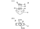
- (A) is a front view of a clip part
- (B) is a top view of a clip part.
- the band clip of this embodiment is shown
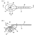
- (A) is a plan view of a state in which the clip is temporarily fixed to the clip mounting hole of the main body
- (B) is a cross-sectional view taken along line AA of (A).
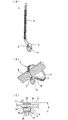
- the band wound around the wire group of the wire harness is shown through the band insertion hole
- (A) is a cross-sectional view immediately before pushing up the clip
- (B) is pushed up the clip
- the band locking claw of the shaft portion is attached to the band. It is sectional drawing inserted and locked to the locking hole.
- It is a schematic perspective view which shows the state which bound the electric wire group of the wire harness with the band clip of this embodiment. It is drawing which shows a prior art example.
- the band clip 10 of the present embodiment wraps the band 17 around the electric wire group D of the wire harness to be routed in the automobile and binds and fixes the band 17 at the position of the main body 11 and protrudes from the lower surface of the main body 11.
- the clip 19 is inserted and locked into the panel hole 31 of the vehicle body panel 30 to fix the electric wire group D of the wire harness to the vehicle body.
- the main body 11 has an L shape in which the vertical plate portion 14 is refracted from one end of the horizontal plate portion 12, and a clip mounting hole in which the columnar shaft portion 20 of the clip 19 is movably fitted in the center of the horizontal plate portion 12. 13, and an elliptical dish portion 16 surrounding the clip mounting hole 13 is provided on the lower surface side of the horizontal plate portion 12.
- the vertical plate portion 14 is provided with a band insertion hole 15 through which the band 17 wound around the electric wire group D is inserted, and a band-like band 17 wound around the electric wire group D of the wire harness from the protruding end of the vertical plate portion 14.
- the band 17 is provided with a locking hole 18 having a diameter similar to that of the clip mounting hole 13 at an interval in the length direction.
- the clip 19 is formed as a separate body from the main body 11 in which the band 17 is integrally formed, and the lower end of the shaft portion 20 of the clip 19 is movably fitted in the clip mounting hole 13 of the horizontal plate portion 12.
- the blade portion 21 inserted and locked in the panel hole 31 of the vehicle body panel 30 is provided in a folded shape.
- four band locking claws 22 are inclined at 90 ° intervals in the circumferential direction from the tip end of the shaft portion 20 to the rear side, as shown in FIGS. 1 and 2.
- main body locking claws 23 are projected on the outer peripheral surface of the intermediate portion of the shaft portion 20 at an interval of 90 degrees in the circumferential direction so as to incline from the rear to the front of the shaft portion 20. ing. That is, the band 17 wound around the electric wire group D is inserted into the band insertion hole 15 of the vertical plate portion 14 and tightened, and the predetermined locking hole 18 of the band 17 is communicated with the upper surface side of the clip mounting hole 13 of the horizontal plate portion 12.
- the band locking claw 22 at the tip of the clip shaft 20 is inserted and locked into the locking hole 18 of the band 17 in the tightened state, and the body at the intermediate position of the clip shaft 20
- the locking claw 23 is in contact with the lower surface of the main body 11.
- the clip 20 is inserted in a state where the shaft portion 20 of the clip 19 is movably inserted into the clip mounting hole 13 and the band locking claw 22 at the tip of the shaft portion 20 is bent inward.
- the clip 19 is temporarily fixed to the clip mounting hole 13 by being locked to the opening peripheral edge of the mounting hole 13 tip.
- the band 17 is wound around the outer periphery of the electric wire group D, and the band 17 is inserted into the band insertion hole 15 of the vertical plate portion 14 and tightened.
- a predetermined locking hole 18 of the band 17 arranged on the upper surface side of the clip mounting hole 13 of the horizontal plate portion 12 is in communication with the clip mounting hole 13 (FIG. 4A).
- the shaft part 20 temporarily fixed in the clip mounting hole 13 is inserted into the locking hole 18 of the band 17, and the band locking claw 22 at the tip of the shaft part is inserted into the locking hole.
- the main body locking claw 23 in the middle position of the shaft portion comes into contact with the lower surface of the main body 11 while elastically returning to the upper end edge of the shaft 18 (FIG. 4B).
- the shaft portion 20 of the clip 19 is inserted into the locking hole 18 of the tightened band 17, and the shaft portion 20 is sandwiched between the band locking claw 22 and the body locking claw 23 of the shaft portion 20.
- the band 17 is provided with a plurality of locking holes 18 at intervals in the length direction as described above, but in FIG. 4, a predetermined locking hole 18 into which the band locking claw 22 is inserted and locked is provided. Only displaying.
- the height of the main body can be kept low. Therefore, the wiring space for the wire harness can be expanded and the stability of the wire harness fixed to the vehicle body can be increased. Moreover, since the upper wall and side wall when it was set as the box-shaped main body become unnecessary, a weight and manufacturing cost can also be suppressed.
Landscapes
- Engineering & Computer Science (AREA)
- General Engineering & Computer Science (AREA)
- Mechanical Engineering (AREA)
- Architecture (AREA)
- Civil Engineering (AREA)
- Structural Engineering (AREA)
- Installation Of Indoor Wiring (AREA)
- Clamps And Clips (AREA)
- Connection Of Plates (AREA)
Abstract
Description
前記本体は、クリップ取付穴を設けた横板部の一端からバンド挿通穴を設けた縦板部を屈折させたL形状とし、前記縦板部の突出端から前記バンドを延在させ、該バンドには長さ方向に間隔をあけて係止穴を設けている一方、
前記クリップは前記本体のクリップ取付穴に移動可能に内嵌する軸部と、該軸部の一端側に設けた車体係止用の羽根部と、該軸部の他端外周面に突設したバンド係止爪と、該軸部の中間部外周面に突設した本体係止爪とを備え、
前記本体のクリップ取付穴に移動可能に前記軸部を挿入したクリップの前記バンド係止爪を前記クリップ取付穴の先端開口周縁に係止して仮止めしておき、ワイヤハーネスの電線群に巻き付けた前記バンドを前記バンド挿通穴に通した状態で前記クリップを押圧してバンド係止爪を前記バンドの係止穴に挿入係止し、該位置で前記本体係止爪を前記本体の表面に当接する構成としているバンドクリップを提供している。
また、前記のように、本体係止爪を前方に向けて傾斜させて突出することにより、バンド係止爪がバンドの係止穴に挿入係止したときに、前方にテーパ状に広がる本体係止爪がバンドと反対側の本体表面に確実に当接し、該本体係止爪がストッパーの役割を果たして軸部がこれ以上前方に移動するのを阻止することができる。
即ち、前記構成により、軸部先端のバンド係止爪をバンドの係止穴に挿入係止した後、該軸部がバンドの係止穴から抜けたり軸部前後方向にずれたりすることが効果的に防止されるため、バンドによる結束を一層強固に保持することができる。
図1乃至図5は本発明の実施形態を示している。本実施形態のバンドクリップ10は、図5に示すように、自動車に配索するワイヤハーネスの電線群Dにバンド17を巻き付けて本体11の位置で結束固定すると共に、本体11の下面から突出させたクリップ19を車体パネル30のパネル穴31に挿入係止することで、ワイヤハーネスの電線群Dを車体に固定するものであり、樹脂成形品からなるバンドクリップ10は、本体11と、該本体11から延在させて一体成形したバンド17と、本体11に移動可能に取り付けて本体11の下面から突出させる車体係止用のクリップ19から構成している。
この状態で、クリップ19を押し上げることにより、クリップ取付穴13内に仮止めされていた軸部20がバンド17の係止穴18に挿入され、軸部先端のバンド係止爪22が係止穴18の上端縁に弾性復帰して係止すると共に、軸部中間位置の本体係止爪23が本体11の下面に当接する[図4(B)]。このように、締め付け状態のバンド17の係止穴18にクリップ19の軸部20が挿入され、該軸部20のバンド係止爪22と本体係止爪23との上下の挟み込みによって軸部20がバンド17の係止穴18から抜けたり上下にずれたりすることがないため、バンド17の強固な結束が保持される。
なお、バンド17には、前記のように係止穴18を長さ方向に間隔をあけて複数設けているが、図4ではバンド係止爪22が挿入係止される所定の係止穴18のみ表示している。
11 本体
12 横板部
13 クリップ取付穴
14 縦板部
15 バンド挿通穴
16 皿部
17 バンド
18 係止穴
19 クリップ
20 軸部
21 羽根部
22 バンド係止爪
23 本体係止爪
30 車体パネル
31 パネル穴
Claims (3)
- 本体と、該本体から延在させて一体成形したバンドと、前記本体に移動可能に取り付けて該本体の外面から突出させる車体係止用のクリップとを備え、
前記本体は、クリップ取付穴を設けた横板部の一端からバンド挿通穴を設けた縦板部を屈折させたL形状とし、前記縦板部の突出端から前記バンドを延在させ、該バンドには長さ方向に間隔をあけて係止穴を設けている一方、
前記クリップは前記本体のクリップ取付穴に移動可能に内嵌する軸部と、該軸部の一端側に設けた車体係止用の羽根部と、該軸部の他端外周面に突設したバンド係止爪と、該軸部の中間部外周面に突設した本体係止爪とを備え、
前記本体のクリップ取付穴に移動可能に前記軸部を挿入したクリップの前記バンド係止爪を前記クリップ取付穴の先端開口周縁に係止して仮止めしておき、ワイヤハーネスの電線群に巻き付けた前記バンドを前記バンド挿通穴に通した状態で前記クリップを押圧してバンド係止爪を前記バンドの係止穴に挿入係止し、該位置で前記本体係止爪を前記本体の表面に当接する構成としているバンドクリップ。 - 前記本体の横板部には前記クリップ取付穴を囲む皿部を突設している請求項1に記載のバンドクリップ。
- 前記クリップの前記バンド係止爪および本体係止爪は前記軸部の外周に周方向に間隔をあけて2~4個設け、前記バンド係止爪は軸部先端から後方に向けて傾斜させて突出している一方、前記本体係止爪は前記バンド係止爪側の前方に向けて傾斜させて突出している請求項1または請求項2に記載のバンドクリップ。
Priority Applications (3)
| Application Number | Priority Date | Filing Date | Title |
|---|---|---|---|
| US13/878,792 US8899532B2 (en) | 2010-10-26 | 2011-03-28 | Band clip |
| GB1305149.5A GB2498125B (en) | 2010-10-26 | 2011-03-28 | Band clip |
| CN201180051574.6A CN103190047B (zh) | 2010-10-26 | 2011-03-28 | 束带夹紧件 |
Applications Claiming Priority (2)
| Application Number | Priority Date | Filing Date | Title |
|---|---|---|---|
| JP2010240046A JP2012095434A (ja) | 2010-10-26 | 2010-10-26 | バンドクリップ |
| JP2010-240046 | 2010-10-26 |
Publications (1)
| Publication Number | Publication Date |
|---|---|
| WO2012056747A1 true WO2012056747A1 (ja) | 2012-05-03 |
Family
ID=45993484
Family Applications (1)
| Application Number | Title | Priority Date | Filing Date |
|---|---|---|---|
| PCT/JP2011/057659 Ceased WO2012056747A1 (ja) | 2010-10-26 | 2011-03-28 | バンドクリップ |
Country Status (5)
| Country | Link |
|---|---|
| US (1) | US8899532B2 (ja) |
| JP (1) | JP2012095434A (ja) |
| CN (1) | CN103190047B (ja) |
| GB (1) | GB2498125B (ja) |
| WO (1) | WO2012056747A1 (ja) |
Cited By (1)
| Publication number | Priority date | Publication date | Assignee | Title |
|---|---|---|---|---|
| JP2017538077A (ja) * | 2014-11-25 | 2017-12-21 | ボルボトラックコーポレーション | 車両の支持構造体にワイヤーハーネスを取り付ける自己締結ブラケット、及び、これを備えた車両 |
Families Citing this family (21)
| Publication number | Priority date | Publication date | Assignee | Title |
|---|---|---|---|---|
| US9709192B1 (en) * | 2011-04-08 | 2017-07-18 | Com Dangles, Llc | Strap for suspending wires that is reconfigurable for various attachment systems |
| EP2590283A1 (en) * | 2011-11-03 | 2013-05-08 | CMP Products Limited | A Tie for Fixing an Article to a Surface |
| SE536905C2 (sv) * | 2012-08-22 | 2014-10-21 | Jan Berglund Med Inco Innovation F | Buntband för montage av kablar mot en panel |
| JP2014099989A (ja) * | 2012-11-14 | 2014-05-29 | Sumitomo Wiring Syst Ltd | ワイヤーハーネス |
| JP6114479B2 (ja) * | 2013-08-20 | 2017-04-12 | マッカイ メモリアル ホスピタル | 血流を制限するための方法および装置 |
| JP2015077013A (ja) * | 2013-10-10 | 2015-04-20 | 住友電装株式会社 | ワイヤハーネス用固定具及びワイヤハーネス用固定具が取り付けられた固定具付ワイヤハーネスの製造方法 |
| USD745225S1 (en) * | 2014-08-01 | 2015-12-08 | Denise Siria-Womach | Tamper evident safety seal |
| TWI573361B (zh) * | 2015-07-21 | 2017-03-01 | 鴻海精密工業股份有限公司 | 固定裝置 |
| FR3039599B1 (fr) * | 2015-07-31 | 2018-01-12 | A Raymond Et Cie | Joint d'etancheite du type parapluie |
| US20170063064A1 (en) | 2015-08-24 | 2017-03-02 | William Gary Gintz | Releasable holder for cables and conduit |
| US20190267785A1 (en) | 2015-08-24 | 2019-08-29 | Sticnstac, LLC | Releasable holder for cables and conduit |
| US10495126B2 (en) | 2017-02-07 | 2019-12-03 | William BEJIN | Push pin with antirotational stopper and method of use thereof |
| JP1590183S (ja) * | 2017-03-06 | 2017-11-06 | ||
| US11116192B2 (en) * | 2017-10-04 | 2021-09-14 | Gye S. Nitta | Live bait zip tie |
| JP1612261S (ja) * | 2017-10-26 | 2018-08-27 | ||
| JP6848907B2 (ja) * | 2018-03-12 | 2021-03-24 | 京セラドキュメントソリューションズ株式会社 | 固定用結束バンド |
| USD874905S1 (en) * | 2018-09-12 | 2020-02-11 | Kent Gaddy | Multipurpose strap consisting of a flexible strap and a flexible anchoring clip |
| CN113661717B (zh) * | 2019-04-04 | 2024-05-31 | 五十平方株式会社 | 耳机套及其固定件 |
| JP2022110760A (ja) * | 2021-01-19 | 2022-07-29 | 株式会社オートネットワーク技術研究所 | クランプ及びワイヤハーネス |
| USD1049838S1 (en) * | 2022-10-18 | 2024-11-05 | Avery Dennison Retail Information Services Llc | Fastener device |
| EP4455525B1 (en) * | 2023-04-28 | 2025-09-24 | Hella Autotechnik Nova, s.r.o. | Cable binder for vehicles, cable-binding assembly, and vehicle lamp with the assembly |
Citations (5)
| Publication number | Priority date | Publication date | Assignee | Title |
|---|---|---|---|---|
| JPS5783784U (ja) * | 1980-11-07 | 1982-05-24 | ||
| JPH01130585U (ja) * | 1988-02-29 | 1989-09-05 | ||
| JP2000023335A (ja) * | 1998-07-01 | 2000-01-21 | Sumitomo Wiring Syst Ltd | クリップ |
| JP2001268757A (ja) * | 2000-03-23 | 2001-09-28 | Sumitomo Wiring Syst Ltd | コルゲートチューブ用バンドクランプ |
| JP2003230218A (ja) * | 2002-01-31 | 2003-08-15 | Sumitomo Wiring Syst Ltd | ワイヤーハーネス用バンドクリップ |
Family Cites Families (40)
| Publication number | Priority date | Publication date | Assignee | Title |
|---|---|---|---|---|
| US4342438A (en) * | 1979-07-20 | 1982-08-03 | Illinois Tool Works Inc. | Flexible strap with integral attachment means |
| JPS5783784A (en) | 1980-11-11 | 1982-05-25 | Furuengu Kk | Three branching structure of high hydraulic pressure tube |
| JPS5942548Y2 (ja) * | 1981-08-27 | 1984-12-12 | 北川工業株式会社 | 電線クランプ |
| JPH0334488Y2 (ja) * | 1985-09-19 | 1991-07-22 | ||
| US4728064A (en) * | 1986-06-13 | 1988-03-01 | Panduit Corp. | Releasable cable tie |
| US4766651A (en) * | 1987-08-24 | 1988-08-30 | Yazaki Corporation | Band clamp |
| JPH051947Y2 (ja) * | 1987-09-04 | 1993-01-19 | ||
| JPH0724325B2 (ja) | 1987-11-17 | 1995-03-15 | 住友電気工業株式会社 | 補強板一体型フレキシブル配線板の製造方法 |
| US4944683A (en) * | 1989-11-13 | 1990-07-31 | A K Stamping Co., Inc. | Grounding clamp |
| JP2534800Y2 (ja) * | 1990-04-27 | 1997-05-07 | 大和化成工業 株式会社 | ベルトクランプ |
| JPH0746855Y2 (ja) * | 1990-08-29 | 1995-10-25 | 矢崎総業株式会社 | 結束具 |
| JP2593646Y2 (ja) * | 1992-10-13 | 1999-04-12 | 住友電装株式会社 | ワイヤハーネス用バンド型クランプ |
| US5632457A (en) * | 1994-12-12 | 1997-05-27 | Navistar International Transportation Corp. | Adjustable routing clamp assembly |
| ES2164836T3 (es) * | 1995-09-19 | 2002-03-01 | Daiwa Kasei Kogyo Kk | Patas de retencion de un componente. |
| US5921510A (en) * | 1996-11-21 | 1999-07-13 | Avery Dennison Corp. | Cable tie with christmas tree fastener |
| JP2000308240A (ja) * | 1999-04-16 | 2000-11-02 | Sumitomo Wiring Syst Ltd | 線材束の保持具 |
| JP2001218341A (ja) * | 2000-01-31 | 2001-08-10 | Sumitomo Wiring Syst Ltd | フラットケーブルの保持具 |
| US6655644B1 (en) * | 2001-02-21 | 2003-12-02 | Arlington Industries, Inc. | Bridle ring for electrical and communication cable |
| JP2002320317A (ja) | 2001-04-20 | 2002-10-31 | Sumitomo Wiring Syst Ltd | バンドクリップ |
| JP2003087946A (ja) * | 2001-09-06 | 2003-03-20 | Yazaki Corp | バンドクランプ |
| JP4010487B2 (ja) * | 2002-03-22 | 2007-11-21 | 竹内工業株式会社 | スナップ構造 |
| US6747209B2 (en) * | 2002-06-19 | 2004-06-08 | Sumitomo Wiring Systems, Ltd. | Clamp |
| JP2004104924A (ja) * | 2002-09-10 | 2004-04-02 | Sumitomo Wiring Syst Ltd | クランプ |
| US7186051B2 (en) * | 2003-05-09 | 2007-03-06 | Newfrey Llc | Metal/plastic insert molded sill plate fastener |
| US20050076478A1 (en) * | 2003-07-04 | 2005-04-14 | Sumitomo Wiring Systems, Ltd. | Branch wire tie band, binding structure, and method of binding a wiring harness |
| CN1973137B (zh) * | 2004-04-09 | 2011-01-12 | 艾利丹尼森公司 | 插入式紧固件以及具有插入式紧固件的线缆扎带 |
| US7229052B2 (en) * | 2004-04-20 | 2007-06-12 | Takeuchi Industrial Co., Ltd. | Fixing tool |
| JP4689986B2 (ja) * | 2004-07-21 | 2011-06-01 | 株式会社パイオラックス | バンドクランプ |
| JP4257288B2 (ja) * | 2004-12-16 | 2009-04-22 | ポップリベット・ファスナー株式会社 | 長尺部材用クランプ |
| US7762503B2 (en) * | 2005-04-20 | 2010-07-27 | Avery Dennison Corporation | Cable tie with oxygen sensor connector fastener |
| US20070023586A1 (en) * | 2005-07-28 | 2007-02-01 | Hellermann Tyton Corporation | Harness clamp tie |
| US20070272807A1 (en) * | 2006-05-18 | 2007-11-29 | Hellermanntyton Co., Ltd. | Part mounting clamp |
| US7594629B2 (en) * | 2006-06-09 | 2009-09-29 | Delphi Technologies, Inc. | Clip for fastening an article to a panel |
| US7793895B2 (en) * | 2006-06-13 | 2010-09-14 | Avery Dennison Corporation | Cable tie for an automotive valve cover |
| US7866612B2 (en) * | 2006-10-23 | 2011-01-11 | Sumitomo Wiring Systems, Ltd. | Clamp for use in wire harness |
| EP2070772A4 (en) * | 2007-01-31 | 2011-03-09 | Calsonic Kansei Corp | HARNESS ATTACH STRUCTURE |
| CN201051635Y (zh) * | 2007-05-29 | 2008-04-23 | 上海金亭汽车线束有限公司 | 带绑带的线束固定件 |
| US8230555B2 (en) * | 2008-03-19 | 2012-07-31 | GM Global Technology Operations LLC | Active material based fasteners including cable ties and twist ties |
| US7861981B2 (en) * | 2008-10-22 | 2011-01-04 | Pratt & Whitney Canada Corp. | Protective saddle mount for cable tie |
| JP5168694B2 (ja) * | 2008-12-24 | 2013-03-21 | ポップリベット・ファスナー株式会社 | クリップ |
-
2010
- 2010-10-26 JP JP2010240046A patent/JP2012095434A/ja not_active Withdrawn
-
2011
- 2011-03-28 WO PCT/JP2011/057659 patent/WO2012056747A1/ja not_active Ceased
- 2011-03-28 GB GB1305149.5A patent/GB2498125B/en not_active Expired - Fee Related
- 2011-03-28 CN CN201180051574.6A patent/CN103190047B/zh not_active Expired - Fee Related
- 2011-03-28 US US13/878,792 patent/US8899532B2/en not_active Expired - Fee Related
Patent Citations (5)
| Publication number | Priority date | Publication date | Assignee | Title |
|---|---|---|---|---|
| JPS5783784U (ja) * | 1980-11-07 | 1982-05-24 | ||
| JPH01130585U (ja) * | 1988-02-29 | 1989-09-05 | ||
| JP2000023335A (ja) * | 1998-07-01 | 2000-01-21 | Sumitomo Wiring Syst Ltd | クリップ |
| JP2001268757A (ja) * | 2000-03-23 | 2001-09-28 | Sumitomo Wiring Syst Ltd | コルゲートチューブ用バンドクランプ |
| JP2003230218A (ja) * | 2002-01-31 | 2003-08-15 | Sumitomo Wiring Syst Ltd | ワイヤーハーネス用バンドクリップ |
Cited By (2)
| Publication number | Priority date | Publication date | Assignee | Title |
|---|---|---|---|---|
| JP2017538077A (ja) * | 2014-11-25 | 2017-12-21 | ボルボトラックコーポレーション | 車両の支持構造体にワイヤーハーネスを取り付ける自己締結ブラケット、及び、これを備えた車両 |
| US10207658B2 (en) | 2014-11-25 | 2019-02-19 | Volvo Truck Corporation | Self-fastened bracket for mounting a wire harness to a support structure of a vehicle and vehicle comprising the same |
Also Published As
| Publication number | Publication date |
|---|---|
| GB2498125A (en) | 2013-07-03 |
| US8899532B2 (en) | 2014-12-02 |
| US20130193279A1 (en) | 2013-08-01 |
| JP2012095434A (ja) | 2012-05-17 |
| CN103190047B (zh) | 2016-10-12 |
| CN103190047A (zh) | 2013-07-03 |
| GB2498125B (en) | 2016-08-10 |
| GB201305149D0 (en) | 2013-05-01 |
Similar Documents
| Publication | Publication Date | Title |
|---|---|---|
| WO2012056747A1 (ja) | バンドクリップ | |
| JP4470932B2 (ja) | プロテクタ | |
| US8772636B2 (en) | Wire harness installation structure and wire harness-flattening band | |
| JP6399383B2 (ja) | 防振クランプ | |
| JP2006029566A (ja) | バンドクランプ | |
| JP7449644B2 (ja) | 配策材の結束構造 | |
| WO2014125665A1 (ja) | 結束バンド固定構造 | |
| JP2012231558A (ja) | クリップ及びクリップ付ワイヤハーネス | |
| US9343889B2 (en) | Electric wire fixing device | |
| JP5116610B2 (ja) | ワイヤハーネス平型化用バンド | |
| JP5067176B2 (ja) | 車載用の電気接続箱 | |
| WO2017199842A1 (ja) | クリップ | |
| JP2010151320A (ja) | バンドクランプ | |
| JP2018201284A (ja) | 車体固定用クリップ及びワイヤハーネス | |
| JP7235570B2 (ja) | クランプ | |
| JP2012157105A (ja) | ワイヤハーネス用のバンド | |
| JP2017141940A (ja) | アンカークリップ構造およびバンドクリップ | |
| CN105393418A (zh) | 捆扎带的安装构造 | |
| JP2012182940A (ja) | バンドクリップ | |
| JP7501411B2 (ja) | コネクタブラケット及びワイヤハーネス | |
| JP7661129B2 (ja) | ハーネス取付部材及びハーネスの固定構造 | |
| JP7294977B2 (ja) | 結束バンド | |
| JP7625991B2 (ja) | プロテクタ | |
| JP6254837B2 (ja) | 留め具 | |
| JP2005259608A (ja) | コネクタへの電線接続構造 |
Legal Events
| Date | Code | Title | Description |
|---|---|---|---|
| 121 | Ep: the epo has been informed by wipo that ep was designated in this application |
Ref document number: 11835891 Country of ref document: EP Kind code of ref document: A1 |
|
| ENP | Entry into the national phase |
Ref document number: 1305149 Country of ref document: GB Kind code of ref document: A Free format text: PCT FILING DATE = 20110328 |
|
| WWE | Wipo information: entry into national phase |
Ref document number: 1305149.5 Country of ref document: GB |
|
| WWE | Wipo information: entry into national phase |
Ref document number: 13878792 Country of ref document: US |
|
| NENP | Non-entry into the national phase |
Ref country code: DE |
|
| 122 | Ep: pct application non-entry in european phase |
Ref document number: 11835891 Country of ref document: EP Kind code of ref document: A1 |