WO2012046571A1 - ガス燃料用噴射弁 - Google Patents
ガス燃料用噴射弁 Download PDFInfo
- Publication number
- WO2012046571A1 WO2012046571A1 PCT/JP2011/071453 JP2011071453W WO2012046571A1 WO 2012046571 A1 WO2012046571 A1 WO 2012046571A1 JP 2011071453 W JP2011071453 W JP 2011071453W WO 2012046571 A1 WO2012046571 A1 WO 2012046571A1
- Authority
- WO
- WIPO (PCT)
- Prior art keywords
- valve
- annular
- annular lip
- valve plunger
- plunger
- Prior art date
- Legal status (The legal status is an assumption and is not a legal conclusion. Google has not performed a legal analysis and makes no representation as to the accuracy of the status listed.)
- Ceased
Links
Images


Classifications
-
- F—MECHANICAL ENGINEERING; LIGHTING; HEATING; WEAPONS; BLASTING
- F02—COMBUSTION ENGINES; HOT-GAS OR COMBUSTION-PRODUCT ENGINE PLANTS
- F02M—SUPPLYING COMBUSTION ENGINES IN GENERAL WITH COMBUSTIBLE MIXTURES OR CONSTITUENTS THEREOF
- F02M61/00—Fuel-injectors not provided for in groups F02M39/00 - F02M57/00 or F02M67/00
- F02M61/04—Fuel-injectors not provided for in groups F02M39/00 - F02M57/00 or F02M67/00 having valves, e.g. having a plurality of valves in series
-
- F—MECHANICAL ENGINEERING; LIGHTING; HEATING; WEAPONS; BLASTING
- F02—COMBUSTION ENGINES; HOT-GAS OR COMBUSTION-PRODUCT ENGINE PLANTS
- F02M—SUPPLYING COMBUSTION ENGINES IN GENERAL WITH COMBUSTIBLE MIXTURES OR CONSTITUENTS THEREOF
- F02M21/00—Apparatus for supplying engines with non-liquid fuels, e.g. gaseous fuels stored in liquid form
- F02M21/02—Apparatus for supplying engines with non-liquid fuels, e.g. gaseous fuels stored in liquid form for gaseous fuels
- F02M21/0218—Details on the gaseous fuel supply system, e.g. tanks, valves, pipes, pumps, rails, injectors or mixers
- F02M21/0248—Injectors
- F02M21/0251—Details of actuators therefor
- F02M21/0254—Electric actuators, e.g. solenoid or piezoelectric
-
- F—MECHANICAL ENGINEERING; LIGHTING; HEATING; WEAPONS; BLASTING
- F02—COMBUSTION ENGINES; HOT-GAS OR COMBUSTION-PRODUCT ENGINE PLANTS
- F02M—SUPPLYING COMBUSTION ENGINES IN GENERAL WITH COMBUSTIBLE MIXTURES OR CONSTITUENTS THEREOF
- F02M21/00—Apparatus for supplying engines with non-liquid fuels, e.g. gaseous fuels stored in liquid form
- F02M21/02—Apparatus for supplying engines with non-liquid fuels, e.g. gaseous fuels stored in liquid form for gaseous fuels
- F02M21/0218—Details on the gaseous fuel supply system, e.g. tanks, valves, pipes, pumps, rails, injectors or mixers
- F02M21/0248—Injectors
- F02M21/0257—Details of the valve closing elements, e.g. valve seats, stems or arrangement of flow passages
- F02M21/026—Lift valves, i.e. stem operated valves
- F02M21/0263—Inwardly opening single or multi nozzle valves, e.g. needle valves
- F02M21/0266—Hollow stem valves; Piston valves; Stems having a spherical tip
-
- F—MECHANICAL ENGINEERING; LIGHTING; HEATING; WEAPONS; BLASTING
- F02—COMBUSTION ENGINES; HOT-GAS OR COMBUSTION-PRODUCT ENGINE PLANTS
- F02M—SUPPLYING COMBUSTION ENGINES IN GENERAL WITH COMBUSTIBLE MIXTURES OR CONSTITUENTS THEREOF
- F02M21/00—Apparatus for supplying engines with non-liquid fuels, e.g. gaseous fuels stored in liquid form
- F02M21/02—Apparatus for supplying engines with non-liquid fuels, e.g. gaseous fuels stored in liquid form for gaseous fuels
- F02M21/0218—Details on the gaseous fuel supply system, e.g. tanks, valves, pipes, pumps, rails, injectors or mixers
- F02M21/0248—Injectors
- F02M21/0275—Injectors for in-cylinder direct injection, e.g. injector combined with spark plug
-
- F—MECHANICAL ENGINEERING; LIGHTING; HEATING; WEAPONS; BLASTING
- F02—COMBUSTION ENGINES; HOT-GAS OR COMBUSTION-PRODUCT ENGINE PLANTS
- F02M—SUPPLYING COMBUSTION ENGINES IN GENERAL WITH COMBUSTIBLE MIXTURES OR CONSTITUENTS THEREOF
- F02M21/00—Apparatus for supplying engines with non-liquid fuels, e.g. gaseous fuels stored in liquid form
- F02M21/02—Apparatus for supplying engines with non-liquid fuels, e.g. gaseous fuels stored in liquid form for gaseous fuels
- F02M21/0203—Apparatus for supplying engines with non-liquid fuels, e.g. gaseous fuels stored in liquid form for gaseous fuels characterised by the type of gaseous fuel
- F02M21/0209—Hydrocarbon fuels, e.g. methane or acetylene
- F02M21/0212—Hydrocarbon fuels, e.g. methane or acetylene comprising at least 3 C-Atoms, e.g. liquefied petroleum gas [LPG], propane or butane
-
- F—MECHANICAL ENGINEERING; LIGHTING; HEATING; WEAPONS; BLASTING
- F02—COMBUSTION ENGINES; HOT-GAS OR COMBUSTION-PRODUCT ENGINE PLANTS
- F02M—SUPPLYING COMBUSTION ENGINES IN GENERAL WITH COMBUSTIBLE MIXTURES OR CONSTITUENTS THEREOF
- F02M21/00—Apparatus for supplying engines with non-liquid fuels, e.g. gaseous fuels stored in liquid form
- F02M21/02—Apparatus for supplying engines with non-liquid fuels, e.g. gaseous fuels stored in liquid form for gaseous fuels
- F02M21/0203—Apparatus for supplying engines with non-liquid fuels, e.g. gaseous fuels stored in liquid form for gaseous fuels characterised by the type of gaseous fuel
- F02M21/0215—Mixtures of gaseous fuels; Natural gas; Biogas; Mine gas; Landfill gas
-
- Y—GENERAL TAGGING OF NEW TECHNOLOGICAL DEVELOPMENTS; GENERAL TAGGING OF CROSS-SECTIONAL TECHNOLOGIES SPANNING OVER SEVERAL SECTIONS OF THE IPC; TECHNICAL SUBJECTS COVERED BY FORMER USPC CROSS-REFERENCE ART COLLECTIONS [XRACs] AND DIGESTS
- Y02—TECHNOLOGIES OR APPLICATIONS FOR MITIGATION OR ADAPTATION AGAINST CLIMATE CHANGE
- Y02T—CLIMATE CHANGE MITIGATION TECHNOLOGIES RELATED TO TRANSPORTATION
- Y02T10/00—Road transport of goods or passengers
- Y02T10/10—Internal combustion engine [ICE] based vehicles
- Y02T10/30—Use of alternative fuels, e.g. biofuels
Definitions
- the present invention relates to a gas fuel injection valve that supplies natural gas such as CNG and LPG to an internal combustion engine as fuel, and in particular, a nozzle member having a valve seat and a nozzle hole penetrating through the central portion of the valve seat, and the nozzle member
- a cylindrical valve housing made of a magnetic material, connected to the rear end of the valve body, and a valve body having a fixed core disposed behind the valve body, and sliding on a sliding guide surface on the inner periphery of the valve housing
- a valve plunger which is freely fitted and seated on the valve seat and closes the nozzle hole and joined to the front end; and a valve plunger which is contracted between the fixed core and the valve plunger and is connected to the valve plunger.
- a return spring that is urged toward the seat side, and a coil that is disposed so as to surround the fixed core, and that causes the valve plunger to be attracted to the fixed core by a generated magnetic force when energized to separate from the valve seat.
- Such a gas fuel injection valve has a larger fuel injection flow rate than a liquid fuel injection valve, and therefore has a large valve plunger operating stroke and therefore a large valve closing impact. Therefore, in the conventional fuel injection valve for gas fuel, an annular lip having a semicircular cross section seated on the valve seat is formed on the rubber seating member joined to the flat front end surface of the valve plunger. As a result, the valve plunger can be closed and its impact can be reduced.
- the present invention has been made in view of such circumstances, and the height of the annular lip of the seating member is made as low as possible so that the bounce of the valve plunger, the initial plastic deformation (sagging) of the annular lip, and the valve of the annular lip To provide an injection valve for gas fuel in which an annular lip can effectively exert a mitigating function against a closing impact of a valve plunger while preventing sticking to a seat and stabilizing a fuel injection amount characteristic. With the goal.
- the present invention provides a cylindrical member made of a magnetic material, which is connected to a rear end of a nozzle member having a valve seat and a nozzle hole penetrating through the central portion of the valve seat.
- a valve body having a fixed core disposed behind the valve housing, and a sliding guide surface on the inner periphery of the valve housing.
- a valve plunger having a rubber seating member closed to the front end, a return spring that is compressed between the fixed core and the valve plunger and biases the valve plunger toward the valve seat, and surrounds the fixed core
- the front end surface of the valve plunger is disposed on the front end surface of the valve plunger.
- a circular recess that is surrounded by an annular land portion that is an outer peripheral portion of the circular recess, and an inner peripheral surface of the circular recess is formed in a taper shape that increases in diameter from the bottom surface of the circular recess toward the annular land portion.
- the annular member is joined to the seat member from the inner peripheral surface to the annular land portion to form an annular lip that is seated on the valve seat, and the annular lip of the annular lip is in the axial direction of the valve plunger.
- the first feature is that the projector is disposed on the projection surface so as to be positioned on the inner peripheral surface.
- the present invention has a second feature that the seating member is formed with a flat portion integrally connected to the inner peripheral end of the annular lip and joined to the bottom surface. .
- the annular lip of the seating member when the valve plunger is in the closed state, the annular lip of the seating member is compressed by the reaction force from the valve seat. Since it is positioned on the taper inner peripheral surface of the circular recess of the valve plunger on the axial projection surface of the plunger, the annular lip is not only compressed in the axial direction but also contracted along the taper inner peripheral surface. The annular lip is also compressed and deformed in the above two directions under a radial compressive load. Therefore, even if the height of the annular lip from the annular land portion of the valve plunger is set sufficiently low, the valve closing impact of the valve plunger can be effectively mitigated by the above-described two-way compression deformation of the annular lip. it can.
- the deformation is transmitted to the flat portion joined to the bottom surface of the circular recess of the valve plunger. Resists the compressive deformation of the annular lip in the direction of diameter reduction, so that excessive compressive deformation of the annular lip in the direction of diameter reduction can be prevented.
- FIG. 1 is a longitudinal sectional view of a gas fuel injection valve according to the present invention.
- FIG. 2 is an enlarged view of the periphery of the valve plunger of FIG.
- FIG. 3 is an enlarged view of the periphery of the seating member of FIG.
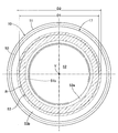
- First embodiment 4 is a view taken in the direction of arrow 4 in FIG. (First embodiment)
- a gas fuel injection valve I according to the present invention is provided with a front end portion in a mounting hole Ea provided in a pipe wall of an intake pipe E of an engine, and gas fuel is supplied during an intake stroke of the engine. The fuel is injected into the intake pipe E.
- the valve body 1 of the injection valve I is a hollow body made of a magnetic material in which a front end portion is coupled and welded to an outer peripheral surface of a cylindrical nozzle member 2 and a flange portion 2a at the rear end of the nozzle member 2.
- a cylindrical valve housing 3, a hollow cylindrical fixed core 5 integrally connected to a rear end of the valve housing 3 via a nonmagnetic cylindrical body 4, and a rear end of the fixed core 5 are integrally formed.
- a hollow cylindrical fuel inlet tube 6 is provided.
- the fixed core 5 is formed so that the inner diameter thereof is smaller than the inner diameter of the valve housing 3, and the suction surface 5 b at the front end is opposed to a later-described valve plunger 10 of the valve housing 3.
- the nozzle member 2 has a flat valve seat 7 facing the inside of the valve housing 3 and a nozzle hole 8 that penetrates the center portion and opens at the front end surface of the nozzle member 2.
- An annular shim 9 to be adjusted is interposed between the nozzle member 2 and the valve housing 3.
- valve housing 3 The inner peripheral surface of the valve housing 3 is a sliding guide surface 3a, and a valve plunger 10 made of a magnetic material is slidably fitted on the sliding guide surface 3a.
- the valve plunger 10 has a short shaft portion 11 from the front end side, a first journal portion 13 having a larger diameter than the short shaft portion 11 and slidably fitted to the sliding guide surface 3a, and a smaller diameter than the short shaft portion 11.
- the longer long shaft portion 12 and the second journal portion 14 having a diameter larger than that of the short shaft portion 11 and slidably fitted to the sliding guide surface 3a are sequentially and integrally connected.
- a rubber seating member 17 that can be seated on the valve seat 7 is joined to the front end surface of the short shaft portion 11 by baking as follows.
- a circular concave portion 51 surrounded by an annular land portion 50 serving as an outer peripheral portion is formed on the front end surface of the short shaft portion 11, that is, the front end surface of the valve plunger 10.
- the circular recess 51 is defined by a flat bottom surface 51 a orthogonal to the axis gland Y of the valve plunger 10 and a tapered inner peripheral surface 51 b that expands from the bottom surface 51 a toward the annular land portion 50.
- the seating member 17 is joined from the annular land portion 50 to the bottom surface 51a.
- the seating member 17 is joined to the bottom surface 51a, is connected to the annular land portion 50 from the inner peripheral surface 51b, and is integrally connected to the outer periphery of the flat portion 52 having a constant thickness and a circular shape.
- the annular lip 53 is formed from the annular top portion toward the flat portion 52, the inner peripheral side inclined surface 53a descending substantially parallel to the inner peripheral surface 51b, and the top portion from the annular land. It has an outer peripheral slope 53b that goes down toward the portion 50 and is formed in a substantially triangular cross section. Moreover, the annular lip 53 is formed so that the annular ridge line R at the top thereof is located on the tapered inner peripheral surface 51b on the axial projection surface of the valve plunger 10.
- the diameter D1 of the annular ridgeline R is smaller than the large diameter side diameter D2 of the tapered inner peripheral surface 51b.
- the height H of the annular lip 53 from the annular land portion 50 is set to approximately one half of the height of the annular lip of the conventional seating member. Specifically, if the height of the annular lip of the conventional seating member is 0.8 mm, the height H of the annular lip 53 of the present invention from the annular land portion 50 is set to 0.4 mm.
- the height H of the annular lip 53 is set substantially equal to the thickness T of the flat portion 52 of the seating member 17. Further, it is desirable that the angle ⁇ of the inner peripheral slope 53a with respect to the axis Y of the valve plunger 10 is set to approximately 65 °.
- a rubber-made annular cushion member 18 facing the suction surface 5b of the fixed core 5 is joined to the rear end surface of the second journal portion 14, that is, the rear end surface of the valve plunger 10, by baking.
- the A predetermined gap corresponding to the valve opening stroke of the valve plunger 10 is set between the opposing surfaces of the cushion member 18 and the fixed core 5 when the seat member 17 is seated on the valve seat 7.
- the second journal portion 14 is formed such that its axial width is larger than the axial width of the first journal portion 13, and the outer peripheral surface of the second journal portion 14 is on the fixed core 5 side on the valve housing 3 side.
- a first sliding surface 14a slidably fitted to the sliding guide surface 3a
- a second sliding surface 14b slidably fitted to the sliding guide surface 3a on the long shaft portion 12 side
- An annular groove 14c that separates the first and second sliding surfaces 14a and 14b is formed.
- the annular groove 14 c is formed so that the groove bottom diameter is sufficiently larger than the outer diameter of the long shaft portion 12.
- the outer peripheral surface of the valve plunger 10 is coated with a fluororesin film 19.
- a coil assembly 20 is disposed from the region of the valve housing 3 where the second journal portion 14 is fitted to the fixed core 5 and surrounding them.
- the coil assembly 20 includes a valve housing 3, a bobbin 21 fitted to the outer periphery of the nonmagnetic cylindrical body 4 and the fixed core 5, and a coil 22 wound around the outer periphery of the bobbin 21.
- a magnetic coil housing 23 is disposed on the outer periphery of the solid 20 to cover it.
- the front end of the coil housing 23 has an end wall 23a that receives the front end surface of the coil assembly 20 and fits to the outer periphery of the valve housing 3, and a front yoke that contacts the front surface of the end wall 23a.
- a rear yoke flange 25 that is fitted integrally with the inner peripheral surface of the rear end of the coil housing 23 while the flange 24 projects integrally with the outer peripheral surface of the valve housing 3 and abuts the rear end surface of the coil assembly 20 is the fixed core 5.
- the coil assembly 20 and the coil housing 23 are attached to the valve body 1.
- a resin mold layer 26 that continuously covers the outer peripheral surfaces of the front yoke flange 24, the coil housing 23, and the fuel inlet cylinder 6 is formed. The resin mold layer 26 projects to one side of the resin mold layer 26, and the coil A coupler 28 that holds a current-carrying terminal 27 that is connected to 22 is integrally formed.
- the valve plunger 10 includes a large-diameter vertical hole 30 starting from the rear end surface and ending before the front end surface of the first journal portion 13, and a small diameter starting from the bottom surface of the large-diameter vertical hole 30 and ending before the front end surface of the short shaft portion 11.
- a vertical hole 31 and a plurality of horizontal holes 32, 32... That open the small-diameter vertical hole 31 to the outer peripheral surface of the short shaft portion 11 are provided.
- a plurality of reinforcing ribs 12 a, 12 a... Extending in the axial direction are formed on the outer peripheral surface of the long shaft portion 12.
- the large-diameter vertical hole 30 communicates with the hollow portion 5 a of the fixed core 5, and the rearward annular step formed between the large-diameter vertical hole 30 and the small-diameter vertical hole 31 is a spring seat 34.
- the spring seat 34 is disposed in front of the first sliding surface 14a.
- a hollow retainer 37 made of a spring pin that supports a return spring 35 that urges the valve plunger 10 toward the valve seat 7 with the spring seat 34.
- a fuel filter 38 is attached to the inlet of the hollow portion 6a of the fuel inlet cylinder 6 connected to the hollow portion 5a of the fixed core 5.
- a pair of front and rear synthetic resin ring members 41 and 42 defining an annular front seal groove 40 are fitted on the outer periphery of the nozzle member 2, and the nozzle member 2 is sucked into the engine intake air into the front seal groove 40.
- a front O-ring 43 that is in close contact with the inner peripheral surface thereof is attached.
- An annular rear seal groove 45 is defined on the outer periphery of the rear end portion of the fuel inlet tube 6 by a flange 46 formed at the rear end of the fuel inlet tube 6 and the rear end surface of the resin mold layer 26.
- a rear O-ring 47 that is in close contact with the inner peripheral surface is attached to the seal groove 45.
- the valve plunger 10 In the demagnetized state of the coil 22, the valve plunger 10 is pressed forward by the urging force of the return spring 35, and the seat member 17 is seated on the valve seat 7.
- the gas fuel sent from the gas fuel tank (not shown) to the fuel distribution pipe D flows into the fuel inlet cylinder 6 and is filtered by the fuel filter 38, and the large diameter vertical axis of the hollow retainer 37 and the valve plunger 10 is obtained. It waits in the valve housing 3 through the hole 30, the small diameter vertical hole 31, and the horizontal holes 32, 32.
- the annular lip 53 of the seating member 17 is compressed by the reaction force from the valve seat 7.
- the annular lip 53 has a substantially triangular cross section, and the annular ridge line R at the top of the annular lip 53 is projected in the axial direction of the valve plunger 10. Since it is positioned on the tapered inner peripheral surface 51b of the circular recess 51 of the valve plunger 10 on the surface, the annular lip 53 is not only along the axial compression load a but also along the tapered inner peripheral surface 51b.
- the annular lip 53 is also compressed and deformed in the above two directions by receiving the compressive load b in the diameter reducing direction. Therefore, although the height H of the annular lip 53 from the annular land portion 50 of the valve plunger 10 is set to be approximately one half of the height of the conventional annular lip, the two directions of the annular lip 53 are set. Thus, the valve closing impact of the valve plunger 10 can be effectively mitigated. Further, since the height H of the annular lip 53 can be set sufficiently low in this way, the bounce of the valve plunger 10, the initial plastic deformation (sagging) of the annular lip 53, the valve seat of the annular lip 53, and so on. 7 can be prevented, and the fuel injection amount characteristic can be stabilized.
- the annular lip 53 when the annular lip 53 is compressed and deformed in the diameter reducing direction b, the deformation is transmitted to the flat portion 52 joined to the bottom surface 51a of the circular recess 51 of the valve plunger 10, and the flat portion 52 is annular. Since the lip 53 resists compression deformation in the diameter reduction direction b, excessive compression deformation in the diameter reduction direction b of the annular lip 53 can be prevented.
- the magnetic flux generated by the coil 22 sequentially travels in the coil housing 23, the valve housing 3, the second journal portion 14, the fixed core 5, the rear yoke flange 25, and the coil housing 23.
- the opening limit of the seating member 17 relative to the valve seat 7 is attracted by the fixed core 5 against the set load of the return spring 35 and the rubber cushion member 18 of the valve plunger 10 abuts against the front end surface of the fixed core 5. Is regulated.
- the second journal portion 14 is formed such that its axial width is larger than the axial width of the first journal portion 13, and the outer peripheral surface of the second journal portion 14 has a fixed core.
- a first sliding surface 14a slidably fitted to the sliding guide surface 3a of the valve housing 3 on the 5th side and a second slidably fitted to the sliding guide surface 3a on the long shaft portion 12 side.
- the first and second sliding surfaces of the second journal portion 14 separated by the annular groove 14c. 14a and 14b have a relatively narrow axial width similar to that of the first journal portion 13, so that the oil mixed in the gas fuel introduced into the valve housing 3 is in contact with the first journal portion 13 and the first journal portion 13. Even if an oil film is formed by entering between the first and second sliding surfaces 14a, 14b and the sliding guide surface 3a, the oil film is easily sheared by the valve opening force due to the magnetic force of the valve plunger 10. Therefore, sticking of the valve plunger 10 to the sliding guide surface 3a is eliminated. Furthermore, the fluororesin film 19 coated on the outer peripheral surface of the valve plunger 10 promotes shearing of the oil film.
- the second journal section 14 can satisfy the conflicting requirements of securing the necessary magnetic path area and preventing sticking by the oil film, and can improve the valve opening response of the valve plunger 10.
Landscapes
- Engineering & Computer Science (AREA)
- Chemical & Material Sciences (AREA)
- Combustion & Propulsion (AREA)
- Mechanical Engineering (AREA)
- General Engineering & Computer Science (AREA)
- Chemical Kinetics & Catalysis (AREA)
- General Chemical & Material Sciences (AREA)
- Oil, Petroleum & Natural Gas (AREA)
- Analytical Chemistry (AREA)
- Fuel-Injection Apparatus (AREA)
- Magnetically Actuated Valves (AREA)
Priority Applications (3)
| Application Number | Priority Date | Filing Date | Title |
|---|---|---|---|
| CN201180048520.4A CN103154490B (zh) | 2010-10-08 | 2011-09-21 | 气体燃料用喷射阀 |
| US13/823,124 US9027859B2 (en) | 2010-10-08 | 2011-09-21 | Gas fuel injection valve |
| EP11830504.4A EP2626542B1 (en) | 2010-10-08 | 2011-09-21 | Gas fuel injection valve |
Applications Claiming Priority (2)
| Application Number | Priority Date | Filing Date | Title |
|---|---|---|---|
| JP2010228268A JP5618751B2 (ja) | 2010-10-08 | 2010-10-08 | ガス燃料用噴射弁 |
| JP2010-228268 | 2010-10-08 |
Publications (1)
| Publication Number | Publication Date |
|---|---|
| WO2012046571A1 true WO2012046571A1 (ja) | 2012-04-12 |
Family
ID=45927566
Family Applications (1)
| Application Number | Title | Priority Date | Filing Date |
|---|---|---|---|
| PCT/JP2011/071453 Ceased WO2012046571A1 (ja) | 2010-10-08 | 2011-09-21 | ガス燃料用噴射弁 |
Country Status (5)
| Country | Link |
|---|---|
| US (1) | US9027859B2 (https=) |
| EP (1) | EP2626542B1 (https=) |
| JP (1) | JP5618751B2 (https=) |
| CN (1) | CN103154490B (https=) |
| WO (1) | WO2012046571A1 (https=) |
Cited By (2)
| Publication number | Priority date | Publication date | Assignee | Title |
|---|---|---|---|---|
| WO2014050506A1 (ja) * | 2012-09-28 | 2014-04-03 | 株式会社ケーヒン | 燃料噴射弁 |
| US20150152828A1 (en) * | 2013-11-29 | 2015-06-04 | Aisan Kogyo Kabushiki Kaisha | Fuel injector |
Families Citing this family (11)
| Publication number | Priority date | Publication date | Assignee | Title |
|---|---|---|---|---|
| JP5482836B2 (ja) * | 2011-09-20 | 2014-05-07 | 株式会社デンソー | 燃料噴射弁及び燃料噴射弁の製造方法 |
| JP6061074B2 (ja) * | 2012-09-28 | 2017-01-18 | 株式会社ケーヒン | 燃料噴射弁 |
| DE102014212339A1 (de) * | 2014-06-26 | 2015-12-31 | Robert Bosch Gmbh | Injektor, insbesondere Einblasinjektor für gasförmige Kraftstoffe |
| CN110651116B (zh) * | 2017-05-23 | 2021-12-24 | 三菱电机株式会社 | 喷射器 |
| US10167817B1 (en) * | 2017-11-24 | 2019-01-01 | Dongbangtech Co., Ltd. | Compressed natural gas injector |
| CN108547710B (zh) * | 2018-02-13 | 2020-09-29 | 上海柯来浦能源科技有限公司 | 一种直喷气体喷嘴及其发动机和动力系统 |
| CN111288841B (zh) * | 2019-12-31 | 2022-01-07 | 南京理工大学 | 导气式自动机多功能气动装置 |
| WO2023233661A1 (ja) * | 2022-06-03 | 2023-12-07 | 日立Astemo株式会社 | 気体燃料噴射弁 |
| CN115234407B (zh) * | 2022-07-22 | 2024-04-09 | 一汽解放汽车有限公司 | 截止阀及气体喷射器 |
| CN115355114B (zh) * | 2022-09-06 | 2023-10-20 | 一汽解放汽车有限公司 | 气体喷射器和汽车 |
| US12385452B2 (en) * | 2023-04-17 | 2025-08-12 | Cummins Inc. | Fuel injector for gaseous fuel and valve assembly for the same |
Citations (3)
| Publication number | Priority date | Publication date | Assignee | Title |
|---|---|---|---|---|
| JP2006077777A (ja) * | 2005-12-07 | 2006-03-23 | Aisan Ind Co Ltd | 燃料噴射弁 |
| JP2007040245A (ja) | 2005-08-04 | 2007-02-15 | Keihin Corp | ガス燃料用噴射弁 |
| JP2007507645A (ja) * | 2003-10-07 | 2007-03-29 | メッド ソチエタ ペル アチオーニ | ガス状燃料用電動噴射器 |
Family Cites Families (11)
| Publication number | Priority date | Publication date | Assignee | Title |
|---|---|---|---|---|
| DE19529375A1 (de) | 1995-08-10 | 1997-02-13 | Bosch Gmbh Robert | Brennstoffeinspritzventil |
| JP2000087826A (ja) | 1998-09-14 | 2000-03-28 | Toyota Motor Corp | 燃料噴射弁およびその製造方法 |
| US6655611B2 (en) | 2001-02-12 | 2003-12-02 | Delphi Technologies, Inc. | Electromagnetic fuel injector comprising flexible element for positioning armature |
| JP2004068671A (ja) * | 2002-08-05 | 2004-03-04 | Keihin Corp | ガス燃料噴射弁 |
| DE10258859A1 (de) * | 2002-12-17 | 2004-07-08 | Robert Bosch Gmbh | Fluidventil |
| DE10351207A1 (de) * | 2003-11-03 | 2005-06-02 | Robert Bosch Gmbh | Ventil zum Steuern eines Fluids |
| JP2006188976A (ja) * | 2005-01-05 | 2006-07-20 | Tomoki Yamazaki | 水素ガスエンジンと水素ガスエンジンに使用するインジェクター |
| JP4529835B2 (ja) | 2005-08-03 | 2010-08-25 | トヨタ自動車株式会社 | 内燃機関の制御装置 |
| CN2937519Y (zh) | 2006-08-02 | 2007-08-22 | 北京爱尼机电有限公司 | 压缩天然气喷射器 |
| JP2010038109A (ja) * | 2008-08-07 | 2010-02-18 | Keihin Corp | ガス燃料用噴射弁 |
| US8899500B2 (en) | 2009-03-30 | 2014-12-02 | Keihin Corporation | Gas fuel injection valve |
-
2010
- 2010-10-08 JP JP2010228268A patent/JP5618751B2/ja active Active
-
2011
- 2011-09-21 US US13/823,124 patent/US9027859B2/en active Active
- 2011-09-21 WO PCT/JP2011/071453 patent/WO2012046571A1/ja not_active Ceased
- 2011-09-21 EP EP11830504.4A patent/EP2626542B1/en active Active
- 2011-09-21 CN CN201180048520.4A patent/CN103154490B/zh active Active
Patent Citations (3)
| Publication number | Priority date | Publication date | Assignee | Title |
|---|---|---|---|---|
| JP2007507645A (ja) * | 2003-10-07 | 2007-03-29 | メッド ソチエタ ペル アチオーニ | ガス状燃料用電動噴射器 |
| JP2007040245A (ja) | 2005-08-04 | 2007-02-15 | Keihin Corp | ガス燃料用噴射弁 |
| JP2006077777A (ja) * | 2005-12-07 | 2006-03-23 | Aisan Ind Co Ltd | 燃料噴射弁 |
Cited By (4)
| Publication number | Priority date | Publication date | Assignee | Title |
|---|---|---|---|---|
| WO2014050506A1 (ja) * | 2012-09-28 | 2014-04-03 | 株式会社ケーヒン | 燃料噴射弁 |
| JP2014070575A (ja) * | 2012-09-28 | 2014-04-21 | Keihin Corp | 燃料噴射弁 |
| US20150152828A1 (en) * | 2013-11-29 | 2015-06-04 | Aisan Kogyo Kabushiki Kaisha | Fuel injector |
| US9441589B2 (en) * | 2013-11-29 | 2016-09-13 | Aisan Kogyo Kabushiki Kaisha | Fuel injector |
Also Published As
| Publication number | Publication date |
|---|---|
| JP2012082726A (ja) | 2012-04-26 |
| EP2626542A4 (en) | 2016-12-28 |
| US9027859B2 (en) | 2015-05-12 |
| US20130299610A1 (en) | 2013-11-14 |
| CN103154490A (zh) | 2013-06-12 |
| JP5618751B2 (ja) | 2014-11-05 |
| CN103154490B (zh) | 2015-06-17 |
| EP2626542B1 (en) | 2018-09-26 |
| EP2626542A1 (en) | 2013-08-14 |
Similar Documents
| Publication | Publication Date | Title |
|---|---|---|
| JP5618751B2 (ja) | ガス燃料用噴射弁 | |
| JP2012082726A5 (https=) | ||
| US10718296B2 (en) | High-pressure fuel supply pump including an electromagnetically driven intake valve | |
| US6223727B1 (en) | Seal member mounting structure in electromagnetic fuel injection valve | |
| US9080539B2 (en) | Electromagnetic fuel injection valve | |
| CN102365447A (zh) | 气体燃料用喷射阀 | |
| US20140374512A1 (en) | Electromagnetic fuel injection valve | |
| JP2010038110A (ja) | ガス燃料用噴射弁 | |
| JP5639426B2 (ja) | ガス燃料用噴射弁 | |
| JP5266124B2 (ja) | ガス燃料用噴射弁 | |
| JP5924771B2 (ja) | 燃料噴射弁 | |
| WO2011013435A1 (ja) | 電磁式燃料噴射弁 | |
| US7341204B2 (en) | Fuel injection valve | |
| JP5661397B2 (ja) | ガス燃料用噴射弁及びその製造方法 | |
| JP2010038109A (ja) | ガス燃料用噴射弁 | |
| JP2014062524A (ja) | 燃料噴射弁 | |
| JP6412379B2 (ja) | 燃料噴射弁 | |
| JP2014055569A (ja) | ガス燃料用噴射弁 | |
| US7464884B2 (en) | Fuel injection valve | |
| JP2022146785A (ja) | ガス燃料用噴射弁 | |
| JP3930012B2 (ja) | 燃料噴射弁 | |
| JP2014020201A (ja) | 電磁式燃料噴射弁 | |
| WO2019207753A1 (ja) | 燃料噴射弁 | |
| JP2006070814A (ja) | 燃料噴射ノズル |
Legal Events
| Date | Code | Title | Description |
|---|---|---|---|
| WWE | Wipo information: entry into national phase |
Ref document number: 201180048520.4 Country of ref document: CN |
|
| 121 | Ep: the epo has been informed by wipo that ep was designated in this application |
Ref document number: 11830504 Country of ref document: EP Kind code of ref document: A1 |
|
| DPE1 | Request for preliminary examination filed after expiration of 19th month from priority date (pct application filed from 20040101) | ||
| NENP | Non-entry into the national phase |
Ref country code: DE |
|
| WWE | Wipo information: entry into national phase |
Ref document number: 2011830504 Country of ref document: EP |
|
| WWE | Wipo information: entry into national phase |
Ref document number: 13823124 Country of ref document: US |