WO2012032683A1 - Dispositif sans fil - Google Patents
Dispositif sans fil Download PDFInfo
- Publication number
- WO2012032683A1 WO2012032683A1 PCT/JP2011/001388 JP2011001388W WO2012032683A1 WO 2012032683 A1 WO2012032683 A1 WO 2012032683A1 JP 2011001388 W JP2011001388 W JP 2011001388W WO 2012032683 A1 WO2012032683 A1 WO 2012032683A1
- Authority
- WO
- WIPO (PCT)
- Prior art keywords
- level
- terminal
- terminals
- concentrator
- unit
- Prior art date
Links
Images


Classifications
-
- H—ELECTRICITY
- H04—ELECTRIC COMMUNICATION TECHNIQUE
- H04W—WIRELESS COMMUNICATION NETWORKS
- H04W40/00—Communication routing or communication path finding
- H04W40/02—Communication route or path selection, e.g. power-based or shortest path routing
- H04W40/12—Communication route or path selection, e.g. power-based or shortest path routing based on transmission quality or channel quality
-
- H—ELECTRICITY
- H04—ELECTRIC COMMUNICATION TECHNIQUE
- H04W—WIRELESS COMMUNICATION NETWORKS
- H04W40/00—Communication routing or communication path finding
- H04W40/02—Communication route or path selection, e.g. power-based or shortest path routing
- H04W40/04—Communication route or path selection, e.g. power-based or shortest path routing based on wireless node resources
- H04W40/08—Communication route or path selection, e.g. power-based or shortest path routing based on wireless node resources based on transmission power
-
- H—ELECTRICITY
- H04—ELECTRIC COMMUNICATION TECHNIQUE
- H04W—WIRELESS COMMUNICATION NETWORKS
- H04W48/00—Access restriction; Network selection; Access point selection
- H04W48/20—Selecting an access point
-
- Y—GENERAL TAGGING OF NEW TECHNOLOGICAL DEVELOPMENTS; GENERAL TAGGING OF CROSS-SECTIONAL TECHNOLOGIES SPANNING OVER SEVERAL SECTIONS OF THE IPC; TECHNICAL SUBJECTS COVERED BY FORMER USPC CROSS-REFERENCE ART COLLECTIONS [XRACs] AND DIGESTS
- Y02—TECHNOLOGIES OR APPLICATIONS FOR MITIGATION OR ADAPTATION AGAINST CLIMATE CHANGE
- Y02D—CLIMATE CHANGE MITIGATION TECHNOLOGIES IN INFORMATION AND COMMUNICATION TECHNOLOGIES [ICT], I.E. INFORMATION AND COMMUNICATION TECHNOLOGIES AIMING AT THE REDUCTION OF THEIR OWN ENERGY USE
- Y02D30/00—Reducing energy consumption in communication networks
- Y02D30/70—Reducing energy consumption in communication networks in wireless communication networks
Definitions
- the present invention relates to a method for searching for a communication route when a wireless device performs wireless communication.
- a communication route is collectively managed by a server located at the top of the system (see, for example, Patent Document 1). Further, a route having a large difference is searched by looking at a difference in electric field strength between a terminal that communicates and an adjacent terminal, and a communication route is constructed (see, for example, Patent Document 2).
- JP 2007-335994 A Japanese Patent Laid-Open No. 11-168526
- the route cannot be determined unless all the wireless terminals constituting the system are installed, and the field strength discriminating means having a wide dynamic range capable of discriminating the difference in the field strength between the terminals. It was necessary. For this reason, there has been a problem that the system is not workable, for example, the communication robustness cannot be easily confirmed when the terminal is installed. In addition, since these methods simply search for route setting based on a certain criterion for signal level between wireless terminals, it is difficult to ensure robust communication quality especially when the wireless terminals are fixed. It was.
- the wireless device of the present invention introduces a communication protocol for searching for a communication route only between the wireless device and a terminal on the connection destination, and when searching for a route, The determination is made based on the signal level (electric field strength) between the wireless terminals, but the specification for changing the judgment criteria when connecting to the upper terminal is set according to the signal level received by the wireless device.
- the communication status the number of relay stages of the higher-level terminal itself, Determine by considering the number of units.
- the terminal having the highest signal level between the wireless terminals is selected.
- the wireless device of the present invention since a communication route between wireless devices is searched in consideration of installation information of wireless terminals, a robust communication route is secured in a fixed wireless device and a distance between wireless terminals is made as long as possible. It becomes possible to take. Further, the number of terminals that can be relayed efficiently can be reduced, and the introduction cost and maintenance cost can be suppressed.
- Embodiment 1 of this invention It is an internal block diagram of each terminal in Embodiment 1 of this invention. It is a figure which shows the time slot in Embodiment 1 of this invention. It is a figure which shows the detail of the time slot in Embodiment 1 of this invention. It is a figure which shows the consistency of the time slot between the concentrator and meter interface in Embodiment 1 of this invention. It is a figure which shows the message
- 1 is a system diagram showing a first embodiment of the present invention. It is a figure which shows the concentrator search sequence of the meter interface in Embodiment 1 of this invention. It is a figure explaining the search condition threshold value in Embodiment 1 of this invention.
- Embodiment 1 of this invention It is an internal block diagram of the repeater in Embodiment 2 of this invention. It is a figure which shows the calculation method of the repeater installation information in Embodiment 2 of this invention. It is a figure which shows the repeater search sequence of the meter interface in Embodiment 2 of this invention. It is a figure which shows the repeater search example in Embodiment 2 of this invention. It is a flowchart which shows the example of a connecting terminal determination process in a repeater.
- the connection destination determination unit includes a received signal level calculated from the level calculation unit and a threshold value stored in the storage unit The level is compared, and the method for determining the upper terminal to be connected is changed according to the magnitude relationship.
- the reception unit receives communication signals from a plurality of higher-order terminals, and the received signal level calculated from the plurality of communication signals includes a signal level higher than a threshold level stored in the storage unit
- the connection destination determination unit connects to the upper terminal having the minimum number of relay stages from the upper terminal to the predetermined wireless terminal among the upper terminals having the received signal level equal to or higher than the threshold level. Control. With such a configuration, it is possible to reduce time (latency) required for wireless network communication or reduce current consumption of the wireless device.
- the connection destination determining unit controls to connect to a higher-level terminal having the maximum received signal level calculated from the received signal level calculating unit.
- the reception unit receives communication signals with a plurality of higher-order terminals, and a reception signal level calculated from the plurality of communication signals includes a signal level higher than a threshold level stored in the storage unit.
- the connection destination determination unit performs control so that the upper terminal having the reception signal level equal to or higher than the threshold level is connected to the terminal having the smallest number of lower terminals already connected to the upper terminal.
- a fifth invention is a wireless device according to the first invention, wherein a plurality of relay terminals that are relayed between the lowest terminal and the lowest terminal and the highest terminal to be positioned as higher terminals of the lowest terminal
- the lowest-order terminal is configured to receive a communication signal from a plurality of higher-order terminals and a reception signal level calculated from the plurality of communication signals.
- the connection destination determination unit has the minimum number of relay stages from the highest terminal to each higher terminal among the higher terminals having the received signal level equal to or higher than the threshold.
- the receiving unit receives communication signals from a plurality of higher order terminals, Multiple communication signals
- the connection destination determining unit is configured to determine an upper terminal having the maximum received signal level as a connection destination, and the relay terminal
- the reception unit of the terminal receives communication signals from a plurality of higher-level terminals, and the received signal level calculated from the plurality of communication signals includes a signal level equal to or higher than the threshold level
- the connection destination determination unit Among the upper terminals having a received signal level equal to or higher than the threshold, the upper terminal having the smallest number of relay stages from the highest terminal to each upper terminal, or the number of lower terminals already connected to the upper terminal is minimum.
- the receiving unit receives communication signals from a plurality of upper terminals, and the received signal levels calculated from the plurality of communication signals are all not above the threshold level. If it is, the connection destination determination section, with any of the higher level terminals is configured to decide not to connect. With such a configuration, it is possible to expect the same effect as described for the first to fourth inventions for the lowest terminal, while for the relay terminal, the received signal level is a threshold value. Since it is possible not to connect to a lower order terminal, it is possible to improve the reliability of communication of the relay terminal.
- Embodiment 1 of the present invention will be described below with reference to the drawings. Note that the present invention is not limited to the embodiments.
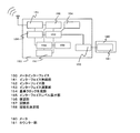
- FIG. 1 shows each block diagram of a concentrator corresponding to the upper terminal or the highest terminal and a meter interface corresponding to the lowest terminal according to the wireless communication system of the present invention.
- the system of the present invention includes a concentrator 100, a meter interface 150, and a meter 180. First, each block in FIG. 1 will be described.
- the concentrator 100 includes a long-range radio unit 101, a calculation unit 102, a short-range radio unit 103, a reference clock generation unit 104, a level calculation unit 105, and an installation information storage unit 106.
- the long-distance wireless unit 101 is configured with a device for performing long-distance communication.
- the arithmetic unit 102 controls to perform communication according to a predetermined protocol or specification between the two radio units.
- the short-range wireless unit 103 communicates with a meter interface 150 described later.
- the reference clock generation unit 104 generates a reference timing for communicating in synchronization with the meter interface 150 when performing communication.
- the level calculation unit 105 calculates the signal level of the signal transmitted from the meter interface 150 and received by the short-range radio unit 103.
- the installation information storage unit 106 stores, for example, information about the installation height, the surrounding situation, or the environment as the installation information of the concentrator 100.
- the meter interface 150 includes an interface wireless unit 151, an interface unit 152, an interface calculation unit 153, a reference clock generation unit 154, an interface level calculation unit 155, a demodulation unit 156, a storage unit 157, and a connection destination determination unit. 158.
- the interface wireless unit 151 communicates with the concentrator 100.
- the interface unit 152 reads the count counted by the counter unit 181 of the meter 180.
- the interface calculation unit 153 controls the interface unit 152 periodically, or controls the interface radio unit 151 with a predetermined sequence or protocol.
- the reference clock generation unit 154 generates a reference clock for performing synchronous communication with the concentrator 100.
- the interface level calculation unit 155 receives a signal from the concentrator 100 by the interface wireless unit 151 and calculates the signal level.
- the demodulator 156 generates demodulated data from the data processed by the interface radio unit 151 according to a predetermined protocol.
- the storage unit 157 stores a predetermined threshold (search condition threshold) related to a signal level for changing a search rule when the interface wireless unit 151 in the meter interface 150 searches for a concentrator 100 to be connected.
- the connection destination determination unit 158 determines an upper terminal to be connected to the meter interface 150 based on the signal level of the received signal, the number of lower terminals connected to the concentrator 100, and the like.
- the connection destination determination unit 158 makes the following determination.
- the concentrator with the smallest number of lower-level terminals connected to the concentrator is selected as the connection destination.
- the concentrator with the highest output value of the interface level calculation unit 155 Control to connect.
- the long-distance wireless unit 101 in the concentrator 100 is a wireless unit of a standard used in mobile phones and the like, for example, GSM (Global System for Mobile Communications), GPRS (General Packet Radio Service), EDGE (Enhanced Data GSM Environment). It is realized with a functional configuration such as The long-distance wireless unit 101 is connected to a management server via a public line or a network. With this management server, the status of the concentrator 100 can be monitored, operated, managed, and the like.
- GSM Global System for Mobile Communications
- GPRS General Packet Radio Service
- EDGE Enhanced Data GSM Environment
- the hardware configuration includes an antenna, a low noise amplifier, a detector, an oscillation circuit, a mixer, a phase synchronization circuit, a frequency divider, a demodulation circuit, a modulation circuit, a power amplifier, a voltage controlled oscillation circuit, and the above functions. It consists of a processor and the like.
- the short-range radio unit 103 is a communication part for communicating with the meter interface 150 connected to the lower level, with a transmission output equal to or smaller than that of the long-range radio unit 101.
- the configuration includes an antenna, a low noise amplifier, a detector, an oscillation circuit, a mixer, a phase synchronization circuit, a frequency divider, a demodulation circuit, a modulation circuit, a power amplifier, a voltage controlled oscillation circuit, and a processor having the above functions. Yes.
- the level calculation unit 105 includes an analog-digital conversion circuit, a comparator, a detection circuit, a clock circuit, and a calculation circuit in order to calculate the level of the signal received by the short-range radio unit 103.
- the installation information storage unit 106 is used to store installation information regarding the installation height, ambient conditions, environment, and the like of the concentrator 100, and includes a nonvolatile memory, a microcomputer, and the like.
- the arithmetic unit 102 controls the state of the concentrator in response to a command from the upper level received by the long-distance radio unit 101 of the concentrator 100, or the meter 180 of the meter 180 via the interface radio unit 151 of the lower level meter interface 150. Get information.
- the calculation unit 102 includes a microcomputer, a storage for storing data and programs, and the like.
- the reference clock generation unit 104 generates an oscillation circuit (for example, an oscillation composed of a crystal resonator, a ceramic resonator, a capacitor, a transistor, an inductor, etc.) in order to generate a reference clock necessary for performing synchronous communication with a meter interface or the like. Circuit) and a temperature correction circuit.
- an oscillation circuit for example, an oscillation composed of a crystal resonator, a ceramic resonator, a capacitor, a transistor, an inductor, etc.
- the interface wireless unit 151 in the meter interface 150 is a wireless unit for communicating with other short-range wireless devices including the concentrator 100.
- the configuration includes an antenna, a low noise amplifier, a detector, an oscillation circuit, a mixer, a phase synchronization circuit, a frequency divider, a modulation circuit, a power amplifier, a voltage control oscillation circuit, and a processor having the above functions.
- the reference clock generation unit 154 is a transmission circuit composed of a transmission circuit, for example, a crystal resonator, a ceramic resonator, a capacitor, a transistor, an inductor, etc., in order to generate a reference clock necessary for performing synchronous communication with a meter interface or the like.
- a circuit and the like and a temperature correction circuit are included.
- the interface unit 152 has a function of detecting the movement of the counter unit 181 in the meter 180.
- a sensor such as a reed switch, a coil, or an electrostatic sensor, a semiconductor element, or the like that detects the movement of the counter unit 181 is configured.
- the interface calculation unit 153 includes a microcomputer, a storage for storing data and programs, and the like.
- the interface level calculation unit 155 calculates a level of a signal received by the interface wireless unit 151 and transmitted from another wireless device, and is composed of an analog-digital conversion circuit, a detection circuit, a comparator, a microcomputer, and the like. ing.
- the demodulator 156 has a function for demodulating other signals received by the interface radio unit 151 according to a predetermined protocol or the like, and includes a waveform shaping circuit, a detection circuit, a level conversion circuit, a microcomputer, and the like. Yes.
- the storage unit 157 is configured by a non-volatile memory, a microcomputer, or the like so that the meter interface 150 stores a search condition threshold value that is changed when the concentrator 100 to be connected is searched.
- connection destination determination unit 158 compares the search condition threshold value stored in the storage unit 157 with the signal level output from the interface level calculation unit 155, and determines the search condition for the upper terminal to be connected. It consists of a computer.
- the meter 180 is a meter for managing energy consumption and flow rate, such as a gas meter, a water meter, a power meter, a current meter, a pressure meter, a flow meter, and a calorie meter.
- the counter unit 181 incorporates a sensor unit for counting consumption and flow rate, such as a flow rate sensor such as a pressure sensor, sputum, and ultrasonic wave.
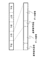
- FIG. 2 represents a time slot for the concentrator 100 and the meter interface 150 to communicate.
- Both the concentrator 100 and the meter interface 150 divide the time slot into an upper part and a lower part, and divide the time slot for transmission and the time slot for reception according to the time slot.
- the time slots of the concentrator 100 and the meter interface 150 are synchronized by a clock or the like possessed by each hardware, etc., and each time slot matches within a certain time, so that communication is performed. be able to.
- the time slot of the concentrator is divided into an upper part and a lower part, and the lower slot indicates a time slot for communicating with the meter interface 150 connected to the lower part of the concentrator.
- the upper part of the time slot of the meter interface 150 indicates a time slot when communicating with the concentrator to be connected.
- the concentrator is applied as the upper level and the meter interface is applied as the lower level, but there is no problem even if the higher and lower levels are switched.
- FIG. 3 shows the details of the time slot.
- the lower slot includes a reference signal transmission slot that is a time for transmitting a reference signal (for example, a beacon signal), and a data signal slot for transmitting and receiving a data signal (for example, a signal including telegram-like information). It is divided into
- the reference signal transmission slot is a time slot for transmitting a reference signal from the concentrator (higher-order device) to the meter interface (lower-order device). In this time slot, the concentrator transmits a predetermined reference signal.
- the data signal slot is a time slot for transmitting and receiving a telegram signal longer than the reference signal, for example, only when necessary, based on a specification predetermined between the concentrator and the meter interface.
- the upper slot is divided into a reference signal receiving slot for receiving a reference signal and a data signal slot for transmitting and receiving a data signal.
- the reference signal receiving slot is a time slot for receiving a reference signal transmitted from the concentrator (higher-order device) to the meter interface (lower-order device), and the meter interface periodically receives a predetermined reference signal.
- the data signal slot is a time slot for transmitting / receiving a signal in a telegram tone longer than the reference signal, for example, only when necessary based on a specification determined in advance between the concentrator and the meter interface.
- FIG. 4 summarizes the descriptions of FIGS. 2 and 3 for each time slot of the concentrator and meter interface.
- the time slot of the concentrator and the time slot of the meter interface are synchronized as shown in FIG.
- the concentrator transmits the reference signal toward the meter interface at the timing of the reference signal transmission slot of the lower slot.
- the meter interface receives the reference signal at the timing of the reference signal reception slot of the upper slot.
- communication occurs only when it is necessary to transmit / receive a data signal based on a predetermined specification.
- FIG. 5 shows a telegram configuration example of a data signal used in each time slot of the concentrator and meter interface shown in FIG.
- the bit synchronization pattern is a signal in which “0” and “1” alternate, and is positioned at the top of the message structure.
- the frame pattern is a data string for causing the concentrator and the meter interface to recognize that the message is used in the system according to the present invention, and is data unique to the system.
- the data pattern is data according to a predetermined protocol, for example, the identification ID of the device on the transmission side, the ID of the device (destination) on the side that receives the transmission signal, various control signals and information It is a data string including.
- the installation evaluation value of the higher-level device described later, the relay stage number information of the higher-level device, and the number information of the lower-level terminals already connected to the higher-level device are included.
- FIG. 6 is a diagram describing a mode in which a plurality of concentrators are provided as the wireless communication system according to the present embodiment.
- the system of the present embodiment is an environment in which three concentrators 100, 200, 300 and one meter interface 150 are placed. A method for searching for a concentrator with which the meter interface 150 communicates in this environment will be described.
- FIG. 7A is a diagram illustrating a sequence when the meter interface illustrated in FIG. 6 searches for a connected concentrate.
- FIG. 7B is a flowchart showing details of the connection terminal determination process in FIG. First, a procedure for searching for a concentrator to which the meter interface 150 is connected will be described with reference to FIG.
- the meter interface 150 shifts at a predetermined timing to a mode (search mode) for searching for a concentrator to be connected, which is different from a communication mode for transmitting and receiving normal meter reading values and flow rate abnormalities (S101).
- the predetermined timing can be set as appropriate. For example, it may be a time when an operator who installs the meter interface 150 inputs a predetermined operation to the meter interface 150, or a predetermined periodic timing. Alternatively, it may be a point in time when a state in which communication in the normal mode is disabled continues for a predetermined period.
- the meter interface 150 that has entered the search mode controls the interface wireless unit 151 to continuously receive for a predetermined time (S102). During the continuous reception period, the meter interface 150 receives the reference signal periodically transmitted from the concentrator by the interface radio unit 151 in the meter interface 150, and the interface level calculation unit 155 receives the RSSI (Received Signal Signal Strength Indicator). Convert to level to obtain the field strength level between the concentrator and meter interface 150.
- RSSI Receiveived Signal Signal Strength Indicator
- the interface level calculation unit 155 calculates the electric field intensity level (S103). Subsequently, the connection destination determination unit 158 reads the search condition threshold value stored in the storage unit 157 and compares it with the electric field intensity level calculated in S103 to determine which concentrator is connected (S104).
- the meter interface 150 determines whether or not reference signals are received from a plurality of concentrators, in other words, whether or not there are a plurality of acquired electric field strength levels (S104-1).
- the acquired electric field strength level is one.
- the concentrator that has transmitted the received reference signal is determined as the terminal to be connected (S104-2).
- the connection destination is determined as follows. That is, it is determined whether or not there is a field strength level that is equal to or higher than the search condition threshold among the plurality of acquired field strength levels (S104-3). If such a field strength level exists (S104-3: YES), a concentrator that transmits a reference signal indicating the field strength level and that has the smallest number of lower terminals already connected is selected. The terminal to be connected is determined (S104-4), and control is performed so as to connect to the terminal.
- connection is made with a concentrator having an electric field strength level lower than the search condition threshold.
- the terminal having the highest electric field strength level is determined as the terminal to be connected (S104-5).
- the terminal to be connected is determined based on the electric field strength level and the number of lower terminals already connected to the concentrator (S104-2, S104-4, S104-5), and the connected terminal determination process (S104). ).
- the concentrator to which the meter interface 150 is connected is determined by the process of S104, the meter interface 150 ends the search mode (S105).
- connection terminal is not limited to the procedure shown in this flowchart.
- the determination process of the connection terminal is not limited to the procedure shown in this flowchart.
- a concentrator that shows an electric field strength level that is equal to or higher than the search condition threshold select the one with the lowest number of connections from the lower terminals, and there is only a concentrator that shows an electric field strength level that is lower than the search condition threshold. If not, a concentrator with the highest electric field strength level may be selected from those, and a terminal connected to the selected concentrator may be determined.
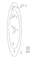
- FIG. 8 is a diagram schematically showing areas corresponding to respective electric field strength levels between the concentrator 100 and the meter interface A (150a), the meter interface B (150b), and the meter interface C (150c). .
- Area 1 (250) is an area that is considered to be surely successful when wireless communication is performed between the concentrator 100 and the meter interface A (150a) located in the area 1 (250). That is, fluctuation factors such as fading in the environment where each terminal is installed, the influence of the shielding, and noise in the surrounding environment, taking into account the specifications of the wireless devices of the concentrator 100 and the meter interface A (150a) In consideration of the above, and further considering a margin as necessary, an area where communication can be performed reliably is set as area 1 (250).
- the wireless device specifications referred to here include antenna performance, transmission output specifications, amplifier noise level specifications, reception sensitivity, and the like.
- Area 2 (260) is an area where communication is considered to be successful at a certain rate when the concentrator 100 communicates with the meter interface B (150b) located in the area 2 (260). This is, for example, an area where the communication success rate is not 100% due to fading and ambient noise. In addition, this area 2 (260) is not an area where communication cannot be performed completely. Even if communication fails, for example, retransmission control is performed using time diversity, or a route different from the route of the network constructed so far is used. This is an area where the communication success rate can be brought close to 100% by using the route diversity to be used or by using the antenna diversity.
- Area 3 (270) is an area where communication is hardly possible when the concentrator 100 and the meter interface C (150c) located in the area 3 (260) communicate with each other.
- the radio wave transmitted from each terminal is at a level equivalent to or lower than the ambient noise and the noise level existing in the wireless device itself, and it is difficult to expect successful communication.
- the search condition threshold value is a numerical value representing the boundary between the above-described area 1 (250) and area 2 (260). Therefore, when the meter interface searches for the concentrator 100 to be connected, if there are a plurality of devices showing the electric field intensity level equal to or higher than the search condition threshold, that is, if there are a plurality of concentrators located in the area 1 (250), Considering only the above, regardless of which concentrator is selected, the communication success rate is 100%. Accordingly, not only based on the communication success rate but also based on the number of meter interfaces (lower terminals) already connected to the concentrator 100 that is the upper terminal (see step S104-4 in FIG. 7B), etc.
- the connection destination can be selected under the conditions.
- the concentrator that can communicate at a certain success rate ie, the communication success rate is not 100%.
- the communication success rate is not 100%.
- it is desirable to select a concentrator having the highest electric field strength level see step S104-5 in FIG. 7B).
- meter interface A 150a
- meter interface B 150b
- meter interface C 150c
- each meter interface receives the reference signal transmitted from each of the three concentrators by the interface radio unit 151, and based on the received reference signal, the interface level calculation unit 155 determines the electric field strength level ( The result of calculating (RSSI level) is also shown.
- Meter interface A (150a) calculated RSSI based on the reference signal received from each concentrator, and obtained values 6, 7, and 9 from concentrators 100, 200, and 300, respectively.
- the search condition threshold value stored in advance in the storage unit 157 of the meter interface A (150a) is “5”, and all the obtained RSSIs are equal to or greater than the search condition threshold value (S104-3 in FIG. 7B). See YES). Therefore, the connection destination determination unit 158 in the meter interface A (150a) obtains information on the number of connections with lower-order terminals included in the information related to the data signal transmitted from the concentrator.
- the number of subordinate terminals to which each concentrator is already connected is 200 for the concentrator A (100), 500 for the concentrator B (200), and 600 for the concentrator C (300). Therefore, the meter interface A (150a) performs control so as to connect to the concentrator A (100) having the smallest number of lower-level terminals already connected (see S104-4 in FIG. 7B).
- the RSSI obtained from each concentrator is 5 for the concentrator A (100), 4 for the concentrator B (200), and 3 for the concentrator C (300).
- the RSSI obtained from each concentrator is 3 for the concentrator A (100), 4 for the concentrator B (200), and 2 for the concentrator C (300).
- the search condition threshold value is 5, and there is no concentrator satisfying this condition (see NO in S104-3 in FIG. 7B). Therefore, the concentrator B (200) with the maximum RSSI is selected as the connection destination (see S104-5 in FIG. 7B).
- a terminal that has been able to determine a search route with a search condition threshold value or higher can reliably perform time diversity, route diversity, antenna diversity control, and the like. Since there is a high possibility of communication, the control can be omitted.
- the meter interface according to the present embodiment preferably has a configuration capable of executing one or more of the various diversity functions described above.
- the upper terminal search rule is changed based on the RSSI level of the signal from the upper terminal. ing.
- the communication area of the system can be expanded, and a robust communication route can be established by combining each diversity.
- control for ensuring robustness can be omitted, which can contribute to reduction of traffic and power consumption.
- each terminal can build a route with only installed terminals, even if not all terminals of the entire system are installed. The degree of freedom increases.
- the above method can be applied in the same manner even when a repeater that plays a role of relay is included in communication between the concentrator and the meter interface. That is, if the concentrator is positioned as an upper terminal and the repeater is positioned as a lower terminal, the above method can be adopted in connection destination search between the upper terminal and the lower terminal. Similarly, in each of the connection destination search between the repeater serving as the upper terminal and the meter interface serving as the lower terminal, and then the connection destination search between the repeater serving as the upper terminal and the repeater serving as the lower terminal, The method can be adopted.
- Embodiment 2 Next, a route search method in a wireless communication system including a concentrator, a repeater, and a meter interface will be described. Here, a different part from Embodiment 1 is demonstrated.
- the concentrator is assumed to have the configuration shown in FIG. First, the internal configuration of the repeater and the meter interface will be described with reference to FIGS. 10 and 11.
- FIG. 10 shows an internal block diagram of the repeater.
- the repeater functions include relaying communication between the concentrator and the meter interface to secure a communication path, and amplifying the radio wave intensity reduced by the shadow wing.
- the repeater 400 includes a repeater radio unit 401, a repeater level calculation unit 405, a repeater demodulation unit 406, a repeater calculation unit 453, a reference clock generation unit 454, a repeater storage unit 457, and a repeater connection destination determination unit 458. It is configured.
- the repeater wireless unit 401 communicates with a concentrator and a meter interface.
- the repeater level calculation unit 405 receives a signal transmitted from the concentrator or the meter interface by the repeater wireless unit 401 and calculates the signal level.
- the repeater demodulating unit 406 performs demodulation using a predetermined protocol or specification communication among the concentrator, meter interface, and repeater.
- the repeater calculation unit 453 controls communication of the repeater itself based on the output of the repeater demodulation unit 406.
- the reference clock generation unit 454 generates reference timing for communicating in synchronization with each terminal.
- the repeater storage unit 457 stores a threshold value (search condition threshold value) that serves as a reference for whether or not to change the search condition when searching for a communication route in the wireless communication between the concentrator or another repeater and the repeater 150. Is.
- the repeater storage unit 457 may store the number of relay stages from the concentrator, which is the highest terminal, to the own device as installation information.
- the repeater connection destination determination unit 458 determines the upper terminal to be connected to the own device (repeater 400) based on the electric field strength level of the signal from the upper terminal and the current number of relay stages of the upper terminal.
- the repeater 400 calculates the electric field strength level of each signal by the repeater level calculator 405 based on a plurality of signals transmitted from a plurality of higher-level terminals such as a concentrator and other repeaters. To do. Then, the connection destination is determined by comparing the calculated electric field strength level with the threshold value stored in the repeater storage unit 457.
- the repeater connection destination determination unit 458 determines that the upper terminal is based on the installation information transmitted from the upper terminal (concentrator, repeater). Is selected as the connection destination, and if there is only one having a field strength level smaller than the threshold, the upper terminal having the maximum field strength level is selected as the connection destination.
- the repeater wireless unit 401 in the repeater 400 is a wireless unit for communicating with other short-range wireless devices including a concentrator and a meter interface.
- the configuration includes an antenna, a low noise amplifier, a detector, an oscillation circuit, a mixer, a phase synchronization circuit, a frequency divider, a demodulation circuit, a modulation circuit, a power amplifier, a voltage controlled oscillation circuit, and a processor having the above functions.
- the hardware specification shared between the concentrator and the repeater and the hardware specification shared between the repeater and the meter interface do not have to be the same.
- a band that can use a high transmission output is used to increase the distance, and in the specification between the repeater and the meter interface, it is relatively low in order to emphasize power saving. It is good also as communicating by reducing an output in a frequency band.
- the reference clock generation unit 454 generates an oscillation circuit (for example, an oscillation composed of a crystal resonator, a ceramic resonator, a capacitor, a transistor, an inductor, etc.) in order to generate a reference clock necessary for performing synchronous communication with a meter interface or the like. Circuit) and a temperature correction circuit.
- an oscillation circuit for example, an oscillation composed of a crystal resonator, a ceramic resonator, a capacitor, a transistor, an inductor, etc.
- the connection destination determination unit 158 of the meter interface 150 in FIG. 11 includes a search condition threshold value stored in advance in the storage unit 157, and an electric field strength level generated from a reference signal transmitted from a concentrator or repeater that is a higher-level terminal. Compare When there are a plurality of electric field intensity levels equal to or higher than the search condition threshold, the connection destination is determined based on the installation information transmitted from the higher order terminal (concentrator, repeater). That is, based on the installation information, a connection destination candidate upper terminal having the smallest number of relay stages is selected as a connection destination. On the other hand, if there is only an electric field strength level less than the search condition threshold, an upper terminal having the maximum electric field strength level is selected as the connection destination.
- the installation information referred to here is information regarding the number of stages relayed from the highest level concentrator to the corresponding higher order terminal in the terminal where the route has already been formed.
- the data can be stored in the repeater storage unit 457 included in the repeater 400.
- the meter interface shifts at a predetermined timing to a mode (search mode) for searching for a concentrator to be connected, which is different from a communication mode for transmitting and receiving normal meter reading values, flow rate abnormalities, and the like (S201).
- This timing may be the same as the predetermined timing described in the first embodiment, or another timing may be adopted.
- the meter interface that has entered the search mode controls the interface wireless unit 151 to continuously receive for a predetermined time (S202).
- the meter interface receives the reference signal periodically transmitted from the repeater by the interface radio unit 151 in the meter interface 150, converts the reference signal to the RSSI level by the interface level calculation unit 155, The electric field strength level with the meter interface 150 is acquired.
- the signal transmitted from the repeater is demodulated to obtain the installation information of the repeater (S203).
- the installation information includes the number of relay stages, which is the number of terminals relayed when communicating with the concentrator through the repeater.
- the meter interface determines whether or not reference signals are received from a plurality of repeaters, in other words, whether or not there are a plurality of acquired electric field strength levels (S204-1).
- the acquired electric field strength level is one.
- the repeater that has transmitted the received reference signal is determined as the terminal to be connected (S204-2).
- the connection destination is determined as follows. That is, it is determined whether or not there is an electric field intensity level equal to or higher than the search condition threshold value among the plurality of acquired electric field intensity levels (S204-3). If such a field strength level exists (S204-3: YES), a repeater having the smallest number of relay stages is selected from repeaters that transmit a reference signal indicating the field strength level based on the installation information. The terminal to be connected is determined (S204-4).
- the repeater having the maximum RSSI level is determined as the terminal to be connected (S204-5).
- the terminal to be connected is determined (S204-2, S204-4, S204-5), and the determination process of the connected terminal (S204) is completed.
- the meter interface 150 ends the search mode (S205).
- the search condition threshold value of the meter interface A (150a) is “6”, and the RSSI level obtained from the repeater B (410) and the repeater C (420) is larger. Therefore, the meter interface A (150a) performs control to select the repeater C (420) having a small number of relay stages as a connection destination (see S204-4 in FIG. 12B).
- the meter interface B (150b) receives the signals of the repeater E (440) and the repeater F (450) by searching for a connectable repeater (by continuously receiving the reference signal) in the search mode.
- the RSSI level obtained from each repeater is 5 for the repeater E (440) and 3 for the repeater F (450), and the RSSI value obtained from each repeater is more than the connection condition threshold “6” of the meter interface B. Is a small value.
- the terminal having the maximum RSSI level is selected regardless of repeater installation information (such as the number of relay stages) (see S204-5 in FIG. 12B). . Accordingly, the repeater E (440) is selected here.
- the route search example between the meter interface and the repeater has been explained.
- the same method can be used when searching for a route between a repeater and a repeater that has multiple stages, or when searching for a route connected from the meter interface to the concentrator. can do.
- the communication route between each terminal determined in this way has a high communication success rate when searching at or above the search condition threshold, so it is possible to omit communication retransmission control and antenna diversity control in advance, and only communication robustness In addition, power consumption can be reduced.
- the success rate of communication can be increased and the communication area can be expanded by using time diversity, antenna diversity, and route diversity.
- the same method as described above can be adopted even when the repeater determines the connection destination from among a plurality of repeaters located at the upper level, but it is not limited to such a configuration.
- the repeater may be limited to a repeater having a field intensity level equal to or higher than a search condition threshold.
- the connection terminal determination process in this case is shown in the flowchart of FIG.
- the repeater connection destination determination unit 458 of the repeater 400 determines whether or not there is an acquired electric field intensity level that is equal to or higher than the search condition threshold (S301).
- the search condition threshold S301: YES
- the one having the smallest number of relay stages is determined as the connection destination from such electric field strength levels (S302).
- S301: NO the search condition threshold
- no terminal is selected as a connection destination (S303), and this connection terminal determination process is terminated.
- a wireless communication system using a repeater that performs such a connected terminal determination process and a meter interface that performs such a connected terminal determination process as shown in FIG. 7B or 12B.
- a repeater that performs such a connected terminal determination process and a meter interface that performs such a connected terminal determination process as shown in FIG. 7B or 12B.
- the meter interface communication robustness, power saving, and expansion of the communication area as described above can be expected.
- the reliability of repeater communication can be improved by adopting a configuration in which only a terminal having a search condition threshold value or more is connected.
- the wireless device can expand the communication area while ensuring the robustness of communication with respect to the connected wireless device.
Abstract
Priority Applications (5)
| Application Number | Priority Date | Filing Date | Title |
|---|---|---|---|
| CN201180043509.9A CN103098518B (zh) | 2010-09-09 | 2011-03-09 | 无线通信系统 |
| US13/808,546 US20130109397A1 (en) | 2010-09-09 | 2011-03-09 | Radio device |
| EP11773165.3A EP2451216B1 (fr) | 2010-09-09 | 2011-03-09 | Dispositif sans fil |
| ES11773165.3T ES2545509T3 (es) | 2010-09-09 | 2011-03-09 | Dispositivo inalámbrico |
| JP2012532833A JP5877385B2 (ja) | 2010-09-09 | 2011-03-09 | 無線通信システム |
Applications Claiming Priority (2)
| Application Number | Priority Date | Filing Date | Title |
|---|---|---|---|
| JP2010-201648 | 2010-09-09 | ||
| JP2010201648 | 2010-09-09 |
Publications (1)
| Publication Number | Publication Date |
|---|---|
| WO2012032683A1 true WO2012032683A1 (fr) | 2012-03-15 |
Family
ID=45810297
Family Applications (1)
| Application Number | Title | Priority Date | Filing Date |
|---|---|---|---|
| PCT/JP2011/001388 WO2012032683A1 (fr) | 2010-09-09 | 2011-03-09 | Dispositif sans fil |
Country Status (6)
| Country | Link |
|---|---|
| US (1) | US20130109397A1 (fr) |
| EP (1) | EP2451216B1 (fr) |
| JP (1) | JP5877385B2 (fr) |
| CN (1) | CN103098518B (fr) |
| ES (1) | ES2545509T3 (fr) |
| WO (1) | WO2012032683A1 (fr) |
Cited By (6)
| Publication number | Priority date | Publication date | Assignee | Title |
|---|---|---|---|---|
| WO2012147353A1 (fr) * | 2011-04-28 | 2012-11-01 | パナソニック株式会社 | Système de communication sans fil, terminal sans fil, procédé permettant de commander un terminal sans fil et programme permettant de commander un terminal sans fil |
| JP2013183382A (ja) * | 2012-03-02 | 2013-09-12 | Nec Access Technica Ltd | 無線通信装置、無線通信システム、無線通信方法および無線通信プログラム |
| JP2016072782A (ja) * | 2014-09-30 | 2016-05-09 | 株式会社日立製作所 | 自動検針システム及び自動検針データの通信方法 |
| JP2018113579A (ja) * | 2017-01-11 | 2018-07-19 | 太陽誘電株式会社 | 無線接続装置 |
| WO2019230522A1 (fr) * | 2018-06-01 | 2019-12-05 | パナソニックIpマネジメント株式会社 | Terminal de communication, système de communication et programme de communication |
| WO2019230521A1 (fr) * | 2018-06-01 | 2019-12-05 | パナソニックIpマネジメント株式会社 | Terminal de communication, système de communication et programme de communication |
Families Citing this family (4)
| Publication number | Priority date | Publication date | Assignee | Title |
|---|---|---|---|---|
| US10136341B2 (en) * | 2017-01-03 | 2018-11-20 | Simmonds Precision Products, Inc. | Wireless data concentrator systems and methods |
| CN106600941A (zh) * | 2017-02-15 | 2017-04-26 | 南通德高环境监测技术有限公司 | 一种低功耗无线自组网抄表系统 |
| CN107613541B (zh) * | 2017-09-08 | 2021-06-22 | 深圳市盛路物联通讯技术有限公司 | 中转节点的设备挂载控制系统及中转节点 |
| JP2022092384A (ja) * | 2020-12-10 | 2022-06-22 | トヨタ自動車株式会社 | 情報処理装置、通信システム、選択方法及びプログラム |
Citations (5)
| Publication number | Priority date | Publication date | Assignee | Title |
|---|---|---|---|---|
| JPH11168526A (ja) | 1997-12-04 | 1999-06-22 | Omron Corp | 無線ネットワーク中継管理方法および装置 |
| JP2002325273A (ja) * | 2001-02-21 | 2002-11-08 | Nippon Telegr & Teleph Corp <Ntt> | 無線通信システム、無線通信方法及び無線局 |
| JP2003030772A (ja) * | 2001-07-13 | 2003-01-31 | Mitsubishi Electric Corp | 自動検針システムおよびデータ収集システム |
| JP2006081164A (ja) * | 2004-08-11 | 2006-03-23 | Iwatsu Electric Co Ltd | Lanシステム及び無線lanのエリア拡張方法、並びにそのためのアクセスポイント及びステーション |
| JP2007335994A (ja) | 2006-06-12 | 2007-12-27 | Toshiba Corp | 無線通信装置及び送信制御方法 |
Family Cites Families (6)
| Publication number | Priority date | Publication date | Assignee | Title |
|---|---|---|---|---|
| JP3084066B2 (ja) * | 1993-12-24 | 2000-09-04 | インターナシヨナル・ビジネス・マシーンズ・コーポレーシヨン | 情報ネットワークにおける帯域幅予約接続の経路指定 |
| US7020087B2 (en) * | 2003-01-13 | 2006-03-28 | Motorola, Inc. | Segmented and distributed path optimization in a communication network |
| EP1626537A1 (fr) * | 2004-08-11 | 2006-02-15 | Iwatsu Electric Co., Ltd. | Système de réseau local sans fil et procédé correspondant pour connexion de points d'accès |
| JP4316593B2 (ja) * | 2006-09-04 | 2009-08-19 | 日本電気通信システム株式会社 | 無線装置およびそれを備えた無線通信ネットワーク |
| JP4352180B2 (ja) * | 2006-11-16 | 2009-10-28 | 株式会社カシオ日立モバイルコミュニケーションズ | 無線通信ハンドオーバ処理方法、携帯型電子装置、無線通信ハンドオーバシステム |
| US8121053B2 (en) * | 2007-05-21 | 2012-02-21 | Arrowspan, Inc. | Multi-radio wireless mesh network solutions |
-
2011
- 2011-03-09 CN CN201180043509.9A patent/CN103098518B/zh not_active Expired - Fee Related
- 2011-03-09 EP EP11773165.3A patent/EP2451216B1/fr not_active Not-in-force
- 2011-03-09 ES ES11773165.3T patent/ES2545509T3/es active Active
- 2011-03-09 WO PCT/JP2011/001388 patent/WO2012032683A1/fr active Application Filing
- 2011-03-09 US US13/808,546 patent/US20130109397A1/en not_active Abandoned
- 2011-03-09 JP JP2012532833A patent/JP5877385B2/ja active Active
Patent Citations (5)
| Publication number | Priority date | Publication date | Assignee | Title |
|---|---|---|---|---|
| JPH11168526A (ja) | 1997-12-04 | 1999-06-22 | Omron Corp | 無線ネットワーク中継管理方法および装置 |
| JP2002325273A (ja) * | 2001-02-21 | 2002-11-08 | Nippon Telegr & Teleph Corp <Ntt> | 無線通信システム、無線通信方法及び無線局 |
| JP2003030772A (ja) * | 2001-07-13 | 2003-01-31 | Mitsubishi Electric Corp | 自動検針システムおよびデータ収集システム |
| JP2006081164A (ja) * | 2004-08-11 | 2006-03-23 | Iwatsu Electric Co Ltd | Lanシステム及び無線lanのエリア拡張方法、並びにそのためのアクセスポイント及びステーション |
| JP2007335994A (ja) | 2006-06-12 | 2007-12-27 | Toshiba Corp | 無線通信装置及び送信制御方法 |
Non-Patent Citations (1)
| Title |
|---|
| See also references of EP2451216A4 |
Cited By (11)
| Publication number | Priority date | Publication date | Assignee | Title |
|---|---|---|---|---|
| WO2012147353A1 (fr) * | 2011-04-28 | 2012-11-01 | パナソニック株式会社 | Système de communication sans fil, terminal sans fil, procédé permettant de commander un terminal sans fil et programme permettant de commander un terminal sans fil |
| JP2013183382A (ja) * | 2012-03-02 | 2013-09-12 | Nec Access Technica Ltd | 無線通信装置、無線通信システム、無線通信方法および無線通信プログラム |
| JP2016072782A (ja) * | 2014-09-30 | 2016-05-09 | 株式会社日立製作所 | 自動検針システム及び自動検針データの通信方法 |
| JP2018113579A (ja) * | 2017-01-11 | 2018-07-19 | 太陽誘電株式会社 | 無線接続装置 |
| WO2019230522A1 (fr) * | 2018-06-01 | 2019-12-05 | パナソニックIpマネジメント株式会社 | Terminal de communication, système de communication et programme de communication |
| WO2019230521A1 (fr) * | 2018-06-01 | 2019-12-05 | パナソニックIpマネジメント株式会社 | Terminal de communication, système de communication et programme de communication |
| JP2019213009A (ja) * | 2018-06-01 | 2019-12-12 | パナソニックIpマネジメント株式会社 | 通信端末、通信システム、及びプログラム |
| JP2019213008A (ja) * | 2018-06-01 | 2019-12-12 | パナソニックIpマネジメント株式会社 | 通信端末、通信システム、及びプログラム |
| TWI726323B (zh) * | 2018-06-01 | 2021-05-01 | 日商松下知識產權經營股份有限公司 | 通信終端、通信系統及記錄媒體 |
| JP7117549B2 (ja) | 2018-06-01 | 2022-08-15 | パナソニックIpマネジメント株式会社 | 通信端末、通信システム、及びプログラム |
| JP7266233B2 (ja) | 2018-06-01 | 2023-04-28 | パナソニックIpマネジメント株式会社 | 通信端末、通信システム、及びプログラム |
Also Published As
| Publication number | Publication date |
|---|---|
| EP2451216A4 (fr) | 2012-12-26 |
| EP2451216B1 (fr) | 2015-06-10 |
| CN103098518A (zh) | 2013-05-08 |
| JPWO2012032683A1 (ja) | 2013-12-12 |
| JP5877385B2 (ja) | 2016-03-08 |
| US20130109397A1 (en) | 2013-05-02 |
| ES2545509T3 (es) | 2015-09-11 |
| CN103098518B (zh) | 2016-04-27 |
| EP2451216A1 (fr) | 2012-05-09 |
Similar Documents
| Publication | Publication Date | Title |
|---|---|---|
| JP5877385B2 (ja) | 無線通信システム | |
| JP6206741B2 (ja) | 無線通信システム、無線端末、無線端末の制御方法、および無線端末の制御プログラム | |
| US6970714B2 (en) | Adaptive power level setting in an ad-hoc wireless network | |
| US8140003B2 (en) | Method and apparatus for supporting multi-hop communications in a peer to peer communication system | |
| JP5297220B2 (ja) | 自動検針無線システム及びこれに用いられる無線通信端末装置 | |
| JPWO2003101132A1 (ja) | 移動通信システム、送信局、受信局、中継局、通信経路決定方法および通信経路決定プログラム | |
| JP2017152855A (ja) | 無線通信装置、無線通信方法およびプログラム | |
| WO2011037214A1 (fr) | Station de base, station terminale, système radio, procédé de contrôle radio, et support de stockage | |
| US20130208598A1 (en) | Communication system, control device, and node device | |
| JP2011055374A (ja) | 無線装置、無線通信システムおよび無線通信方法 | |
| JP2008301268A (ja) | 通信ルートの探索方法およびそれを用いる通信端末 | |
| EP2833643B1 (fr) | Dispositif de communication, système de gestion d'énergie comprenant un dispositif de communication, et procédé de commande de dispositif de communication | |
| JP2015088807A (ja) | 無線通信装置及び無線情報収集システム | |
| JP6459195B2 (ja) | 無線ネットワークシステム、無線ネットワークシステムの通信制御方法、制御装置、ネットワークエレメント、及び、通信制御プログラム | |
| JP5651527B2 (ja) | 無線端末装置、無線通信システム、プログラムおよび無線通信方法 | |
| JP5796179B2 (ja) | 通信装置 | |
| WO2016021105A1 (fr) | Appareil radio | |
| JP6351059B2 (ja) | 無線通信端末 | |
| JP6221050B2 (ja) | 無線通信システム、無線端末、及び通信方法 | |
| JP6824488B1 (ja) | 通信端末、通信装置、通信管理装置、通信システム、ネットワーク参入方法およびネットワーク参入プログラム | |
| JP6004737B2 (ja) | 小規模基地局およびその通信システム | |
| JP5904579B2 (ja) | 通信システム、通信制御方法、ノード装置、ノード装置制御方法、及び、ノード装置制御プログラム | |
| JP2017130850A (ja) | 通信装置 |
Legal Events
| Date | Code | Title | Description |
|---|---|---|---|
| WWE | Wipo information: entry into national phase |
Ref document number: 201180043509.9 Country of ref document: CN |
|
| WWE | Wipo information: entry into national phase |
Ref document number: 2011773165 Country of ref document: EP |
|
| 121 | Ep: the epo has been informed by wipo that ep was designated in this application |
Ref document number: 11773165 Country of ref document: EP Kind code of ref document: A1 |
|
| WWE | Wipo information: entry into national phase |
Ref document number: 2012532833 Country of ref document: JP |
|
| WWE | Wipo information: entry into national phase |
Ref document number: 13808546 Country of ref document: US |
|
| NENP | Non-entry into the national phase |
Ref country code: DE |