WO2012023393A1 - エンジン始動装置 - Google Patents
エンジン始動装置 Download PDFInfo
- Publication number
- WO2012023393A1 WO2012023393A1 PCT/JP2011/067121 JP2011067121W WO2012023393A1 WO 2012023393 A1 WO2012023393 A1 WO 2012023393A1 JP 2011067121 W JP2011067121 W JP 2011067121W WO 2012023393 A1 WO2012023393 A1 WO 2012023393A1
- Authority
- WO
- WIPO (PCT)
- Prior art keywords
- pinion gear
- pinion
- gear
- engine
- engine starter
- Prior art date
Links
Images


Classifications
-
- F—MECHANICAL ENGINEERING; LIGHTING; HEATING; WEAPONS; BLASTING
- F02—COMBUSTION ENGINES; HOT-GAS OR COMBUSTION-PRODUCT ENGINE PLANTS
- F02N—STARTING OF COMBUSTION ENGINES; STARTING AIDS FOR SUCH ENGINES, NOT OTHERWISE PROVIDED FOR
- F02N11/00—Starting of engines by means of electric motors
-
- F—MECHANICAL ENGINEERING; LIGHTING; HEATING; WEAPONS; BLASTING
- F02—COMBUSTION ENGINES; HOT-GAS OR COMBUSTION-PRODUCT ENGINE PLANTS
- F02N—STARTING OF COMBUSTION ENGINES; STARTING AIDS FOR SUCH ENGINES, NOT OTHERWISE PROVIDED FOR
- F02N15/00—Other power-operated starting apparatus; Component parts, details, or accessories, not provided for in, or of interest apart from groups F02N5/00 - F02N13/00
- F02N15/02—Gearing between starting-engines and started engines; Engagement or disengagement thereof
- F02N15/04—Gearing between starting-engines and started engines; Engagement or disengagement thereof the gearing including disengaging toothed gears
- F02N15/06—Gearing between starting-engines and started engines; Engagement or disengagement thereof the gearing including disengaging toothed gears the toothed gears being moved by axial displacement
-
- F—MECHANICAL ENGINEERING; LIGHTING; HEATING; WEAPONS; BLASTING
- F02—COMBUSTION ENGINES; HOT-GAS OR COMBUSTION-PRODUCT ENGINE PLANTS
- F02N—STARTING OF COMBUSTION ENGINES; STARTING AIDS FOR SUCH ENGINES, NOT OTHERWISE PROVIDED FOR
- F02N15/00—Other power-operated starting apparatus; Component parts, details, or accessories, not provided for in, or of interest apart from groups F02N5/00 - F02N13/00
- F02N15/02—Gearing between starting-engines and started engines; Engagement or disengagement thereof
- F02N15/022—Gearing between starting-engines and started engines; Engagement or disengagement thereof the starter comprising an intermediate clutch
- F02N15/023—Gearing between starting-engines and started engines; Engagement or disengagement thereof the starter comprising an intermediate clutch of the overrunning type
-
- F—MECHANICAL ENGINEERING; LIGHTING; HEATING; WEAPONS; BLASTING
- F02—COMBUSTION ENGINES; HOT-GAS OR COMBUSTION-PRODUCT ENGINE PLANTS
- F02N—STARTING OF COMBUSTION ENGINES; STARTING AIDS FOR SUCH ENGINES, NOT OTHERWISE PROVIDED FOR
- F02N15/00—Other power-operated starting apparatus; Component parts, details, or accessories, not provided for in, or of interest apart from groups F02N5/00 - F02N13/00
- F02N15/02—Gearing between starting-engines and started engines; Engagement or disengagement thereof
- F02N15/04—Gearing between starting-engines and started engines; Engagement or disengagement thereof the gearing including disengaging toothed gears
- F02N15/06—Gearing between starting-engines and started engines; Engagement or disengagement thereof the gearing including disengaging toothed gears the toothed gears being moved by axial displacement
- F02N15/067—Gearing between starting-engines and started engines; Engagement or disengagement thereof the gearing including disengaging toothed gears the toothed gears being moved by axial displacement the starter comprising an electro-magnetically actuated lever
-
- Y—GENERAL TAGGING OF NEW TECHNOLOGICAL DEVELOPMENTS; GENERAL TAGGING OF CROSS-SECTIONAL TECHNOLOGIES SPANNING OVER SEVERAL SECTIONS OF THE IPC; TECHNICAL SUBJECTS COVERED BY FORMER USPC CROSS-REFERENCE ART COLLECTIONS [XRACs] AND DIGESTS
- Y10—TECHNICAL SUBJECTS COVERED BY FORMER USPC
- Y10T—TECHNICAL SUBJECTS COVERED BY FORMER US CLASSIFICATION
- Y10T74/00—Machine element or mechanism
- Y10T74/13—Machine starters
- Y10T74/131—Automatic
- Y10T74/137—Reduction gearing
Definitions
- the present invention relates to an improvement in meshability between a pinion gear in a starter at the time of engine start and an engine ring gear.
- a conventional engine starter (hereinafter referred to as a starter) performs a start operation while the engine is stopped. Therefore, the pinion gear is engaged with the ring gear while the ring gear is not rotating.
- a starter performs a start operation while the engine is stopped. Therefore, the pinion gear is engaged with the ring gear while the ring gear is not rotating.
- restartability is ensured by engaging the pinion gear with the ring gear even while the ring gear is rotating.
- the ring gear decelerates by inertial rotation after the engine is stopped.
- the ring gear stops while the rotation speed pulsates due to torque fluctuation caused by compression and expansion of the piston. Therefore, for example, as in Patent Document 1, a complicated configuration is required to synchronize the rotation speeds of the ring gear and the pinion gear with an engine starter (starter) and mesh them.
- a complicated configuration is required in which the rotation speeds of the ring gear and the pinion gear are acquired or predicted, and based on these, the starter is controlled and meshed.
- the rotation speed of the ring gear and the pinion gear can be reduced with a simpler structure by bringing the pinion gear and the ring gear into contact with each other with a synchronization mechanism in advance. Can be synchronized.
- the pinion gear and the ring gear usually have a gear ratio of 10 times for miniaturization of the motor, and are not coaxial due to restrictions on dimensional configuration. Therefore, the friction surface of the synchro mechanism that is brought into contact with the ring gear from the pinion gear is always synchronized with slipping, and it is difficult to achieve complete synchronization that matches the phase.
- the present invention was made to solve such a problem, and even when the pinion gear meshes with the ring gear during the rotation of the ring gear, more reliable synchronization and phase alignment are performed at the moment of contact, It is an object of the present invention to provide an engine starter that suppresses start-up delay due to noise, wear reduction due to wear, and loss of meshing time.
- An engine starter has a starter motor, a pinion portion that is axially slid connected to the output shaft side of the starter motor, and an extrusion mechanism that moves the pinion portion to a meshing position with a ring gear.
- the pinion portion has a protruding shape for synchronization.
- the first pinion gear that first collides with the ring gear at the start of meshing with the ring gear and the second pinion gear that serves to transmit the rotational force after meshing have a pinion gear divided into two in the axial direction It is.
- the pinion gear of the pinion portion is divided into a first pinion gear having a synchronous tooth shape at the tip and a second pinion gear that plays a role of transmitting rotational force after meshing. Even when there is a difference in rotation speed, it is possible to stably mesh the pinion and the ring gear. Even when the pinion gear is meshed while the ring gear is rotating, more reliable synchronization and phase alignment are brought into contact. It is possible to obtain an engine starting device that is instantaneously performed and that does not cause a delay in starting performance due to noise, a decrease in life due to wear, and a loss of engagement time.
- Embodiment 1 of the present invention It is an exploded view of the engine starting device in Embodiment 1 of the present invention. It is sectional drawing at the time of attaching the engine starting device in Embodiment 1 of this invention to an engine. It is an exploded view of the component of the pinion part in Embodiment 1 of this invention. It is a detailed perspective view of the 1st pinion gear and the 2nd pinion gear by Embodiment 1 of this invention. It is sectional drawing of the starter part in the moment when the 1st pinion gear and ring gear collided with Embodiment 1 of the present invention. It is a figure which shows the positional relationship seen from the front of the 1st pinion gear and the 2nd pinion gear by Embodiment 1 of this invention.
- FIG. 8 is a cross-sectional view of the starter portion in a state in which a ring gear is inserted into the first pinion gear and abuts against the second pinion gear through the state of FIG. 7 according to the first embodiment of the present invention.
- FIG. 9 is a cross-sectional view of the starter unit in which the ring gear is inserted into the first pinion gear and the second pinion gear through the state of FIGS. It is a perspective view in which the 1st pinion gear by Embodiment 1 of the present invention is constituted by projection.
- Embodiment 2 of this invention It is an exploded view of the component of the pinion part in Embodiment 2 of this invention. It is a detailed perspective view of the 1st pinion gear and the 2nd pinion gear by Embodiment 2 of this invention. It is a figure which shows the positional relationship seen from the front of the 1st pinion gear by the Embodiment 2 of this invention, and a 2nd pinion gear. It is an exploded view of the component of the pinion part in Embodiment 3 of this invention. It is an exploded view of the component of the pinion part in Embodiment 4 of this invention. It is sectional drawing of the starter part before the 1st pinion gear and ring gear by Embodiment 4 of this invention collide. It is sectional drawing of the starter part of the state which the 1st pinion gear and ring gear collide with Embodiment 4 of this invention, and the 1st pinion gear inclines.
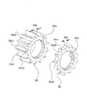
- FIG. 1 is an exploded view of an engine starter according to Embodiment 1 of the present invention.
- the engine starter in the first embodiment shown in FIG. 1 includes a motor driving force unit 10, a shaft 20, a pinion unit 30, a suction coil unit 40, a plunger 50, a lever 60, a bracket 70, a stopper 80, and a reduction gear unit 90. It is configured.
- the motor driving force unit 10 starts the engine.
- the shaft 20 is coupled to the output shaft side of the motor via a reduction gear unit 90.
- the pinion portion 30 is integrated with an overrunning clutch that is helically splined to the shaft 20 and can slide in the axial direction.
- the suction coil unit 40 sucks the plunger 50 by turning on the switch.
- the lever 60 transmits the movement of the plunger 50 by suction to the pinion unit 30.
- the bracket 70 fixes each component including the motor driving force portion 10, the shaft 20, and the pinion portion 30 to the engine side via a stopper 80 when the pinion moves.
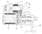
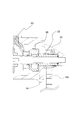
- FIG. 2 is a cross-sectional view when the engine starter according to Embodiment 1 of the present invention is attached to the engine.
- the switch When the engine is started, when the switch is turned on, the relay contact is closed, a current flows through the suction coil 41 of the suction coil unit 40, and the plunger 50 is sucked.
- the plunger 50 When the plunger 50 is sucked, the lever 60 is pulled and the lever 60 rotates around the lever rotation axis center 61.
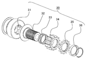
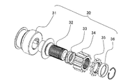
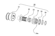
- FIG. 3 is an exploded view of components of the pinion unit 30 according to the first embodiment of the present invention.
- the pinion unit 30 includes an overrunning clutch 31, a shaft core 32, a coil spring 33, a second pinion gear 34, a first pinion gear 35, and a holding component 36.
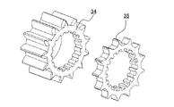
- the pinion gear of the pinion unit 30 is divided into two parts, a second pinion gear 34 and a first pinion gear 35.
- the first pinion gear 35 has a tooth shape for synchronization at the tip, and is a gear for colliding with the ring gear 100, while the second pinion gear 34 is meshed. It is a gear that plays the role of transmitting rotational force later.
- the first pinion gear 35 is configured to have a smaller gear thickness and a smaller moment of inertia than the second pinion gear 34.
- the coil spring 33 is arranged coaxially with the shaft core 32 as shown in FIG.
- the overrunning clutch 31 is coupled to the shaft 20 by a helical spline.
- the shaft core 32 receives the transmission torque from the overrunning clutch 31 and transmits the rotational force to the first pinion gear 35 and the second pinion gear 34 through a groove carved in the shaft core 32.
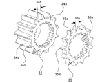
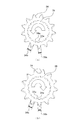
- FIG. 4 is a detailed perspective view of the first pinion gear 35 and the second pinion gear 34 according to the first embodiment of the present invention.
- a first pinion gear groove portion 35a and a second pinion gear groove portion 34a are dug as grooves that can move along the direction of the axis 20, respectively.
- the second pinion gear groove portion 34a is dug as a groove that meshes with the groove of the shaft core 32 with a minimum play.
- the first pinion gear groove portion 35a is dug larger in the width direction and depth direction of the groove than the second pinion gear groove portion 34a.
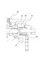
- FIG. 5 is a cross-sectional view of the starter portion at the moment when the first pinion gear 35 and the ring gear 100 collide according to Embodiment 1 of the present invention.
- the pushed pinion part 30 meshes with the ring gear 100 while the first pinion gear 35 of the two divided parts collides with the amount of meshing teeth shifted in the rotational direction.
- FIG. 6 is a diagram showing a positional relationship of the first pinion gear 35 and the second pinion gear 34 according to the first embodiment of the present invention as viewed from the front.
- FIG. 6A shows a state in which the first pinion gear 35 is slightly rotated counterclockwise with respect to the second pinion gear 34.
- FIG. 6B shows a state in which the first pinion gear 35 is slightly rotated to the right with respect to the second pinion gear 34.
- the positional relationship with the two-pinion gear 34 can be either the positional relationship shown in FIGS. 6A and 6B.
- the first pinion gear 35 is rotated by the amount of backlash by the frictional force of the contact portion with respect to the ring gear 100, and searches for the meshing phase.
- the first pinion gear 35 generates the axial force component of the pinion in addition to the processing surface (corresponding to the chamfered portion 35e) and the end surface (corresponding to the tooth surface facing the ring gear 100) of the tooth outer diameter edge portion. It has no surface to generate. That is, as a portion that comes into contact with the ring gear 100, surface contact by an end surface is fundamental, and chamfering is not performed except for the portion of the chamfered portion 35e.
- the first pinion gear 35 comes into contact with the ring gear 100 without being repelled by the impact force due to the rotational speed difference. That is, when the first pinion gear 35 and the ring gear 100 collide, even if the rotational speed difference is large, the pinion gear can be brought into contact without being repelled, there is no repelling meshing loss, and the rotational speed difference is further increased. Even when it is large, the meshing operation can be performed. Furthermore, the ring gear and the pinion gear can be synchronized by the tooth surface collision.
- the tooth thickness 35b of the first pinion gear 35 is smaller than the tooth thickness 34b of the second pinion gear 34. For this reason, the first pinion gear 35 has a large gap with the ring gear 100 and has a shape that can be easily inserted into the ring gear 100, so that the insertability can be improved. Furthermore, since it is possible to avoid applying a torque load when starting the engine with the first pinion gear 35, the first pinion gear 35 can be simplified in weight and size.
- the width of the tooth thickness 35b of the first pinion gear 35 that is rotated by the play of the first pinion gear groove 35a and the shaft core 32 does not exceed the region of the tooth thickness 34b of the second pinion gear 34. With such a tooth thickness, even after the first pinion gear 35 is engaged, the second pinion gear 34 can be smoothly inserted by the action of a chamfered portion 34c and the like described later.
- the first pinion gear 35 when the first pinion gear 35 comes into contact with the ring gear 100, the first pinion gear 35 is related to the phase relationship between the first pinion gear 35 and the ring gear 100. It is also conceivable that is not immediately inserted into the ring gear 100. However, even in such a case, the engine starter according to the first embodiment can perform more reliable synchronization and phase matching instantaneously. This point will be described next with reference to FIGS.
- FIG. 7 is a cross-sectional view of the starter portion in a state where the first pinion gear 35 and the ring gear 100 collide with each other and the first pinion gear 35 is inclined according to the first embodiment of the present invention.
- 8 is a cross-sectional view of the starter portion in a state where the ring gear 100 is inserted into the first pinion gear 35 and abuts against the second pinion gear 34 through the state of FIG. 7 according to the first embodiment of the present invention. is there.
- FIG. 9 shows the starter portion in which the ring gear 100 is inserted into the first pinion gear 35 and the second pinion gear 34 through the state of FIGS.
- FIG. 9 shows the starter portion in which the ring gear 100 is inserted into the first pinion gear 35 and the second pinion gear 34 through the state of FIGS.
- the first pinion gear groove portion 35a is dug larger in the width direction and depth direction of the groove than the second pinion gear groove portion 34a, and the first pinion gear groove portion. 35a has a backlash in the rotational direction and the radial direction with respect to the shaft core 32. Therefore, even if the first pinion gear 35 is not immediately inserted into the ring gear 100 due to the phase relationship, the groove diameter of the first pinion gear 35 has a backlash in the gear radial direction as well as in the gear rotation direction. Will be doing. Thus, the first pinion gear 35 can be tilted as shown in FIG. 7 by having backlash in the gear radial direction.
- a chamfered portion 35e having a corner R is provided on the tooth tip diameter portion of the first pinion gear 35 that contacts the ring gear 100 (see FIG. 4). Therefore, when the ring gear 100 rotates and enters a phase state in which the first pinion gear 35 can be inserted into the next tooth of the ring gear 100, the friction damper between the second pinion gear 34 and the shaft core 32. As a result, the first pinion gear 35 is inserted as shown in FIG. 8 in an operation in which the inclination is returned while being in contact with the ring gear 100.
- the first pinion gear 35 is in contact with the ring gear 100 due to the friction damper effect of the second pinion gear 34 by providing the groove diameter of the first pinion gear 35 with backlash in the gear radial direction as well as in the gear rotation direction. 35 can perform an operation of searching for a gap in the ring gear 100 and can increase a range in which the first pinion gear 35 can be inserted relative to the gap in the ring gear 100.
- the first pinion gear 35 is inserted into the adjacent tooth of the ring gear 100 by the operation of returning the inclination without being repelled by the ring gear 100, and the rotation can be synchronized by the contact between the tooth surfaces.
- the collision surface when inserted is the tooth surface 35d of the first pinion gear 35 and the ring gear 100, and even when there is a difference in the rotational speed, the collision occurs in the rotational direction, and the rotation is synchronized with the torque.
- the clutch is idled by the overrunning clutch 31 when synchronized by applying the tooth surface of the first pinion gear 35, so that the impact is applied to the first pinion gear 35. Because it is only a mass, the impact is small and the noise is small.
- the pinion portion 30 thus synchronized shifts to a state in which the ring gear 100 and the second pinion gear 34 collide as shown in FIG. 8 by further pressing.
- the chamfered portion 34c shown in FIG. 4 is provided on both sides of the tooth surface edge portion of the second pinion gear 34 on the first pinion gear 35 side. Therefore, the second pinion gear 34 and the ring gear 100 are engaged with each other as shown in FIG.
- the chamfered portion 34c has a component that rebounds in the axial direction, but there is no problem because the pinion portion 30 and the ring gear 100 are synchronized by the first pinion gear 35.
- the ring gear 100 can be smoothly inserted into the second pinion gear 34 regardless of the relative rotation direction of the pinion gear and the ring gear 100.
- the first pinion gear 35 meshes with the ring gear 100 and is synchronized with the second pinion gear 34 meshing with the ring gear 100 to start the engine. Can be made. Then, after the second pinion gear 34 and the ring gear 100 are engaged, torque transmission between the pinion portion 30 and the ring gear 100 is performed only between the tooth surface 34d of the second pinion gear and the ring gear 100. As a result, transmission loss can be suppressed by appropriately designing the second pinion gear 34.
- the gear rattling noise that causes the cranking sound when the engine is started is determined by the gear relationship between the second pinion gear 34 and the ring gear 100. For this reason, there is no problem even if the first pinion gear 35 is a tooth having a small tooth thickness and a large backlash. That is, the specification of the teeth of the first pinion gear 35 increases the backlash with the ring gear 100 by changing the displacement, the tip outer diameter, or the pressure angle with respect to the specification of the teeth of the second pinion gear 34. There is no problem.
- the first pinion gear having the synchronization tooth shape as described above is rotated after meshing with the first pinion gear.
- the pinion gear having a structure divided into two parts for the second pinion gear that plays a role of transmitting force it is possible to engage with each other instantly by the operation of one tooth.
- the insertability between the ring gear and the pinion portion can be improved, the tooth shape can be extended due to wear of the end face, and noise and transmission loss can be suppressed.
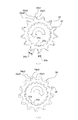
- the first pinion gear is not limited to, for example, a tooth shape as shown in FIG.
- FIG. 10 is a perspective view in which the first pinion gear according to the first embodiment of the present invention is configured with protrusions. As shown in FIG. 10, there is no problem even if the shape of the wave is the same as the number of teeth.
- the mechanism for pushing out the pinion part the case where the pinion part is pushed out by transmitting the pulling force by the plunger to the lever has been described.
- the mechanism is not limited to such a mechanism.
- other power sources such as using motor torque may be used.
- Embodiment 2 the structure of the pinion part that can further suppress wear by decentering the backlash between the first pinion gear 35 and the second pinion gear 34 in the phase will be described.
- the configuration of the engine starting device in the second embodiment is the same as that in FIG. 1 in the first embodiment, and the motor driving force unit 10, the shaft 20, the pinion unit 30, the suction coil unit 40, the plunger 50, and the lever 60.
- the bracket 70, the stopper 80, and the reduction gear unit 90 are configured such that the pinion unit 30 is pushed out while rotating.
- FIG. 11 is an exploded view of the components of the pinion unit 30 according to the second embodiment of the present invention.
- the pinion unit 30 includes an overrunning clutch 31, a shaft core 32, a coil spring 33, a second pinion gear 34, a first pinion gear 35, and a holding component 36.
- the component configuration and role of the pinion gear of the pinion unit 30 are the same as those in the first embodiment, and a detailed description thereof will be omitted.
- FIG. 12 is a detailed perspective view of the first pinion gear 35 and the second pinion gear 34 according to the second embodiment of the present invention.
- a first pinion gear groove portion 35a and a second pinion gear groove portion 34a are dug as grooves that can move along the direction of the axis 20, respectively.
- the second pinion gear groove portion 34a is dug as a groove that meshes with the groove of the shaft core 32 with a minimum play.
- the first pinion gear groove portion 35a is dug larger in the width direction and depth direction of the groove than the second pinion gear groove portion 34a.
- FIG. 13 is a diagram illustrating a positional relationship of the first pinion gear and the second pinion gear according to Embodiment 2 of the present invention as viewed from the front.
- the pinion is eccentric in the surface direction (corresponding to the left rotation direction and the right rotation direction in FIG. 13) in which torque is transmitted to the ring gear 100 by the rotation of the motor. That is, in the first embodiment, as shown in FIG. 6, the amount of the tooth thickness of the second pinion gear 34 protruding from the tooth thickness of the first pinion gear 35 is as shown in FIG. In both cases of 6 (b), the thickness was equivalent. On the other hand, in the second embodiment, the amount of protrusion shown in FIG. 13 (a) is different from the amount of protrusion shown in FIG. 13 (b). "
- FIG. 13A shows a state in which the first pinion gear 35 is displaced in the direction of the arrow due to the pinion rotating in the direction of torque transmission. While torque is being transmitted, the first pinion gear 35 cannot transmit torque on the transmission surface side of the pinion gear because the surface 35d1 of the first pinion gear is more concave than the second pinion gear surface 34d1. Become.
- FIG. 13B shows a state where the rotation speed of the ring gear 100 is fast and the play of the first pinion gear 35 is shifted in the direction of the arrow.
- This state is a state that occurs only when the second pinion gear 34 is not engaged with the ring gear 100 and only the first pinion gear 35 is engaged.
- the state until the first pinion gear 35 meshes with and synchronizes with the ring gear 100 is the same as that of the first embodiment. In this state, the influence of the meshing property due to the eccentricity is irrelevant.
- the pinion gear meshed with and synchronized with the first pinion gear 35 is brought into the state shown in FIG. 8 in the first embodiment by further pressing, and shifts to a state in which the ring gear 100 and the second pinion gear 34 collide. . That is, it is conceivable that the second pinion gear 34 collides with the ring gear 100 in the state as shown in FIG.
- two chamfers of a motor torque transmission surface side chamfer 34c1 and a motor torque non-transmission surface side chamfer 34c2 are applied to the tooth surface edge portion of the second pinion gear 34 on the first pinion gear 35 side. (See FIG. 12).
- the step to the torque transmission surface side of the second pinion gear 34 is small due to the eccentricity, and the ring gear 100 On the other hand, the second pinion gear 34 is easy to enter.
- the chamfer 34c2 on the opposite side to the tooth chamfer 34c1 on the torque transmission surface side by the pinion is different. Further, the size is determined by an area hidden by the backlash of the first pinion gear 35.
- the ring gear 100 is synchronized with the first pinion gear 35 at the moment of contact with the second pinion gear 34, and is in a state where the phase is different. Therefore, by setting the chamfer 34c1 on the torque transmission surface side of the second pinion gear 34 to be an involute chamfer, it is possible to make the chamfer along the rotation of the pinion and to further suppress wear.
- the backlash between the first pinion gear and the second pinion gear is provided so as to be eccentric in phase.
- the phase alignment between the second pinion gear and the first pinion gear is pushed in, the second pinion gear is pushed in smoothly, and problems such as wear are eliminated. Therefore, in the meshing between the ring gear and each of the first pinion gear and the second pinion gear, it is possible to mesh smoothly even when there is a rotational speed difference. As a result, not only can control restrictions be relaxed, restartability can be reduced, noise can be reduced, but wear can be minimized.
- Embodiment 3 In the third embodiment, with respect to the axial movement mechanism of the first pinion gear 35 and the second pinion gear 34, the frictional force of the first pinion gear 35 is provided separately from the shaft core, thereby increasing the damper effect. A structure that can be performed will be described.
- the configuration of the engine starting device in the third embodiment is the same as that in FIG. 1 in the first embodiment, and the motor driving force unit 10, the shaft 20, the pinion unit 30, the suction coil unit 40, the plunger 50, and the lever 60.
- the bracket 70, the stopper 80, and the reduction gear unit 90 are configured such that the pinion unit 30 is pushed out while rotating.
- FIG. 14 is an exploded view of components of the pinion unit 30 according to the third embodiment of the present invention.
- the pinion unit 30 includes an overrunning clutch 31, a shaft core 32, a coil spring 33, a second pinion gear 34, a first pinion gear 35, and a holding component 36.
- the basic component configuration and role of the pinion unit 30 are the same as those in the first embodiment, and a detailed description thereof will be omitted.
- the second pinion gear 34 has a protrusion (hereinafter referred to as a groove protrusion 34e) in which a groove is carved between the groove of the shaft core 32 and the tooth surface of the second pinion 34 in the direction of the first pinion gear 35.
- the first pinion gear 35 is a groove carved in the groove protrusion 34e and meshes with the groove portion 35a of the first pinion gear.
- the groove portion 35a of the first pinion gear and the groove portion 34a of the second pinion gear mesh with separate grooves. Therefore, since the groove portion 35a of the first pinion gear is a groove that does not transmit torque, the number of grooves can be set by reducing the number of teeth, and the meshing shape of the groove protrusion 34e of the second pinion gear is It can be created in a shape that does not depend on the groove shape of the core 32.
- the frictional force of the first pinion gear can be provided separately from the shaft core with respect to the axial movement mechanism of the first pinion gear and the second pinion gear. That is, the first pinion gear can be configured to move in the axial direction independently of the pinion portion. As a result, only the portion of the first pinion gear 35 can be enlarged with respect to the damper function by the frictional force that moves in the axial direction by the spring.
- Embodiment 4 FIG.
- the structure that increases the damper effect has been described with respect to the axial movement mechanism of the first pinion gear 35 and the second pinion gear 34.
- the fourth embodiment when the friction coefficient between the pinion gears 34 and 35 and the ring gear 100 is small with respect to the operation mechanism in the rotational direction of the first pinion gear 35 and the second pinion gear 34, A structure in which the frictional force in the rotational direction of the first pinion gear 35 and the ring gear 100 can be made larger than the frictional force in the rotational direction of the first pinion gear 35 and the second pinion gear 34 will be described.
- the configuration of the engine starting device in the fourth embodiment is the same as that in FIG. 1 in the first embodiment, and the motor driving force unit 10, the shaft 20, the pinion unit 30, the suction coil unit 40, the plunger 50, and the lever 60.
- the bracket 70, the stopper 80, and the reduction gear unit 90 are configured such that the pinion unit 30 is pushed out while rotating.
- FIG. 15 is an exploded view of the components of the pinion unit 30 according to the fourth embodiment of the present invention.
- the pinion unit 30 includes an overrunning clutch 31, a shaft core 32, a coil spring 33, a coil spring 33 b, a second pinion gear 34, a first pinion gear 35, and a holding component 36.
- the basic component configuration and role of the pinion unit 30 are the same as those in the first embodiment, and a detailed description thereof will be omitted.
- the fourth embodiment of the present invention is different in that the coil spring is divided into two (coil springs 33, 33b). Therefore, this difference will be mainly described below.
- FIG. 16 is a cross-sectional view of the starter portion before the first pinion gear 35 and the ring gear 100 collide according to the fourth embodiment of the present invention.
- a coil spring 33 b exists between the first pinion gear 35 and the second pinion gear 34 separately from the coil spring 33 that pushes the second pinion gear 34 in the direction in which the shaft is pushed.
- FIG. 17 is a cross-sectional view of the starter portion in a state where the first pinion gear 35 and the ring gear 100 collide with each other and the first pinion gear 35 is inclined according to the fourth embodiment of the present invention.
- the first pinion gear is separated from the coil spring that pushes the second pinion gear in the pushing direction of the shaft.
- a coil spring is also provided between the pinion gear and the second pinion gear, and the structure of the coil spring divided into two is provided.
Landscapes
- Engineering & Computer Science (AREA)
- Chemical & Material Sciences (AREA)
- Combustion & Propulsion (AREA)
- Mechanical Engineering (AREA)
- General Engineering & Computer Science (AREA)
- Gears, Cams (AREA)
Abstract
リングギア回転中にピニオンギアをリングギアと噛み合わせる場合においても、より確実な同期と位相合わせを当接した瞬時に行う。スタータモータと、出力軸上を軸方向に摺動するピニオン部(30)と、押し出し機構(60)により押し出されたピニオンと噛み合い、スタータモータの回転力が伝達されることでエンジンを始動するリングギア(100)とを備え、ピニオン部(30)は、同期用の歯形状を有し、リングギアとの噛み合い開始時にリングギアと最初に衝突する第1ピニオンギア(35)と、噛み合い後に回転力を伝達する役目を果たす第2ピニオンギア(34)とに、軸方向で2分割されたピニオンギアを有する。
Description
本発明は、エンジン始動時のスタータにおけるピニオンギアと、エンジンのリングギアとの噛み合い性の改善に関するものである。
従来のエンジン始動装置(以降スタータと称す)では、エンジンが停止している状態で、始動動作を行う。したがって、ピニオンギアは、リングギアが回転していない状態で、リングギアとの噛み合わせが行われていた。しかしながら、低燃費化のためにアイドリングストップを行うシステムにおいては、リングギア回転中にもピニオンギアをリングギアと噛み合わせることで、再始動性を確保している。
例えば、アイドリングストップした瞬間でエンジン回転がまだ止まっていない状態で再始動要求が入った場合、あるいは停止状態から再始動の際に時間を短縮する必要がある場合には、リングギアの回転中に事前にピニオンギアとの噛み合わせを実施している。
このような場合に、リングギアの回転中にピニオンギアを噛み合わせる方法としては、リングギアの回転数に同期させるようにピニオンギアのスタータモータを調速通電して噛み合わせる方法がある(例えば、特許文献1参照)。また、事前に同期するための機構を設けることで、その機構部の摩擦により一定の回転数差まで同期させてからギアを噛み合わせる方法がある(例えば、特許文献2参照)。さらに、ピニオン形状を工夫することで、噛み合いやすくする方法などもある(例えば、特許文献3参照)。
しかしながら、従来技術には、以下のような課題がある。
リングギアは、エンジン停止後に惰性回転で減速するが、この場合、ピストンの圧縮膨張によるトルクの変動で回転数が脈動しながら停止する。したがって、例えば、特許文献1のように、エンジン始動装置(スタータ)にてリングギアとピニオンギアとの回転数を同期させて、これらを噛み合わせるためには、複雑な構成が必要となる。具体的には、リングギアとピニオンギアの回転数を取得または予測して、これらに基づき、スタータを制御して噛み合わせる複雑な構成が必要となる。
リングギアは、エンジン停止後に惰性回転で減速するが、この場合、ピストンの圧縮膨張によるトルクの変動で回転数が脈動しながら停止する。したがって、例えば、特許文献1のように、エンジン始動装置(スタータ)にてリングギアとピニオンギアとの回転数を同期させて、これらを噛み合わせるためには、複雑な構成が必要となる。具体的には、リングギアとピニオンギアの回転数を取得または予測して、これらに基づき、スタータを制御して噛み合わせる複雑な構成が必要となる。
また、同期させるだけでなく、ピニオンギアとリングギアの位相を一致させなければ噛み合わない。このため、同期させたそれぞれのギアに対して、正確な回転方向の位置を認識する必要がある.しかしながら、このような高精度な制御を行うためには、高精度なエンコーダなどの検出器や、エンジン側ECUの高速演算処理が必要になる。また、エンコーダなどによるピニオンギアの位相の検出は、ピニオンギア自体が移動体であるため、取り付けることが困難であり、システムも複雑になるとともに、装置も大型化する。
さらに、それぞれの回転を予測してピニオンを飛び込ませる方法で簡易化することで、複雑な構成を実現化した場合でも、予測値の誤差と、ピニオンを軸方向に飛び込ませるタイミングのばらつきによって、当接時の回転数差が発生するため、正確な制御は困難である。
一方、例えば、特許文献2のように、ピニオンギアとリングギアを事前にシンクロ機構によって回転数を合わせて当接させる構成とすることで、より簡素な構成でリングギアとピニオンギアとの回転数を同期させることができる。しかしながら、ピニオンギアとリングギアは、通常、モータの小型化のためにもギア比が10倍レベルで存在し、寸法構成上の制約から同軸上でない。したがって、ピニオンギアからリングギアへ当接させるシンクロ機構の摩擦面は、常にすべりが生じながらの同期となり、位相まで一致した完全な同期を実現することは困難である。
また、シンクロ機構において、同期した後にリングギアとピニオンギアが当接した時点では、その時点で偶然位相が一致している場合を除いて、リングギアとピニオンギアとの間ですべりが生じ、位相が一致した時点で噛み合うこととなる。このように、シンクロ機構を用いる構成においては、すべりによって同期させてからピニオンとリングギアを当接させることとなる。このため、その際の騒音や磨耗の問題、または別途同期させる磨耗面が必要となることから別途の空間が必要となるという問題があった。
また、例えば、シンクロ機構を用いる場合において、特許文献3のように、ピニオンギアとリングギアが噛み合いやすくするために、ピニオンの先端の形状を工夫して、歯先端に面取りなどを設けることが考えられる。これにより、特許文献3では、面取りによる空間分の挿入が可能になるとともに、面当りによる誘い効果を実施している。
ここで、リングギアが停止している状態での噛み合わせであれば、面取りによる誘い効果はある。しかしながら、リングギア回転中においてピニオンの相対回転数が異なる場合には、面取り部の当接によって両ギアが衝突することで、ピニオンを軸方向に押し戻す力成分が発生する。これにより、噛み合わせ時に衝突音や噛み合わせの遅れが生じるという問題があった。
このように、リングギア回転中にピニオンギアを噛み合わせる場合、より確実な同期と位相合わせを、当接した瞬時に行わないと、騒音、磨耗による寿命の低下、そして噛み合い時間のロスによる始動の遅れなどが生じることになる。
特に、ピニオンギアとリングギアが噛み合わせ時に回転数差が大きい場合には、歯と歯がこすれあって騒音を出しながら噛み合いを行うこととなる。この結果、歯の磨耗などによる寿命の問題とともに、面取り面などで回転数差のトルク力が軸方向の力となり大きくピニオンギアが弾き飛ばされて、噛み合い時間にロスが発生して再始動性も悪くなるといった問題があった。
本発明は、このような問題を解決するためになされたもので、リングギア回転中にピニオンギアをリングギアと噛み合わせる場合においても、より確実な同期と位相合わせを当接した瞬時に行い、騒音、磨耗による寿命の低下、および噛み合い時間のロスによる始動性の遅れを抑制するエンジン始動装置を得ることを目的とする。
本発明に係るエンジン始動装置は、スタータモータと、スタータモータの出力軸側にスプライン結合された軸方向に摺動するピニオン部と、ピニオン部をリングギアとの噛み合い位置に移動させる押し出し機構を有し、押し出し機構により押し出されたピニオンと噛み合い、スタータモータの回転力が伝達されることでエンジンを始動するリングギアとを備えたエンジン始動装置において、ピニオン部は、同期用の突起状を有し、リングギアとの噛み合い開始時にリングギアと最初に衝突する第1ピニオンギアと、噛み合い後に回転力を伝達する役目を果たす第2ピニオンギアとに、軸方向で2分割されたピニオンギアを有するものである。
本発明によれば、ピニオン部のピニオンギアを、同期用の歯形状を先端に有する第1ピニオンギアと、噛み合い後に回転力を伝達する役目を果たす第2ピニオンギアに分割した構成とすることで、回転数差がある場合にも安定してピニオンとリングギアとを噛み合わせることが可能であり、リングギア回転中にピニオンギアを噛み合わせる場合においても、より確実な同期と位相合わせを当接した瞬時に行い、騒音、磨耗による寿命の低下、および噛み合い時間の時間のロスによる始動性の遅れが生じないエンジン始動装置を得ることができる。
以下、本発明のエンジン始動装置の好適な実施の形態につき図面を用いて説明する。
実施の形態1.
図1は、本発明の実施の形態1におけるエンジン始動装置の分解図である。図1に示す本実施の形態1におけるエンジン始動装置は、モータ駆動力部10、軸20、ピニオン部30、吸引コイル部40、プランジャ50、レバー60、ブラケット70、ストッパ80および減速ギア部90で構成されている。
図1は、本発明の実施の形態1におけるエンジン始動装置の分解図である。図1に示す本実施の形態1におけるエンジン始動装置は、モータ駆動力部10、軸20、ピニオン部30、吸引コイル部40、プランジャ50、レバー60、ブラケット70、ストッパ80および減速ギア部90で構成されている。
モータ駆動力部10は、エンジンを始動する。軸20は、モータの出力軸側と減速ギア部90を介して結合している。ピニオン部30は、軸20とヘリカルスプライン結合されたオーバーランニングクラッチと一体化されており、軸方向に摺動することができる。
吸引コイル部40は、スイッチをONすることで、プランジャ50を吸引する。レバー60は、吸引によるプランジャ50の移動を、ピニオン部30に伝達する。ブラケット70は、モータ駆動力部10、軸20、およびピニオン部30からなるそれぞれの部品を、ピニオンが移動した際のストッパ80を介してエンジン側に固定している。
図2は、本発明の実施の形態1におけるエンジン始動装置をエンジンに取り付けた際の断面図である。エンジン始動を行う場合は、スイッチがONされると、リレー接点が閉じ、吸引コイル部40の吸引コイル41に電流が流れて、プランジャ50が吸引される。プランジャ50が吸引されると、レバー60が引き込まれて、レバー60がレバー回転軸中心61を中心として回転する。
回転したレバー60において、プランジャ50とは反対側の端部が、ピニオン部30を押し出し、その結果、軸20のスプラインに沿って、ピニオン部30が回転しながら押し出される。
図3は、本発明の実施の形態1におけるピニオン部30の構成部品の分解図である。ピニオン部30は、オーバーランニングクラッチ31、軸芯32、コイルバネ33、第2ピニオンギア34、第1ピニオンギア35、および保持部品36を備えて構成されている。
ここで、ピニオン部30のピニオンギアは、第2ピニオンギア34および第1ピニオンギア35の2つに分割されている。そして、詳細は後述するが、第1ピニオンギア35は、同期用の歯形状を先端に有しており、リングギア100と衝突するためのギアであり、一方、第2ピニオンギア34は、噛み合い後に回転力を伝達する役目を果たすギアである。また、第1ピニオンギア35は、第2ピニオンギア34よりギア厚さが薄く、慣性モーメントが小さく構成されている。
コイルバネ33は、図3に示すように、軸芯32と同軸上に配置されている。また、オーバーランニングクラッチ31は、軸20とヘリカルスプライン結合されている。軸芯32は、オーバーランニングクラッチ31からの伝達トルクを受けて、軸芯32に彫られている溝で第1ピニオンギア35、第2ピニオンギア34へ回転力を伝える。
図4は、本発明の実施の形態1による第1ピニオンギア35と第2ピニオンギア34の詳細斜視図である。第1ピニオンギア35および第2ピニオンギア34には、軸20方向に沿って移動できる溝として、それぞれ第1ピニオンギア溝部35aおよび第2ピニオンギア溝部34aが掘られている。
ここで、第2ピニオンギア溝部34aは、軸芯32の溝とガタを最小限にして噛み合う溝として掘られている。一方、第1ピニオンギア溝部35aは、第2ピニオンギア溝部34aよりも、溝の幅方向および深さ方向に大きく掘られている。この結果、第1ピニオンギア溝部35aは、軸芯32に対してガタをもつため、回転方向にこのガタ分だけ回転できる構造となっている。
図5は、本発明の実施の形態1による第1ピニオンギア35とリングギア100が衝突した瞬間のスタータ部の断面図である。押し出されたピニオン部30は、まず始めに、2分割されたうちの第1ピニオンギア35が、噛み合いの歯が回転方向にずれている分を衝突させながら、リングギア100と噛み合うこととなる。
また、図6は、本発明の実施の形態1による第1ピニオンギア35と第2ピニオンギア34の正面からみた位置関係を示す図である。図6(a)は、第2ピニオンギア34に対して、第1ピニオンギア35が若干左回転した位置にある状態を示している。また、図6(b)は、第2ピニオンギア34に対して、第1ピニオンギア35が若干右回転した位置にある状態を示している。
先の図5に示したように、第1ピニオンギア35がリングギア100に当接した際には、リングギア100との当接面の回転方向の摩擦力で、第1ピニオンギア35と第2ピニオンギア34との位置関係は、このような図6(a)、図6(b)のどちらの位置関係にもなり得る。
すなわち、第1ピニオンギア35は、リングギア100に対して接触部の摩擦力によってガタの寸法分だけ回転により移動し、噛み合いの位相を探る動作をする。特に、第1ピニオンギア35は、歯先外径エッジ部の処理面(面取り部35eに相当)および端面(リングギア100に対向する歯面に相当)以外に、ピニオンの軸方向の力成分を生じさせる面をもっていない。すなわち、リングギア100と当接する部分としては、端面による面接触が基本となり、面取り部35eの部分以外には面取りが成されていない。
この結果、第1ピニオンギア35は、回転数差による衝撃力ではじかれることなく、リングギア100と当接する。すなわち、第1ピニオンギア35とリングギア100が衝突した際に、回転数差が大きくても、ピニオンギアがはじかれることなく当接することができ、はじかれる噛み合いロスがなくなり、より回転数差が大きい場合にも、噛み合い動作を実施することが可能となる。さらに、歯面の衝突によって、リングギアとピニオンギアを同期させることができる。
そして、第1ピニオンギア35の歯厚35bは、第2ピニオンギア34の歯厚34bよりも小さい形状としている。このため、第1ピニオンギア35は、リングギア100との隙間が大きくなっており、リングギア100に挿入しやすい形状になっており、挿入性を改善できる。さらに、第1ピニオンギア35でのエンジン立ち上げ時のトルク負荷が加わることを避けることができるため、第1ピニオンギア35の軽量化や小型化などの簡易化が可能となる。
なお、第1ピニオンギア溝部35aと軸芯32のガタによって回転する第1ピニオンギア35の歯厚35bの幅は、第2ピニオンギア34の歯厚34bの領域を超えないものとする。このような歯厚とすることで、第1ピニオンギア35を噛み合わせた後も、後述する面取り部34cなどの働きで、第2ピニオンギア34を円滑に挿入完了することができる。
また、先の図5に示したように、第1ピニオンギア35がリングギア100に当接した際には、第1ピニオンギア35とリングギア100との位相の関係で、第1ピニオンギア35がリングギア100に対して直ちに挿入されない場合も考えられる。しかしながら、このような場合にも、本実施の形態1におけるエンジン始動装置は、より確実な同期と位相合わせを当接した瞬時に行うことができる。そこで、この点を、図7~図9を用いて、次に説明する。
図7は、本発明の実施の形態1による第1ピニオンギア35とリングギア100が衝突して第1ピニオンギア35が傾いている状態のスタータ部の断面図である。また、図8は、本発明の実施の形態1による図7の状態を経て、第1ピニオンギア35にリングギア100が挿入されて第2ピニオンギア34に当接する状態のスタータ部の断面図である。さらに、図9は、本発明の実施の形態1による図7、図8の状態を経て、第1ピニオンギア35および第2ピニオンギア34にリングギア100が挿入され、噛み合い状態となったスタータ部の断面図である。
図7に示すように、位相の関係で、第1ピニオンギア35がリングギア100に対して直ちに挿入されない場合には、当接時において、第1ピニオンギア35は、リングギア100に押し付けられて傾く。その際には、第2ピニオンギア34を介してコイルバネ33が縮みながら第1ピニオンギア35をリングギア100に押し付けている状態になる。
ここで、先の図4で説明したように、第1ピニオンギア溝部35aは、第2ピニオンギア溝部34aよりも、溝の幅方向および深さ方向に大きく掘られており、第1ピニオンギア溝部35aは、軸芯32に対して、回転方向および径方向にガタを持っている。したがって、位相の関係で、第1ピニオンギア35がリングギア100に対して直ちに挿入されない場合にも、第1ピニオンギア35の溝径には、ギア回転方向とともに、ギア径方向にもガタを有していることとなる。このように、ギア径方向にもガタを有することで、第1ピニオンギア35は、図7に示したように傾くことができる。
さらに、リングギア100と当接する第1ピニオンギア35の歯先径部には、角Rの面取り部35eが設けられている(図4参照)。そこで、リングギア100が回転して、リングギア100の次の歯に対して第1ピニオンギア35が挿入可能な位相状態となった際に、第2ピニオンギア34と軸芯32との摩擦ダンパー効果で、第1ピニオンギア35は、リングギア100に当接したままで傾きが戻るような動作で、先の図8のように挿入されることとなる。
すなわち、第1ピニオンギア35の溝径に、ギア回転方向とともに、ギア径方向にもガタを持たせることで、第2ピニオンギア34の摩擦ダンパー効果によりリングギア100と当接した第1ピニオンギア35は、リングギア100の隙間を探す動作を行うことができるとともに、リングギア100の隙間に対して相対的に第1ピニオンギア35の挿入できる範囲を増加させることができる。
この結果、第1ピニオンギア35は、リングギア100にはじかれることなく、傾きが戻ろうとする動作によってリングギア100の隣接歯に挿入され、歯面同士の当たりにより回転を同期させることができる。
挿入された際の衝突面は、第1ピニオンギア35の歯面35dとリングギア100であり、回転数差があった場合にも回転方向の衝突となるため、そのトルクで回転が同期する。特に、リングギア100の回転数が早い場合には、第1ピニオンギア35の歯面を当てることによって同期させると、オーバーランニングクラッチ31によりクラッチが空回りするため、その衝撃は、第1ピニオンギア35のみの質量となるため、衝撃も小さく騒音も小さい。
このようにして同期したピニオン部30は、さらなる押し込みによって、先の図8に示すように、リングギア100と第2ピニオンギア34とが衝突する状態に移行する。ここで、第2ピニオンギア34の第1ピニオンギア35側の歯面エッジ部両側には、先の図4に示す面取り部34cが設けられている。したがって、この面取り部34cに誘われて、第2ピニオンギア34とリングギア100が、図9のように噛み合う結果となる。
この際に、面取り部34cは、軸方向に跳ね返す成分をもっているが、ピニオン部30とリングギア100とは、第1ピニオンギア35により同期しているため、問題ない。また、面取り部34cを有することにより、ピニオンギアとリングギア100の相対回転方向がどちらの場合にも、第2ピニオンギア34へリングギア100を円滑に挿入完了することができる。
したがって、図7~図9に示した一連の動作が行われることで、第1ピニオンギア35がリングギア100と噛みあって同期した後に、第2ピニオンギア34がリングギア100と噛み合いエンジンを始動させることができる。そして、第2ピニオンギア34とリングギア100が噛み合った後は、ピニオン部30とリングギア100とのトルク伝達は、第2ピニオンギアの歯面34dとリングギア100間でのみ行われる。この結果、第2ピニオンギア34を適切に設計することで、伝達損失を抑制することができる。
したがって、第2ピニオンギア34とリングギア100とのギア関係で、エンジン始動時のクランキング音の原因となる歯打ち音などは決定される。このため、第1ピニオンギア35は、歯厚を小さくしたバックラッシが大きい歯としても問題はない。すなわち、第1ピニオンギア35の歯の仕様は、第2ピニオンギア34の歯の仕様に対して、転位、歯先外径、もしくは圧力角を変えることで、リングギア100とのバックラッシを大きくしても問題ない。
以上のように、実施の形態1によれば、リングギアとピニオン部との回転数差がある場合でも、上述したような同期用の歯形状を先端に有する第1ピニオンギアと、噛み合い後に回転力を伝達する役目を果たす第2ピニオンギアとに2分割された構成を有するピニオンギアを用いることで、歯一つ分の動作で瞬時に噛み合いが可能となる。この結果、リングギアとピニオン部との挿入性を改善でき、端面の磨耗による歯形状の長寿命化を図ることができ、さらに、騒音の抑制、および伝達損失の抑制も可能となる。
例えば、リングギアの回転数がピニオンギアよりも500rpm速い場合にも、ピニオンギアが弾かれることなく瞬時に噛み合い、噛み合い瞬間の騒音レベルも5dBレベルで低くなることが検証できた。したがって、本願の構成を備えたピニオン部を用いて、アイドリング回転数レベルにおいて飛び込み動作を実施することで、安定してピニオンとリングギアとを噛み合わせることが可能となり、制御の制限の緩和、再始動性の時間の短縮が可能となる。
ここで、第1ピニオンギアは、例えば、先の図4に示したような、歯の形状をしている場合に限定されるものではない。図10は、本発明の実施の形態1による第1ピニオンギアが突起で構成されている斜視図である。この図10に示すように、波の形状で、歯の数と同じ突起形状としても問題ない。
また、ピニオン部を押し出す機構に関しては、プランジャによる引き込み力をレバーに伝達させることでピニオン部を押し出す場合について説明したが、このような機構に限定されるものではない。ピニオン部を押し出す方法として、モータトルクを使用するなどの他の動力源を使用しても構わない。
実施の形態2.
本実施の形態2では、第1ピニオンギア35と第2ピニオンギア34とのガタに関して、位相において偏心させることで、磨耗をさらに抑制できるピニオン部の構造について説明する。
本実施の形態2では、第1ピニオンギア35と第2ピニオンギア34とのガタに関して、位相において偏心させることで、磨耗をさらに抑制できるピニオン部の構造について説明する。
本実施の形態2におけるエンジン始動装置の構成は、先の実施の形態1における図1と同様であり、モータ駆動力部10、軸20、ピニオン部30、吸引コイル部40、プランジャ50、レバー60、ブラケット70、ストッパ80および減速ギア部90で構成されており、ピニオン部30が回転しながら押し出される。
図11は、本発明の実施の形態2におけるピニオン部30の構成部品の分解図である。ピニオン部30は、オーバーランニングクラッチ31、軸芯32、コイルバネ33、第2ピニオンギア34、第1ピニオンギア35、および保持部品36を備えて構成されている。ここで、ピニオン部30のピニオンギアの部品構成と役目は、先の実施の形態1と同様であり、詳細な説明は省略する。
図12は、本発明の実施の形態2による第1ピニオンギア35と第2ピニオンギア34の詳細斜視図である。第1ピニオンギア35および第2ピニオンギア34には、軸20方向に沿って移動できる溝として、それぞれ第1ピニオンギア溝部35aおよび第2ピニオンギア溝部34aが掘られている。
ここで、第2ピニオンギア溝部34aは、軸芯32の溝とガタを最小限にして噛み合う溝として掘られている。一方、第1ピニオンギア溝部35aは、第2ピニオンギア溝部34aよりも、溝の幅方向および深さ方向に大きく掘られている。この結果、第1ピニオンギア溝部35aは、軸芯32に対してガタをもつため、回転方向にこのガタ分だけ回転できる構造となっている。
ここで、本実施の形態2におけるガタは、第1ピニオンギア35と第2ピニオンギア34の関係において、位相において偏心している。そこで、この偏心について、図面を用いて説明する。図13は、本発明の実施の形態2による第1ピニオンギアと第2ピニオンギアの正面からみた位置関係を示す図である。
モータの回転によってピニオンがリングギア100にトルクを伝達する面方向(図13における左回転方向、右回転方向に相当)に偏心させている。すなわち、先の実施の形態1では、図6に示すように、第1ピニオンギア35の歯厚に対して第2ピニオンギア34の歯厚がはみ出している量は、図6(a)と図6(b)のどちらの場合も同等の厚みであった。これに対して、本実施の形態2では、図13(a)に示したはみ出し量と図13(b)に示したはみ出し量が異なっており、このことを「トルクを伝達する面方向に偏心させている」と表現している。
そこで、図13(a)、図13(b)に関して、以下に詳述する。図13(a)は、ピニオンがトルク伝達する方向へ回転して、矢印の方向へ第1ピニオンギア35がガタによりずれた状態を示している。トルク伝達している間において、ピニオンギアの伝達面側は、第1ピニオンギアの面35d1が第2ピニオンギア面34d1よりも凹になっているため、第1ピニオンギア35ではトルク伝達できない状態となる。
また、図13(b)は、リングギア100の回転速度が速く、第1ピニオンギア35のガタが矢印の方向にずれている状態を示している。この状態は、まだ第2ピニオンギア34がリングギア100とは噛み合っておらず、第1ピニオンギア35のみが噛み合っているときしか起こらない状態である。
第1ピニオンギア35がリングギア100と噛み合い同期するまでの状態は、先の実施の形態1と同様である。そして、この状態においては、この偏心による噛み合い性の影響は、無関係である。
その後、第1ピニオンギア35が噛み合い同期したピニオンギアは、さらなる押し込みによって、先の実施の形態1における図8の状態になり、リングギア100と第2ピニオンギア34とが衝突する状態に移行する。すなわち、図13(a)あるいは図13(b)のような状態で、第2ピニオンギア34がリングギア100と衝突することが考えられる。
ここで、第2ピニオンギア34の第1ピニオンギア35側の歯面エッジ部には、モータトルク伝達面側面取り部34c1とモータトルク非伝達面側面取り部34c2の2つの面取りが施されている(図12参照)。そして、図13(a)の状態で、リングギア100が面取り34c1に衝突する際には、偏心していることで、第2ピニオンギア34のトルク伝達面側への段差は小さく、リングギア100に対して第2ピニオンギア34が入りやすくなっている。
一方、図13(b)の状態で、トルク伝達面の反対側のエッジ部の面取り34c2がリングギア100と衝突する場合には、ワンウェイクラッチによりピニオンが空回りすることで、面をこする力が小さいため、段差が大きくても問題にならない。すなわち、偏心させることによって、ピニオン側面取り部とリングギア100との衝突によるこすれる力が大きくなる側の面の段差を小さくすることで、磨耗を最小限にすることが可能となる。
したがって、本実施の形態2のように、第1ピニオンギア35と第2ピニオンギア34とを偏心させている場合には、ピニオンによるトルク伝達面側の歯面の面取り34c1と反対側の面取り34c2の大きさは異なる。さらに、その大きさは、第1ピニオンギア35のガタによって隠れる領域で決定される。
さらに、リングギア100は、第2ピニオンギア34に当接する瞬間には、第1ピニオンギア35と同期しており、位相が異なっている状態である。したがって、第2ピニオンギア34のトルク伝達面側の面取り34c1をインボリュート面取りにすることで、ピニオンの回転に沿った面取りとすることができ、磨耗をさらに抑制できる。
以上のように、実施の形態2によれば、第1ピニオンギアと第2ピニオンギアとのガタを、位相において偏心するように設けている。この結果、第2ピニオンギアと第1ピニオンギアとの位相合わせの押し込みにおいて、第2ピニオンギアが円滑に押し込まれることとなり、磨耗などの問題もなくなる。したがって、リングギアと、第1ピニオンギア、第2ピニオンギアのそれぞれとの噛み合いにおいて、回転数差が存在した際にも円滑に噛み合うことが可能となる。この結果、制御の制限の緩和、再始動性の時間の短縮と騒音の低減だけでなく、磨耗も最小限にできる。
実施の形態3.
本実施の形態3では、第1ピニオンギア35と第2ピニオンギア34との軸方向の動作機構に関して、第1ピニオンギア35の摩擦力を軸芯と別部で設けることで、ダンパー効果を大きくすることができる構造について説明する。
本実施の形態3では、第1ピニオンギア35と第2ピニオンギア34との軸方向の動作機構に関して、第1ピニオンギア35の摩擦力を軸芯と別部で設けることで、ダンパー効果を大きくすることができる構造について説明する。
本実施の形態3におけるエンジン始動装置の構成は、先の実施の形態1における図1と同様であり、モータ駆動力部10、軸20、ピニオン部30、吸引コイル部40、プランジャ50、レバー60、ブラケット70、ストッパ80および減速ギア部90で構成されており、ピニオン部30が回転しながら押し出される。
図14は、本発明の実施の形態3におけるピニオン部30の構成部品の分解図である。ピニオン部30は、オーバーランニングクラッチ31、軸芯32、コイルバネ33、第2ピニオンギア34、第1ピニオンギア35、および保持部品36を備えて構成されている。ここで、ピニオン部30の基本的な部品構成と役目は、先の実施の形態1と同様であり、詳細な説明は省略する。
先の実施の形態1と比較すると、本発明の実施の形態3では、第1ピニオンギア35、第2ピニオンギア34、および軸心32の形状が異なる。そこで、これらの相違点を中心に、以下に説明する。第2ピニオンギア34は、第1ピニオンギア35方向に、軸芯32の溝と第2ピニオン34の歯面との間で溝が彫られた突起(以下、溝突起34eと称す)を有している。第1ピニオンギア35は、この溝突起34eに彫られた溝で、第1ピニオンギアの溝部35aと噛み合っている。
本実施の形態3においては、第1ピニオンギアの溝部35aと第2ピニオンギアの溝部34aとは、別々の溝に噛み合う。このため、第1ピニオンギアの溝部35aは、トルク伝達を行わない溝であるから、歯数を小さくして溝数の数を設定でき、第2ピニオンギアの溝突起34eの噛み合い形状は、軸芯32の溝形状に依存しない形状で作成することが可能となる。
なお、第1ピニオンギア35と第2ピニオンギア34の軸方向の摩擦力と、コイルバネ33が最大ストロークまで縮むことができる荷重との合計が、ピニオンを押し出す荷重を上回らないようにすることが必要である。
以上のように、実施の形態3によれば、第1ピニオンギアと第2ピニオンギアとの軸方向の動作機構に関して、第1ピニオンギアの摩擦力を軸芯と別部で設けることができる。すなわち、第1ピニオンギアは、ピニオン部に対して独立して軸方向に移動できる構成とすることができる。この結果、バネによって軸方向に移動する、摩擦力によるダンパー機能について、第1ピニオンギア35の部分のみを大きくすることが可能となる。
実施の形態4.
先の実施の形態3では、第1ピニオンギア35と第2ピニオンギア34との軸方向の動作機構に関して、ダンパー効果を大きくする構造について説明した。これに対して、本実施の形態4では、第1ピニオンギア35と第2ピニオンギア34との回転方向の動作機構に関して、ピニオンギア34、35とリングギア100の摩擦係数が小さい場合に、第1ピニオンギア35とリングギア100の回転方向の摩擦力を、第1ピニオンギア35と第2ピニオンギア34の回転方向の摩擦力よりも大きくすることができる構造について説明する。
先の実施の形態3では、第1ピニオンギア35と第2ピニオンギア34との軸方向の動作機構に関して、ダンパー効果を大きくする構造について説明した。これに対して、本実施の形態4では、第1ピニオンギア35と第2ピニオンギア34との回転方向の動作機構に関して、ピニオンギア34、35とリングギア100の摩擦係数が小さい場合に、第1ピニオンギア35とリングギア100の回転方向の摩擦力を、第1ピニオンギア35と第2ピニオンギア34の回転方向の摩擦力よりも大きくすることができる構造について説明する。
本実施の形態4におけるエンジン始動装置の構成は、先の実施の形態1における図1と同様であり、モータ駆動力部10、軸20、ピニオン部30、吸引コイル部40、プランジャ50、レバー60、ブラケット70、ストッパ80および減速ギア部90で構成されており、ピニオン部30が回転しながら押し出される。
図15は、本発明の実施の形態4におけるピニオン部30の構成部品の分解図である。ピニオン部30は、オーバーランニングクラッチ31、軸芯32、コイルバネ33、コイルバネ33b、第2ピニオンギア34、第1ピニオンギア35、および保持部品36を備えて構成されている。ここで、ピニオン部30の基本的な部品構成と役目は、先の実施の形態1と同様であり、詳細な説明は省略する。
先の実施の形態1と比較すると、本発明の実施の形態4では、コイルバネが2分割(コイルバネ33、33b)されている点が異なる。そこで、この相違点を中心に、以下に説明する。
図16は、本発明の実施の形態4による第1ピニオンギア35とリングギア100が衝突する前のスタータ部の断面図である。本実施の形態4では、第2ピニオンギア34を軸の押し込む方向へ押しているコイルバネ33とは別に、第1ピニオンギア35と第2ピニオンギア34との間にコイルバネ33bが存在している。
図17は、本発明の実施の形態4による第1ピニオンギア35とリングギア100が衝突して第1ピニオンギア35が傾いている状態のスタータ部の断面図である。コイルバネ33とコイルバネ33bによる2分割構成とすることで、図17に示すように、第1ピニオンギア35がリングギア100に当接して、コイルバネ33が縮んでいく。
その際に、第1ピニオンギア35と第2ピニオンギア34との間にコイルバネ33bが突っ張っているため、第2ピニオンギア34と第1ピニオンギア35の接触する摩擦力を下げることができる。このとき、コイルバネ33bと第1ピニオンギア35の回転方向の摩擦力は小さくしておく必要がある。これにより、第1ピニオンギア35の回転方向のガタは、第2ピニオンギア34の慣性に関係なく、回転しやすくなり、当接時に同期しやすくなる。
以上のように、実施の形態4によれば、第1ピニオンギアと第2ピニオンギアとの回転方向の動作機構に関して、第2ピニオンギアを軸の押し込む方向へ押しているコイルバネとは別に、第1ピニオンギアと第2ピニオンギアとの間にもコイルバネを設け、2分割されたコイルバネの構成を備えている。この結果、第1ピニオンギアの回転方向のガタは、第2ピニオンギアの慣性に関係なく、回転しやすくなり、当接時に同期しやすくすることができる。
Claims (19)
- スタータモータと、
前記スタータモータの出力軸側にスプライン結合された軸方向に摺動するピニオン部と、
前記ピニオン部をリングギアとの噛み合い位置に移動させる押し出し機構を有し、前記押し出し機構により押し出された前記ピニオン部のピニオンと噛み合い、前記スタータモータの回転力が伝達されることでエンジンを始動するリングギアと
を備えたエンジン始動装置において、
前記ピニオン部は、同期用の突起形状を有し、前記リングギアとの噛み合い開始時に前記リングギアと最初に衝突する第1ピニオンギアと、噛み合い後に回転力を伝達する役目を果たす第2ピニオンギアとに、前記軸方向で2分割されたピニオンギアを有することを特徴とするエンジン始動装置。 - 請求項1に記載のエンジン始動装置において、
前記第1ピニオンギアの前記同期用の突起形状は、前記第2ピニオンギアの歯数と同じ数の突起で構成され、前記突起は、軸方向垂直断面の領域が前記第2ピニオンギアの面領域よりも小さく構成されていることを特徴とするエンジン始動装置。 - 請求項2に記載のエンジン始動装置において、
前記第1ピニオンギアの前記同期用の突起形状は、前記第2ピニオンギアの歯数と同じ数の歯で構成されていることを特徴とするエンジン始動装置。 - 請求項3に記載のエンジン始動装置において、
前記第1ピニオンギアの前記歯の仕様は、前記第2ピニオンギアの転位、歯先外径、もしくは圧力角を変えることで、前記リングギアとのバックラッシを大きくしていることを特徴とするエンジン始動装置 - 請求項2ないし4のいずれか1項に記載のエンジン始動装置において、
前記第1ピニオンギアの前記同期用の突起形状は、前記リングギアの回転方向の衝突に対して前記ピニオン部の軸方向成分の力を生じさせる面を、歯先外径エッジ部の処理面および端面以外に持たないことを特徴とするエンジン始動装置。 - 請求項2ないし4のいずれか1項に記載のエンジン始動装置において、
前記第1ピニオンギアは、前記ピニオン部の軸に対して回転方向のガタを有することを特徴とするエンジン始動装置。 - 請求項6に記載のエンジン始動装置において、
前記第1ピニオンギアの前記回転方向のガタによって動作できる範囲は、前記第2ピニオンギアが前記リングギアと噛み合った後に前記第1ピニオンギアによる回転トルク力が前記リングギアに伝わらない範囲であることを特徴とするエンジン始動装置。 - 請求項7に記載のエンジン始動装置において、
前記第1ピニオンギアの前記回転方向のガタによって動作できる範囲は、前記第2ピニオンギアに対してトルク伝達方向面側へ偏っていることを特徴とするエンジン始動装置。 - 請求項1ないし8のいずれか1項に記載のエンジン始動装置において、
前記第1ピニオンギアは、前記ピニオン部に対して独立して軸方向に移動できる構成を備えることを特徴とするエンジン始動装置。 - 請求項9に記載のエンジン始動装置において、
前記第2ピニオンギアは、前記ピニオン部の軸方向において、バネにて押し出し方向に押さえ付けられて前記第1ピニオンギアを介して前記ピニオン部の軸に位置決めされており、前記バネが縮むことで軸方向に移動できることを特徴とするエンジン始動装置。 - 請求項10に記載のエンジン始動装置において、
前記ピニオン部は、前記第1ピニオンギアと前記第2ピニオンギアとが軸方向に独立して動作可能な構成を備えることを特徴とするエンジン始動装置。 - 請求項11に記載のエンジン始動装置において、
前記第1ピニオンギアは、前記第2ピニオンギアを支えている前記バネを押すことで軸方向に移動できることを特徴とするエンジン始動装置。 - 請求項10なし12のいずれか1項に記載のエンジン始動装置において、
前記第1ピニオンギアと前記第2ピニオンギアの軸方向の摩擦力と、前記バネが最大ストロークまで縮むことができる荷重との合計が、前記ピニオンを押し出す荷重を上回らないことを特徴とするエンジン始動装置。 - 請求項1ないし8のいずれか1項に記載のエンジン始動装置において、
前記第1ピニオンギアと前記第2ピニオンギアとの回転方向の摩擦力が、前記第1ピニオンギアと前記リングギアとの回転方向の摩擦力よりも小さくするように、前記第1ピニオンギアと前記第2ピニオンギアとの間に設けられた第2のバネを備えることを特徴とするエンジン始動装置。 - 請求項1ないし14のいずれか1項に記載のエンジン始動装置において、
前記第1ピニオンギアは、前記移動体の軸に対して径方向のガタを有する
ことを特徴とするエンジン始動装置。 - 請求項1ないし15のいずれか1項に記載のエンジン始動装置において、
前記第2ピニオンギアは、前記第1ピニオンギア側の歯面エッジ部両側に面取り形状を有することを特徴とするエンジン始動装置。 - 請求項16に記載のエンジン始動装置において、
前記面取り形状は、回転トルクを伝える面側エッジと、回転トルクを伝えない面側エッジで形状が異なることを特徴とするエンジン始動装置。 - 請求項17に記載のエンジン始動装置において、
前記面取り形状は、前記第1ピニオンギアのガタによって前記第2ピニオンギアの端部が前記第1ピニオンギアに隠れずに表面に露出する箇所の端部に、面取り端部を合わせていることを特徴とするエンジン始動装置。 - 請求項17または18に記載のエンジン始動装置において、
前記面取り形状は、回転トルクを伝える面側エッジおよび回転トルクを伝えない面側エッジのいずれか一方、もしくは両側に対して、歯のインボリュートに沿った面取り形状を有することを特徴とするエンジン始動装置。
Priority Applications (3)
| Application Number | Priority Date | Filing Date | Title |
|---|---|---|---|
| CN201180050601.8A CN103168166B (zh) | 2010-08-20 | 2011-07-27 | 发动机启动装置 |
| US13/877,303 US9249770B2 (en) | 2010-08-20 | 2011-07-27 | Engine starter |
| EP11818036.3A EP2650529B1 (en) | 2010-08-20 | 2011-07-27 | Engine |
Applications Claiming Priority (6)
| Application Number | Priority Date | Filing Date | Title |
|---|---|---|---|
| JP2010-184702 | 2010-08-20 | ||
| JP2010184702 | 2010-08-20 | ||
| JP2010-266253 | 2010-11-30 | ||
| JP2010266253 | 2010-11-30 | ||
| JP2011-072078 | 2011-03-29 | ||
| JP2011072078A JP5804742B2 (ja) | 2010-08-20 | 2011-03-29 | エンジン始動装置 |
Publications (1)
| Publication Number | Publication Date |
|---|---|
| WO2012023393A1 true WO2012023393A1 (ja) | 2012-02-23 |
Family
ID=45605054
Family Applications (1)
| Application Number | Title | Priority Date | Filing Date |
|---|---|---|---|
| PCT/JP2011/067121 WO2012023393A1 (ja) | 2010-08-20 | 2011-07-27 | エンジン始動装置 |
Country Status (5)
| Country | Link |
|---|---|
| US (1) | US9249770B2 (ja) |
| EP (1) | EP2650529B1 (ja) |
| JP (1) | JP5804742B2 (ja) |
| CN (1) | CN103168166B (ja) |
| WO (1) | WO2012023393A1 (ja) |
Cited By (1)
| Publication number | Priority date | Publication date | Assignee | Title |
|---|---|---|---|---|
| JP2015232314A (ja) * | 2014-05-16 | 2015-12-24 | 三菱電機株式会社 | エンジン始動装置 |
Families Citing this family (7)
| Publication number | Priority date | Publication date | Assignee | Title |
|---|---|---|---|---|
| EP2693042A4 (en) * | 2011-03-31 | 2014-08-27 | Mitsubishi Electric Corp | ENGINE STARTING DEVICE |
| CN103459830B (zh) * | 2011-03-31 | 2016-03-16 | 三菱电机株式会社 | 发动机启动装置 |
| JP6292771B2 (ja) * | 2013-06-03 | 2018-03-14 | 三菱電機株式会社 | アイドルストップシステムを採用した車両のエンジン始動装置 |
| CN106523236A (zh) * | 2015-09-15 | 2017-03-22 | 上海法雷奥汽车电器系统有限公司 | 用于起动机的驱动齿轮 |
| FR3048734B1 (fr) * | 2016-03-09 | 2019-07-05 | Valeo Equipements Electriques Moteur | Pignon de demarreur de vehicule automobile a performances acoustiques ameliorees |
| FR3051849A1 (fr) * | 2016-05-25 | 2017-12-01 | Valeo Equip Electr Moteur | Demarreur muni d'un pignon ayant au moins une dent profilee |
| DE102020117737A1 (de) * | 2020-07-06 | 2022-01-13 | Seg Automotive Germany Gmbh | Ritzel für Startermotor, Zahnkranz für Startermotor und Startermotor mit einem solchen Ritzel und/oder einem solchen Zahnkranz |
Citations (6)
| Publication number | Priority date | Publication date | Assignee | Title |
|---|---|---|---|---|
| JP2000274336A (ja) * | 1999-03-25 | 2000-10-03 | Mitsubishi Motors Corp | 内燃機関の始動装置 |
| JP2002070699A (ja) | 2000-08-23 | 2002-03-08 | Toyota Motor Corp | 燃料消費節約型自動車 |
| JP2002303236A (ja) * | 2001-04-02 | 2002-10-18 | Denso Corp | スタータ |
| JP2006132343A (ja) | 2004-11-02 | 2006-05-25 | Toyota Motor Corp | 内燃機関の始動装置及びその始動装置に備えられたスタータギアユニット |
| JP2009168230A (ja) | 2008-01-21 | 2009-07-30 | Denso Corp | ピニオンおよびそれを用いたスタータ |
| JP2009245665A (ja) * | 2008-03-28 | 2009-10-22 | Equos Research Co Ltd | 燃料電池システム及び車両 |
Family Cites Families (12)
| Publication number | Priority date | Publication date | Assignee | Title |
|---|---|---|---|---|
| US2847857A (en) * | 1958-08-19 | Engine starter gearing | ||
| US1847726A (en) * | 1928-06-29 | 1932-03-01 | Delco Remy Corp | Engine starting apparatus |
| US2500132A (en) * | 1948-08-09 | 1950-03-07 | Bendix Aviat Corp | Heavy-duty engine starter gearing |
| US2841988A (en) * | 1956-02-13 | 1958-07-08 | Bendix Aviat Corp | Starter gearing for internal combustion engines |
| US3084561A (en) * | 1960-05-19 | 1963-04-09 | Electric Auto Lite Co | Coaxial solenoid for starter motors |
| JPS56173766U (ja) * | 1980-05-27 | 1981-12-22 | ||
| JP2003328912A (ja) * | 2002-05-10 | 2003-11-19 | Mitsubishi Electric Corp | スタータ |
| US6948392B2 (en) * | 2003-03-07 | 2005-09-27 | Tech Development, Inc. | Inertia drive torque transmission level control and engine starter incorporating same |
| DE102006011644A1 (de) * | 2006-03-06 | 2007-09-13 | Robert Bosch Gmbh | Vorrichtung mit einem ersten Getriebeteil zum Einspuren in ein zweites Getriebeteil, insbesondere Startvorrichtung mit einem Ritzel zum Einspuren in einen Zahnkranz einer Brennkraftmaschine sowie Verfahren zum Betrieb einer derartigen Vorrichtung |
| JP2009024665A (ja) * | 2007-07-23 | 2009-02-05 | Toyota Central R&D Labs Inc | エンジン始動装置 |
| DE102008054965B4 (de) * | 2008-12-19 | 2018-08-23 | Seg Automotive Germany Gmbh | Verfahren und Vorrichtung für Start-Stopp-Anlagen von Brennkraftmaschinen in Kraftfahrzeugen |
| CN103459830B (zh) * | 2011-03-31 | 2016-03-16 | 三菱电机株式会社 | 发动机启动装置 |
-
2011
- 2011-03-29 JP JP2011072078A patent/JP5804742B2/ja not_active Expired - Fee Related
- 2011-07-27 WO PCT/JP2011/067121 patent/WO2012023393A1/ja active Application Filing
- 2011-07-27 EP EP11818036.3A patent/EP2650529B1/en active Active
- 2011-07-27 CN CN201180050601.8A patent/CN103168166B/zh not_active Expired - Fee Related
- 2011-07-27 US US13/877,303 patent/US9249770B2/en not_active Expired - Fee Related
Patent Citations (6)
| Publication number | Priority date | Publication date | Assignee | Title |
|---|---|---|---|---|
| JP2000274336A (ja) * | 1999-03-25 | 2000-10-03 | Mitsubishi Motors Corp | 内燃機関の始動装置 |
| JP2002070699A (ja) | 2000-08-23 | 2002-03-08 | Toyota Motor Corp | 燃料消費節約型自動車 |
| JP2002303236A (ja) * | 2001-04-02 | 2002-10-18 | Denso Corp | スタータ |
| JP2006132343A (ja) | 2004-11-02 | 2006-05-25 | Toyota Motor Corp | 内燃機関の始動装置及びその始動装置に備えられたスタータギアユニット |
| JP2009168230A (ja) | 2008-01-21 | 2009-07-30 | Denso Corp | ピニオンおよびそれを用いたスタータ |
| JP2009245665A (ja) * | 2008-03-28 | 2009-10-22 | Equos Research Co Ltd | 燃料電池システム及び車両 |
Cited By (1)
| Publication number | Priority date | Publication date | Assignee | Title |
|---|---|---|---|---|
| JP2015232314A (ja) * | 2014-05-16 | 2015-12-24 | 三菱電機株式会社 | エンジン始動装置 |
Also Published As
| Publication number | Publication date |
|---|---|
| EP2650529B1 (en) | 2020-03-11 |
| CN103168166B (zh) | 2015-08-12 |
| JP2012132426A (ja) | 2012-07-12 |
| US9249770B2 (en) | 2016-02-02 |
| JP5804742B2 (ja) | 2015-11-04 |
| EP2650529A4 (en) | 2017-12-06 |
| US20130233128A1 (en) | 2013-09-12 |
| EP2650529A1 (en) | 2013-10-16 |
| CN103168166A (zh) | 2013-06-19 |
Similar Documents
| Publication | Publication Date | Title |
|---|---|---|
| JP5804742B2 (ja) | エンジン始動装置 | |
| WO2012077501A1 (ja) | エンジン始動装置 | |
| JP5762371B2 (ja) | エンジン始動装置 | |
| JP5444503B2 (ja) | エンジン始動装置 | |
| JP6012788B2 (ja) | エンジン始動装置 | |
| JP5502235B2 (ja) | エンジン始動装置 | |
| JP5632679B2 (ja) | 同期装置およびそれを備える変速機 | |
| JP2012041881A (ja) | エンジン始動装置 | |
| JP5957071B2 (ja) | スタータ | |
| JP2003239834A (ja) | 中間歯車付スタータ | |
| JP5955362B2 (ja) | エンジン始動装置 | |
| CN108105010B (zh) | 内燃机的起动机 | |
| WO2011138905A1 (ja) | エンジン始動装置 | |
| JP2014224489A (ja) | エンジン始動装置 | |
| JP2014224489A5 (ja) | ||
| JP6076446B1 (ja) | スタータ | |
| JP5610835B2 (ja) | エンジン始動装置の取付構造 |
Legal Events
| Date | Code | Title | Description |
|---|---|---|---|
| 121 | Ep: the epo has been informed by wipo that ep was designated in this application |
Ref document number: 11818036 Country of ref document: EP Kind code of ref document: A1 |
|
| NENP | Non-entry into the national phase |
Ref country code: DE |
|
| WWE | Wipo information: entry into national phase |
Ref document number: 13877303 Country of ref document: US |
|
| WWE | Wipo information: entry into national phase |
Ref document number: 2011818036 Country of ref document: EP |
|
| NENP | Non-entry into the national phase |
Ref country code: JP |