WO2012023366A1 - ステアリング装置 - Google Patents
ステアリング装置 Download PDFInfo
- Publication number
- WO2012023366A1 WO2012023366A1 PCT/JP2011/065941 JP2011065941W WO2012023366A1 WO 2012023366 A1 WO2012023366 A1 WO 2012023366A1 JP 2011065941 W JP2011065941 W JP 2011065941W WO 2012023366 A1 WO2012023366 A1 WO 2012023366A1
- Authority
- WO
- WIPO (PCT)
- Prior art keywords
- column
- steering
- hole
- vehicle body
- convex portion
- Prior art date
Links
Images


Classifications
-
- B—PERFORMING OPERATIONS; TRANSPORTING
- B60—VEHICLES IN GENERAL
- B60R—VEHICLES, VEHICLE FITTINGS, OR VEHICLE PARTS, NOT OTHERWISE PROVIDED FOR
- B60R25/00—Fittings or systems for preventing or indicating unauthorised use or theft of vehicles
- B60R25/01—Fittings or systems for preventing or indicating unauthorised use or theft of vehicles operating on vehicle systems or fittings, e.g. on doors, seats or windscreens
- B60R25/02—Fittings or systems for preventing or indicating unauthorised use or theft of vehicles operating on vehicle systems or fittings, e.g. on doors, seats or windscreens operating on the steering mechanism
- B60R25/021—Fittings or systems for preventing or indicating unauthorised use or theft of vehicles operating on vehicle systems or fittings, e.g. on doors, seats or windscreens operating on the steering mechanism restraining movement of the steering column or steering wheel hub, e.g. restraining means controlled by ignition switch
- B60R25/0211—Fittings or systems for preventing or indicating unauthorised use or theft of vehicles operating on vehicle systems or fittings, e.g. on doors, seats or windscreens operating on the steering mechanism restraining movement of the steering column or steering wheel hub, e.g. restraining means controlled by ignition switch comprising a locking member radially and linearly moved towards the steering column
Definitions
- the present invention relates to a steering device, and more particularly to a steering device having a steering lock device that locks a steering wheel so as not to turn in order to prevent theft of an automobile when an ignition key is turned to a lock position and pulled out from a keyhole.
- a steering device having a steering lock device when the ignition key is turned to the lock position and pulled out from the key hole, the lock pin protrudes toward the axial center side of the steering shaft. As a result, the tip of the lock pin is engaged with the key lock hole of the key lock collar press-fitted into the outer periphery of the steering shaft, so that the steering shaft is fixed to the outer column and the rotation of the steering shaft is prevented. I have to.
- the housing for housing the steering lock device is configured as a separate part from the column, and the engagement convex portion of the housing is fitted and positioned in a through hole formed in the column. After that, the housing is attached to the column flange using bolts.
- the column is made of aluminum alloy, the strength of the column is small. Therefore, if the housing is tightened to the flange portion with a bolt with the engaging convex portion fitted in the through hole, the bolt tightening force may act around the through hole of the column and the column may crack. is there. In addition, when a large rotational torque is applied to the steering wheel during key lock (when the lock pin is engaged with the key lock hole), a large stress is applied around the through hole of the column due to the bending moment applied to the lock pin. The column may crack.
- the steering device shown in Patent Document 1 increases the mounting rigidity between the column and the housing of the steering lock device by welding a thick steel plate flange to a steel pipe column. Further, the engaging convex portion of the steering lock device is closely fitted into the through hole of the column so that both the flange portion and the through hole receive a bending moment applied to the lock pin when the key is locked.
- the steering device shown in Patent Document 1 is applied to a column made of steel pipe, and does not describe a measure for relaxing stress acting around the through hole of the column made of aluminum alloy.
- An object of the present invention is to provide a steering device provided with a steering lock device, in which a stress that acts around a through hole of a column to which the steering lock device is attached is relieved.
- the first invention is a steering shaft that is rotatably supported by a column and can be fitted with a steering wheel on the rear side of the vehicle body, and a lock pin that is attached to the column and is operated by operating an ignition key.
- a steering lock device that locks the steering shaft so as not to rotate, and an engagement that is formed on the steering lock device so as to protrude toward the outer peripheral surface of the column and positions the steering lock device with respect to the column A convex portion, a flange portion that protrudes radially outward from the outer peripheral surface of the column and is integrally formed with the column, and has a mounting surface for mounting the housing that houses the steering lock device, and the housing is fastened to the mounting surface Bolt, formed on the column A through hole formed with a gap between the lock pin and the outer peripheral surface of the lock pin, formed on the outer peripheral surface of the column in parallel with the axial direction of the column, from the axial end of the column to the vicinity of the through hole
- a steering device characterized by comprising a guide groove that guides the engaging convex portion and has a groove width wider than the width of the engaging convex portion.
- a gap is formed between the side surface of the guide groove and the engaging convex portion when the housing is fastened to the mounting surface with the bolt.
- the outer diameter of the bottom surface of the guide groove is smaller than the inner diameter of the arc-shaped concave surface at the tip of the engaging convex portion. Is a steering device.
- the outer diameter of the bottom surface of the guide groove is formed smaller than the inner diameter of the arc-shaped concave surface at the tip of the engaging convex portion. Is a steering device.
- a fifth invention is a steering device according to any one of the first to fourth inventions, wherein the column is formed of an aluminum alloy or a magnesium alloy.
- the steering device of the present invention is formed on the steering lock device so as to protrude toward the outer peripheral surface of the column, and has an engaging convex portion for positioning the steering lock device with respect to the column, and protrudes radially outward from the outer peripheral surface of the column.
- a flange portion formed integrally with the column and formed with a mounting surface for mounting the housing for housing the steering lock device, a bolt for fastening the housing to the mounting surface, and a column formed between the outer peripheral surface of the lock pin
- a guide groove having a groove width wider than the width of the portion is provided.
- the through hole only needs to be large enough to allow the lock pin having a smaller cross-sectional area than the engaging convex portion to enter and exit, the area of the through hole can be reduced and the strength of the column can be improved.
- a gap is formed between the outer peripheral surface of the lock pin and the through hole, and between the guide groove and the engaging convex portion, the bending moment applied to the lock pin and the bolt tightening force are The stress acting on the periphery of the through hole can be relaxed without being applied to the through hole.
- FIG. 1 is an overall perspective view showing a state in which a steering device 101 according to an embodiment of the present invention is attached to a vehicle. It is the perspective view which looked at the principal part of steering device 101 of the example of the present invention from the upper left on the vehicle body rear side. It is the perspective view seen from the upper right of the vehicle body rear side, omitting the vehicle body mounting bracket from the steering device 101 of the embodiment of the present invention. It is the perspective view which showed the state before attaching a steering lock apparatus to a column, and was seen from the upper right of the vehicle body rear side.
- FIG. 5 is a perspective view showing the single column of FIG. 4 as viewed from the upper right on the rear side of the vehicle body.
- FIG. 5 is a perspective view showing the single column of FIG. 4 as viewed from the lower right on the rear side of the vehicle body.
- FIG. 8 is an enlarged perspective view of the periphery of a flange portion of a single column in FIG. It is the front view which showed the column single-piece
- FIG. 10 is an enlarged front view showing the vicinity of a flange portion of a single column in FIG. 9 as viewed from the right side in the vehicle width direction. It is AA sectional drawing of FIG.
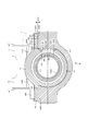
- FIG. 11 is a cross-sectional view taken along the line AA of FIG.
- FIG. 11 is a cross-sectional view taken along the line BB of FIG. 10 showing a state where the steering lock device is attached to the column.
- FIG. 11 is a cross-sectional view taken along the line CC of FIG. 10 showing a state where the steering lock device is attached to the column. It is the P section expanded sectional view of FIG.
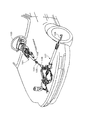
- FIG. 1 is an overall perspective view showing a state in which a steering device 101 according to an embodiment of the present invention is attached to a vehicle.
- the steering device 101 pivotally supports a steering shaft 102 so as to be rotatable.
- a steering wheel 103 is attached to the upper end (rear side of the vehicle body) of the steering shaft 102, and an intermediate shaft 105 is connected to the lower end of the steering shaft 102 (front side of the vehicle body) via a universal joint 104.
- a universal joint 106 is connected to the lower end of the intermediate shaft 105, and a steering gear 107 including a rack and pinion mechanism is connected to the universal joint 106.
- FIG. 2 is a perspective view of the main part of the steering device 101 according to the embodiment of the present invention as viewed from the upper left on the rear side of the vehicle body.
- FIG. 3 is a perspective view of the steering device 101 according to the embodiment of the present invention, with the vehicle body mounting bracket omitted and seen from the upper right on the rear side of the vehicle body.
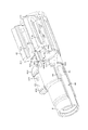
- FIG. 4 shows a state before the steering lock device is attached to the column, and is a perspective view seen from the upper right on the rear side of the vehicle body.
- FIG. 5 is a perspective view showing the single column of FIG. 4 as seen from the upper right on the rear side of the vehicle body.
- FIG. 6 is an enlarged plan view of the periphery of a flange portion showing a single column
- FIG. 7 is a perspective view of the single column of FIG. 4 as viewed from the lower right on the rear side of the vehicle body.
- FIG. 8 is an enlarged perspective view of the periphery of the flange portion of the single column of FIG. 7 as viewed from the lower right on the rear side of the vehicle body.
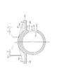
- FIG. 9 is a front view of the single column of FIG. 4 as viewed from the right side in the vehicle width direction.
- FIG. 10 is an enlarged front view showing the vicinity of the flange portion of the single column of FIG. 9 as seen from the right side in the vehicle width direction.
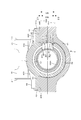
- FIG. 11 is a cross-sectional view taken along the line AA in FIG. 10, and FIG. 12 is a cross-sectional view taken along the line AA in FIG. 10, showing a state where the steering lock device is attached to the column.
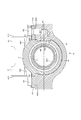
- 13 is a cross-sectional view taken along the line BB of FIG. 10, showing a state in which the steering lock device is attached to the column.
- 14 is a cross-sectional view taken along the line CC of FIG. 10, showing a state in which the steering lock device is attached to the column.
- FIG. 15 is an enlarged cross-sectional view of a portion P in FIG.
- the steering device 101 includes a vehicle body mounting bracket 2, an inner column (lower column) 3, an outer column (upper column) 4, and the like.
- the vehicle body mounting bracket 2 is fixed to a vehicle body (not shown) via a capsule 23.
- the outer column 4 is made of an aluminum alloy and is formed by casting such as die casting.
- An upper steering shaft 102A is rotatably supported on the outer column 4, and a steering wheel 103 (see FIG. 1) is fixed to an end portion of the upper steering shaft 102A on the vehicle body rear side.
- an assist device (steering assisting portion) 5 for applying assist torque is attached.
- An electric motor 52 is fixed to the gear housing 51 of the assist device 5, and a worm wheel of the gear housing 51 is engaged with a worm coupled to a rotating shaft (not shown) of the electric motor 52.
- the direction and magnitude of torque applied from the steering wheel 103 to the upper steering shaft 102A are detected by a torque sensor.
- the electric motor 52 is driven to generate auxiliary torque with a predetermined magnitude in a predetermined direction via a speed reduction mechanism composed of a worm and a worm wheel.
- the end of the gear housing 51 on the front side of the vehicle body is pivotally supported by the vehicle body so that the tilt position can be adjusted with a tilt center axis (not shown) as a fulcrum.
- Clamp members 41, 41 are formed on the vehicle body upper side of the outer column 4 so as to protrude from the vehicle body upper side on the left and right sides in the vehicle width direction. As shown in FIGS. 2 to 15, the outer surfaces 411, 411 of the clamp members 41, 41 are sandwiched between the left and right side plates 24, 24 of the vehicle body mounting bracket 2 so as to be capable of tilt sliding and telescopic sliding. Yes.
- the telescopic adjustment long grooves 412 and 412 which are long in the axial direction of the outer column 4 are formed in the clamp members 41 and 41. Further, the left and right side plates 24, 24 of the vehicle body mounting bracket 2 are formed with long slots 25, 25 for tilt adjustment that are long in the vertical direction of the vehicle body. Round rod-like tightening rods 21 are inserted into the long grooves 25 and 25 for tilt adjustment and the long grooves 412 and 412 for telescopic adjustment.
- a slit 42 communicating from the outer peripheral surface of the outer column 4 to the inner peripheral surface is formed on the vehicle body upper side of the outer column 4.
- the slit 42 is formed long between the clamp members 41, 41 in the axial direction of the outer column 4.
- the hollow cylindrical outer column 4 is integrally formed with a pair of flange portions 43 and 44 on the left and right sides in the vehicle width direction on the rear side of the vehicle body.
- the flange portions 43 and 44 are formed to protrude outward in the radial direction at opposing positions on the outer periphery of the outer column 4.
- Bolt holes 431 and 441 are formed in the flange portions 43 and 44, respectively.
- the bolt hole 431 is formed in the vicinity of the end of the left flange portion 43 on the front side of the vehicle body (the right side in FIGS. 3 and 6) when viewed from the rear side of the vehicle body. Is formed near the end of the right flange portion 44 on the vehicle body rear side (left side in FIGS. 3 and 6) when viewed from the vehicle body rear side.
- flange-like ribs 432 and 433 are formed integrally with the flange portion 43 in the left flange portion 43, and the outer peripheral surface of the flange portion 43 and the outer column 4 is formed.
- the flange part 43 is reinforced by connecting.
- One rib 432 is formed on the vehicle body rear side (left side in FIGS. 3 and 6) of the left flange portion 43, and the other rib 433 is on the vehicle body front side (FIGS. 3 and 6) of the left flange portion 43. It is formed on the right side).
- the right flange portion 44 has flange-shaped ribs 442 and 443 formed integrally with the flange portion 43, and connects the flange portion 44 and the outer peripheral surface of the outer column 4 to reinforce the flange portion 44. ing.
- One rib 442 is formed on the vehicle body front side (the right side in FIGS. 3 and 6) of the right flange portion 44, and the other rib 443 is formed integrally with the rib 442 on the vehicle body front side of the one rib 442. Has been.
- the ribs 432, 433, 442, and 443 are formed such that the thickness in the direction orthogonal to the axial direction of the outer column 4 increases toward the center side of the outer column 4.
- the ribs 433 and 443 on the front side of the vehicle body are formed to extend toward the center side of the outer column 4 than the ribs 432 and 442 on the rear side of the vehicle body.
- the ribs 433 and 443 extend to the vicinity of the closed end portion 421 on the rear side of the vehicle body of the slit 42, thereby improving the strength of the closed end portion 421 of the slit 42 where stress is concentrated during telescopic clamping.
- thin portions 434 and 444 are formed on the outer peripheral surface of the outer column 4 in the vicinity of the connection portion between the parallel portion 422 and the closed end portion 421.
- a housing 61 of the steering lock device 6 is attached.
- the attachment surface 435 and the attachment surface 445 are formed in parallel to the axial direction of the outer column 4.
- An arc-shaped concave surface 62 is formed on the upper part of the aluminum alloy housing 61, and flat clamping surfaces 63, 63 are formed on both ends of the arc-shaped concave surface 62 in the vehicle width direction.
- Female screws 64 and 64 are formed on the fastening surfaces 63 and 63, respectively. The female screws 64, 64 are formed at positions aligned with the bolt holes 431, 441 of the flange portions 43, 44.
- the elliptical lock pin 66 projects from the elliptical engagement convex portion 65 formed on the right side surface of the arcuate concave surface 62.
- the engaging convex portion 65 is formed so as to protrude from the arc-shaped concave surface 62 toward the outer peripheral surface of the outer column 4.
- a key lock collar 67 is press-fitted into the outer periphery of the upper steering shaft 102A, and the tip of the protruding lock pin 66 engages with a key lock hole 671 of the key lock collar 67 to lock the steering wheel 103 from turning.
- a through hole 45 is formed on the right side surface of the outer column 4.
- the through hole 45 is formed in an elliptical shape having a slight gap with the outer peripheral surface of the lock pin 66.
- the through hole 45 is formed by shifting the phase on the circumference of the outer column 4 by 90 degrees with respect to the slit 42.
- a bottomed guide groove 46 is formed on the right side surface of the outer column 4.
- the guide groove 46 is formed in parallel to the axial direction of the outer column 4 so as to extend from the vicinity of the elliptical through hole 45 to the vehicle body rear end (left end in FIG. 4) of the outer column 4.
- the width (groove width) W1 (see FIG. 12) of the guide groove 46 in the vertical direction of the vehicle body is formed to be slightly larger than the vertical width W2 of the engagement convex portion 65 of the steering lock device 6.
- a closed end (see FIG. 4) 462 is formed in the guide groove 46 on the front side of the vehicle body with respect to the elliptical through hole 45, and the vehicle body rear end of the outer column 4 is opened.
- An arcuate concave surface (a surface facing the bottom surface 461) 651 is formed at the tip of the engaging convex portion 65.
- the outer diameter R1 (see FIG. 12) R1 of the bottom surface 461 of the guide groove 46 is slightly smaller than the inner diameter R2 of the arcuate concave surface 651.
- the engaging protrusion 65 of the steering lock device 6 is inserted into the rear end of the vehicle body of the guide groove 46, and the steering lock device 6 is slid along the guide groove 46 to the front side of the vehicle body.
- the female screws 64, 64 of the housing 61 of the steering lock device 6 are connected to the flange portions 43, 44. It is positioned at a position aligned with the bolt holes 431 and 441.
- the lock pin 66 of the steering lock device 6 is positioned at a position aligned with the key lock hole 671 of the key lock collar 67.
- the bolts 68 and 68 are inserted into the bolt holes 431 and 441, the bolts 68 and 68 are screwed into the female screws 64 and 64, and the housing 61 is attached to the outer column 4.
- the fastening surface 63 of the housing 61 of the steering lock device 6 is mounted on the mounting surface 435 on the vehicle body lower side of the flange portion 43 and the ribs 432 and 433 and the mounting surface 445 on the vehicle body lower side of the flange portion 44 and ribs 442 and 443. 63 are in close contact with each other.
- relief portions 47 and 48 are formed on the attachment surface 445 of the right flange portion 44 in the vicinity of the bolt hole 441.
- the escape portions 47 and 48 are formed to be recessed from the mounting surface 445 by ⁇ 3 (see FIGS. 13 and 15).
- One relief portion 47 is formed on the vehicle body rear side (left side in FIG. 8) of the bolt hole 441
- the other relief portion 48 is formed on the vehicle body front side (right side in FIG. 8) of the bolt hole 441.
- the escape portions 47 and 48 are formed to extend from the outer side surface 446 of the flange portion 44 in the vehicle width direction to the root of the flange portion 44 (the connection portion between the flange portion 44 and the outer peripheral surface of the outer column 4).
- corner R portions 471 and 481 are formed at connection portions between the escape portions 47 and 48 and the outer peripheral surface of the outer column 4. Since the escape portions 47 and 48 are formed to be recessed by ⁇ 3 from the attachment surface 445, the radius R1 (see FIG. 15) of the corner R portions 471 and 481 of the escape portions 47 and 48 is the corner R of the attachment surface 445.
- the portion 447 can be formed larger than the radius R2. Accordingly, it is possible to avoid interference with the corner 631 at the inner end of the tightening surface 63 of the steering lock device 6 in the vehicle width direction.
- a flange portion 44, a rib 442, and a rib 443 are formed between the through hole 45 through which the lock pin 66 enters and exits and the slit 42 for reducing the inner peripheral surface of the outer column 4.
- the strength of is increased. Accordingly, both the strength of the outer column 4 with respect to the bending moment applied to the lock pin 66 when the key is locked and the strength of the outer column 4 when the inner peripheral surface of the outer column 4 is reduced in diameter and telescopically clamped can be ensured. .
- the relief portions 47 and 48 are formed in the vicinity of the bolt hole 441 of the mounting surface 445 of the right flange portion 44, but in the vicinity of the bolt hole 431 of the mounting surface 435 of the left flange portion 43.
- An escape portion may be formed.
- relief portions may be formed both in the vicinity of the right bolt hole 441 and in the vicinity of the left bolt hole 431.
- the outer column is formed with the aluminum alloy, you may form with a magnesium alloy or resin.
Landscapes
- Engineering & Computer Science (AREA)
- Mechanical Engineering (AREA)
- Steering Controls (AREA)
Abstract
ステアリングロック装置を備えたステアリング装置において、ステアリングロック装置が取り付けられるコラムの貫通孔の周囲に作用する応力を緩和する。 ロックピン66の外周面と貫通孔45との間、及び、案内溝46と係合凸部65との間には、車体上下方向に若干の隙間が形成されているため、貫通孔45には力が加わらず、フランジ部43、リブ432、433、及び、フランジ部44、リブ442、443だけで力を受ける。貫通孔45には、係合凸部65は嵌合しない。貫通孔45は、係合凸部65よりも断面積の小さなロックピン66が出入りする程度の大きさで済むため、貫通孔45の面積が小さくて済み、アウターコラム4の強度を向上させることができる。
Description
本発明はステアリング装置、特に、イグニションキーをロック位置に回して鍵穴から引き抜くと、自動車の盗難防止のため、ステアリングホイールが回らないようにロックするステアリングロック装置を有するステアリング装置に関する。
ステアリングロック装置を有するステアリング装置においては、イグニションキーをロック位置に回して鍵穴から引き抜くと、ロックピンがステアリングシャフトの軸心側に向かって突出する。その結果、ステアリングシャフトの外周に圧入されたキーロックカラーのキーロック孔に、ロックピンの先端が係合して、ステアリングシャフトをアウターコラムに対して固定して、ステアリングシャフトの回転を阻止するようにしている。
従来のステアリングロック装置を備えたステアリング装置は、ステアリングロック装置を収納するハウジングをコラムとは別部品で構成し、コラムに形成された貫通孔にハウジングの係合凸部を嵌合して位置決めした後、コラムのフランジ部にハウジングをボルトを使って取り付けている。
しかし、コラムがアルミニウム合金製の場合には、コラムの強度が小さい。従って、貫通孔に係合凸部が嵌合した状態で、フランジ部にハウジングをボルトを使って締め付けると、ボルトの締付け力がコラムの貫通孔の周囲に作用し、コラムに亀裂が生じる恐れがある。また、キーロック時(ロックピンがキーロック孔に係合した状態)に、ステアリングホイールに大きな回転トルクが加わると、ロックピンに加わる曲げモーメントによって、コラムの貫通孔の周囲に大きな応力が加わり、コラムに亀裂が生じる恐れがある。
特許文献1に示すステアリング装置は、板厚の厚い鋼板製のフランジ部を鋼管製のコラムに溶接することによって、コラムとステアリングロック装置のハウジングとの取付剛性を大きくしている。また、ステアリングロック装置の係合凸部をコラムの貫通孔に密に嵌合して、フランジ部と貫通孔の両方で、キーロック時にロックピンに加わる曲げモーメントを受けるようにしている。しかし、特許文献1に示すステアリング装置は、鋼管製のコラムに適用したものであって、アルミニウム合金製のコラムの貫通孔の周囲に作用する応力を緩和する対策については記載されていない。
本発明は、ステアリングロック装置を備えたステアリング装置において、ステアリングロック装置が取り付けられるコラムの貫通孔の周囲に作用する応力を緩和するようにしたステアリング装置を提供することを課題とする。
上記課題は以下の手段によって解決される。すなわち、第1番目の発明は、コラムに回転可能に軸支され、車体後方側にステアリングホイールを装着可能なステアリングシャフト、上記コラムに取り付けられ、イグニションキーの操作によって作動するロックピンを上記ステアリングシャフトに係合して、ステアリングシャフトが回らないようにロックするステアリングロック装置、上記ステアリングロック装置に上記コラムの外周面に向かって突出して形成され、上記コラムに対してステアリングロック装置を位置決めする係合凸部、上記コラムの外周面から半径方向外側に突出してコラムに一体的に形成され、上記ステアリングロック装置を収納するハウジングを取り付ける取付面が形成されたフランジ部、上記ハウジングを上記取付面に締め付けるボルト、上記コラムに形成され、上記ロックピンの外周面との間に隙間を有して形成された貫通孔、上記コラムの外周面にコラムの軸方向に平行に形成され、コラムの軸方向の端部から上記貫通孔近傍まで上記係合凸部を案内し、係合凸部の幅よりも広い溝幅を有する案内溝を備えたことを特徴とするステアリング装置である。
第2番目の発明は、第1番目の発明のステアリング装置において、上記ボルトで上記ハウジングを上記取付面に締め付けた時に、上記案内溝の側面と上記係合凸部との間に隙間が形成されることを特徴とするステアリング装置である。
第3番目の発明は、第1番目の発明のステアリング装置において、上記案内溝の底面の外径が上記係合凸部の先端の円弧状の凹面の内径よりも小さく形成されていることを特徴とするステアリング装置である。
第4番目の発明は、第2番目の発明のステアリング装置において、上記案内溝の底面の外径が上記係合凸部の先端の円弧状の凹面の内径よりも小さく形成されていることを特徴とするステアリング装置である。
第5番目の発明は、第1番目から第4番目までのいずれかの発明のステアリング装置において、上記コラムがアルミニウム合金またはマグネシウム合金で形成されていることを特徴とするステアリング装置である。
本発明のステアリング装置は、ステアリングロック装置にコラムの外周面に向かって突出して形成され、コラムに対してステアリングロック装置を位置決めする係合凸部と、コラムの外周面から半径方向外側に突出してコラムに一体的に形成され、ステアリングロック装置を収納するハウジングを取り付ける取付面が形成されたフランジ部と、ハウジングを取付面に締め付けるボルトと、コラムに形成され、ロックピンの外周面との間に隙間を有して形成された貫通孔と、コラムの外周面にコラムの軸方向に平行に形成され、コラムの軸方向の端部から貫通孔近傍まで係合凸部を案内し、係合凸部の幅よりも広い溝幅を有する案内溝を備えている。
従って、貫通孔は、係合凸部よりも断面積の小さなロックピンが出入りする程度の大きさで済むため、貫通孔の面積が小さくて済み、コラムの強度を向上させることができる。また、ロックピンの外周面と貫通孔との間、及び、案内溝と係合凸部との間には、隙間が形成されているため、ロックピンに加わる曲げモーメント及びボルトの締付け力は、貫通孔には加わらず、貫通孔の周囲に作用する応力を緩和することができる。
図1は本発明の実施例のステアリング装置101を車両に取り付けた状態を示す全体斜視図である。ステアリング装置101は、ステアリングシャフト102を回動自在に軸支している。ステアリングシャフト102には、その上端(車体後方側)にステアリングホイール103が装着され、ステアリングシャフト102の下端(車体前方側)には、ユニバーサルジョイント104を介して中間シャフト105が連結されている。
中間シャフト105にはその下端にユニバーサルジョイント106が連結され、ユニバーサルジョイント106には、ラックアンドピニオン機構等からなるステアリングギヤ107が連結されている。
運転者がステアリングホイール103を回転操作すると、ステアリングシャフト102、ユニバーサルジョイント104、中間シャフト105、ユニバーサルジョイント106を介して、その回転力がステアリングギヤ107に伝達され、ラックアンドピニオン機構を介して、タイロッド108を移動し、車輪の操舵角を変えることができる。
図2は本発明の実施例のステアリング装置101の要部を車体後方側の左上方から見た斜視図である。図3は本発明の実施例のステアリング装置101から車体取付けブラケットを省略し、車体後方側の右上方から見た斜視図である。図4はステアリングロック装置をコラムに取り付ける前の状態を示し、車体後方側の右上方から見た斜視図である。図5は図4のコラム単体を示し、車体後方側の右上方から見た斜視図である。
図6はコラム単体を示すフランジ部周辺の拡大平面図、図7は図4のコラム単体を示し、車体後方側の右下方から見た斜視図である。図8は図7のコラム単体のフランジ部周辺を、車体後方側の右下方から見た拡大斜視図である。図9は図4のコラム単体を示し、車幅方向の右側から見た正面図である。図10は図9のコラム単体のフランジ部近傍を示し、車幅方向の右側から見た拡大正面図である。
図11は図10のA-A断面図、図12はステアリングロック装置をコラムに取り付けた状態を示す、図10のA-A断面図である。図13はステアリングロック装置をコラムに取り付けた状態を示す、図10のB-B断面図である。図14はステアリングロック装置をコラムに取り付けた状態を示す、図10のC-C断面図である。図15は図13のP部拡大断面図である。
図2に示すように、本発明の実施例のステアリング装置101は、車体取付けブラケット2、インナーコラム(ロアーコラム)3、アウターコラム(アッパーコラム)4等から構成されている。車体取付けブラケット2は、カプセル23を介して図示しない車体に固定されている。
円筒状のインナーコラム3の車体後方側(図2の右側)の外周面には、中空円筒状のアウターコラム4の内周面がテレスコピック位置調整(インナーコラム3の中心軸線に平行に摺動)可能に外嵌している。アウターコラム4は、材質がアルミニウム合金で、ダイカスト等の鋳造によって成形されている。アウターコラム4には、上部ステアリングシャフト102Aが回動可能に軸支され、上部ステアリングシャフト102Aの車体後方側の端部には、ステアリングホイール103(図1参照)が固定されている。
インナーコラム3の車体前方側には、補助トルクを付与する為のアシスト装置(操舵補助部)5が取り付けられている。アシスト装置5のギヤハウジング51には、電動モータ52が固定され、この電動モータ52の図示しない回転軸に結合されたウォームに、ギヤハウジング51のウォームホイールが噛合っている。
ステアリングホイール103から上部ステアリングシャフト102Aに加えられるトルクの方向と大きさを、トルクセンサで検出している。このトルクセンサの検出値に応じて、電動モータ52を駆動し、ウォームとウォームホイールから成る減速機構を介して、所定の方向に所定の大きさで補助トルクを発生させる。
ギヤハウジング51の車体前方側の端部は、図示しないチルト中心軸を支点として、車体にチルト位置調整可能に軸支されている。アウターコラム4の車体上方側には、車幅方向の左右両側に、クランプ部材41、41が車体上方側に突出して形成されている。図2から図15に示すように、クランプ部材41、41の外側面411、411は、車体取付けブラケット2の左右の側板24、24に、チルト摺動、並びに、テレスコピック摺動可能に挟持されている。
クランプ部材41、41には、アウターコラム4の軸方向に長いテレスコ調整用長溝412、412が形成されている。また、車体取付けブラケット2の左右の側板24、24には、車体上下方向に長いチルト調整用長溝25、25が形成されている。チルト調整用長溝25、25とテレスコ調整用長溝412、412には、丸棒状の締付けロッド21が挿入されている。
締付けロッド21の端部に装着された操作レバー22を揺動操作すると、カムロック機構26が作動し、車体取付けブラケット2の左右の側板24、24が締付けられる。その結果、アウターコラム4の左右のクランプ部材41、41が、車体取付けブラケット2の左右の側板24、24に強く締め付けられる。
アウターコラム4の車体上方側には、アウターコラム4の外周面から内周面に連通するスリット42が形成されている。スリット42は、クランプ部材41、41の間に、アウターコラム4の軸方向に長く形成されている。車体取付けブラケット2の左右の側板24、24が締付けられると、スリット42の車幅方向の間隔が縮まって、アウターコラム4の内周面が縮径し、インナーコラム3の外周面を強く締め付ける。そのため、所望のチルト位置及びテレスコピック位置で、アウターコラム4が車体取付けブラケット2にクランプされる。
中空円筒形状のアウターコラム4には、車体後方側の車幅方向の左右両側に、一対のフランジ部43、44が一体的に形成されている。フランジ部43、44は、アウターコラム4の外周の対向する位置に、半径方向外側に突出して形成されている。フランジ部43、44には、各々ボルト孔431、441が形成されている。図3、図6に示すように、ボルト孔431は、車体後方側から見て左側のフランジ部43の車体前方側(図3、図6の右側)の端部近傍に形成され、ボルト孔441は、車体後方側から見て右側のフランジ部44の車体後方側(図3、図6の左側)の端部近傍に形成されている。
また、図3、図6に示すように、左側のフランジ部43には、フランジ状のリブ432と433が、フランジ部43と一体的に形成され、フランジ部43とアウターコラム4の外周面を接続して、フランジ部43を補強している。一方のリブ432は、左側のフランジ部43の車体後方側(図3、図6の左側)に形成され、他方のリブ433は、左側のフランジ部43の車体前方側(図3、図6の右側)に形成されている。また、右側のフランジ部44には、フランジ状のリブ442と443が、フランジ部43と一体的に形成され、フランジ部44とアウターコラム4の外周面を接続して、フランジ部44を補強している。一方のリブ442は、右側のフランジ部44の車体前方側(図3、図6の右側)に形成され、他方のリブ443は一方のリブ442の車体前方側に、リブ442と一体的に形成されている。
リブ432、433、442、443は、アウターコラム4の軸方向に直交する方向の厚さが、アウターコラム4の中心側に行くほど厚くなるように形成されている。車体前方側のリブ433、443は、車体後方側のリブ432、442よりもアウターコラム4の中心側に延びて形成されている。その結果、リブ433、443は、スリット42の車体後方側の閉鎖端部421近傍まで延びていて、テレスコピッククランプ時に応力が集中するスリット42の閉鎖端部421の強度を向上させている。
また、スリット42の平行部422の車幅方向外側には、平行部422と閉鎖端部421との接続部近傍に、アウターコラム4の外周面に薄肉部434、444が形成されている。薄肉部434、444を形成することで、テレスコピッククランプ時に、スリット42の平行部422の溝幅を縮小させるための力が小さくてすむため、インナーコラム3の外周面を強く締め付けるのが容易で、テレスコピッククランプ力を大きくすることができる。
図4及び図11から図15に示すように、フランジ部43、リブ432、433の車体下方側の取付面435、及び、フランジ部44、リブ442、443の車体下方側の取付面445に、ステアリングロック装置6のハウジング61が取り付けられる。取付面435及び取付面445は、アウターコラム4の軸方向に平行に形成されている。アルミニウム合金製のハウジング61の上部には、円弧状の凹面62が形成され、円弧状の凹面62の車幅方向の両端には、平坦な締付け面63、63が形成されている。締付け面63、63には、雌ねじ64、64が各々形成されている。雌ねじ64、64は、フランジ部43、44のボルト孔431、441と整合する位置に形成されている。
図示しないイグニションキーをロック位置に回して鍵穴から引き抜くと、円弧状の凹面62の右側面に形成された楕円形の係合凸部65から楕円形のロックピン66が突出する。係合凸部65は、円弧状の凹面62からアウターコラム4の外周面に向かって突出して形成されている。上部ステアリングシャフト102Aの外周にはキーロックカラー67が圧入され、突出したロックピン66の先端は、キーロックカラー67のキーロック孔671に係合し、ステアリングホイール103が回らないようにロックする。
アウターコラム4の右側面には貫通孔45が形成されている。貫通孔45は、ロックピン66の外周面との間に若干の隙間を有する大きさの楕円形に形成されている。貫通孔45は、スリット42に対して、アウターコラム4の円周上の位相を90度ずらして形成されている。また、アウターコラム4の右側面には、有底の案内溝46が形成されている。案内溝46は、アウターコラム4の軸方向に平行に、楕円形の貫通孔45近傍からアウターコラム4の車体後方端(図4の左端)まで延びて形成されている。案内溝46の車体上下方向の幅(溝幅)W1(図12参照)は、ステアリングロック装置6の係合凸部65の車体上下方向の幅W2よりも若干大きく形成されている。
また、案内溝46には、楕円形の貫通孔45よりも車体前方側に閉鎖端部(図4参照)462が形成され、アウターコラム4の車体後方端が開放されている。係合凸部65の先端には、円弧状の凹面(底面461と対向する面)651が形成されている。案内溝46の底面461の外径(図12参照)R1は、円弧状の凹面651の内径R2よりも若干小さく形成されている。
図4に示すように、ステアリングロック装置6の係合凸部65を案内溝46の車体後方端に挿入し、案内溝46に沿ってステアリングロック装置6を車体前方側に摺動して組み付ける。図3に示すように、係合凸部65の車体前方端が案内溝46の閉鎖端部462に当接すると、ステアリングロック装置6のハウジング61の雌ねじ64、64が、フランジ部43、44のボルト孔431、441と整合する位置に位置決めされる。また、ステアリングロック装置6のロックピン66が、キーロックカラー67のキーロック孔671と整合する位置に位置決めされる。
この状態で、ボルト68、68をボルト孔431、441に挿入し、雌ねじ64、64にボルト68、68をねじ込んで締付け、ハウジング61をアウターコラム4に取り付ける。すると、フランジ部43、リブ432、433の車体下方側の取付面435、及び、フランジ部44、リブ442、443の車体下方側の取付面445に、ステアリングロック装置6のハウジング61の締付け面63、63が密着する。
この時、図12に示すように、案内溝46の側面463、463と係合凸部65の側面(図12参照)652、652との間には、車体上下方向に若干の隙間β1、β2が形成される。また、ロックピン66の外周面とアウターコラム4の貫通孔45との間にも、若干の隙間が形成される。
キーロック時(ロックピン66がキーロック孔671に係合した状態)に、ステアリングホイール103に大きな回転トルクが加わると、ロックピン66に曲げモーメントが加わる。また、ボルト68、68を締め付けると、ステアリングロック装置6のハウジング61に車体上方への締付け力が作用する。
しかし、ロックピン66の外周面と貫通孔45との間、及び、案内溝46と係合凸部65との間には、車体上下方向に若干の隙間が形成されているため、貫通孔45には力が加わらず、フランジ部43、リブ432、433、及び、フランジ部44、リブ442、443だけで力を受ける。貫通孔45には、係合凸部65は嵌合しない。貫通孔45は、係合凸部65よりも断面積の小さなロックピン66が出入りする程度の大きさで済むため、貫通孔45の面積が小さくて済み、アウターコラム4の強度を向上させることができる。
図7、図8、図10、図13、図15に示すように、右側のフランジ部44の取付面445には、ボルト孔441の近傍に、逃げ部47、48が形成されている。逃げ部47、48は、取付面445よりもβ3(図13、図15参照)だけ窪んで形成されている。一方の逃げ部47は、ボルト孔441の車体後方側(図8の左側)に形成され、他方の逃げ部48は、ボルト孔441の車体前方側(図8の右側)に形成されている。逃げ部47、48は、フランジ部44の車幅方向の外側面446から、フランジ部44の根元(フランジ部44とアウターコラム4の外周面との接続部)まで延びて形成されている。
逃げ部47、48には、逃げ部47、48とアウターコラム4の外周面との接続部に、コーナーR部471、481が形成されている。逃げ部47、48は、取付面445よりもβ3だけ窪んで形成されているため、逃げ部47、48のコーナーR部471、481の半径R1(図15参照)は、取付面445のコーナーR部447の半径R2よりも大きく形成することができる。従って、ステアリングロック装置6の締付け面63の車幅方向の内端の角部631との干渉を回避することができる。
また、キーロック時に、ステアリングホイール103に大きな回転トルクが加わり、ロックピン66に曲げモーメントが加わると、ボルト孔441近傍のフランジ部44の根元に大きな応力が作用する。しかし、コーナーR部471、481の半径R1を大きく形成することにより、コーナーR部471、481に作用する応力を緩和することができる。
また、ロックピン66が出入りする貫通孔45と、アウターコラム4の内周面を縮径するためのスリット42との間に、フランジ部44、リブ442、リブ443が形成されて、アウターコラム4の強度を大きくしている。従って、キーロック時にロックピン66に加わる曲げモーメントに対するアウターコラム4の強度と、アウターコラム4の内周面を縮径してテレスコピッククランプする時のアウターコラム4の強度の両方を確保することができる。
上記実施例では、右側のフランジ部44の取付面445のボルト孔441の近傍に、逃げ部47、48を形成しているが、左側のフランジ部43の取付面435のボルト孔431の近傍に逃げ部を形成してもよい。また、右側のボルト孔441の近傍と左側のボルト孔431の近傍の両方に逃げ部を形成してもよい。さらに、上記実施例では、アウターコラムがアルミニウム合金で形成されているが、マグネシウム合金や樹脂で形成してもよい。
101 ステアリング装置
102 ステアリングシャフト
102A 上部ステアリングシャフト
103 ステアリングホイール
104 ユニバーサルジョイント
105 中間シャフト
106 ユニバーサルジョイント
107 ステアリングギヤ
108 タイロッド
2 車体取付けブラケット
21 締付けロッド
22 操作レバー
23 カプセル
24 側板
25 チルト調整用長溝
26 カムロック機構
3 インナーコラム(ロアーコラム)
4 アウターコラム(アッパーコラム)
41 クランプ部材
411 外側面
412 テレスコ調整用長溝
42 スリット
421 閉鎖端部
422 平行部
43 フランジ部
431 ボルト孔
432、433 リブ
434 薄肉部
435 取付面
44 フランジ部
441 ボルト孔
442、443 リブ
444 薄肉部
445 取付面
446 車幅方向の外側面
447 コーナーR部
45 貫通孔
46 案内溝
461 底面
462 閉鎖端部
463 側面
47、48 逃げ部
471、481 コーナーR部
5 アシスト装置(操舵補助部)
51 ギヤハウジング
52 電動モータ
6 ステアリングロック装置
61 ハウジング
62 円弧状の凹面
63 締付け面
631 角部
64 雌ねじ
65 係合凸部
651 円弧状の凹面
652 側面
66 ロックピン
67 キーロックカラー
671 キーロック孔
68 ボルト
Claims (5)
- コラムに回転可能に軸支され、車体後方側にステアリングホイールを装着可能なステアリングシャフト、
上記コラムに取り付けられ、イグニションキーの操作によって作動するロックピンを上記ステアリングシャフトに係合して、ステアリングシャフトが回らないようにロックするステアリングロック装置、
上記ステアリングロック装置に上記コラムの外周面に向かって突出して形成され、上記コラムに対してステアリングロック装置を位置決めする係合凸部、
上記コラムの外周面から半径方向外側に突出してコラムに一体的に形成され、上記ステアリングロック装置を収納するハウジングを取り付ける取付面が形成されたフランジ部、
上記ハウジングを上記取付面に締め付けるボルト、
上記コラムに形成され、上記ロックピンの外周面との間に隙間を有して形成された貫通孔、
上記コラムの外周面にコラムの軸方向に平行に形成され、コラムの軸方向の端部から上記貫通孔近傍まで上記係合凸部を案内し、係合凸部の幅よりも広い溝幅を有する案内溝を備えたこと
を特徴とするステアリング装置。 - 請求項1に記載されたステアリング装置において、
上記ボルトで上記ハウジングを上記取付面に締め付けた時に、
上記案内溝の側面と上記係合凸部との間に隙間が形成されること
を特徴とするステアリング装置。 - 請求項1に記載されたステアリング装置において、
上記案内溝の底面の外径が上記係合凸部の先端の円弧状の凹面の内径よりも小さく形成されていること
を特徴とするステアリング装置。 - 請求項2に記載されたステアリング装置において、
上記案内溝の底面の外径が上記係合凸部の先端の円弧状の凹面の内径よりも小さく形成されていること
を特徴とするステアリング装置。 - 請求項1から請求項4までのいずれかに記載されたステアリング装置において、
上記コラムがアルミニウム合金またはマグネシウム合金で形成されていること
を特徴とするステアリング装置。
Priority Applications (3)
| Application Number | Priority Date | Filing Date | Title |
|---|---|---|---|
| US13/376,975 US8869646B2 (en) | 2010-08-20 | 2011-07-13 | Steering device |
| EP11790843.4A EP2607201B1 (en) | 2010-08-20 | 2011-07-13 | Steering device |
| CN201180001069.0A CN102448794B (zh) | 2010-08-20 | 2011-07-13 | 转向装置 |
Applications Claiming Priority (2)
| Application Number | Priority Date | Filing Date | Title |
|---|---|---|---|
| JP2010-184973 | 2010-08-20 | ||
| JP2010184973A JP5429109B2 (ja) | 2010-08-20 | 2010-08-20 | ステアリング装置 |
Publications (1)
| Publication Number | Publication Date |
|---|---|
| WO2012023366A1 true WO2012023366A1 (ja) | 2012-02-23 |
Family
ID=45605027
Family Applications (1)
| Application Number | Title | Priority Date | Filing Date |
|---|---|---|---|
| PCT/JP2011/065941 WO2012023366A1 (ja) | 2010-08-20 | 2011-07-13 | ステアリング装置 |
Country Status (5)
| Country | Link |
|---|---|
| US (1) | US8869646B2 (ja) |
| EP (1) | EP2607201B1 (ja) |
| JP (1) | JP5429109B2 (ja) |
| CN (1) | CN102448794B (ja) |
| WO (1) | WO2012023366A1 (ja) |
Cited By (1)
| Publication number | Priority date | Publication date | Assignee | Title |
|---|---|---|---|---|
| US9463773B2 (en) * | 2013-04-18 | 2016-10-11 | Nsk Ltd. | Steering lock apparatus |
Families Citing this family (7)
| Publication number | Priority date | Publication date | Assignee | Title |
|---|---|---|---|---|
| US20110088501A1 (en) * | 2009-10-20 | 2011-04-21 | Mando Corporation | Steering column for vehicle |
| EP2559599B1 (en) * | 2010-04-12 | 2017-05-24 | NSK Ltd. | Steering device |
| JP6447622B2 (ja) * | 2014-03-03 | 2019-01-09 | 日本精工株式会社 | テレスコピックステアリング装置用アウタコラム及びテレスコピックステアリング装置 |
| JP6497543B2 (ja) * | 2015-01-22 | 2019-04-10 | 株式会社ジェイテクト | ステアリング装置 |
| KR102487792B1 (ko) * | 2016-02-05 | 2023-01-13 | 에이치엘만도 주식회사 | 스티어링 시스템용 기어박스의 마운팅부시 |
| JP7409317B2 (ja) * | 2018-11-15 | 2024-01-09 | 日本精工株式会社 | アウタコラムおよびステアリング装置 |
| JP7484323B2 (ja) * | 2020-03-30 | 2024-05-16 | 日本精工株式会社 | ステアリング装置 |
Citations (3)
| Publication number | Priority date | Publication date | Assignee | Title |
|---|---|---|---|---|
| JP2002337663A (ja) | 2001-05-22 | 2002-11-27 | Fuji Heavy Ind Ltd | ステアリングロックの取付構造 |
| JP2007196784A (ja) * | 2006-01-25 | 2007-08-09 | Toyota Motor Corp | ステアリングホイールロック装置 |
| JP2009137309A (ja) * | 2007-11-13 | 2009-06-25 | Nsk Ltd | ステアリング装置 |
Family Cites Families (28)
| Publication number | Priority date | Publication date | Assignee | Title |
|---|---|---|---|---|
| JPS58181657U (ja) * | 1982-05-31 | 1983-12-03 | いすゞ自動車株式会社 | テレスコピツクステアリングのハンドルロツク機構 |
| US5090730A (en) * | 1991-01-23 | 1992-02-25 | Itt Corporation | Vehicle steering column apparatus |
| DE19707067C1 (de) * | 1997-02-22 | 1998-06-25 | Kostal Leopold Gmbh & Co Kg | Lenksäuleneinheit für einen Kraftwagen |
| US6659504B2 (en) * | 2001-05-18 | 2003-12-09 | Delphi Technologies, Inc. | Steering column for a vehicle |
| JP3738200B2 (ja) * | 2001-06-27 | 2006-01-25 | 光洋精工株式会社 | 衝撃吸収ステアリング装置 |
| EP1533201B1 (en) * | 2002-07-17 | 2006-12-06 | Nsk Ltd., | Steering column device |
| AU2003272921A1 (en) * | 2002-10-04 | 2004-04-23 | Nsk Ltd. | Steering column device |
| JP2004314941A (ja) * | 2003-03-31 | 2004-11-11 | Fuji Kiko Co Ltd | 衝撃吸収式ステアリング装置 |
| US7093855B2 (en) * | 2003-12-05 | 2006-08-22 | Delphi Technologies, Inc. | Steering column assembly having clamping mechanism |
| US7178422B2 (en) * | 2004-07-02 | 2007-02-20 | Delphi Technologies, Inc. | Electrical tilt and telescope locking mechanism |
| JP2006111124A (ja) * | 2004-10-14 | 2006-04-27 | Mazda Motor Corp | ステアリングロック装置 |
| US7367589B2 (en) * | 2005-07-15 | 2008-05-06 | Chrysler Llc | Collapsible steering assembly with a stationary reaction surface |
| JP2007331530A (ja) * | 2006-06-14 | 2007-12-27 | Tokai Rika Co Ltd | ステアリングロック装置 |
| US7635149B2 (en) * | 2007-03-21 | 2009-12-22 | Gm Global Technology Operations, Inc. | Rocker-arm lock device of an adjustable steering column assembly |
| US7730804B2 (en) * | 2007-03-21 | 2010-06-08 | Gm Global Technology Operations, Inc. | Central lock device of an adjustable steering column assembly |
| US8047096B2 (en) * | 2007-03-30 | 2011-11-01 | Nexteer (Beijing) Technology Co., Ltd. | Lock mechanism for an adjustable steering column assembly |
| GB0723485D0 (en) * | 2007-11-30 | 2008-01-09 | Trw Das A S | Adjustable steering column assembly |
| JP2009196562A (ja) * | 2008-02-22 | 2009-09-03 | Nsk Ltd | ステアリングロック装置付伸縮式ステアリング装置 |
| CN102438879B (zh) * | 2010-08-05 | 2014-06-18 | 日本精工株式会社 | 冲击吸收式转向装置 |
| WO2012060193A1 (ja) * | 2010-11-02 | 2012-05-10 | 日本精工株式会社 | ステアリングコラム用支持装置 |
| US8534705B2 (en) * | 2010-12-21 | 2013-09-17 | Nsk Ltd. | Steering column support apparatus |
| EP2626276B1 (en) * | 2010-12-28 | 2018-01-03 | NSK Ltd. | Support device for steering column, and assembly method thereof |
| WO2012128171A1 (ja) * | 2011-03-18 | 2012-09-27 | 日本精工株式会社 | ステアリング装置 |
| US8596683B2 (en) * | 2011-04-14 | 2013-12-03 | Nsk Ltd. | Steering apparatus |
| JP5382066B2 (ja) * | 2011-06-03 | 2014-01-08 | 日本精工株式会社 | ステアリング装置 |
| JP2013001242A (ja) * | 2011-06-16 | 2013-01-07 | Jtekt Corp | ステアリング装置 |
| JP5789500B2 (ja) * | 2011-11-29 | 2015-10-07 | 富士機工株式会社 | ステアリングコラム装置 |
| JP2014058200A (ja) * | 2012-09-14 | 2014-04-03 | Yamada Seisakusho Co Ltd | ステアリング装置 |
-
2010
- 2010-08-20 JP JP2010184973A patent/JP5429109B2/ja active Active
-
2011
- 2011-07-13 EP EP11790843.4A patent/EP2607201B1/en active Active
- 2011-07-13 CN CN201180001069.0A patent/CN102448794B/zh active Active
- 2011-07-13 US US13/376,975 patent/US8869646B2/en not_active Expired - Fee Related
- 2011-07-13 WO PCT/JP2011/065941 patent/WO2012023366A1/ja active Application Filing
Patent Citations (3)
| Publication number | Priority date | Publication date | Assignee | Title |
|---|---|---|---|---|
| JP2002337663A (ja) | 2001-05-22 | 2002-11-27 | Fuji Heavy Ind Ltd | ステアリングロックの取付構造 |
| JP2007196784A (ja) * | 2006-01-25 | 2007-08-09 | Toyota Motor Corp | ステアリングホイールロック装置 |
| JP2009137309A (ja) * | 2007-11-13 | 2009-06-25 | Nsk Ltd | ステアリング装置 |
Non-Patent Citations (1)
| Title |
|---|
| See also references of EP2607201A4 * |
Cited By (1)
| Publication number | Priority date | Publication date | Assignee | Title |
|---|---|---|---|---|
| US9463773B2 (en) * | 2013-04-18 | 2016-10-11 | Nsk Ltd. | Steering lock apparatus |
Also Published As
| Publication number | Publication date |
|---|---|
| CN102448794A (zh) | 2012-05-09 |
| EP2607201A1 (en) | 2013-06-26 |
| JP5429109B2 (ja) | 2014-02-26 |
| US8869646B2 (en) | 2014-10-28 |
| CN102448794B (zh) | 2014-03-12 |
| EP2607201A4 (en) | 2014-07-23 |
| EP2607201B1 (en) | 2015-09-09 |
| JP2012040984A (ja) | 2012-03-01 |
| US20120291584A1 (en) | 2012-11-22 |
Similar Documents
| Publication | Publication Date | Title |
|---|---|---|
| JP5429110B2 (ja) | ステアリング装置 | |
| JP5429109B2 (ja) | ステアリング装置 | |
| JP5626342B2 (ja) | ステアリング装置 | |
| JP5076963B2 (ja) | ステアリング装置 | |
| JP5299435B2 (ja) | ステアリング装置 | |
| JP5360017B2 (ja) | ステアリング装置 | |
| JP5358932B2 (ja) | ステアリング装置 | |
| JP5970992B2 (ja) | 電動パワーステアリング装置 | |
| JP5212398B2 (ja) | ステアリング装置 | |
| JP2015051655A (ja) | ステアリング装置 | |
| JP5966700B2 (ja) | 電動パワーステアリング装置 | |
| JP5970989B2 (ja) | 電動パワーステアリング装置 | |
| JP5194752B2 (ja) | ステアリングロック装置 | |
| JP2016203700A (ja) | ステアリング装置用取付け装置 | |
| JP2014234003A (ja) | ステアリングコラム装置 | |
| JP2009056972A (ja) | 車両用ステアリングコラムの支持構造 | |
| JP2015085903A (ja) | 車両用ステアリングコラム装置 |
Legal Events
| Date | Code | Title | Description |
|---|---|---|---|
| WWE | Wipo information: entry into national phase |
Ref document number: 201180001069.0 Country of ref document: CN |
|
| WWE | Wipo information: entry into national phase |
Ref document number: 2011790843 Country of ref document: EP |
|
| 121 | Ep: the epo has been informed by wipo that ep was designated in this application |
Ref document number: 11790843 Country of ref document: EP Kind code of ref document: A1 |
|
| WWE | Wipo information: entry into national phase |
Ref document number: 13376975 Country of ref document: US |
|
| NENP | Non-entry into the national phase |
Ref country code: DE |