EP2607201B1 - Steering device - Google Patents
Steering device Download PDFInfo
- Publication number
- EP2607201B1 EP2607201B1 EP11790843.4A EP11790843A EP2607201B1 EP 2607201 B1 EP2607201 B1 EP 2607201B1 EP 11790843 A EP11790843 A EP 11790843A EP 2607201 B1 EP2607201 B1 EP 2607201B1
- Authority
- EP
- European Patent Office
- Prior art keywords
- column
- steering
- hole
- convex part
- engaging convex
- Prior art date
- Legal status (The legal status is an assumption and is not a legal conclusion. Google has not performed a legal analysis and makes no representation as to the accuracy of the status listed.)
- Active
Links
- 230000002093 peripheral effect Effects 0.000 claims description 17
- 229910000838 Al alloy Inorganic materials 0.000 claims description 7
- 229910000861 Mg alloy Inorganic materials 0.000 claims description 3
- 238000005452 bending Methods 0.000 description 6
- 229910000831 Steel Inorganic materials 0.000 description 3
- 239000010959 steel Substances 0.000 description 3
- 239000002775 capsule Substances 0.000 description 2
- 239000012141 concentrate Substances 0.000 description 1
- 238000004512 die casting Methods 0.000 description 1
- 230000000694 effects Effects 0.000 description 1
- 230000002708 enhancing effect Effects 0.000 description 1
- 230000002265 prevention Effects 0.000 description 1
- 230000003014 reinforcing effect Effects 0.000 description 1
- 239000011347 resin Substances 0.000 description 1
- 229920005989 resin Polymers 0.000 description 1
Images


Classifications
-
- B—PERFORMING OPERATIONS; TRANSPORTING
- B60—VEHICLES IN GENERAL
- B60R—VEHICLES, VEHICLE FITTINGS, OR VEHICLE PARTS, NOT OTHERWISE PROVIDED FOR
- B60R25/00—Fittings or systems for preventing or indicating unauthorised use or theft of vehicles
- B60R25/01—Fittings or systems for preventing or indicating unauthorised use or theft of vehicles operating on vehicle systems or fittings, e.g. on doors, seats or windscreens
- B60R25/02—Fittings or systems for preventing or indicating unauthorised use or theft of vehicles operating on vehicle systems or fittings, e.g. on doors, seats or windscreens operating on the steering mechanism
- B60R25/021—Fittings or systems for preventing or indicating unauthorised use or theft of vehicles operating on vehicle systems or fittings, e.g. on doors, seats or windscreens operating on the steering mechanism restraining movement of the steering column or steering wheel hub, e.g. restraining means controlled by ignition switch
- B60R25/0211—Fittings or systems for preventing or indicating unauthorised use or theft of vehicles operating on vehicle systems or fittings, e.g. on doors, seats or windscreens operating on the steering mechanism restraining movement of the steering column or steering wheel hub, e.g. restraining means controlled by ignition switch comprising a locking member radially and linearly moved towards the steering column
Definitions
- the present invention relates to a steering device, particularly to a steering device having a steering lock device for locking, when an ignition key is turned into a lock position and pulled out from the key hole, the steering wheel making it, for theft prevention, unrotatable.
- a lock pin projects toward the axis of the steering shaft.
- an end portion of the lock pin engages a key lock hole formed in a key lock collar press-fitted to the outer periphery of the steering shaft so as to fix the steering shaft to the outer column not to allow the steering shaft to rotate.
- Existing steering devices having a steering lock device have a separate housing for the steering lock device bolted to a flange section of a column after the housing is positioned by fitting an engaging convex part of the housing in a through hole formed in the column.
- the strength of the column is small. Therefore, when, in a state where the engaging convex part is fitted in the through hole, the housing is clamped to the flange section using bolts, the clamping force of the bolts is applied to around the through hole possibly causing the column to be cracked. Also, when, in a key-locked state (the lock pin is engaged with the key lock hole), a large rotating torque is applied to the steering wheel, a bending moment is applied to the lock pin causing a large stress to be applied to around the through hole to possibly crack the column.
- a flange section made of thick steel plate is welded to a column made of a steel pipe enhancing the mounting rigidity between the column and the housing for a steering lock device. Also, in the steering device, an engaging convex part of the steering lock device is tightly fitted in a through hole formed in the column, and the bending moment applied to the lock pin in a key-locked state is born by both the flange section and the through hole.
- the column used in the steering device disclosed in the patent literature 1 is, however, made of steel, and no measure for reducing the stress concentration around the through hole formed in a column made of an aluminum alloy is disclosed in the patent literature 1.
- Patent literature 1 Japanese Unexamined Patent
- EP 1 533 201 discloses a steering device according to the preamble of claim 1.
- An object of the present invention is to provide a steering device having a steering lock device, wherein stress concentration around a through hole formed in a column to which the steering lock device is attached is reduced.
- a steering device comprises: a steering shaft which is axially rotatably supported by a column and which can be attached with a steering wheel at a portion thereof toward a vehicle rear side; a steering lock device which is attached to the column and which causes a lock pin operated by operation of an ignition key to engage the steering shaft so as to lock the steering shaft not to allow the steering shaft to rotate; an engaging convex part which is formed on the steering lock device to project toward an outer peripheral surface of the column so as to position the steering lock device against the column; a flange section formed integrally with the column to project radially outwardly from the outer peripheral surface of the column and including a mounting surface to which a housing to accommodate the steering lock device is attached; a bolt for clamping the housing to the mounting surface; a through hole formed in the column such that there is a clearance between the through hole and an outer peripheral surface of the lock pin; and a guide groove which is formed on the outer peripheral surface of the column to
- a clearance is formed between a side surface of the guide groove and the engaging convex part.
- the guide groove is formed such that a bottom surface thereof has an outer diameter smaller than an inner diameter of a circular concave surface at an end of the engaging convex part.
- the guide groove is formed such that a bottom surface thereof has an outer diameter smaller than an inner diameter of a circular concave surface at an end of the engaging convex part.
- the column is formed of an aluminum alloy or a magnesium alloy.
- the steering device comprises : an engaging convex part which is formed on the steering lock device to project toward an outer peripheral surface of the column so as to position the steering lock device against the column; a flange section formed integrally with the column to project radially outwardly from the outer peripheral surface of the column and including a mounting surface to which a housing to accommodate the steering lock device is attached; a bolt for clamping the housing to the mounting surface; a through hole formed in the column such that there is a clearance between the through hole and an outer peripheral surface of the lock pin; and a guide groove which is formed on the outer peripheral surface of the column to extend in parallel with an axial direction of the column and which guides the engaging convex part from an axial end of the column to near the through hole, the guide groove having a groove width larger than a width of the engaging convex part.
- the through hole is, therefore, only required to be large enough to allow the lock pin whose cross-sectional area is smaller than that of the engaging convex part to come in and out. This makes it possible to reduce the cross-sectional area of the through hole and thereby increase the strength of the column. Furthermore, there is a clearance formed between the outer periphery of the lock pin and the through hole and also between the guide groove and the engaging convex part, so that the bending moment applied to the lock pin and the clamping force of the bolts are not applied to the through hole. This allows the stress applied to around the through hole to be reduced.
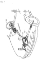
- FIG. 1 is an overall perspective view of a steering device 101 installed in a vehicle according to an embodiment of the present invention.
- the steering device 101 axially rotatably supports a steering shaft 102.
- the steering shaft 102 is attached, at an upper end thereof (an end toward the vehicle rear), with a steering wheel 103 and connected, at a lower end thereof (an end toward the vehicle front), with an intermediate shaft 105 via a universal joint 104.
- the intermediate shaft 105 is connected, at a lower end thereof, with a universal joint 106 which is connected with a steering gear 107 including a rack and pinion mechanism.
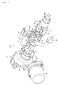
- FIG. 2 is a perspective view, as seen from above on the left side toward the vehicle rear, of an essential part of the steering device 101 according to the present embodiment of the present invention.
- FIG. 3 is a perspective view, as seen from above on the right side toward the vehicle rear, of the steering device 101 of the present embodiment with a mounting bracket for mounting to the vehicle body removed.
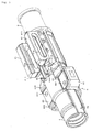
- FIG. 4 is a perspective view, as seen from above on the right side toward the vehicle rear, of the steering device 101 in a state before a steering lock device is attached to the column assembly thereof.
- FIG. 5 is a perspective view, as seen from above on the right side toward the vehicle rear, of the column assembly alone shown in FIG. 4 .
- FIG. 6 is en enlarged plan view of a portion around the flange sections of the column assembly.
- FIG. 7 is a perspective view, as seen from below on the right side toward the vehicle rear, of the column assembly shown in FIG. 4 .
- FIG. 8 is an enlarged perspective view, as seen from below on the right side toward the vehicle rear, of a portion around the flange section shown in FIG. 7 of the column assembly.
- FIG. 9 is a front view, as seen from the right side in the vehicle width direction, of the column assembly shown in FIG. 4 .
- FIG. 10 is an enlarged front view, as seen from the right side in the vehicle width direction, of a portion around the flange section shown in FIG. 9 of the column assembly.
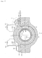
- FIG. 11 is a cross-sectional view taken along line A-A in FIG. 10 .
- FIG. 12 is a cross-sectional view, including the steering lock device attached to the column assembly, taken along line A-A in FIG. 10 .
- FIG. 13 is a cross-sectional view, including the steering lock device attached to the column assembly, taken along line B-B in FIG. 10 .
- FIG. 14 is a cross-sectional view, including the steering lock device attached to the column assembly, taken along line C-C in FIG. 10 .
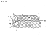
- FIG. 15 is an enlarged cross-sectional view of portion P shown in FIG. 13 .
- the steering device 101 of the present embodiment of the present invention includes a mounting bracket 2 for mounting to the vehicle body, an inner column (lower column) 3, and an outer column (upper column) 4.
- the mounting bracket 2 is fixed, via capsules 23, to the vehicle body, not shown.
- the cylindrical inner column 3 is fitted, at an outer peripheral portion thereof toward the vehicle rear (toward the right side as seen in FIG. 2 ), with the inner peripheral surface of the hollow cylindrical outer column 4 such that the outer column 4 is telescopically movable (in parallel with the center axis of the inner column 3).
- the outer column 4 is made of a cast aluminum alloy formed, for example, by die casting.
- the outer column 4 axially rotatably supports an upper steering shaft 102A. An end portion toward the vehicle rear of the upper steering shaft 102A is fixed with the steering wheel 103 (see FIG. 1 ).
- the inner column 3 is attached, at a portion thereof toward the vehicle front, with an assist device (steering assisting part) 5 for providing an auxiliary torque.
- the assist device 5 includes a gear housing 51 to which an electric motor 52 is fixed. A worm wheel inside the gear housing 51 engages a worm coupled to the rotary shaft, not shown, of the electric motor 52.
- the direction and magnitude of the torque applied from the steering wheel 103 to the upper steering shaft 102A is detected by a torque sensor.
- the electric motor 52 is driven according to the torque direction and magnitude detected by the torque sensor so as to generate, via a deceleration mechanism including a worm and a worm wheel, an auxiliary torque of a proper direction and magnitude.
- the outer column 4 is provided, in an upper portion thereof toward the vehicle top, with clamp members 41 formed to project toward the vehicle top on both the left and right sides in the vehicle width direction. As shown in FIGS. 2 to 15 , outer sides 411 of the clamp members 41 are held, to be slidingly tiltable and telescopically slidable, between left and right side plates 24 of the mounting bracket 2.
- the clamp members 41 each have a long telescopic adjustment slot 412 extending in the axial direction of the outer column 4.
- the left and right side plates 24 of the mounting brackets 2 each have a long tilt adjusting slot 25 extending in the vehicle height direction.
- a round clamping rod 21 is inserted through the long tilt adjusting slots 25 and long telescopic adjustment slots 412.
- a cam lock mechanism 26 is actuated to cause the left and right side plates 24 of the mounting bracket 2 to be clamped.
- the left and right clamp members 41 attached to the outer column 4 are strongly clamped by the left and right side plates 24 of the mounting bracket 2.
- the outer column 4 has, on an upper side thereof toward the vehicle top, a slit 42 formed through the thickness between the outer periphery and inner periphery thereof.
- the slit 42 is a long slit extending, in the axial direction of the outer column 4, between the clamp members 41.
- the hollow cylindrical outer column 4 has a pair of flange sections 43 and 44 formed integrally therewith on the left and right sides, in the vehicle width direction, toward the vehicle rear.
- the flange sections 43 and 44 are correspondingly positioned on the outer periphery of the outer column 4 and project radially outwardly, respectively.
- the flange sections 43 and 44 have bolt holes 431 and 441, respectively.
- the volt hole 431 is formed in a portion near the end toward the vehicle front (rightward as seen in FIGS. 3 and 6 ) of the left flange section 43 as seen from the vehicle rear side
- the volt hole 441 is formed in a portion near the end toward the vehicle rear (leftward as seen in FIGS. 3 and 6 ) of the right flange section 44 as seen from the vehicle rear side.
- the left flange section 43 is provided with flange-like ribs 432 and 433 formed integrally therewith.
- the ribs 432 and 433 reinforce the flange section 43 by connecting the flange section 43 to the outer periphery of the outer column 4.
- the rib 432 is formed on a side toward the vehicle rear (leftward as seen in FIGS. 3 and 6 ) of the left flange section 43
- the rib 433 is formed on a side toward the vehicle front (rightward as seen in FIGS. 3 and 6 ) of the left flange section 43.
- the right flange section 44 is provided with flange-like ribs 442 and 443 formed integrally therewith.
- the ribs 442 and 443 reinforce the flange section 44 by connecting the flange section 44 to the outer periphery of the outer column 4.
- the rib 442 is formed on a side toward the vehicle front (rightward as seen in FIGS. 3 and 6 ) of the right flange section 44, and the rib 443 is formed, integrally with the rib 442, on a side toward the vehicle front of the rib 442.
- the ribs 432, 433, 442 and 443 are formed such that their thickness in a direction perpendicular to the axial direction of the outer column 4 increases toward the center axis of the outer column 4.
- the ribs 433 and 443 each extend to a vicinity of a closed end 421 toward the vehicle rear of the slit 42 thereby reinforcing the strength of the closed end 421 of the slit 42 where stress concentrates when the outer column 4 is telescopically clamped.
- the outer column 4 is also provided with thin parts 434 and 444 formed on the outer periphery thereof to be outside, in the vehicle width direction, a parallel portion 422 of the slit 42 and close to where the parallel portion 422 and the closed end 421 meet.
- the thin parts 434 and 444 allow the slit width of the parallel portion 422 to be reduced by a small force when the outer column 4 is telescopically clamped. Namely, they make it easier to strongly clamp the outer periphery of the inner column 3 so as to intensify telescopic clamping.
- a housing 61 of the steering lock device 6 is attached to mounting surfaces 435 and 445 provided on an underside of the flange section 43 and ribs 432 and 433 and on an underside of the flange section 44 and ribs 442 and 443, respectively.
- the mounting surfaces 435 and 445 extend in parallel along the axial direction of the outer column 4.
- the housing 61 is made of an aluminum alloy and has, on an upper side thereof, a circular concave surface 62.
- Flat clamping surfaces 63 are formed at both ends in the vehicle width direction of the circular concave surface 62.
- the clamping surfaces 63 have female threads 64 formed therein to correspond, respectively, to the bolt holes 431 and 441 formed in the flange sections 43 and 44.
- an elliptical lock pin 66 projects from an elliptical engaging convex part 65 formed on a right side of the circular concave surface 62.
- the engaging convex part 65 is formed to project from the circular concave surface 62 toward the outer periphery of the outer column 4.
- the upper steering shaft 102A is fitted with a key lock collar 67 press-fitted to the outer periphery thereof.
- a leading end portion of the lock pin 66 projected from the engaging convex part 65 engages a key lock hole 671 formed in the key lock collar 67 thereby locking the steering wheel 103 not to allow it to rotate.
- the outer column 4 has an elliptical through hole 45 formed in a right side thereof.
- the elliptical through hole 45 is sized such that, when the lock pin 66 is inserted therein, a slight gap is formed between the through hole 45 and the outer periphery of the lock pin 66.
- the through hole 45 is formed to be circumferentially spaced 90 degrees from the slit 42 of the outer column 4.
- the outer column 4 also has a bottomed guide groove 46 formed on a right side thereof.
- the guide groove 46 extends, in the axial direction of the outer column 4, from near the elliptical through hole 45 to the end toward the vehicle rear (the left end as seen in FIG. 4 ) of the outer column 4.
- the width (groove width) W1 in the vehicle height direction of the guide groove 46 (see FIG. 12 ) is slightly larger than the width W2 in the vehicle height direction of the engaging convex part 65 of the steering lock device 6.
- the guide groove 46 has a closed end 462 (see FIG. 4 ) closer to the vehicle front than the elliptical through hole 45 and is open ended at the end toward the vehicle rear of the outer column 4.
- the engaging convex part 65 has a circular concave surface (to oppose a bottom surface 461 of the guide groove 46) 651 formed on a leading end portion thereof.
- the outer diameter R1 (see FIG. 12 ) of the bottom surface 461 of the guide groove 46 is slightly smaller than the inner diameter R2 of the circular concave surface 651.
- the steering lock device 6 is assembled to the outer column 4 by inserting the engaging convex part 65 of the steering lock device 6 from the vehicle rear side into the guide groove 46, then sliding the steering lock device 6 along the guide groove 46 toward the vehicle front.
- the female threads 64 formed in the housing 61 of the steering lock device 6 are positioned to correspond to the bolt holes 431 and 441 formed in the flange sections 43 and 44.
- the lock pin 66 of the steering lock device 6 is positioned to correspond to the key lock hole 671 formed in the key lock collar 67.
- bolts 68 are screwed, through the bolt holes 431 and 441, in the female threads 64 and tightened to assemble the housing 61 to the outer column 4.
- the clamping force is born by the flange section 43 and ribs 432 and 433 and also by the flange section 44 and ribs 442 and 443 without any force applied to the through hole 45.
- the engaging convex part 65 is not fitted in the through hole 45, so that the through hole 45 is only required to be large enough to allow the lock pin 66 whose cross-sectional area is smaller than that of the engaging convex part 65 to come in and out. This makes it possible to reduce the cross-sectional area of the through hole 45 and thereby increase the strength of the outer column 4.
- the mounting surface 445 of the right flange section 44 has concave relief portions 47 and 48 formed near the bolt hole 441.
- the relief portions 47 and 48 are concave by ⁇ 3 (see FIGS. 13 and 15 ) from the mount ing surface 445.
- the relief portion 47 is formed on the vehicle rear side (left side as seen in FIG. 8 ) of the bolt hole 441 and the relief portion 48 is formed on the vehicle front side (right side as seen in FIG. 8 ) of the bolt hole 441.
- the relief portions 47 and 48 are formed to extend from an outer side 446, in the vehicle width direction, of the flange section 44 to a base portion (where the flange section 44 and the outer periphery of the outer column 4 meet) of the flange section 44.
- the relief portions 47 and 48 have round corners 471 and 481 formed where the relief portions 47 and 48 meet the outer periphery of the outer column 4, respectively.
- radius R1 (see FIG. 15 ) of each of the round corners 471 and 481 of the relief portions 47 and 48 can be made larger than radius R2 of a round corner 447 of the mounting surface 445. This makes it possible to avoid interference between the relief portions 47 and 48 and the corner 631 at an inner end, in the vehicle width direction, of the right clamping surface 63 of the steering lock device 6.
- the flange section 44 and ribs 442 and 443 are formed between the through hole 45 through which the lock pin 66 is moved in and out and the slit 42 for contracting the inner peripheral diameter of the outer column 4, so that strength of the outer column 4 is increased.
- both the strength of the outer column 4 against the bending moment applied to the lock pin 66 in a key-locked state and the strength of the outer column 4 against telescopic clamping effected by contracting the inner peripheral diameter of the outer column 4 can be secured.
- the relief portions 47 and 48 are formed near the bolt hole 441 formed in the mounting surface 445 of the right flange section 44, such relief portions may be formed near the bolt hole 431 formed in the mounting surface 435 of the left flange section 43. Such relief portions may even be formed both near the bolt hole 441 and near the bolt hole 431.
- the outer column is made of an aluminum alloy, it may be made of a magnesium alloy or a resin.
Landscapes
- Engineering & Computer Science (AREA)
- Mechanical Engineering (AREA)
- Steering Controls (AREA)
Applications Claiming Priority (2)
| Application Number | Priority Date | Filing Date | Title |
|---|---|---|---|
| JP2010184973A JP5429109B2 (ja) | 2010-08-20 | 2010-08-20 | ステアリング装置 |
| PCT/JP2011/065941 WO2012023366A1 (ja) | 2010-08-20 | 2011-07-13 | ステアリング装置 |
Publications (3)
| Publication Number | Publication Date |
|---|---|
| EP2607201A1 EP2607201A1 (en) | 2013-06-26 |
| EP2607201A4 EP2607201A4 (en) | 2014-07-23 |
| EP2607201B1 true EP2607201B1 (en) | 2015-09-09 |
Family
ID=45605027
Family Applications (1)
| Application Number | Title | Priority Date | Filing Date |
|---|---|---|---|
| EP11790843.4A Active EP2607201B1 (en) | 2010-08-20 | 2011-07-13 | Steering device |
Country Status (5)
| Country | Link |
|---|---|
| US (1) | US8869646B2 (ja) |
| EP (1) | EP2607201B1 (ja) |
| JP (1) | JP5429109B2 (ja) |
| CN (1) | CN102448794B (ja) |
| WO (1) | WO2012023366A1 (ja) |
Families Citing this family (8)
| Publication number | Priority date | Publication date | Assignee | Title |
|---|---|---|---|---|
| US20110088501A1 (en) * | 2009-10-20 | 2011-04-21 | Mando Corporation | Steering column for vehicle |
| JP5299435B2 (ja) * | 2010-04-12 | 2013-09-25 | 日本精工株式会社 | ステアリング装置 |
| CN104245438B (zh) * | 2013-04-18 | 2016-07-06 | 日本精工株式会社 | 转向锁装置 |
| CN105813919B (zh) * | 2014-03-03 | 2018-02-06 | 日本精工株式会社 | 伸缩转向装置用外柱和伸缩转向装置 |
| JP6497543B2 (ja) * | 2015-01-22 | 2019-04-10 | 株式会社ジェイテクト | ステアリング装置 |
| KR102487792B1 (ko) * | 2016-02-05 | 2023-01-13 | 에이치엘만도 주식회사 | 스티어링 시스템용 기어박스의 마운팅부시 |
| CN113015669B (zh) * | 2018-11-15 | 2023-06-06 | 日本精工株式会社 | 外柱以及转向装置 |
| JP7484323B2 (ja) * | 2020-03-30 | 2024-05-16 | 日本精工株式会社 | ステアリング装置 |
Family Cites Families (31)
| Publication number | Priority date | Publication date | Assignee | Title |
|---|---|---|---|---|
| JPS58181657U (ja) * | 1982-05-31 | 1983-12-03 | いすゞ自動車株式会社 | テレスコピツクステアリングのハンドルロツク機構 |
| US5090730A (en) * | 1991-01-23 | 1992-02-25 | Itt Corporation | Vehicle steering column apparatus |
| DE19707067C1 (de) * | 1997-02-22 | 1998-06-25 | Kostal Leopold Gmbh & Co Kg | Lenksäuleneinheit für einen Kraftwagen |
| US6659504B2 (en) * | 2001-05-18 | 2003-12-09 | Delphi Technologies, Inc. | Steering column for a vehicle |
| JP2002337663A (ja) | 2001-05-22 | 2002-11-27 | Fuji Heavy Ind Ltd | ステアリングロックの取付構造 |
| JP3738200B2 (ja) * | 2001-06-27 | 2006-01-25 | 光洋精工株式会社 | 衝撃吸収ステアリング装置 |
| AU2003252642A1 (en) * | 2002-07-17 | 2004-02-02 | Nsk Ltd. | Steering column device |
| ATE439289T1 (de) * | 2002-10-04 | 2009-08-15 | Nsk Ltd | Lenkstulenvorrichtung |
| JP2004314941A (ja) * | 2003-03-31 | 2004-11-11 | Fuji Kiko Co Ltd | 衝撃吸収式ステアリング装置 |
| US7093855B2 (en) * | 2003-12-05 | 2006-08-22 | Delphi Technologies, Inc. | Steering column assembly having clamping mechanism |
| US7178422B2 (en) * | 2004-07-02 | 2007-02-20 | Delphi Technologies, Inc. | Electrical tilt and telescope locking mechanism |
| JP2006111124A (ja) * | 2004-10-14 | 2006-04-27 | Mazda Motor Corp | ステアリングロック装置 |
| US7367589B2 (en) * | 2005-07-15 | 2008-05-06 | Chrysler Llc | Collapsible steering assembly with a stationary reaction surface |
| JP2007196784A (ja) * | 2006-01-25 | 2007-08-09 | Toyota Motor Corp | ステアリングホイールロック装置 |
| JP2007331530A (ja) * | 2006-06-14 | 2007-12-27 | Tokai Rika Co Ltd | ステアリングロック装置 |
| US7730804B2 (en) * | 2007-03-21 | 2010-06-08 | Gm Global Technology Operations, Inc. | Central lock device of an adjustable steering column assembly |
| US7635149B2 (en) * | 2007-03-21 | 2009-12-22 | Gm Global Technology Operations, Inc. | Rocker-arm lock device of an adjustable steering column assembly |
| US8047096B2 (en) * | 2007-03-30 | 2011-11-01 | Nexteer (Beijing) Technology Co., Ltd. | Lock mechanism for an adjustable steering column assembly |
| JP5358932B2 (ja) * | 2007-11-13 | 2013-12-04 | 日本精工株式会社 | ステアリング装置 |
| GB0723485D0 (en) * | 2007-11-30 | 2008-01-09 | Trw Das A S | Adjustable steering column assembly |
| JP2009196562A (ja) * | 2008-02-22 | 2009-09-03 | Nsk Ltd | ステアリングロック装置付伸縮式ステアリング装置 |
| EP2497696B1 (en) * | 2010-08-05 | 2015-02-18 | NSK Ltd. | Shock-absorbing steering device |
| CN102596689B (zh) * | 2010-11-02 | 2014-03-12 | 日本精工株式会社 | 转向柱用支承装置 |
| WO2012086331A1 (ja) * | 2010-12-21 | 2012-06-28 | 日本精工株式会社 | ステアリングコラム用支持装置 |
| US8544887B2 (en) * | 2010-12-28 | 2013-10-01 | Nsk Ltd. | Steering column support apparatus and assembly method |
| WO2012128171A1 (ja) * | 2011-03-18 | 2012-09-27 | 日本精工株式会社 | ステアリング装置 |
| US8596683B2 (en) * | 2011-04-14 | 2013-12-03 | Nsk Ltd. | Steering apparatus |
| JP5382066B2 (ja) * | 2011-06-03 | 2014-01-08 | 日本精工株式会社 | ステアリング装置 |
| JP2013001242A (ja) * | 2011-06-16 | 2013-01-07 | Jtekt Corp | ステアリング装置 |
| JP5789500B2 (ja) * | 2011-11-29 | 2015-10-07 | 富士機工株式会社 | ステアリングコラム装置 |
| JP2014058200A (ja) * | 2012-09-14 | 2014-04-03 | Yamada Seisakusho Co Ltd | ステアリング装置 |
-
2010
- 2010-08-20 JP JP2010184973A patent/JP5429109B2/ja active Active
-
2011
- 2011-07-13 CN CN201180001069.0A patent/CN102448794B/zh active Active
- 2011-07-13 US US13/376,975 patent/US8869646B2/en not_active Expired - Fee Related
- 2011-07-13 EP EP11790843.4A patent/EP2607201B1/en active Active
- 2011-07-13 WO PCT/JP2011/065941 patent/WO2012023366A1/ja active Application Filing
Also Published As
| Publication number | Publication date |
|---|---|
| EP2607201A4 (en) | 2014-07-23 |
| JP2012040984A (ja) | 2012-03-01 |
| US8869646B2 (en) | 2014-10-28 |
| JP5429109B2 (ja) | 2014-02-26 |
| WO2012023366A1 (ja) | 2012-02-23 |
| US20120291584A1 (en) | 2012-11-22 |
| EP2607201A1 (en) | 2013-06-26 |
| CN102448794A (zh) | 2012-05-09 |
| CN102448794B (zh) | 2014-03-12 |
Similar Documents
| Publication | Publication Date | Title |
|---|---|---|
| EP2607202B1 (en) | Steering device | |
| EP2607201B1 (en) | Steering device | |
| EP2535239B1 (en) | Steering apparatus | |
| JP5076963B2 (ja) | ステアリング装置 | |
| EP3260350B1 (en) | Steering apparatus | |
| EP3705375B1 (en) | Gear housing for electric power steering device, manufacturing method thereof, and electric power steering device | |
| JP5195825B2 (ja) | 車両用ステアリング装置 | |
| JP5146474B2 (ja) | ステアリングコラム装置とその組立方法 | |
| EP2607184B1 (en) | Steering device | |
| JP5970992B2 (ja) | 電動パワーステアリング装置 | |
| EP3075635B1 (en) | Steering apparatus | |
| JP6313997B2 (ja) | ステアリング装置 | |
| JP2015051655A (ja) | ステアリング装置 | |
| US8955882B2 (en) | Steering apparatus | |
| JP5970991B2 (ja) | 電動パワーステアリング装置 | |
| JP5970989B2 (ja) | 電動パワーステアリング装置 | |
| JP5966700B2 (ja) | 電動パワーステアリング装置 | |
| JP5212398B2 (ja) | ステアリング装置 | |
| JP4178318B2 (ja) | 操舵装置 | |
| JP2014234003A (ja) | ステアリングコラム装置 | |
| JP2015229394A (ja) | ステアリングコラム装置 | |
| JP2016203700A (ja) | ステアリング装置用取付け装置 | |
| JP2017128290A (ja) | 電動パワーステアリング装置 |
Legal Events
| Date | Code | Title | Description |
|---|---|---|---|
| PUAI | Public reference made under article 153(3) epc to a published international application that has entered the european phase |
Free format text: ORIGINAL CODE: 0009012 |
|
| 17P | Request for examination filed |
Effective date: 20111213 |
|
| AK | Designated contracting states |
Kind code of ref document: A1 Designated state(s): AL AT BE BG CH CY CZ DE DK EE ES FI FR GB GR HR HU IE IS IT LI LT LU LV MC MK MT NL NO PL PT RO RS SE SI SK SM TR |
|
| DAX | Request for extension of the european patent (deleted) | ||
| A4 | Supplementary search report drawn up and despatched |
Effective date: 20140625 |
|
| RIC1 | Information provided on ipc code assigned before grant |
Ipc: B62D 1/16 20060101ALI20140618BHEP Ipc: B60R 25/02 20130101AFI20140618BHEP |
|
| REG | Reference to a national code |
Ref country code: DE Ref legal event code: R079 Ref document number: 602011019669 Country of ref document: DE Free format text: PREVIOUS MAIN CLASS: B62D0001160000 Ipc: B60R0025020000 |
|
| RIC1 | Information provided on ipc code assigned before grant |
Ipc: B62D 1/16 20060101ALI20150313BHEP Ipc: B60R 25/02 20130101AFI20150313BHEP |
|
| GRAP | Despatch of communication of intention to grant a patent |
Free format text: ORIGINAL CODE: EPIDOSNIGR1 |
|
| INTG | Intention to grant announced |
Effective date: 20150429 |
|
| GRAS | Grant fee paid |
Free format text: ORIGINAL CODE: EPIDOSNIGR3 |
|
| GRAA | (expected) grant |
Free format text: ORIGINAL CODE: 0009210 |
|
| AK | Designated contracting states |
Kind code of ref document: B1 Designated state(s): AL AT BE BG CH CY CZ DE DK EE ES FI FR GB GR HR HU IE IS IT LI LT LU LV MC MK MT NL NO PL PT RO RS SE SI SK SM TR |
|
| REG | Reference to a national code |
Ref country code: GB Ref legal event code: FG4D |
|
| REG | Reference to a national code |
Ref country code: AT Ref legal event code: REF Ref document number: 747851 Country of ref document: AT Kind code of ref document: T Effective date: 20150915 Ref country code: CH Ref legal event code: EP |
|
| REG | Reference to a national code |
Ref country code: IE Ref legal event code: FG4D |
|
| REG | Reference to a national code |
Ref country code: DE Ref legal event code: R096 Ref document number: 602011019669 Country of ref document: DE |
|
| REG | Reference to a national code |
Ref country code: NL Ref legal event code: MP Effective date: 20150909 |
|
| PG25 | Lapsed in a contracting state [announced via postgrant information from national office to epo] |
Ref country code: LT Free format text: LAPSE BECAUSE OF FAILURE TO SUBMIT A TRANSLATION OF THE DESCRIPTION OR TO PAY THE FEE WITHIN THE PRESCRIBED TIME-LIMIT Effective date: 20150909 Ref country code: NO Free format text: LAPSE BECAUSE OF FAILURE TO SUBMIT A TRANSLATION OF THE DESCRIPTION OR TO PAY THE FEE WITHIN THE PRESCRIBED TIME-LIMIT Effective date: 20151209 Ref country code: GR Free format text: LAPSE BECAUSE OF FAILURE TO SUBMIT A TRANSLATION OF THE DESCRIPTION OR TO PAY THE FEE WITHIN THE PRESCRIBED TIME-LIMIT Effective date: 20151210 Ref country code: FI Free format text: LAPSE BECAUSE OF FAILURE TO SUBMIT A TRANSLATION OF THE DESCRIPTION OR TO PAY THE FEE WITHIN THE PRESCRIBED TIME-LIMIT Effective date: 20150909 Ref country code: LV Free format text: LAPSE BECAUSE OF FAILURE TO SUBMIT A TRANSLATION OF THE DESCRIPTION OR TO PAY THE FEE WITHIN THE PRESCRIBED TIME-LIMIT Effective date: 20150909 |
|
| REG | Reference to a national code |
Ref country code: LT Ref legal event code: MG4D |
|
| REG | Reference to a national code |
Ref country code: AT Ref legal event code: MK05 Ref document number: 747851 Country of ref document: AT Kind code of ref document: T Effective date: 20150909 |
|
| PG25 | Lapsed in a contracting state [announced via postgrant information from national office to epo] |
Ref country code: ES Free format text: LAPSE BECAUSE OF FAILURE TO SUBMIT A TRANSLATION OF THE DESCRIPTION OR TO PAY THE FEE WITHIN THE PRESCRIBED TIME-LIMIT Effective date: 20150909 Ref country code: HR Free format text: LAPSE BECAUSE OF FAILURE TO SUBMIT A TRANSLATION OF THE DESCRIPTION OR TO PAY THE FEE WITHIN THE PRESCRIBED TIME-LIMIT Effective date: 20150909 Ref country code: RS Free format text: LAPSE BECAUSE OF FAILURE TO SUBMIT A TRANSLATION OF THE DESCRIPTION OR TO PAY THE FEE WITHIN THE PRESCRIBED TIME-LIMIT Effective date: 20150909 Ref country code: SE Free format text: LAPSE BECAUSE OF FAILURE TO SUBMIT A TRANSLATION OF THE DESCRIPTION OR TO PAY THE FEE WITHIN THE PRESCRIBED TIME-LIMIT Effective date: 20150909 |
|
| PG25 | Lapsed in a contracting state [announced via postgrant information from national office to epo] |
Ref country code: NL Free format text: LAPSE BECAUSE OF FAILURE TO SUBMIT A TRANSLATION OF THE DESCRIPTION OR TO PAY THE FEE WITHIN THE PRESCRIBED TIME-LIMIT Effective date: 20150909 |
|
| PG25 | Lapsed in a contracting state [announced via postgrant information from national office to epo] |
Ref country code: IS Free format text: LAPSE BECAUSE OF FAILURE TO SUBMIT A TRANSLATION OF THE DESCRIPTION OR TO PAY THE FEE WITHIN THE PRESCRIBED TIME-LIMIT Effective date: 20160109 Ref country code: SK Free format text: LAPSE BECAUSE OF FAILURE TO SUBMIT A TRANSLATION OF THE DESCRIPTION OR TO PAY THE FEE WITHIN THE PRESCRIBED TIME-LIMIT Effective date: 20150909 Ref country code: IT Free format text: LAPSE BECAUSE OF FAILURE TO SUBMIT A TRANSLATION OF THE DESCRIPTION OR TO PAY THE FEE WITHIN THE PRESCRIBED TIME-LIMIT Effective date: 20150909 Ref country code: CZ Free format text: LAPSE BECAUSE OF FAILURE TO SUBMIT A TRANSLATION OF THE DESCRIPTION OR TO PAY THE FEE WITHIN THE PRESCRIBED TIME-LIMIT Effective date: 20150909 Ref country code: EE Free format text: LAPSE BECAUSE OF FAILURE TO SUBMIT A TRANSLATION OF THE DESCRIPTION OR TO PAY THE FEE WITHIN THE PRESCRIBED TIME-LIMIT Effective date: 20150909 |
|
| PG25 | Lapsed in a contracting state [announced via postgrant information from national office to epo] |
Ref country code: PT Free format text: LAPSE BECAUSE OF FAILURE TO SUBMIT A TRANSLATION OF THE DESCRIPTION OR TO PAY THE FEE WITHIN THE PRESCRIBED TIME-LIMIT Effective date: 20160111 Ref country code: AT Free format text: LAPSE BECAUSE OF FAILURE TO SUBMIT A TRANSLATION OF THE DESCRIPTION OR TO PAY THE FEE WITHIN THE PRESCRIBED TIME-LIMIT Effective date: 20150909 Ref country code: PL Free format text: LAPSE BECAUSE OF FAILURE TO SUBMIT A TRANSLATION OF THE DESCRIPTION OR TO PAY THE FEE WITHIN THE PRESCRIBED TIME-LIMIT Effective date: 20150909 Ref country code: RO Free format text: LAPSE BECAUSE OF FAILURE TO SUBMIT A TRANSLATION OF THE DESCRIPTION OR TO PAY THE FEE WITHIN THE PRESCRIBED TIME-LIMIT Effective date: 20150909 |
|
| REG | Reference to a national code |
Ref country code: DE Ref legal event code: R097 Ref document number: 602011019669 Country of ref document: DE |
|
| REG | Reference to a national code |
Ref country code: FR Ref legal event code: PLFP Year of fee payment: 6 |
|
| PLBE | No opposition filed within time limit |
Free format text: ORIGINAL CODE: 0009261 |
|
| STAA | Information on the status of an ep patent application or granted ep patent |
Free format text: STATUS: NO OPPOSITION FILED WITHIN TIME LIMIT |
|
| 26N | No opposition filed |
Effective date: 20160610 |
|
| PG25 | Lapsed in a contracting state [announced via postgrant information from national office to epo] |
Ref country code: DK Free format text: LAPSE BECAUSE OF FAILURE TO SUBMIT A TRANSLATION OF THE DESCRIPTION OR TO PAY THE FEE WITHIN THE PRESCRIBED TIME-LIMIT Effective date: 20150909 Ref country code: SI Free format text: LAPSE BECAUSE OF FAILURE TO SUBMIT A TRANSLATION OF THE DESCRIPTION OR TO PAY THE FEE WITHIN THE PRESCRIBED TIME-LIMIT Effective date: 20150909 |
|
| PG25 | Lapsed in a contracting state [announced via postgrant information from national office to epo] |
Ref country code: BE Free format text: LAPSE BECAUSE OF FAILURE TO SUBMIT A TRANSLATION OF THE DESCRIPTION OR TO PAY THE FEE WITHIN THE PRESCRIBED TIME-LIMIT Effective date: 20150909 |
|
| REG | Reference to a national code |
Ref country code: CH Ref legal event code: PL |
|
| PG25 | Lapsed in a contracting state [announced via postgrant information from national office to epo] |
Ref country code: MC Free format text: LAPSE BECAUSE OF FAILURE TO SUBMIT A TRANSLATION OF THE DESCRIPTION OR TO PAY THE FEE WITHIN THE PRESCRIBED TIME-LIMIT Effective date: 20150909 |
|
| PG25 | Lapsed in a contracting state [announced via postgrant information from national office to epo] |
Ref country code: CH Free format text: LAPSE BECAUSE OF NON-PAYMENT OF DUE FEES Effective date: 20160731 Ref country code: LI Free format text: LAPSE BECAUSE OF NON-PAYMENT OF DUE FEES Effective date: 20160731 |
|
| REG | Reference to a national code |
Ref country code: IE Ref legal event code: MM4A |
|
| REG | Reference to a national code |
Ref country code: FR Ref legal event code: PLFP Year of fee payment: 7 |
|
| PG25 | Lapsed in a contracting state [announced via postgrant information from national office to epo] |
Ref country code: IE Free format text: LAPSE BECAUSE OF NON-PAYMENT OF DUE FEES Effective date: 20160713 |
|
| PG25 | Lapsed in a contracting state [announced via postgrant information from national office to epo] |
Ref country code: LU Free format text: LAPSE BECAUSE OF NON-PAYMENT OF DUE FEES Effective date: 20160713 |
|
| PG25 | Lapsed in a contracting state [announced via postgrant information from national office to epo] |
Ref country code: CY Free format text: LAPSE BECAUSE OF FAILURE TO SUBMIT A TRANSLATION OF THE DESCRIPTION OR TO PAY THE FEE WITHIN THE PRESCRIBED TIME-LIMIT Effective date: 20150909 Ref country code: SM Free format text: LAPSE BECAUSE OF FAILURE TO SUBMIT A TRANSLATION OF THE DESCRIPTION OR TO PAY THE FEE WITHIN THE PRESCRIBED TIME-LIMIT Effective date: 20150909 Ref country code: HU Free format text: LAPSE BECAUSE OF FAILURE TO SUBMIT A TRANSLATION OF THE DESCRIPTION OR TO PAY THE FEE WITHIN THE PRESCRIBED TIME-LIMIT; INVALID AB INITIO Effective date: 20110713 |
|
| REG | Reference to a national code |
Ref country code: FR Ref legal event code: PLFP Year of fee payment: 8 |
|
| PG25 | Lapsed in a contracting state [announced via postgrant information from national office to epo] |
Ref country code: MT Free format text: LAPSE BECAUSE OF NON-PAYMENT OF DUE FEES Effective date: 20160731 Ref country code: MK Free format text: LAPSE BECAUSE OF FAILURE TO SUBMIT A TRANSLATION OF THE DESCRIPTION OR TO PAY THE FEE WITHIN THE PRESCRIBED TIME-LIMIT Effective date: 20150909 Ref country code: TR Free format text: LAPSE BECAUSE OF FAILURE TO SUBMIT A TRANSLATION OF THE DESCRIPTION OR TO PAY THE FEE WITHIN THE PRESCRIBED TIME-LIMIT Effective date: 20150909 |
|
| PG25 | Lapsed in a contracting state [announced via postgrant information from national office to epo] |
Ref country code: BG Free format text: LAPSE BECAUSE OF FAILURE TO SUBMIT A TRANSLATION OF THE DESCRIPTION OR TO PAY THE FEE WITHIN THE PRESCRIBED TIME-LIMIT Effective date: 20150909 |
|
| PG25 | Lapsed in a contracting state [announced via postgrant information from national office to epo] |
Ref country code: AL Free format text: LAPSE BECAUSE OF FAILURE TO SUBMIT A TRANSLATION OF THE DESCRIPTION OR TO PAY THE FEE WITHIN THE PRESCRIBED TIME-LIMIT Effective date: 20150909 |
|
| PGFP | Annual fee paid to national office [announced via postgrant information from national office to epo] |
Ref country code: FR Payment date: 20190619 Year of fee payment: 9 |
|
| PGFP | Annual fee paid to national office [announced via postgrant information from national office to epo] |
Ref country code: GB Payment date: 20190710 Year of fee payment: 9 |
|
| GBPC | Gb: european patent ceased through non-payment of renewal fee |
Effective date: 20200713 |
|
| PG25 | Lapsed in a contracting state [announced via postgrant information from national office to epo] |
Ref country code: GB Free format text: LAPSE BECAUSE OF NON-PAYMENT OF DUE FEES Effective date: 20200713 Ref country code: FR Free format text: LAPSE BECAUSE OF NON-PAYMENT OF DUE FEES Effective date: 20200731 |
|
| PGFP | Annual fee paid to national office [announced via postgrant information from national office to epo] |
Ref country code: DE Payment date: 20230531 Year of fee payment: 13 |