WO2012020690A1 - 平板状ケーブル用コネクタ - Google Patents
平板状ケーブル用コネクタ Download PDFInfo
- Publication number
- WO2012020690A1 WO2012020690A1 PCT/JP2011/067856 JP2011067856W WO2012020690A1 WO 2012020690 A1 WO2012020690 A1 WO 2012020690A1 JP 2011067856 W JP2011067856 W JP 2011067856W WO 2012020690 A1 WO2012020690 A1 WO 2012020690A1
- Authority
- WO
- WIPO (PCT)
- Prior art keywords
- flat cable
- connector
- connector housing
- housing
- holder
- Prior art date
- Legal status (The legal status is an assumption and is not a legal conclusion. Google has not performed a legal analysis and makes no representation as to the accuracy of the status listed.)
- Ceased
Links
Images








Classifications
-
- H—ELECTRICITY
- H01—ELECTRIC ELEMENTS
- H01R—ELECTRICALLY-CONDUCTIVE CONNECTIONS; STRUCTURAL ASSOCIATIONS OF A PLURALITY OF MUTUALLY-INSULATED ELECTRICAL CONNECTING ELEMENTS; COUPLING DEVICES; CURRENT COLLECTORS
- H01R13/00—Details of coupling devices of the kinds covered by groups H01R12/70 or H01R24/00 - H01R33/00
- H01R13/58—Means for relieving strain on wire connection, e.g. cord grip, for avoiding loosening of connections between wires and terminals within a coupling device terminating a cable
- H01R13/582—Means for relieving strain on wire connection, e.g. cord grip, for avoiding loosening of connections between wires and terminals within a coupling device terminating a cable the cable being clamped between assembled parts of the housing
-
- H—ELECTRICITY
- H01—ELECTRIC ELEMENTS
- H01R—ELECTRICALLY-CONDUCTIVE CONNECTIONS; STRUCTURAL ASSOCIATIONS OF A PLURALITY OF MUTUALLY-INSULATED ELECTRICAL CONNECTING ELEMENTS; COUPLING DEVICES; CURRENT COLLECTORS
- H01R13/00—Details of coupling devices of the kinds covered by groups H01R12/70 or H01R24/00 - H01R33/00
- H01R13/46—Bases; Cases
- H01R13/52—Dustproof, splashproof, drip-proof, waterproof, or flameproof cases
-
- H—ELECTRICITY
- H01—ELECTRIC ELEMENTS
- H01R—ELECTRICALLY-CONDUCTIVE CONNECTIONS; STRUCTURAL ASSOCIATIONS OF A PLURALITY OF MUTUALLY-INSULATED ELECTRICAL CONNECTING ELEMENTS; COUPLING DEVICES; CURRENT COLLECTORS
- H01R12/00—Structural associations of a plurality of mutually-insulated electrical connecting elements, specially adapted for printed circuits, e.g. printed circuit boards [PCB], flat or ribbon cables, or like generally planar structures, e.g. terminal strips, terminal blocks; Coupling devices specially adapted for printed circuits, flat or ribbon cables, or like generally planar structures; Terminals specially adapted for contact with, or insertion into, printed circuits, flat or ribbon cables, or like generally planar structures
- H01R12/70—Coupling devices
- H01R12/77—Coupling devices for flexible printed circuits, flat or ribbon cables or like structures
- H01R12/777—Coupling parts carrying pins, blades or analogous contacts
-
- H—ELECTRICITY
- H01—ELECTRIC ELEMENTS
- H01R—ELECTRICALLY-CONDUCTIVE CONNECTIONS; STRUCTURAL ASSOCIATIONS OF A PLURALITY OF MUTUALLY-INSULATED ELECTRICAL CONNECTING ELEMENTS; COUPLING DEVICES; CURRENT COLLECTORS
- H01R13/00—Details of coupling devices of the kinds covered by groups H01R12/70 or H01R24/00 - H01R33/00
- H01R13/46—Bases; Cases
- H01R13/52—Dustproof, splashproof, drip-proof, waterproof, or flameproof cases
- H01R13/5205—Sealing means between cable and housing, e.g. grommet
-
- H—ELECTRICITY
- H01—ELECTRIC ELEMENTS
- H01R—ELECTRICALLY-CONDUCTIVE CONNECTIONS; STRUCTURAL ASSOCIATIONS OF A PLURALITY OF MUTUALLY-INSULATED ELECTRICAL CONNECTING ELEMENTS; COUPLING DEVICES; CURRENT COLLECTORS
- H01R13/00—Details of coupling devices of the kinds covered by groups H01R12/70 or H01R24/00 - H01R33/00
- H01R13/58—Means for relieving strain on wire connection, e.g. cord grip, for avoiding loosening of connections between wires and terminals within a coupling device terminating a cable
- H01R13/5804—Means for relieving strain on wire connection, e.g. cord grip, for avoiding loosening of connections between wires and terminals within a coupling device terminating a cable comprising a separate cable clamping part
- H01R13/5812—Means for relieving strain on wire connection, e.g. cord grip, for avoiding loosening of connections between wires and terminals within a coupling device terminating a cable comprising a separate cable clamping part the cable clamping being achieved by mounting the separate part on the housing of the coupling device
Definitions
- the present invention relates to a flat cable connector.
- a flat cable connector As a flat cable connector, a flexible flat cable such as a flexible circuit board (FPC) or a flexible flat cable (FFC), and a connector into which an end of the flat cable is inserted and accommodated And a fork-shaped mating terminal which is accommodated in the connector and is sandwiched from the thickness direction of the flat cable and is conducted to the conductor portion of the flat cable (for example, see Patent Document 1). .
- a flexible flat cable such as a flexible circuit board (FPC) or a flexible flat cable (FFC)
- FPC flexible circuit board
- FFC flexible flat cable
- This flat cable connector is provided with a tab on the flat cable, a hook that can be displaced on the connector, and the hook is hooked on the tab when the flat cable is inserted into the connector.
- the flat cable is prevented from coming off, and the latching portion is prevented from being displaced downward to prevent the latching portion from being released from the hook.
- an object of the present invention is to provide a flat cable connector that can reliably connect a conductor portion of a flat cable and a mating terminal.
- a flat cable provided with a plurality of conductor parts, a connector housing provided with an insertion port for inserting the flat cable on one side, and sandwiched from the thickness direction of the flat cable with respect to the conductor parts And a fork-shaped mating terminal that is electrically connected to each other, wherein the flat cable is provided with a slider made of resin that covers one surface in the thickness direction of the conductor portion.
- the connector housing is provided with an accommodating portion that communicates with the insertion port, accommodates the slider, and restricts movement of the flat cable in the insertion direction into the connector housing.
- An end on the side protrudes from the housing portion toward the outside of the connector housing, and is sandwiched between the mating terminals so that the flat case is A flat cable connector in which a conductor portion of a bull and the mating terminal are connected.
- the conductor portion of the flat cable and the mating terminal can be reliably conducted.
- the connector housing is provided with an accommodating portion for accommodating the slider and restricting the movement of the flat cable in the insertion direction of the flat cable, the insertion position of the flat cable with respect to the connector housing can be positioned.
- the flat cable can be easily inserted into the connector housing.
- the flat cable is provided with the first seal member for sealing between the flat cable and the insertion port of the connector housing. Water can be prevented from entering the connector.
- the flat cable connector having the configuration (1) or (2), wherein the mating terminal is inserted from a front opening formed on the other side of the connector housing to cover the outer periphery of the housing portion.
- the connector housing is accommodated in the terminal housing portion of the mating connector, and the outer periphery of the housing portion of the connector housing is sealed between the mating connector housing and the outer periphery of the housing portion of the connector housing. 2
- Flat cable connector provided with a seal member.
- the 2nd sealing member which seals between the other party connector and the outer periphery of the accommodating part of a connector housing is provided in the outer periphery of the accommodating part of a connector housing, water penetrate
- the flat cable connector having the configuration (4), a holder for inserting and holding the flat cable through the insertion port of the connector housing and restricting the movement of the flat cable from the connector housing is assembled. Therefore, the holding of the flat cable to the connector housing can be stabilized, and the flat cable can be prevented from coming off from the connector housing, and the conduction between the conductor portion of the flat cable and the mating terminal can be stabilized.
- the flat cable connector having the configuration of (4), wherein the holder is formed in a U shape with one of both side surfaces opened, and the flat cable is formed of the holder.
- a plurality of ribs are provided symmetrically on both side surfaces of the holder, and the plurality of ribs are respectively engaged on both side surfaces of the opening end of the connector housing.
- a flat cable connector in which mating engagement grooves are provided symmetrically.
- the holder is formed in a U shape with one side opened, but the holder can be removed from the opening by engaging the rib and the engaging groove. It is possible to prevent deformation in the expanding direction.
- the ribs can be formed on either side of the open end of the connector housing while inserting the U-shaped holder through the flat cable. And the engaging groove can be engaged and assembled, and the assembling property of the holder to the connector housing can be improved.
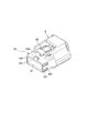
- FIG. 1 is a perspective view of a flat cable connector according to the first embodiment of the present invention.
- FIG. 2 is a cross-sectional view of the flat cable connector according to the first embodiment of the present invention.
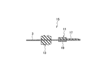
- FIG. 3 is a perspective view of the cable assembly of the flat cable connector according to the first embodiment of the present invention.
- FIG. 4 is a cross-sectional view of the cable assembly of the flat cable connector according to the first embodiment of the present invention.
- FIG. 5 is an exploded perspective view of the cable assembly of the flat cable connector according to the first embodiment of the present invention.
- FIG. 6 is a perspective view of the connector housing of the flat cable connector according to the first embodiment of the present invention.
- FIG. 7 is a cross-sectional view of the connector housing of the flat cable connector according to the first embodiment of the present invention.
- FIG. 8 is a perspective view of the mating terminal of the flat cable connector according to the first embodiment of the present invention.
- FIG. 9 is a perspective view of the mating connector of the flat cable connector according to the first embodiment of the present invention.
- FIG. 10 is a front view of the mating connector of the flat cable connector according to the first embodiment of the present invention.
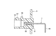
- FIG. 11 is a cross-sectional view of the mating terminal and mating connector of the flat cable connector according to the first embodiment of the present invention.
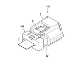
- FIG. 12 is a perspective view of a flat cable connector according to the second embodiment of the present invention.
- FIG. 13 is a sectional view of a flat cable connector according to the second embodiment of the present invention.
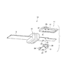
- FIG. 14 is a perspective view of a holder for a flat cable connector according to the second embodiment of the present invention.
- FIG. 15 is a front view of a holder for a flat cable connector according to the second embodiment of the present invention.
- FIG. 16 is a perspective view of the connector housing of the flat cable connector according to the second embodiment of the present invention.
- FIG. 17 is a perspective view when the flat cable connector holder according to the second embodiment of the present invention is assembled to the connector housing.
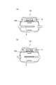
- FIG. 18 (a) is a front view when the flat cable connector holder according to the second embodiment of the present invention is assembled to the connector housing from one side.
- FIG. 18B is a front view when the holder for the flat cable connector according to the second embodiment of the present invention is assembled to the connector housing from the other side.
- FIGS. 19A and 19B are a perspective view and an enlarged view of a main part when the holder for the flat cable connector according to the second embodiment of the present invention is assembled to the connector housing.
- a flat cable connector according to an embodiment of the present invention will be described with reference to FIGS.
- the flat cable connector 1 includes a flat cable 3, a connector housing 5, a mating terminal 7, and a mating connector 9, as shown in FIGS.
- the flat cable 3 is made of a flat cable having flexibility such as FPC and FFC, and includes a plurality of conductor portions (not shown).
- a cable assembly 15 is configured by assembling a slider 11 and a sealing material 13 as a first sealing member to the flat cable 3.
- the slider 11 is made of a resin material and includes a slider body 17 and a slider cover 19.
- the slider body 17 is assembled to the upper surface of the flat cable 3 so as to cover the conductor portion of the flat cable 3.
- a plurality (two in this case) of bosses 21 project from the surface (lower surface) of the slider body 17 on the flat cable 3 side.
- the boss 21 is inserted into a boss hole 23 provided in the flat cable 3, and the slider body 17 is positioned and fixed with respect to the flat cable 3. Further, beaks 25 project from both side surfaces of the slider body 17, and the slider cover 19 is fixed.
- the slider cover 19 is assembled to the lower surface of the flat cable 3 so that a part of the conductor portion of the flat cable 3 covered with the slider body 17 is exposed to the outside. Further, the slider cover 19 is provided with a boss hole 27 through which the boss 21 of the slider body 17 protruding through the boss hole 23 of the flat cable 3 is inserted. The slider 11 is positioned and fixed with respect to the flat cable 3 by the engagement between the boss 21 and the boss holes 23 and 27. Further, locks 29 that engage with the beaks 25 of the slider body 17 are provided on both side surfaces of the slider cover 19. The slider body 17 and the slider cover 19 are fixed by the engagement between the lock 29 and the beak 25.
- the sealing material 13 is made of an elastic material such as rubber, and the flat cable 3 is inserted in close contact with the central portion.
- the sealing material 13 and the flat cable 3 may be formed as separate members and assembled, but the sealing material 13 may be integrally formed with the flat cable 3.
- the outer periphery of the sealing material 13 is elastically in close contact with the inner peripheral surface of the insertion port 31 in the insertion port 31 of the connector housing 5, and between the connector housing 5 and the flat cable 3. Seal.
- the cable assembly 15 in which the slider 11 and the sealing material 13 are assembled to such a flat cable 3 is inserted from the insertion port 31 of the connector housing 5 and assembled to the connector housing 5.
- the connector housing 5 is made of a resin material and includes an insertion port 31, a storage portion 33, a front opening 35, and a mating connector storage portion 37.
- the insertion port 31 is formed in an opening end portion 32 that opens toward one side of the connector housing 5.
- the cable assembly 15 is inserted from the insertion port 31, and the cable assembly 15 is assembled to the connector housing 5.
- the insertion port 31 accommodates the sealing material 13 of the cable assembly 15 and seals between the connector housing 5 and the flat cable 3.
- the accommodating portion 33 is provided on the inner side of the connector housing 5 with respect to the insertion port 31, and is communicated with the insertion port 31 and formed in a cylindrical shape.
- a through hole 39 is provided at the bottom of the accommodating portion 33.
- the slider 11 of the cable assembly 15 is accommodated in the accommodating portion 33, and a part of the slider 11 passes through the through hole 39 and protrudes into the mating connector accommodating portion 37.
- the protruding portion of the slider 11 becomes a connection portion 41 sandwiched between the mating terminals 7.
- the proximal end side of the connecting portion 41 of the slider 11 is brought into contact with the bottom portion of the accommodating portion 33, and the cable assembly 15 is moved in the insertion direction into the connector housing 5.
- the frontage 35 is opened toward the other side of the connector housing 5.
- the mating connector 9 is inserted from the opening 35 and the mating connector 9 is assembled to the connector housing 5.
- the front opening 35 communicates with a mating connector housing portion 37 that houses the mating connector 9.
- the mating connector housing portion 37 is provided on the outer peripheral side of the housing portion 33 inside the connector housing 5.
- the mating connector 9 inserted from the frontage 35 is housed so as to cover the outer periphery of the housing portion 33.
- the mating connector housing portion 37 is provided with a lock portion 45 of a lock arm 47 that has an operation portion 43 and a lock portion 45 and is swingably provided.
- the mating connector 9 is attached to the connector housing 5. It is fixed against.
- the connector housing 5 configured as described above is mounted on a circuit board (not shown) such as a circuit board, and conducts the flat cable 3 connected to an electronic component or the like and the mating terminal 7 connected to the circuit board. Applied for.
- the mating terminal 7 is made of a conductive metal material, is formed in an L shape, and a conduction portion 49 provided on one end side is connected to the substrate, and a sandwiching portion 51 is provided on the other end side. Is provided.
- the sandwiching part 51 has a fork shape whose tip side is opened to be elastically deformable.
- the connection portion 41 of the cable assembly 15 is sandwiched between the holding portions 51, and the conductor portion of the flat cable 3 and the mating terminal 7 are electrically connected.
- the adjustment of the contact load between the conductor portion of the flat cable 3 and the holding portion 51 by sandwiching the holding portion 51 is performed by changing the thickness of the slider body 17 of the slider 11 in the connecting portion 41.
- the mating terminal 7 is accommodated in the mating connector 9 and is electrically connected to the flat cable 3 by fitting the mating connector 9 and the connector housing 5 together.
- the mating connector 9 is made of a resin material and includes a fitting portion 53 and a terminal accommodating portion 55.
- the fitting portion 53 is formed in a cylindrical shape and is accommodated in the mating connector accommodating portion 37 of the connector housing 5 so as to cover the outer periphery of the accommodating portion 33 of the connector housing 5.
- a pair of beak portions 57 and 59 that engage with the lock portion 45 of the lock arm 47 of the connector housing 5 protrude from the upper surface of the outer periphery of the fitting portion 53.
- one beak portion 57 positioned in the front of the mating connector 9 in the insertion direction is set to have a lower protruding height than the other beak portion 59, and the front surface in the insertion direction is inclined. It has become. Therefore, by fitting the mating connector 9 into the connector housing 5, the lock portion 45 of the lock arm 47 gets over the inclined surface of the one beak portion 57, contacts the other beak portion 59, and a pair of beak portions 57. , 59 are engaged. By engaging the pair of beak portions 57 and 59 with the lock portion 45 of the lock arm 47, the mating position of the mating connector 9 with respect to the connector housing 5 is maintained. This engagement can be released by pushing down the operating portion 43 of the lock arm 47, and the fitting between the connector housing 5 and the mating connector 9 can be released.
- a rubber packing 61 as a second seal member that seals between the mating connector 9 and the outer periphery of the housing portion 33 of the connector housing 5.
- the rubber packing 61 has an inner periphery that is in close contact with the outer peripheral surface of the accommodating portion 33, and an outer periphery that is elastically in close contact with the inner peripheral surface of the fitting portion 53 of the mating connector 9. The space between the housing 5 and the mating connector 9 is sealed.
- Such a fitting portion 53 communicates with the terminal accommodating portion 55.
- the terminal accommodating portion 55 is a through hole extending in the width direction of the mating connector 9, and accommodates a plurality of mating terminals 7.
- the accommodation number of the other party terminal 7 is suitably selected according to the set circuit.
- the connection portion 41 of the cable assembly 15 is inserted into the terminal accommodating portion 55, and the flat cable 3 and the mating terminal 7 are electrically connected. In this way, by causing the flat cable 3 and the mating terminal 7 to conduct in the terminal accommodating portion 55, it is possible to prevent mutual displacement.
- the conductor portion of the flat cable 3 and the mating terminal 7 can be reliably conducted.
- the flat cable 3 can be prevented from being damaged.
- the connector housing 5 is provided with a housing portion 33 that houses the slider 11 and restricts the movement of the flat cable 3 in the insertion direction of the flat cable 3 into the connector housing 5, the flat cable 3 is inserted into the connector housing 5.
- the position can be determined, and the flat cable 3 can be easily inserted into the connector housing 5.
- the flat cable 3 is provided with the sealing material 13 that seals between the flat cable 3 and the inner peripheral surface of the insertion port 31 of the connector housing 5, the connector housing 5 is inserted from the insertion port 31 side of the connector housing 5. Water can be prevented from entering the inside 5.
- the mating terminal 7 is accommodated in the terminal accommodating portion 55 of the mating connector 9 fitted into the connector housing 5, the mating terminal 7 is held and the conductor portion of the flat cable 3 and the mating terminal 7 are electrically connected. Can be stabilized.
- a rubber packing 61 is provided on the outer periphery of the housing portion 33 of the connector housing 5 so as to seal between the mating connector 9 and the outer periphery of the housing portion 33 of the connector housing 5, Water can be prevented from entering the housing 5.
- the flat cable connector 101 includes a holder 103 as shown in FIGS.
- symbol is described to the structure same as the said 1st Embodiment, and description is abbreviate
- the configuration and functional description of the second embodiment, which is the same configuration as the first embodiment, will be omitted with reference to the first embodiment, but the obtained effects are the same.
- the holder 103 is made of a resin material and is formed in a U shape with one side surface opened. As shown in FIG. 17, the holder 103 is inserted into the flat cable 3 from the opening, and is assembled to the connector housing 5 so as to cover the outer periphery of the opening end portion 32 of the connector housing 5. By assembling the holder 103 to the connector housing 5, the movement of the flat cable 3 in the direction in which it is removed from the connector housing 5 is restricted, and the flat cable 3 can be held in the connector housing 5.
- a plurality (two in each case) of ribs 105 are provided on both side surfaces inside the holder 103.
- the plurality of ribs 105 project from both sides toward the inside of the holder 103. As shown in FIG. 19, the plurality of ribs 105 are engaged with a plurality (two in each case) of engagement grooves 107 provided on both side surfaces outside the opening end portion 32 of the connector housing 5. Further, the plurality of ribs 105 and the plurality of engaging grooves 107 are symmetrical with respect to both side surfaces of the holder 103 and both side surfaces of the open end 32 of the connector housing 5 as shown in FIGS. 13, 15, and 16. Is provided. For this reason, as shown in FIGS. 18A and 18B, the rib 105 and the engagement groove 107 are engaged even if the holder 103 is inserted from either side of the flat cable 3 in the width direction.
- lock portions 111 that engage with beak portions 109 (only one side is shown) respectively provided on the upper and lower surfaces of the opening end portion 32 of the connector housing 5 are provided.
- the lock portion 111 gets over the inclined surface at the tip of the beak portion 109 and is locked to the rear end surface of the beak portion 109.
- the holder 103 is formed in a U-shape, for example, when a force is applied in a direction extending from the opening, such as when the lock part 111 and the beak part 109 are engaged, the opening is Stress may concentrate on the opposite side surface and deformation or breakage may occur.
- the engagement between the rib 105 and the engagement groove 107 prevents a force from being applied to the holder 103 in the direction of expanding from the opening, and the holder 103 can be prevented from being deformed or damaged.
- the engagement between the lock portion 111 and the beak portion 109 can be maintained.
- a holder 103 is assembled that inserts and holds the flat cable 3 in the insertion port 31 of the connector housing 5, and restricts the movement of the flat cable 3 in the disconnecting direction from the connector housing 5. Therefore, the holding of the flat cable 3 with respect to the connector housing 5 can be stabilized, and the flat cable 3 can be prevented from coming off from the connector housing 5 and the conductor portion of the flat cable 3 and the mating terminal 7 ( For example, the conduction with respect to FIG. 2) can be stabilized.
- the holder 103 is formed in a U-shape with one side surface opened. By engaging the rib 105 and the engagement groove 107, the holder 103 is deformed in a direction extending from the opening. Can be prevented.
- the plurality of ribs 105 and the plurality of engaging grooves 107 are provided symmetrically, whichever of the open end 32 of the connector housing 5 is inserted through the flat cable 3 through the U-shaped holder 103.
- the rib 105 and the engaging groove 107 can be engaged with each other and assembled to the side surface, and the assembling property of the holder 103 to the connector housing 5 can be improved.
- the mating terminal is accommodated in the mating connector.
- a housing portion for accommodating the mating terminal is provided on the front side of the connector housing, and the mating connector is provided in the connector housing. It is good also as a structure which accommodates a terminal.
- the ribs and the engagement grooves provided at the opening end of the holder and the connector housing are provided symmetrically on both side surfaces, but the present invention is not limited to this, for example, the opening of the holder and the connector housing You may provide symmetrically in the upper and lower surfaces with an edge part.
- the flat cable connector of the present invention has been described in detail and with reference to specific embodiments. However, the present invention is not limited to the above-described embodiments, and the scope of the present invention is not changed. Of course, various modifications can be made. This application is based on a Japanese patent application (Japanese Patent Application No. 2010-179339) filed on Aug. 10, 2010, the contents of which are incorporated herein by reference.
- the flat cable connector of the present invention there is an effect that it is possible to provide a flat cable connector capable of reliably conducting the conductor portion of the flat cable and the mating terminal.
Landscapes
- Coupling Device And Connection With Printed Circuit (AREA)
- Connector Housings Or Holding Contact Members (AREA)
- Details Of Connecting Devices For Male And Female Coupling (AREA)
Abstract
Description
(1) 複数の導体部が設けられた平板状ケーブルと、この平板状ケーブルを挿入する挿入口が一側に設けられたコネクタハウジングと、前記平板状ケーブルの厚み方向から挟み込み前記導体部に対して導通されるフォーク形状の相手端子とを備えた平板状ケーブル用コネクタであって、前記平板状ケーブルには、前記導体部の厚み方向のいずれか一方の面を覆う樹脂からなるスライダが設けられ、前記コネクタハウジングには、前記挿入口と連通され、前記スライダを収容し前記平板状ケーブルの前記コネクタハウジングへの挿入方向の移動を規制する収容部が設けられ、前記スライダの前記コネクタハウジングの他側の端部は、前記収容部から前記コネクタハウジングの外部に向けて突出され、前記相手端子に挟み込まれて前記平板状ケーブルの導体部と前記相手端子とが導通されている平板状ケーブル用コネクタ。
図1~図11を用いて本発明の第1実施形態について説明する。
図12~図19を用いて本発明の第2実施形態について説明する。
以上、本発明の平板状ケーブル用コネクタを詳細にまた特定の実施形態を参照して説明したが、前述した各実施形態に限定されるものではなく、この他、本発明の主旨を変えない範囲で種々変更実施可能なことは勿論である。
本出願は、2010年8月10日出願の日本特許出願(特願2010-179339)に基づくものであり、その内容はここに参照として取り込まれる。
3…平板状ケーブル
5…コネクタハウジング
7…相手端子
9…相手コネクタ
11…スライダ
13…シール材(第1シール部材)
31…挿入口
32…開口端部
33…収容部
35…間口
55…端子収容部
61…ゴムパッキン(第2シール部材)
103…ホルダ
105…リブ
107…係合溝
Claims (7)
- 複数の導体部が設けられた平板状ケーブルと、この平板状ケーブルを挿入する挿入口が一側に設けられたコネクタハウジングと、前記平板状ケーブルの厚み方向から挟み込み前記導体部に対して導通されるフォーク形状の相手端子とを備えた平板状ケーブル用コネクタであって、
前記平板状ケーブルには、前記導体部の厚み方向のいずれか一方の面を覆う樹脂からなるスライダが設けられ、前記コネクタハウジングには、前記挿入口と連通され前記スライダを収容し前記平板状ケーブルの前記コネクタハウジングへの挿入方向の移動を規制する収容部が設けられ、
前記スライダの前記コネクタハウジングの他側の端部は、前記収容部から前記コネクタハウジングの外部に向けて突出され、前記相手端子に挟み込まれて前記平板状ケーブルの導体部と前記相手端子とが導通されている平板状ケーブル用コネクタ。 - 請求項1記載の平板状ケーブル用コネクタであって、
前記平板状ケーブルには、前記平板状ケーブルと前記コネクタハウジングの挿入口との間をシールする第1シール部材が設けられている平板状ケーブル用コネクタ。 - 請求項1又は2記載の平板状ケーブル用コネクタであって、
前記相手端子は、前記コネクタハウジングの他側に形成された間口から挿入されて前記収容部の外周を覆うように前記コネクタハウジングと嵌合する相手コネクタの端子収容部に収容され、前記コネクタハウジングの収容部の外周には、前記相手コネクタと前記コネクタハウジングの収容部の外周との間をシールする第2シール部材が設けられている平板状ケーブル用コネクタ。 - 請求項1又は2に記載の平板状ケーブル用コネクタであって、
前記挿入口が形成された前記コネクタハウジングの開口端部には、前記平板状ケーブルを挿通して保持し前記平板状ケーブルの前記コネクタハウジングからの抜け方向の移動を規制するホルダが組み付けられている平板状ケーブル用コネクタ。 - 請求項4記載の平板状ケーブル用コネクタであって、
前記ホルダは、両側面のいずれか一方の側面が開口されたコ字状に形成され、前記平板状ケーブルは、前記ホルダの開口から挿入されて前記ホルダに支持され、前記ホルダの両側面には、複数のリブが対称にそれぞれ設けられ、前記コネクタハウジングの開口端部の両側面には、前記複数のリブがそれぞれ係合する係合溝が対称にそれぞれ設けられている平板状ケーブル用コネクタ。 - 請求項3に記載の平板状ケーブル用コネクタであって、
前記挿入口が形成された前記コネクタハウジングの開口端部には、前記平板状ケーブルを挿通して保持し前記平板状ケーブルの前記コネクタハウジングからの抜け方向の移動を規制するホルダが組み付けられている平板状ケーブル用コネクタ。 - 請求項6記載の平板状ケーブル用コネクタであって、
前記ホルダは、両側面のいずれか一方の側面が開口されたコ字状に形成され、前記平板状ケーブルは、前記ホルダの開口から挿入されて前記ホルダに支持され、前記ホルダの両側面には、複数のリブが対称にそれぞれ設けられ、前記コネクタハウジングの開口端部の両側面には、前記複数のリブがそれぞれ係合する係合溝が対称にそれぞれ設けられている平板状ケーブル用コネクタ。
Priority Applications (4)
| Application Number | Priority Date | Filing Date | Title |
|---|---|---|---|
| CN2011800386571A CN103081238A (zh) | 2010-08-10 | 2011-08-04 | 用于平板状电缆的连接器 |
| US13/814,986 US20130137293A1 (en) | 2010-08-10 | 2011-08-04 | Connector for planar cables |
| DE112011102686T DE112011102686T5 (de) | 2010-08-10 | 2011-08-04 | Verbinder mit Flachbandkabel |
| KR1020137003482A KR20130029813A (ko) | 2010-08-10 | 2011-08-04 | 평판형 케이블용 커넥터 |
Applications Claiming Priority (2)
| Application Number | Priority Date | Filing Date | Title |
|---|---|---|---|
| JP2010179339A JP5631102B2 (ja) | 2010-08-10 | 2010-08-10 | 平板状ケーブル用コネクタ |
| JP2010-179339 | 2010-08-10 |
Publications (1)
| Publication Number | Publication Date |
|---|---|
| WO2012020690A1 true WO2012020690A1 (ja) | 2012-02-16 |
Family
ID=45567659
Family Applications (1)
| Application Number | Title | Priority Date | Filing Date |
|---|---|---|---|
| PCT/JP2011/067856 Ceased WO2012020690A1 (ja) | 2010-08-10 | 2011-08-04 | 平板状ケーブル用コネクタ |
Country Status (6)
| Country | Link |
|---|---|
| US (1) | US20130137293A1 (ja) |
| JP (1) | JP5631102B2 (ja) |
| KR (1) | KR20130029813A (ja) |
| CN (1) | CN103081238A (ja) |
| DE (1) | DE112011102686T5 (ja) |
| WO (1) | WO2012020690A1 (ja) |
Families Citing this family (5)
| Publication number | Priority date | Publication date | Assignee | Title |
|---|---|---|---|---|
| JP5603695B2 (ja) * | 2010-07-26 | 2014-10-08 | 矢崎総業株式会社 | 防水コネクタ |
| DE102013015413A1 (de) * | 2013-09-17 | 2015-03-19 | Yamaichi Electronics Deutschland Gmbh | Kalbelaufnahmevorrichtung und Kontaktanordnung |
| US11909141B2 (en) * | 2022-04-20 | 2024-02-20 | Te Connectivity Solutions Gmbh | Sealed connector for flat flexible cables |
| US12407130B2 (en) * | 2022-11-18 | 2025-09-02 | Te Connectivity Solutions Gmbh | Flat flexible cable seal and method |
| DE102023117877A1 (de) * | 2023-07-06 | 2025-01-09 | Yamaichi Electronics Deutschland Gmbh | Steckverbindersystem mit Flachbandkabel |
Citations (5)
| Publication number | Priority date | Publication date | Assignee | Title |
|---|---|---|---|---|
| JPH065327A (ja) * | 1992-06-19 | 1994-01-14 | Fujikura Ltd | 防水コネクタ |
| JP2003109710A (ja) * | 2001-09-27 | 2003-04-11 | Auto Network Gijutsu Kenkyusho:Kk | 電気的接続方法、ディスクリート線用コネクタおよび電気的接続構造 |
| JP2004022296A (ja) * | 2002-06-14 | 2004-01-22 | Furukawa Electric Co Ltd:The | フラットケーブル用コネクタ及びコネクタ付きフラットケーブル |
| JP2004342408A (ja) * | 2003-05-14 | 2004-12-02 | Sumitomo Wiring Syst Ltd | シート状導電路用コネクタ |
| JP2007220536A (ja) * | 2006-02-17 | 2007-08-30 | Auto Network Gijutsu Kenkyusho:Kk | コネクタ |
Family Cites Families (10)
| Publication number | Priority date | Publication date | Assignee | Title |
|---|---|---|---|---|
| US4871318A (en) * | 1986-08-14 | 1989-10-03 | Minnesota Mining & Manufacturing Company | Tapered strain relief electrical interconnection system |
| GB2261558B (en) * | 1991-10-31 | 1996-07-10 | Sumitomo Wiring Systems | A connector assembly |
| JPH07282916A (ja) * | 1994-04-07 | 1995-10-27 | Sumitomo Wiring Syst Ltd | フラットケーブル用コネクタ |
| US6264500B1 (en) * | 1997-03-06 | 2001-07-24 | I-Pex Co., Ltd. | Electrical connector with cable guide slot |
| US6146190A (en) * | 1998-06-01 | 2000-11-14 | Molex Incorporated | Electrical connector assembly for connecting flat flexible circuitry to discrete electrical terminals |
| JP2001052785A (ja) * | 1999-08-03 | 2001-02-23 | Jst Mfg Co Ltd | スライダ及びこれを含むコネクタ |
| JP4226737B2 (ja) * | 1999-08-03 | 2009-02-18 | 日本圧着端子製造株式会社 | フラットケーブル用コネクタ及びその製造方法 |
| JP2003022855A (ja) * | 2001-07-09 | 2003-01-24 | Yazaki Corp | ホルダ |
| JP2010033978A (ja) | 2008-07-31 | 2010-02-12 | Molex Inc | ケーブル用コネクタ |
| JP2010179399A (ja) | 2009-02-05 | 2010-08-19 | Mitsubishi Heavy Ind Ltd | 工作機械の主軸装置 |
-
2010
- 2010-08-10 JP JP2010179339A patent/JP5631102B2/ja active Active
-
2011
- 2011-08-04 US US13/814,986 patent/US20130137293A1/en not_active Abandoned
- 2011-08-04 WO PCT/JP2011/067856 patent/WO2012020690A1/ja not_active Ceased
- 2011-08-04 KR KR1020137003482A patent/KR20130029813A/ko not_active Abandoned
- 2011-08-04 CN CN2011800386571A patent/CN103081238A/zh active Pending
- 2011-08-04 DE DE112011102686T patent/DE112011102686T5/de not_active Withdrawn
Patent Citations (5)
| Publication number | Priority date | Publication date | Assignee | Title |
|---|---|---|---|---|
| JPH065327A (ja) * | 1992-06-19 | 1994-01-14 | Fujikura Ltd | 防水コネクタ |
| JP2003109710A (ja) * | 2001-09-27 | 2003-04-11 | Auto Network Gijutsu Kenkyusho:Kk | 電気的接続方法、ディスクリート線用コネクタおよび電気的接続構造 |
| JP2004022296A (ja) * | 2002-06-14 | 2004-01-22 | Furukawa Electric Co Ltd:The | フラットケーブル用コネクタ及びコネクタ付きフラットケーブル |
| JP2004342408A (ja) * | 2003-05-14 | 2004-12-02 | Sumitomo Wiring Syst Ltd | シート状導電路用コネクタ |
| JP2007220536A (ja) * | 2006-02-17 | 2007-08-30 | Auto Network Gijutsu Kenkyusho:Kk | コネクタ |
Also Published As
| Publication number | Publication date |
|---|---|
| US20130137293A1 (en) | 2013-05-30 |
| CN103081238A (zh) | 2013-05-01 |
| JP2012038640A (ja) | 2012-02-23 |
| KR20130029813A (ko) | 2013-03-25 |
| JP5631102B2 (ja) | 2014-11-26 |
| DE112011102686T5 (de) | 2013-06-06 |
Similar Documents
| Publication | Publication Date | Title |
|---|---|---|
| JP5603695B2 (ja) | 防水コネクタ | |
| US9048563B2 (en) | Connector for flat cables | |
| US8636536B2 (en) | Electrical connector member | |
| CN201054403Y (zh) | 线缆连接器 | |
| CN100541939C (zh) | 插座型连接器和插头型连接器 | |
| CN102570089B (zh) | 连接器装置 | |
| JP7178956B2 (ja) | 接続方法、接続構造および接続端子組立体 | |
| KR20130129099A (ko) | 커넥터 | |
| KR20040108566A (ko) | 커넥터 | |
| JP5631102B2 (ja) | 平板状ケーブル用コネクタ | |
| JP2008186706A (ja) | フラットハーネス用コネクタ | |
| CN101295835B (zh) | 连接器外壳及连接器 | |
| CN101971434A (zh) | 连接器护盖 | |
| US11677179B2 (en) | Sealed FFC electrical connectors | |
| CN108475865A (zh) | 基板连接构造 | |
| CN101295830A (zh) | L型接触件 | |
| CN114600321B (zh) | 连接器 | |
| CN119072829A (zh) | 用于扁平柔性线缆的密封连接器 | |
| JP6103836B2 (ja) | フラットケーブルとスライダとの組み付け構造 | |
| CN113875096B (zh) | 连接器 | |
| US11769958B2 (en) | Connector for connection to a sheet-like electrically conductive member provided with a plurality of electrically conductive portions that are arranged at different height positions in the thickness direction of the electrically conductive member | |
| JP3685324B2 (ja) | フラットケーブル用コネクタ | |
| JP2007280785A (ja) | コネクタ | |
| JP2015015080A (ja) | フラット回路体とコネクタとの接続構造 |
Legal Events
| Date | Code | Title | Description |
|---|---|---|---|
| WWE | Wipo information: entry into national phase |
Ref document number: 201180038657.1 Country of ref document: CN |
|
| 121 | Ep: the epo has been informed by wipo that ep was designated in this application |
Ref document number: 11816356 Country of ref document: EP Kind code of ref document: A1 |
|
| ENP | Entry into the national phase |
Ref document number: 20137003482 Country of ref document: KR Kind code of ref document: A |
|
| WWE | Wipo information: entry into national phase |
Ref document number: 13814986 Country of ref document: US |
|
| WWE | Wipo information: entry into national phase |
Ref document number: 1120111026862 Country of ref document: DE Ref document number: 112011102686 Country of ref document: DE |
|
| 122 | Ep: pct application non-entry in european phase |
Ref document number: 11816356 Country of ref document: EP Kind code of ref document: A1 |