WO2012011334A1 - 熱電変換素子、その製造方法、および通信装置 - Google Patents
熱電変換素子、その製造方法、および通信装置 Download PDFInfo
- Publication number
- WO2012011334A1 WO2012011334A1 PCT/JP2011/063554 JP2011063554W WO2012011334A1 WO 2012011334 A1 WO2012011334 A1 WO 2012011334A1 JP 2011063554 W JP2011063554 W JP 2011063554W WO 2012011334 A1 WO2012011334 A1 WO 2012011334A1
- Authority
- WO
- WIPO (PCT)
- Prior art keywords
- thermoelectric conversion
- conversion material
- type
- oxide
- type metal
- Prior art date
- Legal status (The legal status is an assumption and is not a legal conclusion. Google has not performed a legal analysis and makes no representation as to the accuracy of the status listed.)
- Ceased
Links
Images


Classifications
-
- C—CHEMISTRY; METALLURGY
- C04—CEMENTS; CONCRETE; ARTIFICIAL STONE; CERAMICS; REFRACTORIES
- C04B—LIME, MAGNESIA; SLAG; CEMENTS; COMPOSITIONS THEREOF, e.g. MORTARS, CONCRETE OR LIKE BUILDING MATERIALS; ARTIFICIAL STONE; CERAMICS; REFRACTORIES; TREATMENT OF NATURAL STONE
- C04B35/00—Shaped ceramic products characterised by their composition; Ceramics compositions; Processing powders of inorganic compounds preparatory to the manufacturing of ceramic products
- C04B35/01—Shaped ceramic products characterised by their composition; Ceramics compositions; Processing powders of inorganic compounds preparatory to the manufacturing of ceramic products based on oxide ceramics
- C04B35/46—Shaped ceramic products characterised by their composition; Ceramics compositions; Processing powders of inorganic compounds preparatory to the manufacturing of ceramic products based on oxide ceramics based on titanium oxides or titanates
- C04B35/462—Shaped ceramic products characterised by their composition; Ceramics compositions; Processing powders of inorganic compounds preparatory to the manufacturing of ceramic products based on oxide ceramics based on titanium oxides or titanates based on titanates
- C04B35/465—Shaped ceramic products characterised by their composition; Ceramics compositions; Processing powders of inorganic compounds preparatory to the manufacturing of ceramic products based on oxide ceramics based on titanium oxides or titanates based on titanates based on alkaline earth metal titanates
- C04B35/47—Shaped ceramic products characterised by their composition; Ceramics compositions; Processing powders of inorganic compounds preparatory to the manufacturing of ceramic products based on oxide ceramics based on titanium oxides or titanates based on titanates based on alkaline earth metal titanates based on strontium titanates
-
- C—CHEMISTRY; METALLURGY
- C22—METALLURGY; FERROUS OR NON-FERROUS ALLOYS; TREATMENT OF ALLOYS OR NON-FERROUS METALS
- C22C—ALLOYS
- C22C29/00—Alloys based on carbides, oxides, nitrides, borides, or silicides, e.g. cermets, or other metal compounds, e.g. oxynitrides, sulfides
- C22C29/12—Alloys based on carbides, oxides, nitrides, borides, or silicides, e.g. cermets, or other metal compounds, e.g. oxynitrides, sulfides based on oxides
-
- C—CHEMISTRY; METALLURGY
- C22—METALLURGY; FERROUS OR NON-FERROUS ALLOYS; TREATMENT OF ALLOYS OR NON-FERROUS METALS
- C22C—ALLOYS
- C22C32/00—Non-ferrous alloys containing at least 5% by weight but less than 50% by weight of oxides, carbides, borides, nitrides, silicides or other metal compounds, e.g. oxynitrides, sulfides, whether added as such or formed in situ
- C22C32/001—Non-ferrous alloys containing at least 5% by weight but less than 50% by weight of oxides, carbides, borides, nitrides, silicides or other metal compounds, e.g. oxynitrides, sulfides, whether added as such or formed in situ with only oxides
-
- F—MECHANICAL ENGINEERING; LIGHTING; HEATING; WEAPONS; BLASTING
- F27—FURNACES; KILNS; OVENS; RETORTS
- F27D—DETAILS OR ACCESSORIES OF FURNACES, KILNS, OVENS OR RETORTS, IN SO FAR AS THEY ARE OF KINDS OCCURRING IN MORE THAN ONE KIND OF FURNACE
- F27D7/00—Forming, maintaining or circulating atmospheres in heating chambers
- F27D7/06—Forming or maintaining special atmospheres or vacuum within heating chambers
-
- H—ELECTRICITY
- H10—SEMICONDUCTOR DEVICES; ELECTRIC SOLID-STATE DEVICES NOT OTHERWISE PROVIDED FOR
- H10N—ELECTRIC SOLID-STATE DEVICES NOT OTHERWISE PROVIDED FOR
- H10N10/00—Thermoelectric devices comprising a junction of dissimilar materials, i.e. devices exhibiting Seebeck or Peltier effects
- H10N10/01—Manufacture or treatment
-
- H—ELECTRICITY
- H10—SEMICONDUCTOR DEVICES; ELECTRIC SOLID-STATE DEVICES NOT OTHERWISE PROVIDED FOR
- H10N—ELECTRIC SOLID-STATE DEVICES NOT OTHERWISE PROVIDED FOR
- H10N10/00—Thermoelectric devices comprising a junction of dissimilar materials, i.e. devices exhibiting Seebeck or Peltier effects
- H10N10/10—Thermoelectric devices comprising a junction of dissimilar materials, i.e. devices exhibiting Seebeck or Peltier effects operating with only the Peltier or Seebeck effects
- H10N10/17—Thermoelectric devices comprising a junction of dissimilar materials, i.e. devices exhibiting Seebeck or Peltier effects operating with only the Peltier or Seebeck effects characterised by the structure or configuration of the cell or thermocouple forming the device
-
- H—ELECTRICITY
- H10—SEMICONDUCTOR DEVICES; ELECTRIC SOLID-STATE DEVICES NOT OTHERWISE PROVIDED FOR
- H10N—ELECTRIC SOLID-STATE DEVICES NOT OTHERWISE PROVIDED FOR
- H10N10/00—Thermoelectric devices comprising a junction of dissimilar materials, i.e. devices exhibiting Seebeck or Peltier effects
- H10N10/80—Constructional details
- H10N10/85—Thermoelectric active materials
- H10N10/851—Thermoelectric active materials comprising inorganic compositions
- H10N10/855—Thermoelectric active materials comprising inorganic compositions comprising compounds containing boron, carbon, oxygen or nitrogen
-
- C—CHEMISTRY; METALLURGY
- C04—CEMENTS; CONCRETE; ARTIFICIAL STONE; CERAMICS; REFRACTORIES
- C04B—LIME, MAGNESIA; SLAG; CEMENTS; COMPOSITIONS THEREOF, e.g. MORTARS, CONCRETE OR LIKE BUILDING MATERIALS; ARTIFICIAL STONE; CERAMICS; REFRACTORIES; TREATMENT OF NATURAL STONE
- C04B2235/00—Aspects relating to ceramic starting mixtures or sintered ceramic products
- C04B2235/02—Composition of constituents of the starting material or of secondary phases of the final product
- C04B2235/30—Constituents and secondary phases not being of a fibrous nature
- C04B2235/32—Metal oxides, mixed metal oxides, or oxide-forming salts thereof, e.g. carbonates, nitrates, (oxy)hydroxides, chlorides
- C04B2235/3205—Alkaline earth oxides or oxide forming salts thereof, e.g. beryllium oxide
- C04B2235/3213—Strontium oxides or oxide-forming salts thereof
-
- C—CHEMISTRY; METALLURGY
- C04—CEMENTS; CONCRETE; ARTIFICIAL STONE; CERAMICS; REFRACTORIES
- C04B—LIME, MAGNESIA; SLAG; CEMENTS; COMPOSITIONS THEREOF, e.g. MORTARS, CONCRETE OR LIKE BUILDING MATERIALS; ARTIFICIAL STONE; CERAMICS; REFRACTORIES; TREATMENT OF NATURAL STONE
- C04B2235/00—Aspects relating to ceramic starting mixtures or sintered ceramic products
- C04B2235/02—Composition of constituents of the starting material or of secondary phases of the final product
- C04B2235/30—Constituents and secondary phases not being of a fibrous nature
- C04B2235/32—Metal oxides, mixed metal oxides, or oxide-forming salts thereof, e.g. carbonates, nitrates, (oxy)hydroxides, chlorides
- C04B2235/3231—Refractory metal oxides, their mixed metal oxides, or oxide-forming salts thereof
- C04B2235/3232—Titanium oxides or titanates, e.g. rutile or anatase
Definitions
- the present invention has a structure in which a p-type thermoelectric conversion material and an n-type thermoelectric conversion material are directly bonded in a partial region of the bonding surface and bonded via an insulating material in the other region of the bonding surface.
- the present invention relates to a thermoelectric conversion element having the same, a manufacturing method thereof, and a communication apparatus.
- thermoelectric conversion elements that can directly convert heat into electricity have attracted attention as an effective waste heat utilization technology. ing.
- thermoelectric conversion element for example, as shown in FIG. 4, a thermoelectric conversion element including a p-type thermoelectric conversion material 41, an n-type thermoelectric conversion material 42, a low temperature side electrode 46, and a high temperature side electrode 48. 40 is known.
- thermoelectric conversion element 40 the two types of thermoelectric conversion materials 41 and 42 are energy conversion materials of heat and electricity, and are connected to the low temperature side electrode 46 at the low temperature side junction 43b which is the end surface on the low temperature side. ing. Further, the thermoelectric conversion materials 41 and 42 are connected via a high temperature side electrode 48 at a high temperature side joint portion 43a which is an end surface on the high temperature side.
- thermoelectric conversion element 40 when a temperature difference is given to the high temperature side junction 43a and the low temperature side junction 43b, an electromotive force is generated by the Seebeck effect, and electric power is taken out.
- thermoelectric conversion element 40 the electrodes 46 and 48 are used to connect the two types of thermoelectric conversion materials 41 and 42, and there is a problem in that contact resistance occurs between the electrodes and the thermoelectric conversion material. .
- thermoelectric conversion element 40 since an insulating void layer is provided between the two types of thermoelectric conversion materials 41 and 42, there is a limit in increasing the occupation ratio of the thermoelectric conversion material. Moreover, since the space
- thermoelectric conversion element capable of solving the above-described problems, as shown in FIG. 5, a p-type oxide thermoelectric conversion material 61 made of an oxide and an n-type oxide made of an oxide are also used.
- a thermoelectric conversion element 70 in which a plurality of pn junction pairs 60 formed by directly bonding thermoelectric conversion materials 62 is connected has been proposed (see Patent Document 1).
- thermoelectric conversion element 70 the p-type oxide thermoelectric conversion material 61 and the n-type oxide thermoelectric conversion material 62 are directly bonded in a partial region of the bonding surface and the other region of the bonding surface. Then, it joins via the insulating material 63.
- first and second electrodes 64a and 64b for taking out electric power are arranged at lower portions (low temperature side junctions) on both ends of the structure in which a plurality of pn junction pairs 60 (three in FIG. 5) are connected. It is installed.
- thermoelectric conversion element 70 of this patent document 1 since no gap layer for insulation is provided between the p-type oxide thermoelectric conversion material and the n-type oxide thermoelectric conversion material, the thermoelectric conversion material The occupation ratio can be increased, and the power generation capacity can be increased. In addition, since it is not necessary to use an electrode for connecting the two types of thermoelectric conversion materials 61 and 62, the resistance of the joint can be reduced.
- thermoelectric conversion element in Patent Document 1 as a p-type thermoelectric conversion material, for example, (LaSr) CuO 4, a n-type thermoelectric conversion material (PrCe) and CuO 4 are used, these materials, layered Since it is an oxide material having a perovskite structure, it is a combination of materials suitable for monolithic sintering in the air, without requiring a special firing method such as pressure firing, and efficiently. It has the feature that a highly reliable thermoelectric conversion element can be obtained.
- thermoelectric conversion material used in Patent Document 1 the output factor is not always sufficient, and there is a demand for a thermoelectric conversion element capable of obtaining a higher electromotive force. is there.
- the present invention has been made in view of the above circumstances, and has a low resistance, a high occupation ratio of a thermoelectric conversion material, and a high thermoelectric conversion efficiency, and can efficiently manufacture the thermoelectric conversion element.
- An object of the present invention is to provide a method for manufacturing a thermoelectric conversion element and a communication device.
- thermoelectric conversion element of the present invention is A p-type metal thermoelectric conversion material having a metal as a main component, an n-type oxide thermoelectric conversion material having an oxide as a main component, and a composite oxide insulating material having a composite oxide as a main component;
- the p-type metal thermoelectric conversion material and the n-type oxide thermoelectric conversion material are directly joined.
- the p-type metal thermoelectric conversion material and the n-type oxide thermoelectric conversion material are bonded via the composite oxide insulating material to form a pn junction pair. It is characterized by this.
- thermoelectric conversion element of the present invention as the n-type oxide thermoelectric conversion material, an n-type oxide thermoelectric composed of a perovskite oxide represented by a composition formula ABO 3 (A and B are one or more elements) is used. Conversion materials are used, It is desirable that the n-type oxide thermoelectric conversion material, the p-type metal thermoelectric conversion material, and the composite oxide insulating material are integrally co-sintered.
- thermomechanical analysis (TMA) of the p-type metal thermoelectric conversion material and the n-type oxide thermoelectric material is within 50 ° C.
- the p-type metal thermoelectric conversion material preferably includes the n-type oxide thermoelectric material.
- the ratio of the n-type oxide thermoelectric material contained in the p-type metal thermoelectric conversion material is preferably 5 to 50% by weight.
- the p-type metal thermoelectric conversion material is mainly composed of a Ni alloy, and the perovskite oxide represented by the composition formula ABO 3 constituting the n-type oxide thermoelectric material contains at least Sr as A.
- B is preferably a perovskite oxide containing at least Ti as B.
- the manufacturing method of the thermoelectric conversion element of the present invention includes: In a partial region of the joint surface between the p-type metal thermoelectric conversion material and the n-type oxide thermoelectric conversion material, the p-type metal thermoelectric conversion material and the n-type oxide thermoelectric conversion material are directly joined to each other.
- thermoelectric conversion element having a structure in which a p-type metal thermoelectric conversion material and an n-type oxide thermoelectric conversion material are joined via a composite oxide insulating material, Forming a p-type metal thermoelectric conversion material sheet mainly comprising the p-type metal thermoelectric conversion material according to any one of claims 1 to 5; Forming an n-type oxide thermoelectric conversion material sheet mainly comprising the n-type oxide thermoelectric conversion material according to any one of claims 1 to 5; A composite oxide insulating material containing a composite oxide as a main component is formed in a partial region of a surface to be a joint surface between at least one of the p-type metal thermoelectric conversion material sheet and the n-type oxide thermoelectric conversion material.
- thermoelectric conversion material sheet and the n-type oxide thermoelectric conversion material sheet are laminated, and the p-type metal thermoelectric conversion material sheet and the n-type oxide thermoelectric conversion sheet are partially formed in the joint surface of both.
- the conversion material sheet is directly bonded, and in another region, the p-type metal thermoelectric conversion material sheet and the n-type oxide thermoelectric conversion material sheet are bonded via the composite oxide insulating material.
- the communication device of the present invention is a communication device including a power management circuit unit, a wireless communication transmitting / receiving unit, and a power generation element, and the thermoelectric device according to any one of claims 1 to 7 as the power generation element.
- a conversion element is used.
- thermoelectric conversion element of the present invention comprises a p-type metal thermoelectric conversion material containing metal as a main component and an n-type oxide thermoelectric conversion material containing an oxide as a main component in a partial region of the joint surface between them.
- the p-type metal thermoelectric conversion material and the n-type oxide thermoelectric conversion material are directly bonded, and the p-type metal thermoelectric conversion material and the n-type oxide thermoelectric conversion material are mixed with the complex oxide insulation in other regions of the bonding surface.
- a pn junction pair is formed by bonding through a material, and a metal thermoelectric conversion material generally showing high thermoelectric characteristics is used as a p-type thermoelectric conversion material, so thermoelectric conversion with high thermoelectric conversion efficiency is achieved. An element can be obtained.
- thermoelectric conversion material since the p-type metal thermoelectric conversion material and the n-type oxide thermoelectric conversion material are directly joined, the p-type electroconversion material and the n-type thermoelectric conversion material are connected via an electrode. Compared to the above, it becomes possible to increase the occupation ratio of the thermoelectric conversion material, and to improve the thermoelectric conversion efficiency.
- thermoelectric conversion material since the p-type metal thermoelectric conversion material and the n-type oxide thermoelectric conversion material are directly joined, the contact resistance between the electrode and the thermoelectric conversion material is eliminated as compared with the case of connecting via the electrode, The resistance can be reduced.
- the insulating layer can be made thin, and the thermoelectric conversion element (thermoelectric conversion module) can be highly integrated.
- the composite oxide insulating material it is desirable to use a composite oxide containing glass as a main component because it can ensure high insulation while suppressing the thickness of the insulating material layer. It is also possible to use those not containing.
- thermoelectric conversion element of the present invention an n-type oxide thermoelectric conversion material composed of a perovskite oxide represented by the composition formula ABO 3 is used as the n-type oxide thermoelectric conversion material.
- the p-type metal thermoelectric conversion material and the composite oxide insulating material are integrally co-sintered so that the p-type metal thermoelectric conversion material and the n-type oxide thermoelectric conversion material can be directly and reliably joined together.
- the composite oxide insulating material can provide reliable insulation, and the occupation ratio of the thermoelectric conversion material is high and the characteristics are good. It is possible to provide a highly reliable thermoelectric conversion element.
- thermoelectric conversion material that is co-sintered and directly bonded.
- thermoelectric conversion material in the p-type metal thermoelectric conversion material, the two are bonded via the oxide material, so that the affinity between the two is further improved and the thermoelectric conversion element is directly bonded. Can be obtained more reliably.
- the ratio of the n-type oxide thermoelectric material contained in the p-type metal thermoelectric conversion material is set to 5 to 50% by weight, the properties as the p-type metal thermoelectric conversion material are secured and the n-type oxide thermoelectric conversion material is secured.
- the affinity with the conversion material can be improved, and the present invention can be made more effective.
- thermoelectric conversion material a material mainly composed of an Ni alloy is used.
- the perovskite oxide represented by the composition formula ABO3 constituting the n-type oxide thermoelectric material the A site contains Sr, B
- a perovskite oxide containing Ti at the site it is possible to obtain a thermoelectric conversion element with high thermoelectric conversion efficiency and high occupation ratio of the thermoelectric conversion material and good characteristics.
- n-type oxide thermoelectric material when an SrTiO 3 -based material is used as the n-type oxide thermoelectric material, a p-type metal thermoelectric material (for example, an Ni alloy) generally exhibiting high thermoelectric characteristics is obtained by firing in a vacuum or a reducing atmosphere.
- P-type metal thermoelectric conversion material) and n-type oxide thermoelectric conversion material can be co-sintered without using a special firing method, and p-type thermoelectric conversion material and n-type thermoelectric conversion material As compared with the case of using an oxide for any of these, it is possible to obtain a high-firing monolithic thermoelectric conversion element having excellent thermoelectric conversion efficiency.
- thermoelectric conversion element of this invention there is no special restriction
- the p-type metal thermoelectric conversion material is disposed at both ends, the structure is such that the metal material is disposed at both ends of the element, so that it is not necessary to further dispose an electrode for extracting power. Thus, the manufacturing cost can be reduced.
- the manufacturing method of the thermoelectric conversion element of the present invention includes: In a partial region of the joint surface between the p-type metal thermoelectric conversion material and the n-type oxide thermoelectric conversion material, the p-type metal thermoelectric conversion material and the n-type oxide thermoelectric conversion material are directly joined to each other.
- a method for producing a thermoelectric conversion element having a structure in which a p-type metal thermoelectric conversion material and an n-type oxide thermoelectric conversion material are joined via a composite oxide insulating material A p-type metal thermoelectric conversion material sheet comprising the p-type metal thermoelectric conversion material according to any one of claims 1 to 5 as a main component, and an n-type oxide thermoelectric conversion according to any one of claims 1 to 5.
- An n-type oxide thermoelectric conversion material sheet having a material as a main component is formed, and a composite oxide insulating material having a compound oxide as a main component in a partial region of a surface to be a bonding surface of at least one of them
- the p-type metal thermoelectric conversion material sheet and the n-type oxide thermoelectric conversion material sheet are directly bonded to each other in a partial region of the bonding surface of the both, and p in other regions.
- Type metal thermoelectric conversion material sheet and n-type oxide thermoelectric conversion material sheet form a laminated body joined through a composite oxide insulating material, and baked the laminated body in a vacuum or reducing atmosphere, p-type metal thermoelectric conversion material and n-type oxide thermoelectric transformation Since so as to co-sinter the composite oxide insulating material material, it is possible to produce a thermoelectric conversion element of the present invention described above efficiently and reliably.
- the communication device of the present invention is a communication device including a power management circuit unit, a wireless communication transmitting / receiving unit, and a power generation element, and the power generation element of the present invention (described in any one of claims 1 to 7). Since a thermoelectric conversion element is used, it is possible to provide a small, economical, and highly reliable communication device that can use ambient heat as a power source for wireless communication. Become.
- thermoelectric conversion element of this invention It is a figure which shows the structure of the thermoelectric conversion element of this invention. It is a figure which shows the output characteristic investigated about the sample (sample of sample number 3) concerning the Example of this invention. It is a figure which shows the structure of the communication apparatus concerning the Example of this invention. It is a figure which shows the conventional thermoelectric conversion element. It is a figure which shows the other conventional thermoelectric conversion element.
- Example 1 the p-type thermoelectric conversion material and the n-type thermoelectric conversion material are directly bonded in a partial region of the bonding surface and the insulating material in the other region of the bonding surface in the following procedure.
- a thermoelectric conversion element having a structure joined via a was produced, and the characteristics were evaluated.
- n-type oxide thermoelectric conversion material La 2 O 3 powder, SrCO 3 powder, and TiO 2 powder were prepared as starting materials for an n-type oxide thermoelectric conversion material.
- the weighed powder (starting material powder) was charged into a ball mill together with pure water (solvent) and PSZ media, and ball milled for 16 hours to form a slurry. And after drying the obtained slurry, the n-type oxide thermoelectric conversion material (calcined powder) was obtained by calcining at 1300 degreeC in air
- the obtained n-type oxide thermoelectric conversion material (calcined powder) was ball milled for 5 hours, and ethanol, binder, and the like were added to the obtained powder and further mixed for 16 hours. Then, the obtained slurry was made into a sheet by a doctor blade method, and an n-type oxide thermoelectric conversion material sheet having a thickness after firing of 25 ⁇ m was prepared.
- metal Ni powder and metal Mo powder were prepared as starting materials for the p-type metal thermoelectric conversion material. Then, the metal Ni powder, the metal Mo powder, and the n-type oxide thermoelectric conversion material (calcined powder) prepared as described above are weighed so as to have the composition shown in Table 1, and n in (1) above. As in the case of manufacturing the type oxide thermoelectric conversion material, ball milling was performed for 5 hours, and ethanol, binder, and the like were added to the obtained powder and further mixed for 16 hours. Then, the obtained slurry was formed into a sheet by a doctor blade method, and a p-type metal thermoelectric conversion material sheet having a thickness of 25 ⁇ m after firing was produced.
- the formula in the column of p-type metal thermoelectric conversion material in Table 1 is: Ni 0.9 Mo 0.1 (100-X) wt% + (Sr 0.965 La 0.035 ) TiO 3 X wt%
- Insulating paste used for forming insulator (composite oxide insulating material)
- a material for forming an insulator (composite oxide insulating material)
- Zr 0.97 Y 0.03 O 2 powder, varnish, and solvent And kneaded with a roll machine to produce an insulating paste (composite oxide insulating material)
- thermoelectric conversion element The above-mentioned insulating paste was printed at a thickness of 10 ⁇ m on each predetermined position of the n-type oxide thermoelectric conversion material sheet and the p-type metal thermoelectric conversion material sheet produced as described above. .
- the n-type oxide thermoelectric conversion material sheet and p-type metal thermoelectric conversion material sheet coated with the insulating paste as described above, and the n-type oxide thermoelectric conversion material sheet not coated with the insulating paste are as follows.
- the laminated body block was formed by laminating. *
- thermoelectric conversion material sheet printed with an insulating paste three n-type oxide thermoelectric conversion material sheets not printed with an insulating paste, and an n-type oxide thermoelectric conversion material sheet printed with an insulating paste Laminate one by one, laminate each sheet sequentially so that there are a total of 50 pairs, and finally laminate one p-type metal thermoelectric conversion material sheet not printed with insulating paste, Produced.
- thermoelectric conversion element 20 (refer FIG. 1) by which the p-type metal thermoelectric material was arrange
- the prepared laminate block was pressure-bonded at 180 MPa by an isotropic isostatic pressing method, and then cut into a predetermined size with a dicing saw, thereby obtaining an unfired laminate (laminated element).
- the obtained laminate was degreased at 270 ° C. in the air, and then fired at 1200 to 1350 ° C. in a reducing atmosphere having an oxygen partial pressure of 10 ⁇ 10 to 10 ⁇ 15 MPa to obtain a fired body.
- thermoelectric conversion element 20 is obtained in which the p-type metal thermoelectric material 11 that also serves as an electrode for taking out electric power is disposed at both ends.
- the size of the obtained thermoelectric element is 6 mm ⁇ 7 mm ⁇ 2.7 mm.
- thermoelectric conversion element 20 in a partial region of the bonding surface between the p-type metal thermoelectric conversion material 11 and the n-type oxide thermoelectric conversion material 12, both are directly bonded, In the region, the p-type metal thermoelectric conversion material 11 and the n-type oxide thermoelectric conversion material 12 have a structure joined via a composite oxide insulating material 13.
- thermoelectric conversion elements thermoelectric conversion elements having the same configuration as that of Patent Document 1 were produced.
- La 2 O 3 , SrCO 3 , and CuO were prepared as starting materials for the p-type thermoelectric conversion material, and Pr 6 O 11 , CeO 2 , and CuO were prepared as starting materials for the n-type thermoelectric conversion material. These starting materials were weighed so as to have the composition shown in Table 3.
- the weighed raw material powder was put into a ball mill together with pure water (solvent) and PSZ media, and ball milling was performed for 16 hours.
- the obtained slurry was dried and calcined at 900 ° C. in the air.
- Mg 2 SiO 4 powder, glass powder, varnish, and a solvent were mixed as insulator materials, and kneaded with a roll machine to produce an insulating paste.
- the produced insulating paste was printed on each of the p-type oxide thermoelectric conversion material sheet and the n-type oxide thermoelectric conversion material sheet produced as described above so as to have a thickness of 15 ⁇ m.
- thermoelectric conversion material sheets not printed with insulating paste Three material sheets and an n-type oxide thermoelectric conversion material sheet printed with insulating paste were laminated in the order of one sheet, and each sheet was laminated in order to make a total of 25 pairs to produce a laminate block.
- the last n-type oxide thermoelectric conversion material sheet to be laminated is a sheet on which no insulating paste is printed, and finally an insulating material layer is provided on one end face and the other end face in the stacking direction. An unformed thermoelectric conversion element was obtained.
- the produced laminate was pressure-bonded at 180 MPa by an isotropic isostatic pressing method, and then cut into a predetermined size with a dicing saw to obtain an unfired laminate (laminated element).
- thermoelectric conversion element using all oxide materials as a p-type thermoelectric conversion material, an n-type thermoelectric conversion material, and an insulating material is obtained.
- the unfired laminate was fired and co-sintered.
- the occurrence of defects such as cracks and delamination on the joint surface between the p-type thermoelectric conversion material and the n-type thermoelectric conversion material was not observed.
- the shrinkage start temperature of the n-type oxide thermoelectric conversion material is 850 ° C.
- the shrinkage start temperature of the p-type metal thermoelectric conversion material is 800 to 850 ° C. Is not more than 50 ° C., and the heat shrinkage behavior of both is close, and it is considered that defects such as cracks and peeling did not occur.
- the temperature of the lower end of the sample of the example (sample Nos. 1 to 4) and the sample of the comparative example (sample No. 5) is adjusted to 20 ° C.
- the temperature of the upper end is adjusted to 320 ° C.
- the voltage value and the current value were measured by the electronic load device, and the sample from which the output was obtained was marked as ⁇ .
- the comparative example (sample No. 5) Samples having a larger output per unit area than) were evaluated as ⁇ .
- the proportion (X) of the n-type oxide thermoelectric conversion material contained in the p-type metal thermoelectric conversion material among the samples of the examples is 50% by weight.
- Sample No. 4 shows an output equivalent to that of the sample of Comparative Example, and sample No. 1 in which the ratio (X) of the n-type oxide thermoelectric conversion material contained in the p-type metal thermoelectric conversion material is 5 to 20% by weight. It was confirmed that the samples of Examples 3 to 3 showed a larger output than the sample of the comparative example.
- the output characteristic investigated about the sample of the Example of the sample number 3 is shown in FIG. As shown in FIG. 2, it can be seen that the sample of Example No. 3 has good output characteristics.
- Table 6 shows the result of calculating the output per unit area from the output obtained for the sample of the example of sample number 3 and the sample of the comparative example of sample number 5.
- thermoelectric conversion material a material containing an n-type oxide thermoelectric conversion material in a proportion of 5 to 50% by weight as the p-type metal thermoelectric conversion material, it is possible to obtain a difference between different materials (ie, p-type metal thermoelectric conversion material ⁇ It was confirmed that co-sintering between the n-type oxide thermoelectric conversion materials) and that the thermoelectric conversion element manufactured in this way exhibits good output characteristics. Since co-sintering is possible as described above, an electrode manufacturing process as in the case of connecting via an electrode, or an electrode and a p-type metal thermoelectric conversion material or an n-type oxide thermoelectric conversion material are joined. A process etc. become unnecessary and it can aim at reduction of manufacturing cost.
- the ratio of the n-type oxide thermoelectric conversion material contained in the p-type metal thermoelectric conversion material (the value of X described above) is in the range of 5 to 50% by weight, but it is contained in the p-type metal thermoelectric conversion material.
- the ratio of the n-type oxide thermoelectric conversion material (value of X described above) exceeds 50% by weight, the Seebeck coefficient tends to decrease. Therefore, the ratio of the n-type oxide thermoelectric conversion material is usually 50% by weight. % Or less is desirable.
- the ratio of the n-type oxide thermoelectric conversion material to be contained in the p-type metal thermoelectric conversion material (the value of X described above) is less than 5% by weight
- the p-type metal thermoelectric conversion material can be used when co-firing. There is a tendency for peeling or cracks to occur on the joint surface (interface) of the n-type oxide thermoelectric conversion material to be contained.
- the ratio of the n-type oxide thermoelectric conversion material is preferably 5% by weight or more.
- the content (addition amount) of the n-type oxide thermoelectric conversion material is usually 5 to 50% by weight.
- the range is preferably set, and more preferably 5 to 20% by weight in consideration of output characteristics.
- the p-type metal thermoelectric conversion material contains the n-type oxide thermoelectric conversion material, so that the difference between the shrinkage start temperatures is within 50 ° C., but other methods such as the thermoelectric conversion material It is also possible to reduce the difference between the shrinkage start temperatures of the two by adjusting the composition and the additive to the thermoelectric conversion material.
- each component oxide or carbonate was used as a raw material for the n-type oxide thermoelectric conversion material.
- any metal oxide can be formed by firing as long as it can form a metal oxide. It is also possible to use other compounds such as alkoxides.
- Ni powder and Mo powder were used as the raw material for the p-type metal thermoelectric conversion material
- Cr can be used instead of Mo, and in that case, the same thermoelectric material characteristics can be obtained. Is possible.
- Other materials can also be used as the raw material for the p-type metal thermoelectric conversion material.
- the particle size or the like of the powder that is the starting material of the n-type oxide thermoelectric conversion material or the p-type metal thermoelectric conversion material there is no particular restriction on the particle size or the like of the powder that is the starting material of the n-type oxide thermoelectric conversion material or the p-type metal thermoelectric conversion material.
- the conditions such as the mixing time of the raw material by the ball mill are not particularly limited, and can be appropriately determined in consideration of uniform mixing.
- an apparatus other than a ball mill can be used for mixing.
- the mixing time of the powder after calcining by the ball mill is 5 hours, but it is sufficient that the p-type metal thermoelectric conversion material and the n-type oxide thermoelectric conversion material can be co-sintered. Absent.
- the main baking is performed in a reducing atmosphere of 1200 to 1350 ° C. and an oxygen partial pressure of 10 ⁇ 10 to 10 ⁇ 15 MPa.
- a special baking method such as pressure baking is applied to the main baking.
- the thermoelectric conversion element of the present invention can also be produced by applying pressure firing such as hot pressing, SPS sintering (discharge plasma sintering), and HIP sintering.
- pressure firing such as hot pressing, SPS sintering (discharge plasma sintering), and HIP sintering.
- the isotropic hydrostatic press method is used for pressure bonding of the laminate, but the pressure bonding method is not limited to this, and other methods may be used.
- the firing atmosphere is an atmosphere in which the Ni alloy is not oxidized.
- the sintered body is at a temperature at which the relative density of the sintered body becomes 90% or more, and is shared. It is desirable to fire at a temperature that allows sintering.
- the thermoelectric characteristics of the n-type oxide thermoelectric conversion material vary greatly depending on the firing temperature and oxygen partial pressure, it is desirable to select optimal conditions as appropriate.
- the addition of the glass is not performed, it is possible to add.
- the ratio of oxide and glass, which is an insulating material may be appropriately selected depending on conditions necessary for co-sintering of a p-type metal thermoelectric conversion material, an n-type oxide thermoelectric conversion material, and an insulator (composite oxide insulating material). Is possible.
- the glass content is not particularly limited as long as it can be co-sintered with the p-type metal thermoelectric conversion material and the n-type oxide thermoelectric conversion material, but if the glass content is too high, Since the output characteristics are deteriorated by diffusing into the conversion material, it is preferably contained so that the ratio in the composite oxide insulating material is 10% by weight or less.
- the glass softening point is not particularly limited. However, when the firing temperature (main firing temperature) of the laminate is 1200 to 1350 ° C. as in the example, the glass softening point is low. Since glass constituent elements diffuse into the thermoelectric conversion material and the output characteristics are lowered, it is preferable to use glass having a glass softening point of 1000 ° C. or higher.
- the load can be selected appropriately in consideration of the resistance of the load to be used.
- an insulator composite oxide insulating material
- Zr 0.97 Y 0.03 O 2 powder, varnish, and a solvent were mixed and kneaded with a roll machine to produce an insulating paste.
- thermoelectric conversion element laminated thermoelectric conversion element having a length of 7 mm and a thickness of 2.7 mm was produced.
- the manufacturing method of the thermoelectric conversion element followed the manufacturing method of the thermoelectric conversion element in the column of (4) Preparation of thermoelectric conversion element of Example 1 above.
- thermoelectric conversion element the communication apparatus (harvesting module) M which has a structure as shown in FIG. 3 was produced.
- This communication device (harvesting module) M is a communication device including a power management circuit unit 21, a wireless communication transmitting / receiving unit 22, and a power generation element 23.
- the power generation element 23 was produced as described above.
- Thermoelectric conversion elements laminated thermoelectric conversion elements
- the power generation element 23 one of the above-described laminated thermoelectric conversion elements is used.
- the power management circuit 21 includes a DC-DC converter (power circuit) 21a and a storage battery (capacitor) 21b. Furthermore, the communication apparatus (harvesting module) M of this embodiment includes a sensor unit 24 including sensors 24a and IDs 24b.
- the power management circuit 21 uses a DC-DC converter (LTC3108 manufactured by Linear Technology Co., Ltd.) (power circuit 21a) with a minimum input voltage of 20 mV to boost the voltage to 3.5V and store it in a 100 ⁇ F capacitor (power storage unit 21b). A circuit that transmits a radio signal when charging is completed is used.
- a DC-DC converter LTC3108 manufactured by Linear Technology Co., Ltd.
- power circuit 21a with a minimum input voltage of 20 mV to boost the voltage to 3.5V and store it in a 100 ⁇ F capacitor (power storage unit 21b).
- a circuit that transmits a radio signal when charging is completed is used.
- the power generation element 23 can generate power of 25 mV and 100 ⁇ W with a temperature difference of 10 ° C., and can transmit a radio signal in a cycle of about 15 seconds.
- the present invention is not limited to the above-described embodiments in other points as well, and the specific composition of the p-type metal thermoelectric conversion material and the n-type oxide thermoelectric conversion material and the specifics of the thermoelectric conversion element such as the raw material thereof.
- Various applications and modifications can be made within the scope of the invention with respect to the specific configuration and firing conditions in the manufacturing process.
- thermoelectric conversion element 10 pn junction pair 11 p-type metal thermoelectric conversion material 12 n-type oxide thermoelectric conversion material 13 composite oxide insulating material 20 thermoelectric conversion element 21 power management circuit unit 22 wireless communication transmitting / receiving unit 23 power generation element 21a DC-DC converter (power circuit) 21b Storage battery (capacitor) 24a sensor 24b ID M Communication device (harvesting module)
Landscapes
- Chemical & Material Sciences (AREA)
- Engineering & Computer Science (AREA)
- Materials Engineering (AREA)
- Organic Chemistry (AREA)
- Mechanical Engineering (AREA)
- Metallurgy (AREA)
- Ceramic Engineering (AREA)
- Manufacturing & Machinery (AREA)
- Structural Engineering (AREA)
- Inorganic Chemistry (AREA)
- General Engineering & Computer Science (AREA)
- Compositions Of Oxide Ceramics (AREA)
Abstract
低抵抗で、熱電変換材料の占有率の高く、熱電変換効率の高い熱電変換素子、該熱電変換素子を効率よく製造することが可能な熱電変換素子の製造方法、および通信装置を提供する。 金属を主たる成分とするp型金属熱電変換材料11と、酸化物を主たる成分とするn型酸化物熱電変換材料12と、複合酸化物を主たる成分とする複合酸化物絶縁材料13とを備え、p型金属熱電変換材料と、n型酸化物熱電変換材料との接合面の一部の領域においては、p型金属熱電変換材料とn型酸化物熱電変換材料とが直接接合し、接合面の他の領域では、p型金属熱電変換材料とn型酸化物熱電変換材料とが、複合酸化物絶縁材料を介して接合することによりpn接合対が形成された構成とする。 ペロブスカイト型酸化物をn型酸化物熱電変換材料として用い、該n型酸化物熱電変換 材料と、p型金属熱電変換材料と、複合酸化物絶縁材料とを一体として共焼結させる。
Description
本発明は、p型熱電変換材料と、n型熱電変換材料とを、接合面の一部の領域においては、直接接合させ、接合面の他の領域では、絶縁材料を介して接合させた構造を有する熱電変換素子、その製造方法、および通信装置に関する。
近年、地球温暖化防止のため、二酸化炭素の削減が重要な課題となるに至り、熱を直接電気に変換することが可能な熱電変換素子が、有効な廃熱利用技術の一つとして着目されている。
このような熱電変換素子としては、例えば、図4に示すように、p型熱電変換材料41とn型熱電変換材料42と、低温側電極46と、高温側電極48とを備えた熱電変換素子40が知られている。
この熱電変換素子40において、2種の熱電変換材料41,42は、熱と電気とのエネルギー変換材料であり、それぞれの低温側の端面である低温側接合部43bにおいて低温側電極46と接続されている。また、熱電変換材料41,42は、高温側の端面である高温側接合部43aにおいて高温側電極48を介して接続されている。
そして、この熱電変換素子40においては、高温側接合部43aと低温側接合部43bとに温度差が与えられると、ゼーベック効果により起電力が生じ、電力が取り出される。
しかし、この熱電変換素子40の構造の場合、2種の熱電変換材料41,42の接続に電極46,48が用いられており、電極と熱電変換材料間に接触抵抗が生じるという問題点がある。
また、この熱電変換素子40の場合、2種の熱電変換材料41,42の間に絶縁用の空隙層が設けられているため、熱電変換材料の占有率を大きくするには限界がある。また、2種の熱電変換材料41,42の間に空隙が設けられているため、落下などの衝撃により損傷しやすいという問題点がある。
そこで、上述のような問題点を解消することが可能な熱電変換素子として、図5に示すように、酸化物からなるp型酸化物熱電変換材料61と、同じく酸化物からなるn型酸化物熱電変換材料62とを直接接合してなるpn接合対60が複数接続された熱電変換素子70が提案されている(特許文献1参照)。
すなわち、この熱電変換素子70においては、p型酸化物熱電変換材料61と、n型酸化物熱電変換材料62とを、接合面の一部の領域では直接接合させるとともに、接合面の他の領域では絶縁材料63を介して接合するようにしている。また、pn接合対60が複数(図5では3個)接続された構造体の両端側の下部(低温側接合部)には、電力取り出し用の第1および第2の電極64a,64bが配設されている。
この特許文献1の熱電変換素子70によれば、p型酸化物熱電変換材料とn型酸化物熱電変換材料との間には、絶縁用の空隙層が設けられていないため、熱電変換材料の占有率を高めることができ、発電能力を高めることが可能になる。また、2種の熱電変換材料61,62の接続に電極を用いる必要がないので、接合部の抵抗を小さくすることができる。
また、特許文献1の熱電変換素子においては、p型熱電変換材料として、例えば、(LaSr)CuO4、n型熱電変換材料として(PrCe)CuO4が用いられており、これらの材料は、層状ペロブスカイト構造を有した酸化物材料であることから、大気中で一体焼結するのに好適な材料の組み合わせであり、加圧焼成のような特別な焼成方法を必要とすることなく、効率よく、信頼性の高い熱電変換素子を得ることができるという特徴を備えている。
しかしながら、特許文献1で用いられている酸化物熱電変換材料といえども、その出力因子は必ずしも十分でなく、さらに高い起電力を得ることが可能な熱電変換素子が望まれているのが実情である。
本発明は、上記実情に鑑みてなされたものであり、低抵抗で、熱電変換材料の占有率が高く、かつ、熱電変換効率の高い熱電変換素子、該熱電変換素子を効率よく製造することが可能な熱電変換素子の製造方法、および通信装置を提供することを目的とする。
上記課題を解決するために、本発明の熱電変換素子は、
金属を主たる成分とするp型金属熱電変換材料と、酸化物を主たる成分とするn型酸化物熱電変換材料と、複合酸化物を主たる成分とする複合酸化物絶縁材料とを備え、
前記p型金属熱電変換材料と、前記n型酸化物熱電変換材料との接合面の一部の領域においては、前記p型金属熱電変換材料と前記n型酸化物熱電変換材料とが直接接合し、前記接合面の他の領域では、前記p型金属熱電変換材料と前記n型酸化物熱電変換材料とが、前記複合酸化物絶縁材料を介して接合することによりpn接合対が形成されていること
を特徴としている。
金属を主たる成分とするp型金属熱電変換材料と、酸化物を主たる成分とするn型酸化物熱電変換材料と、複合酸化物を主たる成分とする複合酸化物絶縁材料とを備え、
前記p型金属熱電変換材料と、前記n型酸化物熱電変換材料との接合面の一部の領域においては、前記p型金属熱電変換材料と前記n型酸化物熱電変換材料とが直接接合し、前記接合面の他の領域では、前記p型金属熱電変換材料と前記n型酸化物熱電変換材料とが、前記複合酸化物絶縁材料を介して接合することによりpn接合対が形成されていること
を特徴としている。
本発明の熱電変換素子においては、前記n型酸化物熱電変換材料として、組成式ABO3(AおよびBは1個または複数個の元素)で示されるペロブスカイト型酸化物からなるn型酸化物熱電変換材料が用いられており、
該n型酸化物熱電変換材料と、前記p型金属熱電変換材料と、前記複合酸化物絶縁材料とが、一体に共焼結されたものであることが望ましい。
該n型酸化物熱電変換材料と、前記p型金属熱電変換材料と、前記複合酸化物絶縁材料とが、一体に共焼結されたものであることが望ましい。
また、前記p型金属熱電変換材料と、前記n型酸化物熱電材料の熱機械分析(TMA)における収縮開始温度の差が50℃以内であることが望ましい。
また、前記p型金属熱電変換材料は、前記n型酸化物熱電材料を含むものであることが望ましい。
また、前記p型金属熱電変換材料に含まれる前記n型酸化物熱電材料の割合は、5~50重量%であることが望ましい。
また、前記p型金属熱電変換材料がNi合金を主たる成分とするものであり、前記n型酸化物熱電材料を構成する組成式ABO3で示されるペロブスカイト型酸化物が、Aとして少なくともSrを含み、Bとして少なくともTiを含むペロブスカイト型酸化物であることが望ましい。
また、前記pn接合対が複数接続されており、両端には前記p型金属熱電変換材料が配設されていることが望ましい。
また、本発明の熱電変換素子の製造方法は、
p型金属熱電変換材料と、n型酸化物熱電変換材料との接合面の一部の領域においては、p型金属熱電変換材料とn型酸化物熱電変換材料とが直接接合し、面の他の領域では、p型金属熱電変換材料とn型酸化物熱電変換材料とが、複合酸化物絶縁材料を介して接合された構造を有する熱電変換素子の製造方法であって、
請求項1~5のいずれかに記載されたp型金属熱電変換材料を主たる成分とするp型金属熱電変換材料シートを形成する工程と、
請求項1~5のいずれかに記載されたn型酸化物熱電変換材料を主たる成分とするn型酸化物熱電変換材料シートを形成する工程と、
前記p型金属熱電変換材料シートと前記n型酸化物熱電変換材料の少なくとも一方の、両者の接合面となる面の一部の領域に、複合酸化物を主たる成分とする複合酸化物絶縁材料を付与する工程と、
前記p型金属熱電変換材料シートと前記n型酸化物熱電変換材料シートを積層して、両者の接合面の一部の領域においては、前記p型金属熱電変換材料シートと前記n型酸化物熱電変換材料シートとが直接接合し、他の領域では、前記p型金属熱電変換材料シートと前記n型酸化物熱電変換材料シートとが、前記複合酸化物絶縁材料を介して接合された積層体を形成する工程と、
前記積層体を真空中または還元雰囲気中で焼成して、p型金属熱電変換材料とn型酸化物熱電変換材料と複合酸化物絶縁材料とが共焼結された熱電変換素子を得る工程と
を具備することを特徴としている。
p型金属熱電変換材料と、n型酸化物熱電変換材料との接合面の一部の領域においては、p型金属熱電変換材料とn型酸化物熱電変換材料とが直接接合し、面の他の領域では、p型金属熱電変換材料とn型酸化物熱電変換材料とが、複合酸化物絶縁材料を介して接合された構造を有する熱電変換素子の製造方法であって、
請求項1~5のいずれかに記載されたp型金属熱電変換材料を主たる成分とするp型金属熱電変換材料シートを形成する工程と、
請求項1~5のいずれかに記載されたn型酸化物熱電変換材料を主たる成分とするn型酸化物熱電変換材料シートを形成する工程と、
前記p型金属熱電変換材料シートと前記n型酸化物熱電変換材料の少なくとも一方の、両者の接合面となる面の一部の領域に、複合酸化物を主たる成分とする複合酸化物絶縁材料を付与する工程と、
前記p型金属熱電変換材料シートと前記n型酸化物熱電変換材料シートを積層して、両者の接合面の一部の領域においては、前記p型金属熱電変換材料シートと前記n型酸化物熱電変換材料シートとが直接接合し、他の領域では、前記p型金属熱電変換材料シートと前記n型酸化物熱電変換材料シートとが、前記複合酸化物絶縁材料を介して接合された積層体を形成する工程と、
前記積層体を真空中または還元雰囲気中で焼成して、p型金属熱電変換材料とn型酸化物熱電変換材料と複合酸化物絶縁材料とが共焼結された熱電変換素子を得る工程と
を具備することを特徴としている。
また、本発明の通信装置は、電源マネジメント回路部と、無線通信送受信部と、発電素子とを備えた通信装置であって、前記発電素子として、請求項1~7のいずれかに記載の熱電変換素子が用いられていることを特徴としている。
本発明の熱電変換素子は、金属を主たる成分とするp型金属熱電変換材料と、酸化物を主たる成分とするn型酸化物熱電変換材料とを、両者の接合面の一部の領域においては、p型金属熱電変換材料とn型酸化物熱電変換材料とを直接接合し、接合面の他の領域では、p型金属熱電変換材料とn型酸化物熱電変換材料とを、複合酸化物絶縁材料を介して接合することによりpn接合対を形成するようにしており、p型熱電変換材料として、一般に高い熱電特性を示す金属熱電変換材料を用いているので、熱電変換の効率の高い熱電変換素子を得ることが可能になる。
また、p型金属熱電変換材料とn型酸化物熱電変換材料とを直接接合するようにしているので、p型電変換材料とn型熱電変換材料を、電極を介して接続するようにした場合に比べて、熱電変換材料の占有率を高くすることが可能になり、熱電変換効率を向上させることができる。
また、p型金属熱電変換材料とn型酸化物熱電変換材料を直接接合するようにしているので、電極を介して接続する場合に比べて、電極と熱電変換材料間の接触抵抗をなくして、低抵抗化することができる。
また、絶縁層に、複合酸化物を主たる成分とする複合酸化物絶縁材料を用いることにより、絶縁層を薄くすることが可能になり、熱電変換素子(熱電変換モジュール)の高集積化が可能になる。
なお、複合酸化物絶縁材料としては、ガラスを含む複合酸化物を主たる成分とするものを用いることが、絶縁材料層の厚みを抑えつつ、高い絶縁性を確保することができて望ましいが、ガラスを含まないものを用いることも可能である。
なお、複合酸化物絶縁材料としては、ガラスを含む複合酸化物を主たる成分とするものを用いることが、絶縁材料層の厚みを抑えつつ、高い絶縁性を確保することができて望ましいが、ガラスを含まないものを用いることも可能である。
本発明の熱電変換素子においては、n型酸化物熱電変換材料として、組成式ABO3で示されるペロブスカイト型酸化物からなるn型酸化物熱電変換材料を用い、n型酸化物熱電変換材料と、p型金属熱電変換材料と、複合酸化物絶縁材料とが一体に共焼結した構成とすることにより、p型金属熱電変換材料とn型酸化物熱電変換材料を確実に直接接合させることが可能になるとともに、他の領域、すなわち、絶縁層により絶縁すべき領域では、複合酸化物絶縁材料により、確実な絶縁を行うことが可能になり、熱電変換材料の占有率を高く、特性が良好で、信頼性の高い熱電変換素子を提供することが可能になる。
また、p型金属熱電変換材料と、n型酸化物熱電材料の熱機械分析における収縮開始温度の差を50℃以内とすることにより、p型金属熱電変換材料とn型酸化物熱電変換材料とがそれぞれ異種熱電材料である場合にも、両者の親和性を向上させ、加圧焼成のような特別な焼成方法を使用せずに、p型金属熱電変換材料とn型酸化物熱電変換材料とが共焼結され、直接接合した熱電変換素子を確実に得ることが可能になる。
また、p型金属熱電変換材料に、n型酸化物熱電材料を含ませることにより、酸化物材料を介して両者が接合するので、より一層両者の親和性を向上させ、直接接合した熱電変換素子をより確実に得ることが可能になる。
また、p型金属熱電変換材料に含まれるn型酸化物熱電材料の割合を、5~50重量%とすることにより、p型金属熱電変換材料としての特性を確保しつつ、n型酸化物熱電変換材料との親和性を向上させることが可能になり、本発明をより実効あらしめることができる。
また、p型金属熱電変換材料として、Ni合金を主たる成分とするものを用い、n型酸化物熱電材料を構成する組成式ABO3で示されるペロブスカイト型酸化物として、AサイトがSrを含み、BサイトがTiを含むペロブスカイト型酸化物を用いることにより、熱電変換の効率が高く、しかも熱電変換材料の占有率の高い、特性の良好な熱電変換素子を得ることが可能になる。
なお、例えば、n型酸化物熱電材料としてSrTiO3系材料を用いた場合、 真空中または還元雰囲気中で焼成をすることにより、一般に高い熱電特性を示すp型金属熱電材料(例えば、Ni合金を用いたp型金属熱電変換材料)とn型酸化物熱電変換材料とを、特別な焼成方法を使用せずに共焼結させることが可能になり、p型熱電変換材料およびn型熱電変換材料のいずれにも酸化物を用いた場合よりも、熱電変換効率に優れた高特性の一体焼成型の熱電変換素子を得ることができる。
また、本発明の熱電変換素子において、pn接合対の数に特別の制約はなく、pn接合対が1つであってもよく、複数接続されていてもよい。pn接合対を複数接続するようにした場合には、大きな熱起電力を発生させることができる。
また、両端に、p型金属熱電変換材料を配設するようにした場合、素子の両端に金属材料が配設された構造となるため、さらに電力取り出し用の電極を配設することが不要になり、製造コストの低減を図ることが可能になる。
また、両端に、p型金属熱電変換材料を配設するようにした場合、素子の両端に金属材料が配設された構造となるため、さらに電力取り出し用の電極を配設することが不要になり、製造コストの低減を図ることが可能になる。
また、本発明の熱電変換素子の製造方法は、
p型金属熱電変換材料と、n型酸化物熱電変換材料との接合面の一部の領域においては、p型金属熱電変換材料とn型酸化物熱電変換材料とが直接接合し、面の他の領域では、p型金属熱電変換材料とn型酸化物熱電変換材料とが、複合酸化物絶縁材料を介して接合された構造を有する熱電変換素子の製造方法であって、
請求項1~5のいずれかに記載されたp型金属熱電変換材料を主たる成分とするp型金属熱電変換材料シートと、請求項1~5のいずれかに記載されたn型酸化物熱電変換材料を主たる成分とするn型酸化物熱電変換材料シートを形成し、その少なくとも一方の、両者の接合面となる面の一部の領域に、複合酸化物を主たる成分とする複合酸化物絶縁材料を付与し、両者を積層して、両者の接合面の一部の領域においては、p型金属熱電変換材料シートとn型酸化物熱電変換材料シートとが直接接合し、他の領域では、p型金属熱電変換材料シートとn型酸化物熱電変換材料シートとが、複合酸化物絶縁材料を介して接合された積層体を形成し、この積層体を真空中または還元雰囲気中で焼成して、p型金属熱電変換材料とn型酸化物熱電変換材料と複合酸化物絶縁材料とを共焼結させるようにしているので、上述の本発明の熱電変換素子を効率よくしかも確実に製造することができる。
p型金属熱電変換材料と、n型酸化物熱電変換材料との接合面の一部の領域においては、p型金属熱電変換材料とn型酸化物熱電変換材料とが直接接合し、面の他の領域では、p型金属熱電変換材料とn型酸化物熱電変換材料とが、複合酸化物絶縁材料を介して接合された構造を有する熱電変換素子の製造方法であって、
請求項1~5のいずれかに記載されたp型金属熱電変換材料を主たる成分とするp型金属熱電変換材料シートと、請求項1~5のいずれかに記載されたn型酸化物熱電変換材料を主たる成分とするn型酸化物熱電変換材料シートを形成し、その少なくとも一方の、両者の接合面となる面の一部の領域に、複合酸化物を主たる成分とする複合酸化物絶縁材料を付与し、両者を積層して、両者の接合面の一部の領域においては、p型金属熱電変換材料シートとn型酸化物熱電変換材料シートとが直接接合し、他の領域では、p型金属熱電変換材料シートとn型酸化物熱電変換材料シートとが、複合酸化物絶縁材料を介して接合された積層体を形成し、この積層体を真空中または還元雰囲気中で焼成して、p型金属熱電変換材料とn型酸化物熱電変換材料と複合酸化物絶縁材料とを共焼結させるようにしているので、上述の本発明の熱電変換素子を効率よくしかも確実に製造することができる。
また、本発明の通信装置は、電源マネジメント回路部と、無線通信送受信部と、発電素子とを備えた通信装置において、発電素子として、本発明(請求項1~7のいずれかに記載)の熱電変換素子を用いるようにしているので、周囲の熱を無線通信の動力源として使うことが可能な、小型で、経済性に優れ、かつ、信頼性の高い通信装置を提供することが可能になる。
以下に本発明の実施例を示して、本発明の特徴とするところをさらに詳しく説明する。
この実施例1では、以下の手順で、p型熱電変換材料と、n型熱電変換材料とを、接合面の一部の領域においては、直接接合させ、接合面の他の領域では、絶縁材料を介して接合させた構造を有する熱電変換素子を作製して、その特性を評価した。
(1)n型酸化物熱電変換材料
まず、n型酸化物熱電変換材料の出発原料として、La2O3粉末、SrCO3粉末、TiO2粉末を準備した。
まず、n型酸化物熱電変換材料の出発原料として、La2O3粉末、SrCO3粉末、TiO2粉末を準備した。
それから、表1に示す組成となるようにLa2O3粉末、SrCO3粉末、およびTiO2粉末を秤量した。

秤量した粉末(出発原料粉末)に、純水(溶媒)、PSZメディアとともにボールミルに投入して、16時間ボールミル粉砕を行い、スラリー化した。
そして、得られたスラリーを乾燥させたのち、大気中、1300℃で仮焼することにより、n型酸化物熱電変換材料(仮焼粉末)を得た。
そして、得られたスラリーを乾燥させたのち、大気中、1300℃で仮焼することにより、n型酸化物熱電変換材料(仮焼粉末)を得た。
得られたn型酸化物熱電変換材料(仮焼粉末)を、5時間ボールミル粉砕を行い、得られた粉末にエタノール、バインダなどを添加してさらに16時間混合した。そして、得られたスラリーをドクターブレード法によりシート化し、焼成後の厚みが25μmとなるようなn型酸化物熱電変換材料シートを作製した。
(2)p型金属熱電変換材料
次に、p型金属熱電変換材料の出発原料として、金属Ni粉末、金属Mo粉末を準備した。
そして、表1に示す組成になるように、金属Ni粉末、金属Mo粉末、および上述のようにして作製したn型酸化物熱電変換材料(仮焼粉末)を秤量し、上記(1)でn型酸化物熱電変換材料を製造した場合と同様に、5時間ボールミル粉砕を行い、得られた粉末にエタノール、バインダなどを添加してさらに16時間混合した。
それから、得られたスラリードをドクターブレード法によりシート化し、焼成後の厚みが25μmの厚みとなるようなp型金属熱電変換材料シートを作製した。
次に、p型金属熱電変換材料の出発原料として、金属Ni粉末、金属Mo粉末を準備した。
そして、表1に示す組成になるように、金属Ni粉末、金属Mo粉末、および上述のようにして作製したn型酸化物熱電変換材料(仮焼粉末)を秤量し、上記(1)でn型酸化物熱電変換材料を製造した場合と同様に、5時間ボールミル粉砕を行い、得られた粉末にエタノール、バインダなどを添加してさらに16時間混合した。
それから、得られたスラリードをドクターブレード法によりシート化し、焼成後の厚みが25μmの厚みとなるようなp型金属熱電変換材料シートを作製した。
なお、この実施例では、表1のp型金属熱電変換材料の欄の式:
Ni0.9Mo0.1(100-X) wt%+(Sr0.965La0.035)TiO3X wt%
におけるXの値を5,10,20,50と変化させて、組成の異なる4種類のp型金属熱電変換材料を作製した。
Ni0.9Mo0.1(100-X) wt%+(Sr0.965La0.035)TiO3X wt%
におけるXの値を5,10,20,50と変化させて、組成の異なる4種類のp型金属熱電変換材料を作製した。
(3)絶縁体(複合酸化物絶縁材料)の形成に用いる絶縁ペースト
次に、絶縁体(複合酸化物絶縁材料)を形成するための材料として、Zr0.97Y0.03O2粉末、ワニス、および溶剤を混合し、ロール機で混錬して絶縁ペーストを作製した。
次に、絶縁体(複合酸化物絶縁材料)を形成するための材料として、Zr0.97Y0.03O2粉末、ワニス、および溶剤を混合し、ロール機で混錬して絶縁ペーストを作製した。
(4)熱電変換素子の作製
上述のようにして作製した、n型酸化物熱電変換材料シートおよびp型金属熱電変換材料シートのそれぞれの所定の位置に、上述の絶縁ペーストを厚み10μmで印刷した。
上述のようにして作製した、n型酸化物熱電変換材料シートおよびp型金属熱電変換材料シートのそれぞれの所定の位置に、上述の絶縁ペーストを厚み10μmで印刷した。
そして、上述のようにして絶縁ペーストを塗布したn型酸化物熱電変換材料シートおよびp型金属熱電変換材料シートと、絶縁ペーストを塗布していないn型酸化物熱電変換材料シートを、以下のように積層することにより積層体ブロックを形成した。
絶縁ペーストを印刷したp型金属熱電変換材料シートを1枚、絶縁ペーストを印刷していないn型酸化物熱電変換材料シートを3枚、および絶縁ペーストを印刷したn型酸化物熱電変換材料シートを1枚の順に積層し、これを合計50対となるように各シートを順次積層し、最後に絶縁ペーストを印刷していないp型金属熱電変換材料シートを1枚積層して、積層体ブロックを作製した。これにより、最終的に、両端にp型金属熱電材料が配設された熱電変換素子20(図1参照)が得られるようにした。
その後、作製した積層体ブロックを等方静水圧プレス法にて180MPaで圧着した後、ダイシングソーにより所定の大きさに切断することにより、未焼成の積層体(積層素子)を得た。
得られた積層体を、大気中、270℃で脱脂した後、酸素分圧10-10~10-15MPaの還元雰囲気中、1200~1350℃で焼成を行い、焼成体を得た。
これにより、図1に模式的に示すように、厚み25μmのp型金属熱電変換材料11と、厚み100μmのn型酸化物熱電変換材料12とからなるpn接合対10が、合計で50対接合され、両端に電力取り出し用の電極を兼ねたp型金属熱電材料11が配設された熱電変換素子20が得られる。得られた熱電素子のサイズは、6mm×7mm×2.7mmである。
なお、この熱電変換素子20においては、p型金属熱電変換材料11と、n型酸化物熱電変換材料12との接合面の一部の領域においては、両者が直接接合し、接合面の他の領域では、p型金属熱電変換材料11とn型酸化物熱電変換材料12とが、複合酸化物絶縁材料13を介して接合された構造を有している。
(5)収縮開始温度の測定
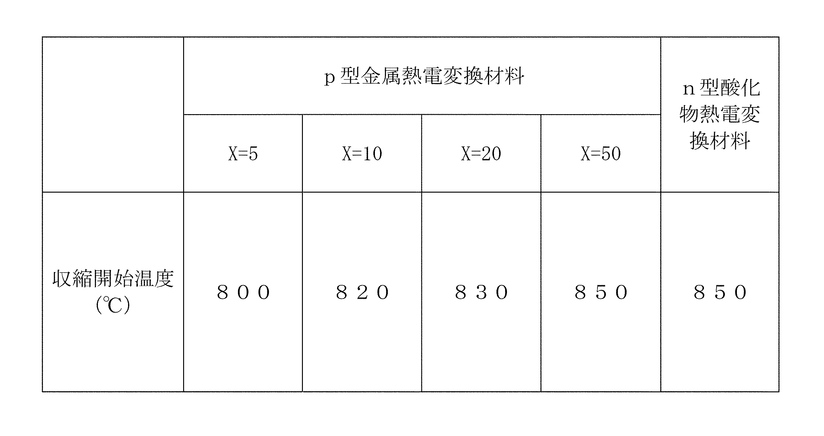
前述のn型酸化物熱電変換材料シート、およびp型金属熱電変換材料シートをそれぞれ4枚積層し、これを等方静水圧プレス法にて180MPaで圧着した後、ダイシングソーにより幅5mm、長さ15mmの大きさに切断し、収縮開始温度測定用の試料を作製した。この試料を大気中、270℃で脱脂した後、熱機械分析(TMA)により、収縮開始温度を測定した。なお、収縮開始温度とは、熱機械分析(TMA)において、昇温時に収縮が開始する温度を意味する。上述のようにして測定した収縮開始温度の測定結果を、表2に示す。
前述のn型酸化物熱電変換材料シート、およびp型金属熱電変換材料シートをそれぞれ4枚積層し、これを等方静水圧プレス法にて180MPaで圧着した後、ダイシングソーにより幅5mm、長さ15mmの大きさに切断し、収縮開始温度測定用の試料を作製した。この試料を大気中、270℃で脱脂した後、熱機械分析(TMA)により、収縮開始温度を測定した。なお、収縮開始温度とは、熱機械分析(TMA)において、昇温時に収縮が開始する温度を意味する。上述のようにして測定した収縮開始温度の測定結果を、表2に示す。
(6)比較用の熱電変換素子(比較例)の作製
p型熱電変換材料、n型熱電変換材料、絶縁材料に、いずれも酸化物材料を用いて、図5に示すような構造を有する比較用の熱電変換素子(特許文献1のものと同様の構成を備えた熱電変換素子)を作製した。
p型熱電変換材料、n型熱電変換材料、絶縁材料に、いずれも酸化物材料を用いて、図5に示すような構造を有する比較用の熱電変換素子(特許文献1のものと同様の構成を備えた熱電変換素子)を作製した。
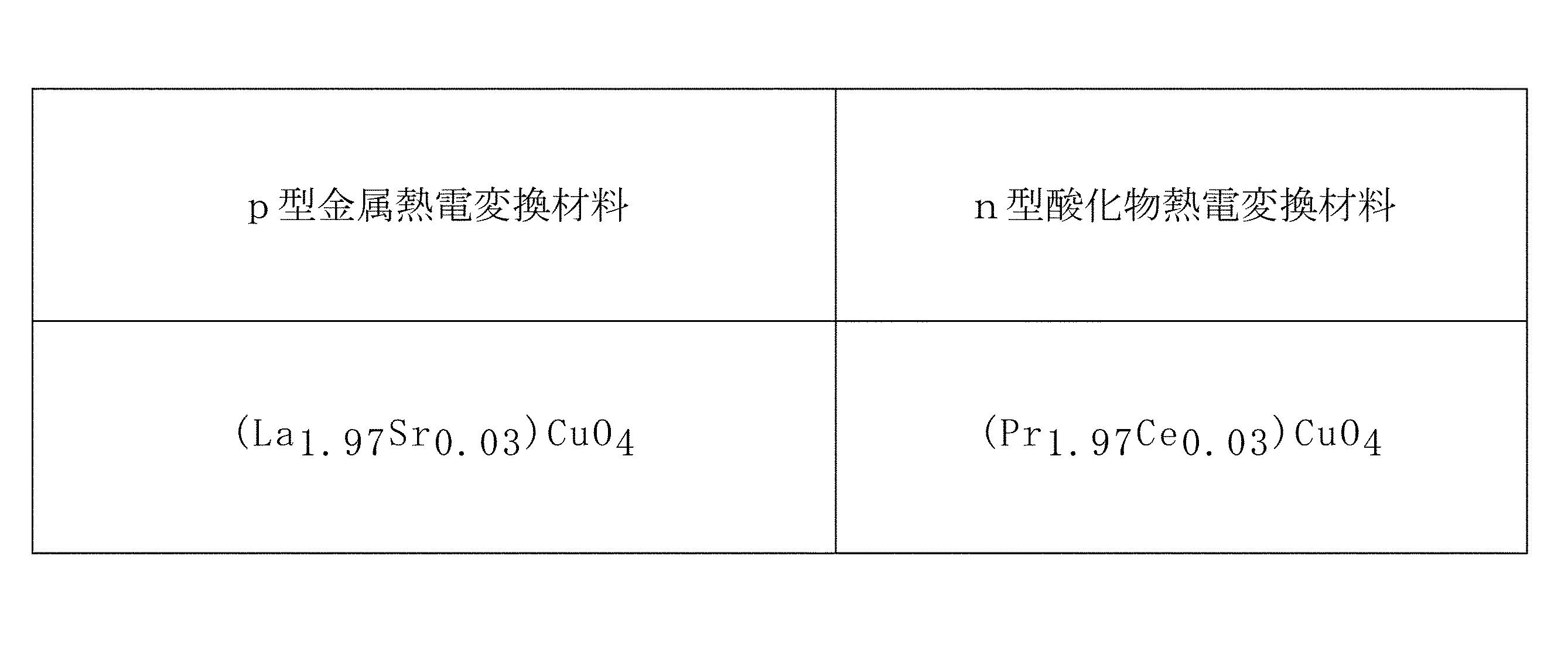
まず、p型熱電変換材料の出発原料として、La2O3,SrCO3,CuOを用意するとともに、n型熱電変換材料の出発原料として、Pr6O11、CeO2、CuOを用意した。そして、これらの出発原料を表3の組成となるように秤量した。
秤量した原料粉末をボールミルに純水(溶媒)、PSZメディアとともに投入して、16時間ボールミル粉砕を行った。得られたスラリーを乾燥させた後、大気中、900℃で仮焼した。
得られた仮焼粉末を、5時間ボールミル粉砕して得た粉末に、純水、バインダなどを添加して、さらに16時間混合することによりスラリーを得た。
このスラリーをドクターブレード法によりシート化し、焼成後の厚みが30μmとなるようなp型酸化物熱電変換材料シート、およびn型酸化物熱電変換材料シートを作製した。
このスラリーをドクターブレード法によりシート化し、焼成後の厚みが30μmとなるようなp型酸化物熱電変換材料シート、およびn型酸化物熱電変換材料シートを作製した。
また、絶縁体の材料として、Mg2SiO4粉末、ガラス粉末、ワニス、および溶剤を混合し、ロール機で混錬して絶縁ペーストを作製した。
それから、上述のようにして作製したp型酸化物熱電変換材料シート、およびn型酸化物熱電変換材料シート上に、作製した絶縁ペーストをそれぞれに厚み15μmとなるように印刷した。
その後、絶縁ペーストを印刷していないp型酸化物熱電変換材料シートを3枚、絶縁ペーストを印刷したp型酸化物熱電変換材料を1枚、絶縁ペーストを印刷していないn型酸化物熱電変換材料シートを3枚、絶縁ペーストを印刷したn型酸化物熱電変換材料シートを1枚の順に積層し、これを合計25対となるように各シートを順次積層して、積層体ブロックを作製した。ただし、最後に積層される1枚のn型酸化物熱電変換材料シートは絶縁ペーストが印刷されていないものを用い、最終的に、積層方向の一方側端面および他方側端面には絶縁材層が形成されていない熱電変換素子が得られるようにした。
その後、作製した積層体を等方静水圧プレス法にて180MPaで圧着した後、ダイシングソーにより所定の大きさに切断することにより、未焼成の積層体(積層素子)を得た。
得られた積層体を、大気中、480℃で脱脂した後、900~1050℃で焼成を行い、焼成体を得た。そして、この焼成体を研磨し、両側面の下端側領域にAgペーストをスクリーン印刷し、焼きつけることにより電力取り出し用の電極を形成した。これにより、p型熱電変換材料、n型熱電変換材料、絶縁材料として、全て酸化物材料を用いた熱電変換素子が得られる。
[評価]
上述のようにして作製した本発明の実施例にかかる試料および比較例の試料について、外観を観察し、p型熱電変換材料とn型熱電変換材料の接合面への、クラックや剥離などの欠陥の発生の有無、すなわち、未焼成の積層体を焼成して共焼結させる工程(同時焼成工程)における欠陥の発生の有無を調べた。その結果を表4に示す。
上述のようにして作製した本発明の実施例にかかる試料および比較例の試料について、外観を観察し、p型熱電変換材料とn型熱電変換材料の接合面への、クラックや剥離などの欠陥の発生の有無、すなわち、未焼成の積層体を焼成して共焼結させる工程(同時焼成工程)における欠陥の発生の有無を調べた。その結果を表4に示す。

表4に示すように、実施例の試料(試料番号1~4の試料)および比較例の試料(試料番号5の試料)においては、未焼成の積層体を焼成して共焼結させる工程で、p型熱電変換材料とn型熱電変換材料の接合面への、クラックや剥離などの欠陥の発生は認められなかった。
これは、実施例の試料においては、n型酸化物熱電変換材料の収縮開始温度が850℃であるのに対し、p型金属熱電変換材料の収縮開始温度は800~850℃であり、その差が50℃以下であり、焼成時の両者の熱収縮挙動が近く、クラックや剥離などの欠陥が発生しなかったものと考えられる。
これは、実施例の試料においては、n型酸化物熱電変換材料の収縮開始温度が850℃であるのに対し、p型金属熱電変換材料の収縮開始温度は800~850℃であり、その差が50℃以下であり、焼成時の両者の熱収縮挙動が近く、クラックや剥離などの欠陥が発生しなかったものと考えられる。
さらに、実施例の試料(試料番号1~4の試料)および比較例の試料(試料番号5の試料)の下端の温度を20℃、上端の温度を320℃に調整し、電子負荷装置で試料に接続する負荷を変化させて、電圧値および電流値を測定することにより、出力が最大となる値を測定した。また、各試料の寸法をマイクロメーターを用いて測定した。
上述のようにして、電子負荷装置を用いて電圧値および電流値を測定することにより出力を評価した結果を表5に示す。
上述のようにして、電子負荷装置を用いて電圧値および電流値を測定することにより出力を評価した結果を表5に示す。

なお、出力を評価するにあたっては、電子負荷装置により電圧値および電流値を測定し、出力が得られた試料については○とし、出力が得られた試料のうち、比較例(試料番号5の試料)よりも単位面積当たりの出力が大きい試料を◎として評価した。
表5に示すように、実施例の試料(試料番号1~4の試料)のうち、p型金属熱電変換材料に含まれるn型酸化物熱電変換材料の割合(X)が50重量%である試料番号4の試料は、比較例の試料と同等の出力を示し、p型金属熱電変換材料に含まれるn型酸化物熱電変換材料の割合(X)が5~20重量%である試料番号1~3の実施例の試料は、比較例の試料よりも大きい出力を示すことが確認された。
なお、試料番号3の実施例の試料について調べた出力特性を図2に示す。図2に示すように、試料番号3の実施例の試料は良好な出力特性を備えていることがわかる。
また、試料番号3の実施例の試料、および、試料番号5の比較例の試料について求めた出力から、単位面積当たりの出力を計算した結果を表6に示す。
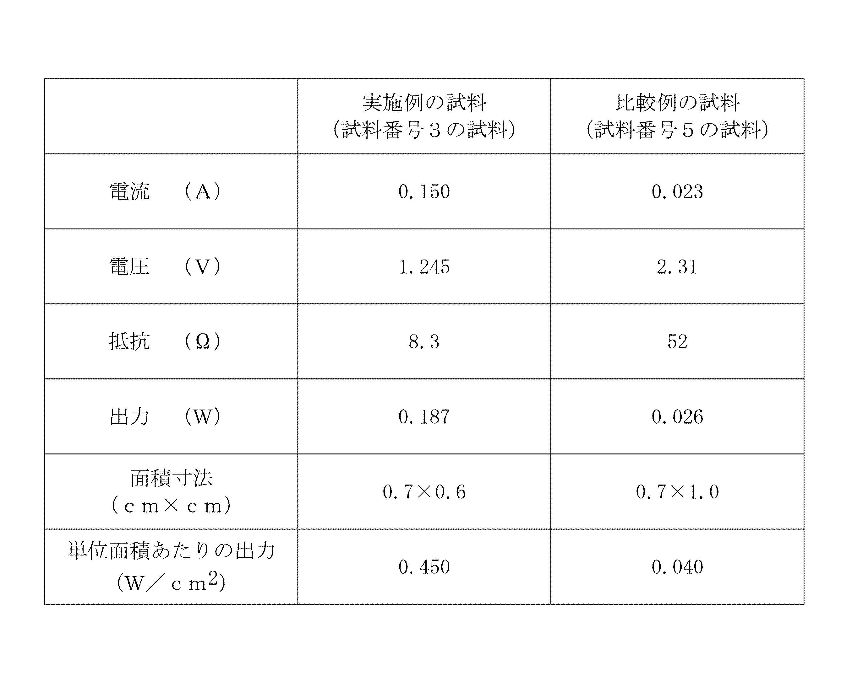
表6に示すように、試料番号3の本発明の実施例にかかる試料の場合、試料番号5の比較例の試料に比べて、出力を高めることができた。なお、試料番号3の試料番号5に対する出力の向上の割合は、11.25倍(0.45/0.040=11.25倍)であった。
上記実施例より、p型金属熱電変換材料として、5~50重量%の割合でn型酸化物熱電変換材料を含有する材料を用いることにより、異種材料間(すなわち、p型金属熱電変換材料-n型酸化物熱電変換材料間)での共焼結を実現できること、および、そのようにして製造される熱電変換素子が良好な出力特性を示すことが確認された。なお、上述のように共焼結が可能になることにより、電極を介して接続する場合のような電極作製工程や、電極とp型金属熱電変換材料やn型酸化物熱電変換材料を接合させる工程などが不要になり、製造コストの低減を図ることができる。
上記実施例では、p型金属熱電変換材料に含有させるn型酸化物熱電変換材料の割合(上述のXの値)を5~50重量%の範囲としているが、p型金属熱電変換材料に含有させるn型酸化物熱電変換材料の割合(上述のXの値)が50重量%を超えると、ゼーベック係数が小さくなる傾向があるため、通常は、n型酸化物熱電変換材料の割合は50重量%以下とすることが望ましい。
また、p型金属熱電変換材料に含有させるn型酸化物熱電変換材料の割合(上述のXの値)が5重量%未満になると、同時焼成を行った場合に、p型金属熱電変換材料に含有させるn型酸化物熱電変換材料の接合面(界面)に剥離やクラックが発生する傾向があり、通常は、n型酸化物熱電変換材料の割合は5重量%以上とすることが望ましい。
したがって、p型金属熱電変換材料として、n型酸化物熱電変換材料を含有する材料を用いる場合、通常は、n型酸化物熱電変換材料の含有割合(添加量)は、5~50重量%の範囲とすることが好ましく、さらに、出力特性を考慮すれば、5~20重量%の範囲とすることがより好ましい。
上記実施例では、p型金属熱電変換材料に、n型酸化物熱電変換材料を含有させることで、両者の収縮開始温度の差を50℃以内としているが、他の方法、例えば熱電変換材料の組成や、熱電変換材料に対する添加物を調整するなどの方法によっても、両者の収縮開始温度の差を減少させることが可能である。
なお、上記実施例では、n型酸化物熱電変換材料用の原料として、各成分の酸化物、あるいは炭酸塩を使用したが、焼成によって金属酸化物を形成しうるものであれば、水酸化物、アルコキシドなど、他の化合物を使用することも可能である。
また、p型金属熱電変換材料用の原料として、Ni粉末、Mo粉末を使用したが、Moに代えてCrを用いることも可能であり、その場合にも、同等の熱電材料特性を得ることが可能である。p型金属熱電変換材料用の原料としては、さらにその他の材料を用いることも可能である。
また、本発明では、n型酸化物熱電変換材料やp型金属熱電変換材料の出発原料となる粉末について、粒径などに特別の制約はない。しかし、均一混合を考慮して粒径などの条件を選択することが好ましい。ボールミルによる原料の混合時間などの条件についても特に制約はなく、均一混合を考慮して適宜決定することができる。また、混合にはボールミル以外の装置を用いることも可能である。
また、上記実施例では、表1の組成となるように各原料を秤量しているが、Mo、La2O3、その他の添加物は、求められる熱電特性、発電特性、共焼結に必要な条件などによって適宜選択される。また、共焼結に必要な場合には、他元素を添加してもよい。
また、上記実施例では、1300℃で仮焼を行ったが、仮焼の際の焼成方法や焼成条件、仮焼に用いる設備などに特に制約はない。ただし、仮焼温度があまり低くなると反応が進みにくくなるため、通常は、1200℃以上の温度で焼成(仮焼)を行うことが好まし
い。
い。
また、上記実施例では、仮焼後の粉末のボールミルによる混合時間を5時間としたが、p型金属熱電変換材料とn型酸化物熱電変換材料とを共焼結できればよく、特別の制約はない。
また、上記実施例では、1200~1350℃、酸素分圧10-10~10-15MPaの還元雰囲気中で本焼成を行ったが、本焼成に加圧焼成などの特別な焼成方法を適用する必要はない。しかし、ホットプレス、SPS焼結(放電プラズマ焼結)、HIP焼結などの加圧焼成を適用しても、本発明の熱電変換素子を作製できることは言うまでもない。また、本焼成の温度にも特別の制約はない。
また、上記実施例では、積層体の圧着に等方静水圧プレス法を用いているが、圧着方法はこれに限られるものではなく、他の方法を使用してもよい。
また、焼成雰囲気はNi合金が酸化しない雰囲気であれば特に問題はないが、低い焼成温度では焼結が進まないことから、焼結体の相対密度が90%以上となる温度で、かつ、共焼結させることが可能な温度で焼成することが望ましい。
また、n型酸化物熱電変換材料は焼成温度、酸素分圧によって熱電特性が大きく変化することから、最適な条件を適宜選択することが望ましい。
また、n型酸化物熱電変換材料は焼成温度、酸素分圧によって熱電特性が大きく変化することから、最適な条件を適宜選択することが望ましい。
また、上記実施例では、絶縁体(複合酸化物絶縁材料)にZr0.97Y0.03O2粉末を使用し、ガラスの添加は行っていないが、添加することも可能である。絶縁材料である酸化物とガラスの割合は、p型金属熱電変換材料、n型酸化物熱電変換材料、絶縁体(複合酸化物絶縁材料)の共焼結に必要な条件によって適宜選択することが可能である。
また、ガラスを添加する場合のガラスの構成元素については特に制約はない。また、ガラスの含有割合も、p型金属熱電変換材料およびn型酸化物熱電変換材料と共焼結することができさえすれば特に制約はないが、ガラスの含有割合が多くなりすぎると、熱電変換材料に拡散して出力特性が低下するため、複合酸化物絶縁材料中の割合が10重量%以下となるように含有させることが好ましい。
また、ガラスを用いる場合において、そのガラス軟化点には特に制約はないが、実施例のように、積層体の焼成温度(本焼成温度)を1200~1350℃とした場合、ガラス軟化点が低いと、ガラスの構成元素が熱電変換材料に拡散して出力特性の低下を招くため、ガラス軟化点が1000℃以上のガラスを用いることが好ましい。
また、p型金属熱電変換材料、n型酸化物熱電変換材料、および複合酸化物絶縁材料の厚み、pn接合対の接続数(対数)などに関しても特に制約はなく、目標とする起電力や電流、使用する負荷の抵抗などを考慮して、適宜選択することができる。
表1のp型金属熱電変換材料の欄の式:
Ni0.9Mo0.1(100-X) wt%+(Sr0.965La0.035)TiO3X wt%
におけるXの値、すなわち、p型金属熱電変換材料へのn型酸化物熱電変換材料の混合比を20wt%としたp型熱電変換材料と、表1に示すn型酸化物熱電変換材料((Sr0.965La0.035)TiO3)を用いて、p型金属熱電変換材料シートおよびn型酸化物熱電変換材料シートを作製した。
Ni0.9Mo0.1(100-X) wt%+(Sr0.965La0.035)TiO3X wt%
におけるXの値、すなわち、p型金属熱電変換材料へのn型酸化物熱電変換材料の混合比を20wt%としたp型熱電変換材料と、表1に示すn型酸化物熱電変換材料((Sr0.965La0.035)TiO3)を用いて、p型金属熱電変換材料シートおよびn型酸化物熱電変換材料シートを作製した。
また、絶縁体(複合酸化物絶縁材料)を形成するための材料として、Zr0.97Y0.03O2粉末、ワニス、および溶剤を混合し、ロール機で混錬して絶縁ペーストを作製した。
そして、p型金属熱電変換材料シート、n型酸化物熱電変換材料シート、および絶縁ペーストの厚みを、それぞれ100μm、25μm、5μm、pn積層数を50対となるように積層して、幅6mm、長さ7mm、厚み2.7mmの熱電変換素子(積層型熱電変換素子)を作製した。なお、熱電変換素子(積層型熱電変換素子)の製造方法は、上記実施例1の(4)熱電変換素子の作製の欄における熱電変換素子の製造方法に準じた。
そして、この熱電変換素子を用いて図3に示すような構成を有する通信装置(ハーベスティングモジュール)Mを作製した。
この通信装置(ハーベスティングモジュール)Mは、電源マネジメント回路部21と、無線通信送受信部22と、発電素子23とを備えた通信装置であって、発電素子23として、上述のようにして作製した熱電変換素子(積層型熱電変換素子)が用いられている。なお、発電素子23としては、上述の積層型熱電変換素子1個が用いられている。
この通信装置(ハーベスティングモジュール)Mは、電源マネジメント回路部21と、無線通信送受信部22と、発電素子23とを備えた通信装置であって、発電素子23として、上述のようにして作製した熱電変換素子(積層型熱電変換素子)が用いられている。なお、発電素子23としては、上述の積層型熱電変換素子1個が用いられている。
電源マネジメント回路21は、DC-DCコンバータ(電源回路)21a、蓄電池(コンデンサ)21bを備えている。
さらに、この実施例の通信装置(ハーベスティングモジュール)Mは、センサ24a、ID24bを備えたセンサ部24を備えている。
さらに、この実施例の通信装置(ハーベスティングモジュール)Mは、センサ24a、ID24bを備えたセンサ部24を備えている。
電源マネジメント回路21は、最低入力電圧20mVのDC-DCコンバータ(リニアテクノロジー社製 LTC3108)(電源回路21a)で、電圧を3.5Vに昇圧して、100μFのコンデンサ(蓄電部21b)に蓄電し、充電が完了した段階で、無線信号が送信される回路とした。
そして、この通信装置(ハーベスティングモジュール)Mを用い、発電素子23において発電を行って、無線信号を送信し、その性能を確認した。
ただし、無線信号の送信を行うにあたっては、図3のセンサ24aを搭載しない状態で、IDを送信するのみの動作を行わせた。
ただし、無線信号の送信を行うにあたっては、図3のセンサ24aを搭載しない状態で、IDを送信するのみの動作を行わせた。
その結果、発電素子23において、10℃の温度差で、25mV、100μWの発電を行うことができ、約15secのサイクルで、無線信号を送信できることが確認された。
本発明は、さらにその他の点においても上記実施例に限定されるものではなく、p型金属熱電変換材料およびn型酸化物熱電変換材料の具体的な組成やその原料などの熱電変換素子の具体的な構成、製造工程での焼成条件などに関し、発明の範囲内において、種々の応用、変形を加えることが可能である。
10 pn接合対
11 p型金属熱電変換材料
12 n型酸化物熱電変換材料
13 複合酸化物絶縁材料
20 熱電変換素子
21 電源マネジメント回路部
22 無線通信送受信部
23 発電素子
21a DC-DCコンバータ(電源回路)
21b 蓄電池(コンデンサ)
24a センサ
24b ID
M 通信装置(ハーベスティングモジュール)
11 p型金属熱電変換材料
12 n型酸化物熱電変換材料
13 複合酸化物絶縁材料
20 熱電変換素子
21 電源マネジメント回路部
22 無線通信送受信部
23 発電素子
21a DC-DCコンバータ(電源回路)
21b 蓄電池(コンデンサ)
24a センサ
24b ID
M 通信装置(ハーベスティングモジュール)
Claims (9)
- 金属を主たる成分とするp型金属熱電変換材料と、酸化物を主たる成分とするn型酸化物熱電変換材料と、複合酸化物を主たる成分とする複合酸化物絶縁材料とを備え、
前記p型金属熱電変換材料と、前記n型酸化物熱電変換材料との接合面の一部の領域においては、前記p型金属熱電変換材料と前記n型酸化物熱電変換材料とが直接接合し、前記接合面の他の領域では、前記p型金属熱電変換材料と前記n型酸化物熱電変換材料とが、前記複合酸化物絶縁材料を介して接合することによりpn接合対が形成されていること
を特徴とする熱電変換素子。 - 前記n型酸化物熱電変換材料として、組成式ABO3(AおよびBは1個または複数個の元素)で示されるペロブスカイト型酸化物からなるn型酸化物熱電変換材料が用いられており、
該n型酸化物熱電変換材料と、前記p型金属熱電変換材料と、前記複合酸化物絶縁材料とが、一体に共焼結されたものであることを特徴とする請求項1記載の熱電変換素子。 - 前記p型金属熱電変換材料と、前記n型酸化物熱電材料の熱機械分析における収縮開始温度の差が50℃以内であることを特徴とする請求項2記載の熱電変換素子。
- 前記p型金属熱電変換材料が、前記n型酸化物熱電材料を含むものであることを特徴とする請求項3記載の熱電変換素子。
- 前記p型金属熱電変換材料に含まれる前記n型酸化物熱電材料の割合が、5~50重量%であることを特徴とする請求項4記載の熱電変換素子。
- 前記p型金属熱電変換材料がNi合金を主たる成分とするものであり、
前記n型酸化物熱電材料を構成する組成式ABO3で示されるペロブスカイト型酸化物が、Aとして少なくともSrを含み、Bとして少なくともTiを含むペロブスカイト型酸化物であること
を特徴とする請求項2~5のいずれかに記載の熱電変換素子。 - 前記pn接合対が複数接続されており、両端には前記p型金属熱電変換材料が配設されていることを特徴とする請求項1~6のいずれかに記載の熱電変換素子。
- p型金属熱電変換材料と、n型酸化物熱電変換材料との接合面の一部の領域においては、p型金属熱電変換材料とn型酸化物熱電変換材料とが直接接合し、面の他の領域では、p型金属熱電変換材料とn型酸化物熱電変換材料とが、複合酸化物絶縁材料を介して接合された構造を有する熱電変換素子の製造方法であって、
請求項1~5のいずれかに記載されたp型金属熱電変換材料を主たる成分とするp型金属熱電変換材料シートを形成する工程と、
請求項1~5のいずれかに記載されたn型酸化物熱電変換材料を主たる成分とするn型酸化物熱電変換材料シートを形成する工程と、
前記p型金属熱電変換材料シートと前記n型酸化物熱電変換材料の少なくとも一方の、両者の接合面となる面の一部の領域に、複合酸化物を主たる成分とする複合酸化物絶縁材料を付与する工程と、
前記p型金属熱電変換材料シートと前記n型酸化物熱電変換材料シートを積層して、両者の接合面の一部の領域においては、前記p型金属熱電変換材料シートと前記n型酸化物熱電変換材料シートとが直接接合し、他の領域では、前記p型金属熱電変換材料シートと前記n型酸化物熱電変換材料シートとが、前記複合酸化物絶縁材料を介して接合された積層体を形成する工程と、
前記積層体を真空中または還元雰囲気中で焼成して、p型金属熱電変換材料とn型酸化物熱電変換材料と複合酸化物絶縁材料とが共焼結された熱電変換素子を得る工程と
を具備することを特徴とする熱電変換素子の製造方法。 - 電源マネジメント回路部と、無線通信送受信部と、発電素子とを備えた通信装置であって、
前記発電素子として、請求項1~7のいずれかに記載の熱電変換素子が用いられていること
を特徴とする通信装置。
Priority Applications (3)
| Application Number | Priority Date | Filing Date | Title |
|---|---|---|---|
| JP2012525344A JP5464274B2 (ja) | 2010-07-20 | 2011-06-14 | 熱電変換素子、その製造方法、および通信装置 |
| CN201180035405.3A CN103003969B (zh) | 2010-07-20 | 2011-06-14 | 热电转换元件、其制造方法及通信装置 |
| US13/738,029 US9054274B2 (en) | 2010-07-20 | 2013-01-10 | Thermoelectric conversion element, method for manufacturing same, and communication device |
Applications Claiming Priority (2)
| Application Number | Priority Date | Filing Date | Title |
|---|---|---|---|
| JP2010-162842 | 2010-07-20 | ||
| JP2010162842 | 2010-07-20 |
Related Child Applications (1)
| Application Number | Title | Priority Date | Filing Date |
|---|---|---|---|
| US13/738,029 Continuation US9054274B2 (en) | 2010-07-20 | 2013-01-10 | Thermoelectric conversion element, method for manufacturing same, and communication device |
Publications (1)
| Publication Number | Publication Date |
|---|---|
| WO2012011334A1 true WO2012011334A1 (ja) | 2012-01-26 |
Family
ID=45496763
Family Applications (1)
| Application Number | Title | Priority Date | Filing Date |
|---|---|---|---|
| PCT/JP2011/063554 Ceased WO2012011334A1 (ja) | 2010-07-20 | 2011-06-14 | 熱電変換素子、その製造方法、および通信装置 |
Country Status (4)
| Country | Link |
|---|---|
| US (1) | US9054274B2 (ja) |
| JP (1) | JP5464274B2 (ja) |
| CN (1) | CN103003969B (ja) |
| WO (1) | WO2012011334A1 (ja) |
Cited By (4)
| Publication number | Priority date | Publication date | Assignee | Title |
|---|---|---|---|---|
| WO2017082042A1 (ja) * | 2015-11-12 | 2017-05-18 | 株式会社村田製作所 | 熱電変換素子 |
| WO2017163507A1 (ja) * | 2016-03-25 | 2017-09-28 | 株式会社村田製作所 | 積層型熱電変換素子 |
| WO2022059443A1 (ja) * | 2020-09-16 | 2022-03-24 | 国立研究開発法人物質・材料研究機構 | 熱電材料、その製造方法、および、熱電発電素子 |
| US12622172B2 (en) | 2020-09-16 | 2026-05-05 | National Institute For Materials Science | Thermoelectric material, method for producing same, and thermoelectric power generation element |
Families Citing this family (4)
| Publication number | Priority date | Publication date | Assignee | Title |
|---|---|---|---|---|
| US10491866B2 (en) * | 2015-08-26 | 2019-11-26 | Ricoh Company, Ltd. | Actuator controlling device, drive system, video device, image projection device, and actuator controlling method |
| WO2017168969A1 (ja) * | 2016-03-31 | 2017-10-05 | 株式会社村田製作所 | 熱電変換モジュールおよび熱電変換モジュールの製造方法 |
| CN108886083B (zh) * | 2016-03-31 | 2022-05-10 | 株式会社村田制作所 | 热电转换元件以及热电转换元件的制造方法 |
| RU2745910C1 (ru) * | 2020-10-08 | 2021-04-02 | Федеральное государственное автономное образовательное учреждение высшего образования «Дальневосточный федеральный университет» (ДВФУ) | Способ получения бифазной термоэлектрической керамики |
Citations (6)
| Publication number | Priority date | Publication date | Assignee | Title |
|---|---|---|---|---|
| JPH01262678A (ja) * | 1988-04-14 | 1989-10-19 | Murata Mfg Co Ltd | 積層熱電素子およびその製造方法 |
| JPH05198847A (ja) * | 1991-10-07 | 1993-08-06 | Matsushita Electric Ind Co Ltd | 電子冷却素子 |
| WO1995017020A1 (en) * | 1993-12-16 | 1995-06-22 | Mitsubishi Materials Corporation | Thermoelectric conversion element, thermoelectric conversion element array, and thermal displacement converter |
| JP2008182160A (ja) * | 2007-01-26 | 2008-08-07 | Nippon Steel Chem Co Ltd | フレキシブル熱電変換素子及びその製造方法 |
| JP2008199735A (ja) * | 2007-02-09 | 2008-08-28 | Toshiba Corp | 無線icネットワーク用無線ic |
| WO2009001691A1 (ja) * | 2007-06-22 | 2008-12-31 | Murata Manufacturing Co., Ltd. | 熱電変換素子、熱電変換モジュール、および熱電変換素子の製造方法 |
Family Cites Families (4)
| Publication number | Priority date | Publication date | Assignee | Title |
|---|---|---|---|---|
| US3902923A (en) * | 1970-12-28 | 1975-09-02 | Dow Chemical Co | Thermoelectric materials |
| US5275001A (en) | 1991-10-07 | 1994-01-04 | Matsushita Electric Industrial Co., Ltd. | Thermoelectric cooling device |
| JP4285665B2 (ja) * | 1997-12-27 | 2009-06-24 | 日立金属株式会社 | 熱電変換素子 |
| JP2009099686A (ja) * | 2007-10-15 | 2009-05-07 | Sumitomo Chemical Co Ltd | 熱電変換モジュール |
-
2011
- 2011-06-14 CN CN201180035405.3A patent/CN103003969B/zh active Active
- 2011-06-14 JP JP2012525344A patent/JP5464274B2/ja active Active
- 2011-06-14 WO PCT/JP2011/063554 patent/WO2012011334A1/ja not_active Ceased
-
2013
- 2013-01-10 US US13/738,029 patent/US9054274B2/en active Active
Patent Citations (6)
| Publication number | Priority date | Publication date | Assignee | Title |
|---|---|---|---|---|
| JPH01262678A (ja) * | 1988-04-14 | 1989-10-19 | Murata Mfg Co Ltd | 積層熱電素子およびその製造方法 |
| JPH05198847A (ja) * | 1991-10-07 | 1993-08-06 | Matsushita Electric Ind Co Ltd | 電子冷却素子 |
| WO1995017020A1 (en) * | 1993-12-16 | 1995-06-22 | Mitsubishi Materials Corporation | Thermoelectric conversion element, thermoelectric conversion element array, and thermal displacement converter |
| JP2008182160A (ja) * | 2007-01-26 | 2008-08-07 | Nippon Steel Chem Co Ltd | フレキシブル熱電変換素子及びその製造方法 |
| JP2008199735A (ja) * | 2007-02-09 | 2008-08-28 | Toshiba Corp | 無線icネットワーク用無線ic |
| WO2009001691A1 (ja) * | 2007-06-22 | 2008-12-31 | Murata Manufacturing Co., Ltd. | 熱電変換素子、熱電変換モジュール、および熱電変換素子の製造方法 |
Cited By (8)
| Publication number | Priority date | Publication date | Assignee | Title |
|---|---|---|---|---|
| WO2017082042A1 (ja) * | 2015-11-12 | 2017-05-18 | 株式会社村田製作所 | 熱電変換素子 |
| JPWO2017082042A1 (ja) * | 2015-11-12 | 2018-08-30 | 株式会社村田製作所 | 熱電変換素子 |
| WO2017163507A1 (ja) * | 2016-03-25 | 2017-09-28 | 株式会社村田製作所 | 積層型熱電変換素子 |
| JPWO2017163507A1 (ja) * | 2016-03-25 | 2018-11-08 | 株式会社村田製作所 | 積層型熱電変換素子 |
| WO2022059443A1 (ja) * | 2020-09-16 | 2022-03-24 | 国立研究開発法人物質・材料研究機構 | 熱電材料、その製造方法、および、熱電発電素子 |
| JPWO2022059443A1 (ja) * | 2020-09-16 | 2022-03-24 | ||
| JP7448259B2 (ja) | 2020-09-16 | 2024-03-12 | 国立研究開発法人物質・材料研究機構 | 熱電材料、その製造方法、および、熱電発電素子 |
| US12622172B2 (en) | 2020-09-16 | 2026-05-05 | National Institute For Materials Science | Thermoelectric material, method for producing same, and thermoelectric power generation element |
Also Published As
| Publication number | Publication date |
|---|---|
| CN103003969A (zh) | 2013-03-27 |
| JP5464274B2 (ja) | 2014-04-09 |
| US9054274B2 (en) | 2015-06-09 |
| US20140020729A1 (en) | 2014-01-23 |
| CN103003969B (zh) | 2015-11-25 |
| JPWO2012011334A1 (ja) | 2013-09-09 |
Similar Documents
| Publication | Publication Date | Title |
|---|---|---|
| CN101681977B (zh) | 热电转换元件、热电转换模块及热电转换元件的制造方法 | |
| JP5464274B2 (ja) | 熱電変換素子、その製造方法、および通信装置 | |
| JP4111006B2 (ja) | 誘電体セラミックおよびその製造方法ならびに積層セラミックコンデンサ | |
| WO2010058464A1 (ja) | 熱電変換モジュール | |
| KR20130045915A (ko) | 적층 세라믹 콘덴서 | |
| JP4936825B2 (ja) | 積層セラミックコンデンサ | |
| JP5098589B2 (ja) | 熱電変換モジュール | |
| JP2011195425A (ja) | 誘電体セラミックおよび積層セラミックコンデンサ | |
| JP2008305844A (ja) | 積層セラミックコンデンサ及びその製造方法 | |
| JP5007748B2 (ja) | 熱電変換モジュールおよび熱電変換モジュールの製造方法 | |
| TW200917300A (en) | Dielectric ceramic and laminated ceramic capacitor | |
| WO2006082833A1 (ja) | 積層セラミックコンデンサ、及び該積層セラミックコンデンサの製造方法 | |
| JP2012248819A (ja) | 熱電変換素子およびその製造方法 | |
| JP2010173910A (ja) | 誘電体セラミックおよび積層セラミックコンデンサ | |
| JPWO2017082042A1 (ja) | 熱電変換素子 | |
| WO2011138915A1 (ja) | 高温構造材料、固体電解質形燃料電池用構造体および固体電解質形燃料電池 | |
| JP5470326B2 (ja) | 成形体 | |
| JP4780306B2 (ja) | 積層型サーミスタ及びその製造方法 | |
| US20180366630A1 (en) | Multilayer thermoelectric transducer | |
| JPWO2009142240A1 (ja) | 熱電変換モジュールおよび熱電変換モジュールの製造方法 | |
| JP2003209304A (ja) | 積層型圧電セラミック素子の製造方法 | |
| JP2008078516A (ja) | 積層セラミックコンデンサおよびその製法 | |
| WO2008038519A1 (fr) | Élément de conversion thermoélectrique, module de conversion thermoélectrique et procédé de production d'élément de conversion thermoélectrique | |
| JP6218202B2 (ja) | 固体電解質、及び積層型電子部品、並びに積層型電子部品の製造方法 | |
| JP5354834B2 (ja) | 誘電体磁器組成物及び磁器コンデンサとそれらの製造方法 |
Legal Events
| Date | Code | Title | Description |
|---|---|---|---|
| 121 | Ep: the epo has been informed by wipo that ep was designated in this application |
Ref document number: 11809508 Country of ref document: EP Kind code of ref document: A1 |
|
| WWE | Wipo information: entry into national phase |
Ref document number: 2012525344 Country of ref document: JP |
|
| NENP | Non-entry into the national phase |
Ref country code: DE |
|
| 122 | Ep: pct application non-entry in european phase |
Ref document number: 11809508 Country of ref document: EP Kind code of ref document: A1 |