WO2012004844A1 - Garniture de frein et son procédé de production - Google Patents
Garniture de frein et son procédé de production Download PDFInfo
- Publication number
- WO2012004844A1 WO2012004844A1 PCT/JP2010/061385 JP2010061385W WO2012004844A1 WO 2012004844 A1 WO2012004844 A1 WO 2012004844A1 JP 2010061385 W JP2010061385 W JP 2010061385W WO 2012004844 A1 WO2012004844 A1 WO 2012004844A1
- Authority
- WO
- WIPO (PCT)
- Prior art keywords
- brake lining
- brake
- hardness
- lining
- manufacturing
- Prior art date
Links
Images


Classifications
-
- F—MECHANICAL ENGINEERING; LIGHTING; HEATING; WEAPONS; BLASTING
- F16—ENGINEERING ELEMENTS AND UNITS; GENERAL MEASURES FOR PRODUCING AND MAINTAINING EFFECTIVE FUNCTIONING OF MACHINES OR INSTALLATIONS; THERMAL INSULATION IN GENERAL
- F16D—COUPLINGS FOR TRANSMITTING ROTATION; CLUTCHES; BRAKES
- F16D69/00—Friction linings; Attachment thereof; Selection of coacting friction substances or surfaces
- F16D2069/002—Combination of different friction materials
-
- F—MECHANICAL ENGINEERING; LIGHTING; HEATING; WEAPONS; BLASTING
- F16—ENGINEERING ELEMENTS AND UNITS; GENERAL MEASURES FOR PRODUCING AND MAINTAINING EFFECTIVE FUNCTIONING OF MACHINES OR INSTALLATIONS; THERMAL INSULATION IN GENERAL
- F16D—COUPLINGS FOR TRANSMITTING ROTATION; CLUTCHES; BRAKES
- F16D69/00—Friction linings; Attachment thereof; Selection of coacting friction substances or surfaces
- F16D69/04—Attachment of linings
- F16D2069/0425—Attachment methods or devices
- F16D2069/0483—Lining or lining carrier material shaped in situ
-
- F—MECHANICAL ENGINEERING; LIGHTING; HEATING; WEAPONS; BLASTING
- F16—ENGINEERING ELEMENTS AND UNITS; GENERAL MEASURES FOR PRODUCING AND MAINTAINING EFFECTIVE FUNCTIONING OF MACHINES OR INSTALLATIONS; THERMAL INSULATION IN GENERAL
- F16D—COUPLINGS FOR TRANSMITTING ROTATION; CLUTCHES; BRAKES
- F16D69/00—Friction linings; Attachment thereof; Selection of coacting friction substances or surfaces
- F16D69/04—Attachment of linings
- F16D2069/0425—Attachment methods or devices
- F16D2069/0491—Tools, machines, processes
Definitions
- the present invention relates to a brake lining used for, for example, an elevator hoisting machine brake, an electric motor brake, an automobile brake and the like, and a manufacturing method thereof.
- a soft member is bonded to both ends of the lining to facilitate deformation of both ends of the lining, thereby preventing local contact and suppressing squeal (for example, (See Patent Document 3).
- the noise is reduced when the porosity is increased, but the strength is lowered and there is a risk of breakage. For this reason, it is difficult to select a material for adjusting the porosity, and it is necessary to mix a plurality of materials that are not necessary for ensuring good friction characteristics, or to mix a plurality of fibers as the base material. There is a problem that the manufacturing cost of the lining increases.
- the hoisting machine brake performs a braking operation after the rotation of the disk or rotor is stopped. Even when the object to be braked is stationary, the impact at the time of contact with the lining Sound is generated.
- the present invention has been made to solve the above-described problems, and has an object to obtain a brake lining that has high wear resistance and can suppress noise such as squeal and impact noise, and a method for manufacturing the same.
- the brake lining according to the present invention brakes the rotation of the braked rotating body by being pressed against the braked rotating body, and is directed from the end in the sliding direction relative to the braked rotating body toward the center.
- the hardness gradually increases.
- the brake lining according to the present invention brakes the rotation of the braked rotating body by being pressed against the braked rotating body, and is provided near the center of the lining main body and the lining main body. Also has a plurality of high hardness portions having high hardness.
- the method for manufacturing a brake lining according to the present invention includes a step of mixing a base material and a plurality of blended materials to form a mixed material, a step of charging the mixed material into a die, heating and pressurizing with a punch, and forming.
- the manufacturing method of the brake lining includes a step of mixing a base material and a plurality of blended materials to form a mixed material, a step of charging the mixed material into a die, heating and pressurizing with a punch, and a molded molding
- the brake lining manufacturing method is a brake lining manufacturing method configured by combining a high friction portion mixed with a high friction material and a high hardness portion having a hardness higher than that of the high friction portion. Then, the material of the high hardness part is put into the die and heated and pressed by the first punch having the depression formed on the pressing surface, and the high friction part is inserted into the die from the high hardness part molded body.
- the method includes a step of charging a material and molding by heating and pressing with a second punch, and a step of polishing a molded body in which a high hardness portion and a high friction portion are combined to expose the high hardness portion on the surface.
- the brake lining of the present invention is configured so that the hardness of the end portion is low, the end portion is deformed at the initial stage of contact with the braked rotating body, and the impact of the contact can be absorbed. For this reason, it is possible to reduce the vibration of the support member of the brake lining and the braked rotating body and to suppress the impact sound and squeal. Further, since it is not necessary to provide holes in the brake lining, the wear resistance can be increased. In addition, since the high hardness part with increased hardness is provided in the vicinity of the center part, the overall wear resistance can be improved, and the impact of contact with the braked rotating body can be absorbed, and the brake lining The vibration of the support member and the braked rotating body can be reduced to suppress the impact sound and squeal.
- the distance between the bottom surface in the die and the pressing surface of the punch gradually decreases from the portion corresponding to the end portion of the brake lining toward the portion corresponding to the central portion. Therefore, it is possible to change the hardness of the brake lining partially and continuously without changing the manufacturing process, and to obtain a brake lining with high wear resistance and low noise such as squeal and impact noise. Can do.
- the manufacturing process can be partially and continuously changed without particularly changing the above, and a brake lining having high wear resistance and low noise such as squealing and impact noise can be obtained.
- a brake lining in which a high friction portion and a high hardness portion are combined can be easily manufactured, and a brake lining having high wear resistance and low noise such as squealing and impact noise can be obtained.
- FIG. 3 is a plan view showing a brake lining and a brake disc of FIG. 2.
- FIG. 2 is sectional drawing which shows typically the state in the middle of manufacture of the brake lining of FIG.
- FIG. 18 is a cross-sectional view taken along line XVIII-XVIII in FIG. It is sectional drawing which shows typically the state in the middle of manufacture of the brake lining of FIG. It is a side view which shows the brake lining and brake disc by Embodiment 8 of this invention. It is sectional drawing which shows typically the state in the middle of manufacture of the brake lining of FIG.
- FIG. 1 is a cross-sectional view showing a main part of an elevator hoist according to Embodiment 1 of the present invention.
- the shaft 1 is fixed horizontally to the housing of the hoisting machine.
- a rotating body 3 (only a half is shown in the figure) is rotatably supported on the outer periphery of the shaft 1 via a pair of bearings 2a and 2b.
- the rotating body 3 includes a cylindrical sheave 3a, a disk-shaped flange portion 3b that protrudes radially outward from one axial end portion of the sheave 3a, and a radially outward end portion of the flange portion 3b.
- a cylindrical rotor mounting portion 3c protruding in the direction is integrally formed.
- the rope sheave 3a is provided with a plurality of rope grooves.
- a plurality of suspension means (ropes or belts) for suspending the car and the counterweight are wound around the sheave 3a.
- the rotating body 3 is rotated around the shaft 1 by the driving force of the hoisting machine motor.
- the hoist motor includes a motor stator fixed to the housing and a motor rotor attached to the rotor attachment portion 3c so as to face the motor stator.
- the hoisting machine is provided with a brake disk 4 (braking body to be braked) and a hoisting machine brake 5 that brakes the rotation of the rotating body 3 via the brake disk 4.
- the brake disc 4 is fixed to the flange portion 3 b and is rotated integrally with the rotating body 3.
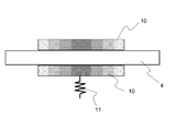
- the hoisting machine brake 5 includes a yoke 6, an electromagnetic coil 7 provided on the yoke 6, a first brake shoe 8 facing the first surface (front surface) of the brake disk 4, and a second brake disk 4.
- a brake spring 11 is provided between the shoe 8 and the yoke 6.
- the electromagnetic coil 7 When starting the traveling of the car, the electromagnetic coil 7 is excited to generate an electromagnetic attractive force, and the first brake shoe 8 is pulled away from the brake disk 4 against the spring force of the brake spring 11. As a result, the brake lining 10 is separated from both surfaces of the brake disc 4 and the braking force is released.
- the energization to the electromagnetic coil 7 is cut off, the brake lining 10 is pressed against the rotating brake disk 4, and the brake disk 4 is Friction braking. Further, when the energization of the electromagnetic coil 7 is interrupted due to a power failure while the car is running, the brake disk 4 is similarly frictionally braked and the car is stopped.
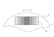
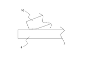
- FIG. 2 is a side view showing the brake lining 10 and the brake disc 4 of FIG. 1
- FIG. 3 is a plan view showing the brake lining 10 and the brake disc 4 of FIG.
- the hardness of each brake lining 10 gradually increases gradually from both ends in the sliding direction relative to the brake disc 4 toward the center.
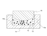
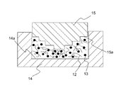
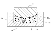
- FIG. 4 is a cross-sectional view schematically showing a state during the production of the brake lining 10 of FIG.
- the brake lining 10 is composed of fibers 12 serving as a base material and various preparation materials 13.
- the compounding material 13 includes a friction modifier, a filler, a binder, and the like.
- the fiber 12 for example, glass fiber, steel fiber, aramid fiber, carbon fiber, or potassium titanate can be used.
- the friction modifier for example, cashew dust, rubber dust, copper, zinc, alumina, or zirconia can be used.
- the filler for example, calcium carbonate, barium sulfate, calcium sulfate, tin sulfide, or the like can be used.
- the binder for example, phenol resin, melanin resin, polyimide, or the like can be used.
- a predetermined amount of a mixed material obtained by previously mixing the fiber 12 and the blended material 13 is put into the die 14. Then, the mixed material in the die 14 is molded while being pressurized and heated by the punch 15. After molding the mixed material, the molded body is polished so as to have a predetermined thickness, and the brake lining 10 can be obtained.
- the pressing surface 15a that contacts the mixed material of the punch 15 is curved in a circular arc shape.
- dye 14 becomes the narrowest in the center part.
- the density of the material increases at the center of the brake lining 10 and the hardness increases. Further, the density of the material gradually decreases and the hardness gradually decreases from the center to the end of the brake lining 10.
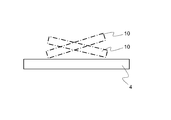
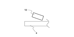
- FIG. 5 is an explanatory view showing a state in which the brake lining 10 of FIG. 1 is in contact with the brake disc 4 while being inclined
- FIG. 6 is an explanatory view showing a state in which the brake lining 10 of FIG. FIG.
- the posture of the brake lining 10 can be changed with respect to the brake disc 4 in order to keep the braking force stable. For example, even if the temperature of the brake disk 4 rises due to heat generation and the brake disk 4 is deformed, the brake lining 10 is often rotatably supported so that the contact surface pressure becomes uniform.
- the brake lining 10 vibrates and contacts the brake disc 4 as shown in FIG. Noises such as noise and squeal may become even louder.
- the brake lining 10 of the first embodiment is configured so that the hardness of the end portion is low, so that the initial stage when the brake lining 10 contacts the brake disc 4 as shown in FIG.
- the end portion is deformed and the impact of contact can be absorbed.
- the vibration of the support member of the brake lining 10 and the brake disk 4 can be reduced, and an impact sound and a squeal can be suppressed.
- the peak value of contact surface pressure can be made small by deform
- the local temperature rise of the brake lining 10 can be suppressed and braking force can be kept stable.
- the hardness of the brake lining 10 is continuously changed, there is no discontinuous change in contact surface pressure, and the surface pressure is uniformly distributed in the surface. The vibration of the disk 4 can be reduced more reliably.
- the wear resistance can be increased.
- the brake lining 10 whose hardness changes continuously can be obtained, and the hoisting machine brake 5 with high quality can be obtained at a low cost.
- FIG. 8 is a sectional view showing a main part of an elevator hoist according to Embodiment 2 of the present invention.
- the rotating body 16 includes a cylindrical sheave 16a, a disc-shaped flange portion 16b that protrudes radially outward from one axial end portion of the sheave 16a, and a radially outer end of the flange portion 16b.
- a cylindrical brake drum 16c (braking body to be braked) protruding in the axial direction from the portion is integrally formed.
- the brake lining 10 is pressed against the inner peripheral surface (braking surface) of the brake drum 16c by the spring force of the brake spring 11. Further, the brake lining 10 is pulled away from the inner peripheral surface of the brake drum 16 c by the electromagnetic attractive force of the electromagnetic coil 7.
- Other configurations are the same as those in the first embodiment.
- the drum brake having the inner peripheral surface of the brake drum 16c as the braking surface is shown.
- the brake lining 10 is used as the braking member, for example, a brake device of the type having the outer peripheral surface of the brake drum 16c as the braking surface.
- the present invention can be applied to other various brake devices as long as the brake device is used as a brake device. Therefore, the brake lining shown in the following embodiments can also be applied to various types of brake devices.
- FIG. 9 is a cross-sectional view schematically showing a state in the middle of manufacturing the brake lining according to the third embodiment of the present invention.
- the bottom surface 14a of the cavity in the die 14 is curved in a circular arc shape in cross section.
- Other configurations and manufacturing methods are the same as those in the first or second embodiment.
- the density of the material in the central portion of the brake lining 10 can be further increased, and the difference in hardness between the central portion and the end portion can be increased. .
- the radius of curvature of the pressing surface 15a and the bottom surface 14a may not be the same.
- the pressing surface 15a is curved.
- both the pressing surface 15a and the bottom surface 14a are curved.
- only the bottom surface 14a may be curved.
- FIG. 10 is a cross-sectional view schematically showing a state in the middle of manufacturing a brake lining according to Embodiment 4 of the present invention.
- the pressing surface 15a of the punch 15 has a stepped shape with the central portion protruding most toward the bottom surface 14a.
- Other configurations and manufacturing methods are the same as those in the first or second embodiment.
- the punch 15 of the fourth embodiment may be combined with the die 14 of the third embodiment. Further, the bottom surface 14a may be projected stepwise toward the punch 15 side.
- FIG. 11 is a side view showing the brake lining 17 and the brake disc 4 according to the fifth embodiment of the present invention
- FIG. 12 shows a state in which the brake lining 17 of FIG. It is explanatory drawing shown.
- the brake disk 4 of the fifth embodiment is rotated only in the direction of the arrow in FIG.
- the hardness of the brake lining 17 according to the fifth embodiment is gradually increased gradually from one end portion to the other end portion in the sliding direction relative to the brake disc 4.
- Other configurations are the same as those in the first embodiment.
- the pressing surface 15a of the punch 15 is inclined with respect to the bottom surface 14a, and the space between the pressing surface 15a and the bottom surface 14a is increased. The distance may be reduced on the side corresponding to one end of the brake lining 17.
- Other manufacturing methods are the same as those in the first embodiment.
- the brake lining 17 can be manufactured at low cost.
- the brake lining 17 as in the fifth embodiment can be applied to other types of brake devices such as a drum brake as shown in the second embodiment. Further, if the distance between the pressing surface 15a and the bottom surface 14a is gradually increased from the portion corresponding to one end portion in the length direction of the brake lining 17 toward the portion corresponding to the other end portion, the pressing surface Both 15a and the bottom surface 14a may be inclined (inclined with respect to a plane perpendicular to the pressing direction by the punch 15), or only the bottom surface 14a may be inclined. Furthermore, at least one of the pressing surface 15a and the bottom surface 14a may be curved or protruded stepwise.
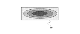
- FIG. 14 is a front view showing a brake lining 18 according to Embodiment 6 of the present invention.
- the hardness of the brake lining 18 is determined from the center in the length direction (left-right direction in the figure) and width direction (direction perpendicular to the length direction and thickness direction: up-down direction in the figure) of the brake lining 18 It is gradually lowering continuously.
- the hardness of the brake lining 18 gradually increases from both end portions in the length direction toward the center portion, and gradually increases from both end portions in the width direction toward the center portion.
- Other configurations are the same as those in the first embodiment.
- the brake lining 18 as described above is such that at least one of the pressing surface 15a of the punch 15 and the bottom surface 14a in the die 14 is curved into a spherical shape, and the mixed material charged into the die 14 is heated and pressurized, and is predetermined after molding. It can manufacture by grinding to the thickness of.
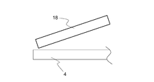
- the friction state on the braking surface is likely to change, such as an environment where the temperature and humidity change greatly, an environment where the brake disc 4 (or the brake drum 16c) is easily contaminated, or an environment where moisture is likely to adhere. is there.
- the friction state changes in this way, not only the posture change in the sliding direction (length direction) as shown in FIG. 15 but also the posture changes in the width direction as shown in FIG. Sometimes.
- the braking force can be kept stable by reducing the vibration, it is possible to provide a brake device having a stable quality even when the environment changes.
- the brake device can be made smaller and lighter.
- the brake lining 18 as in the sixth embodiment can be applied to other types of brake devices such as a drum brake as shown in the second embodiment. Further, when the brake lining 18 as in the sixth embodiment is manufactured, at least one of the pressing surface 15a of the punch 15 and the bottom surface 14a in the die 14 is projected in a step shape so that the center projects most. May be.
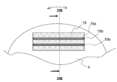
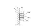
- FIG. 17 is a side view showing the brake lining 19 and the brake disc 4 according to Embodiment 7 of the present invention
- FIG. 18 is a sectional view taken along the line XVIII-XVIII of FIG.
- the brake lining 19 is composed of a lining body 19a and a plurality of (two in this case) linear high-hardness portions 19b which are provided in the lining body 19a and have higher hardness than the lining body 19a. .
- the high hardness portion 19b is provided over the entire length of the brake lining 19 in parallel with the sliding direction relative to the brake disc 4 (the length direction of the brake lining 19). Moreover, the high hardness part 19b is provided in the width direction (up-down direction of FIG. 17) of the brake lining 19 at intervals.
- the brake lining 19 as described above uses a punch 15 provided with a plurality of protrusions 15b, and the interval between the bottom surface 14a in the die 14 and the pressing surface 15a of the punch 15 is discontinuous. And can be manufactured by heating and pressurizing the mixed material. After molding, the surface of the molded body is polished to expose the high hardness portion 19b and other portions on the same surface.
- the wear resistance as a whole can be improved. That is, since the braking force by the brake lining 19 is normally secured at a location where the surface pressure is high, the hardness of the central portion is increased to suppress the wear at this location, so that the overall wear of the brake lining 19 is reduced. And a braking force can be secured at the central portion. Accordingly, it is possible to provide a brake device that is low in noise and vibration such as impact noise and squeal at the time of contact and has high wear resistance.
- FIG. 20 is a side view showing a brake lining 20 and a brake disc 4 according to an eighth embodiment of the present invention.
- the change in the hardness in the brake lining 19 is two steps, high and low.
- wear resistance may be further required in an environment with much dust.
- the brake lining 20 of the eighth embodiment is obtained by providing the brake lining 10 of the first embodiment with a high hardness portion 20b as in the seventh embodiment.
- the brake lining 20 includes a lining body 20a and a plurality of (here, two places) high hardness portions 20b.
- the hardness of the lining body 20a is gradually increased gradually from both ends in the sliding direction relative to the brake disc 4 (the length direction of the brake lining 20) toward the center. Further, the hardness of the high hardness portion 20b is higher than the hardness of the lining body 20a.
- the high hardness portion 20 b is provided over the entire length of the brake lining 20 in parallel with the sliding direction relative to the brake disc 4. Moreover, the high hardness part 20b is provided in the width direction (up-down direction of FIG. 20) of the brake lining 20 at intervals.
- the brake lining 20 as described above can be manufactured by using a punch 15 in which a plurality of protrusions 15b are provided on a pressing surface 15a that is curved in an arc shape, as shown in FIG.
- Such a brake lining 20 can suppress noise and vibration such as impact noise and squeal even in a dusty environment, and can provide a high-quality and long-life brake device.
- the protrusion 15 b is provided on the punch 15, but the protrusion 14 b is provided on the bottom surface 14 a in the die 14, and the back surface of the molded body is polished after molding. Good. Further, both the punch 15 and the die 14 may be provided with protrusions, and after molding, both surfaces of the molded body may be polished. Further, in the seventh and eighth embodiments, the high hardness portions 19b and 20b are provided at two locations in the width direction of the brake linings 19 and 20, but may be provided at three or more locations. Furthermore, in Embodiments 7 and 8, the high hardness portions 19b and 20b parallel to the sliding direction are provided, but they may be parallel to the width direction. Moreover, you may provide combining the high-hardness part 19b, 20b parallel to a sliding direction, and the high-hardness part parallel to the width direction.
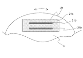
- FIG. 22 is a side view showing a brake lining 21 and a brake disc 4 according to Embodiment 9 of the present invention.
- the brake lining 21 is composed of a lining body 21a and a plurality of (two in this case) linear high hardness portions 21b having a hardness higher than that of the lining body 21a.
- the high hardness portion 19b of the seventh embodiment is provided over the entire length in the length direction of the brake lining 19, but the high hardness portion 21b of the ninth embodiment has both end portions in the length direction of the brake lining 21. Is provided only in a part in the length direction, here, in the vicinity of the central portion. Other configurations and manufacturing methods are the same as those in the seventh embodiment.
- Such a brake lining 21 can provide a brake device that can improve the wear resistance and can secure a stable braking force against environmental changes.
- the brake device can be reduced in size and weight.
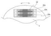
- FIG. 23 is a side view showing a brake lining 22 and a brake disc 4 according to Embodiment 10 of the present invention.
- the brake lining 22 includes a lining body 22a and a plurality of (here, two places) linear high hardness portions 22b having a hardness higher than that of the lining body 22a.
- the high hardness portion 20b of the eighth embodiment is provided over the entire length in the length direction of the brake lining 20, but the high hardness portion 22b of the tenth embodiment is both ends of the brake lining 22 in the length direction. Is provided only in a part in the length direction, here, in the vicinity of the central portion. Other configurations and manufacturing methods are the same as those in the eighth embodiment.
- Such a brake lining 22 can provide a brake device that can improve the wear resistance and can secure a stable braking force against environmental changes.
- the brake device can be reduced in size and weight.
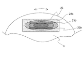
- FIG. 24 is a side view showing the brake lining 23 and the brake disc 4 according to the eleventh embodiment of the present invention.
- the brake lining 23 is composed of a lining body 23a and a plurality of (two in this case) linear high hardness portions 23b having a hardness higher than that of the lining body 23a.
- the hardness of the lining body 23a gradually decreases gradually from the central part in the length direction and the width direction of the brake lining 23 toward the peripheral part.
- the high hardness part 23b is not provided in the both ends of the length direction of the brake lining 23, but is provided only in a part of the length direction, here center part vicinity.
- a brake lining 23 it is possible to provide a brake device that can improve wear resistance and can secure a stable braking force against environmental changes.
- the brake device can be reduced in size and weight.
- a high hardness portion as shown in the seventh to eleventh embodiments may be combined with the brake lining 17 shown in the fifth embodiment.
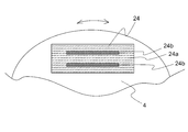
- FIG. 25 is a side view showing a brake lining 24 and a brake disc 4 according to Embodiment 12 of the present invention.
- the brake linings 19 to 23 are each composed of only the same kind of material. However, a brake lining having a hardness distribution can be obtained by combining a plurality of materials.
- the brake lining 24 of the twelfth embodiment includes a high friction portion 24a as a lining body in which a high friction material is mixed and a friction coefficient with respect to the brake disk 4 is increased, and a high hardness made of a material having a higher hardness than the high friction portion 24a.
- the unit 24b is combined.
- the high friction material mixed in the high friction part 24a for example, rubber, urethane, cork, or the like can be used.
- the high hardness portion 24b is exposed in two parallel straight lines.
- the exposed portions of these high hardness portions 24b have the same shape as the high hardness portions 21b, 22b, and 23b of the ninth to eleventh embodiments.
- the high friction part 24a is made of a resin having a high friction coefficient, the high friction part 24a can secure a sufficient braking ability, but is easily worn. For this reason, by providing the high hardness portion 24b near the central portion where the contact surface pressure with the brake disc 4 is high, it is possible to suppress wear of the brake lining 24 and to secure a braking force. Therefore, even if the coefficient of friction is high, the wear resistance is good and a long-life brake device can be obtained.
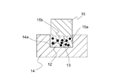
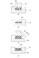
- 26A to 26D are cross-sectional views schematically showing the method for manufacturing the brake lining 24 of FIG. 25 in the order of steps.
- the material of the high hardness portion 24b is put into the die 14, and heated and pressed by the first punch 25 in which a plurality of concave portions 25b are formed on the pressing surface 25a.
- the high hardness portion 24 b is formed at the bottom in the die 14.
- the material of the high friction portion 24a is put into the die 14 from above the molded body of the high hardness portion 24b, and the second punch 26 having the flat pressing surface 26a is used. Heat and pressurize. Thereby, as shown in FIG.26 (d), the molded object which combined the high friction part 24a and the high hardness part 24b is obtained. Finally, the brake lining 24 is taken out from the die 14 and, after firing, is polished to expose the high hardness portion 24b on the surface.
- the brake lining 24 can be manufactured using conventional equipment, a high-quality brake device can be obtained at a low cost.
- the weight and dimensions of the brake device increase when the friction coefficient of the brake lining 24 with respect to the brake disk 4 is small.
- the friction coefficient can be increased. It is possible to increase the margin of the size and reduce the size and weight.
- the shape, number, orientation, etc. of the exposed portion of the high hardness portion 24b can be appropriately changed as in the seventh to eleventh embodiments. Further, the shape of the brake lining in the first to twelfth embodiments is not limited to a rectangle.
Abstract
Priority Applications (5)
| Application Number | Priority Date | Filing Date | Title |
|---|---|---|---|
| JP2012523449A JP5442120B2 (ja) | 2010-07-05 | 2010-07-05 | ブレーキライニング |
| KR1020127032294A KR101442945B1 (ko) | 2010-07-05 | 2010-07-05 | 브레이크 라이닝 및 그 제조방법 |
| EP10854400.8A EP2592299A4 (fr) | 2010-07-05 | 2010-07-05 | Garniture de frein et son procédé de production |
| PCT/JP2010/061385 WO2012004844A1 (fr) | 2010-07-05 | 2010-07-05 | Garniture de frein et son procédé de production |
| CN201080067353.3A CN102933867B (zh) | 2010-07-05 | 2010-07-05 | 一种制动器衬片 |
Applications Claiming Priority (1)
| Application Number | Priority Date | Filing Date | Title |
|---|---|---|---|
| PCT/JP2010/061385 WO2012004844A1 (fr) | 2010-07-05 | 2010-07-05 | Garniture de frein et son procédé de production |
Publications (1)
| Publication Number | Publication Date |
|---|---|
| WO2012004844A1 true WO2012004844A1 (fr) | 2012-01-12 |
Family
ID=45440846
Family Applications (1)
| Application Number | Title | Priority Date | Filing Date |
|---|---|---|---|
| PCT/JP2010/061385 WO2012004844A1 (fr) | 2010-07-05 | 2010-07-05 | Garniture de frein et son procédé de production |
Country Status (5)
| Country | Link |
|---|---|
| EP (1) | EP2592299A4 (fr) |
| JP (1) | JP5442120B2 (fr) |
| KR (1) | KR101442945B1 (fr) |
| CN (1) | CN102933867B (fr) |
| WO (1) | WO2012004844A1 (fr) |
Cited By (3)
| Publication number | Priority date | Publication date | Assignee | Title |
|---|---|---|---|---|
| WO2013034263A1 (fr) | 2011-09-09 | 2013-03-14 | Paul Hartmann Ag | Pansement abdominal comprenant un dispositif d'aide à l'application |
| WO2014203889A1 (fr) * | 2013-06-18 | 2014-12-24 | 曙ブレーキ工業株式会社 | Moule pour matériel à friction pour plaquette de frein, dispositif de fabrication, procédé de fabrication, préforme et plaquette de frein |
| JPWO2018229995A1 (ja) * | 2017-06-16 | 2019-11-07 | 三菱電機株式会社 | ブレーキライニング |
Families Citing this family (5)
| Publication number | Priority date | Publication date | Assignee | Title |
|---|---|---|---|---|
| CN106255837B (zh) * | 2014-04-29 | 2019-09-13 | 保罗·A·斯特凡努蒂 | 摩擦材料和形成摩擦材料的方法 |
| CN104632959B (zh) * | 2014-12-09 | 2017-12-19 | 厦门市双晋材料科技有限公司 | 一种制备刹车片的新型模具和工艺 |
| DE102015107562B4 (de) * | 2015-05-13 | 2017-06-22 | Tmd Friction Services Gmbh | Verfahren zur Herstellung einer Bremsbacke, Presse zur Herstellung von Bremsbacken sowie Bremsbacke |
| JP6567190B2 (ja) * | 2016-07-26 | 2019-08-28 | 三菱電機株式会社 | ブレーキのライニング |
| KR20230106319A (ko) | 2022-01-06 | 2023-07-13 | (주) 삼성특수브레이크 | 교체가능한 드릴헤드를 포함하는 브레이크 라이닝 성형장치 및 이의 제어방법 |
Citations (10)
| Publication number | Priority date | Publication date | Assignee | Title |
|---|---|---|---|---|
| JPS59108835U (ja) * | 1983-01-12 | 1984-07-23 | 日清紡績株式会社 | 摩擦制動体 |
| JPS6035930U (ja) * | 1983-08-20 | 1985-03-12 | トキコ株式会社 | デイスクブレ−キ用摩擦パツド |
| JPS61184232A (ja) * | 1985-02-06 | 1986-08-16 | Toyota Motor Corp | デイスクブレ−キ |
| JPH04114084A (ja) * | 1990-09-01 | 1992-04-15 | Sumitomo Electric Ind Ltd | ディスクブレーキ用摩擦材 |
| JPH0989023A (ja) * | 1995-09-29 | 1997-03-31 | Hitachi Chem Co Ltd | ディスクブレーキパッドの製造法 |
| JPH10274266A (ja) * | 1997-03-31 | 1998-10-13 | Hitachi Chem Co Ltd | ディスクブレーキパッドの製造法 |
| JPH11303913A (ja) * | 1998-04-22 | 1999-11-02 | Nisshinbo Ind Inc | 摩擦部材用金型、摩擦材仮成形品用金型、摩擦部材の製造方法及び摩擦材仮成形品の製造方法 |
| JP2001181064A (ja) | 1999-12-27 | 2001-07-03 | Unitika Ltd | 炭素繊維強化炭素複合材用成形体及び炭素繊維強化炭素複合材並びにその製造方法 |
| JP2003021181A (ja) | 2001-07-06 | 2003-01-24 | Sumitomo Denko Brake Systems Kk | ディスクブレーキ用摩擦パッド |
| JP2003194121A (ja) | 2001-12-27 | 2003-07-09 | Tokico Ltd | ブレーキ摩擦材 |
Family Cites Families (6)
| Publication number | Priority date | Publication date | Assignee | Title |
|---|---|---|---|---|
| DE2754185A1 (de) * | 1977-12-06 | 1979-06-07 | Knorr Bremse Gmbh | Bremsbelag fuer bremsbacken von scheibenbremsen |
| JPH02134426A (ja) * | 1988-11-11 | 1990-05-23 | Nisshinbo Ind Inc | 摩擦材及びその製造方法 |
| JPH0642944U (ja) * | 1992-11-18 | 1994-06-07 | 日立化成工業株式会社 | 摩擦材 |
| US5413194A (en) * | 1994-07-25 | 1995-05-09 | Pneumo Abex Corporation | Brake friction pad assembly |
| JP2002181091A (ja) * | 2000-12-11 | 2002-06-26 | Sumitomo Denko Brake Systems Kk | 摩擦材アセンブリ |
| US7207424B2 (en) * | 2002-12-03 | 2007-04-24 | Ucar Carbon Company Inc. | Manufacture of carbon/carbon composites by hot pressing |
-
2010
- 2010-07-05 KR KR1020127032294A patent/KR101442945B1/ko active IP Right Grant
- 2010-07-05 CN CN201080067353.3A patent/CN102933867B/zh not_active Expired - Fee Related
- 2010-07-05 JP JP2012523449A patent/JP5442120B2/ja not_active Expired - Fee Related
- 2010-07-05 EP EP10854400.8A patent/EP2592299A4/fr not_active Withdrawn
- 2010-07-05 WO PCT/JP2010/061385 patent/WO2012004844A1/fr active Application Filing
Patent Citations (10)
| Publication number | Priority date | Publication date | Assignee | Title |
|---|---|---|---|---|
| JPS59108835U (ja) * | 1983-01-12 | 1984-07-23 | 日清紡績株式会社 | 摩擦制動体 |
| JPS6035930U (ja) * | 1983-08-20 | 1985-03-12 | トキコ株式会社 | デイスクブレ−キ用摩擦パツド |
| JPS61184232A (ja) * | 1985-02-06 | 1986-08-16 | Toyota Motor Corp | デイスクブレ−キ |
| JPH04114084A (ja) * | 1990-09-01 | 1992-04-15 | Sumitomo Electric Ind Ltd | ディスクブレーキ用摩擦材 |
| JPH0989023A (ja) * | 1995-09-29 | 1997-03-31 | Hitachi Chem Co Ltd | ディスクブレーキパッドの製造法 |
| JPH10274266A (ja) * | 1997-03-31 | 1998-10-13 | Hitachi Chem Co Ltd | ディスクブレーキパッドの製造法 |
| JPH11303913A (ja) * | 1998-04-22 | 1999-11-02 | Nisshinbo Ind Inc | 摩擦部材用金型、摩擦材仮成形品用金型、摩擦部材の製造方法及び摩擦材仮成形品の製造方法 |
| JP2001181064A (ja) | 1999-12-27 | 2001-07-03 | Unitika Ltd | 炭素繊維強化炭素複合材用成形体及び炭素繊維強化炭素複合材並びにその製造方法 |
| JP2003021181A (ja) | 2001-07-06 | 2003-01-24 | Sumitomo Denko Brake Systems Kk | ディスクブレーキ用摩擦パッド |
| JP2003194121A (ja) | 2001-12-27 | 2003-07-09 | Tokico Ltd | ブレーキ摩擦材 |
Non-Patent Citations (1)
| Title |
|---|
| See also references of EP2592299A4 * |
Cited By (5)
| Publication number | Priority date | Publication date | Assignee | Title |
|---|---|---|---|---|
| WO2013034263A1 (fr) | 2011-09-09 | 2013-03-14 | Paul Hartmann Ag | Pansement abdominal comprenant un dispositif d'aide à l'application |
| WO2014203889A1 (fr) * | 2013-06-18 | 2014-12-24 | 曙ブレーキ工業株式会社 | Moule pour matériel à friction pour plaquette de frein, dispositif de fabrication, procédé de fabrication, préforme et plaquette de frein |
| CN105307846A (zh) * | 2013-06-18 | 2016-02-03 | 曙制动器工业株式会社 | 刹车垫摩擦材料的模具、生产设备、生产方法、预成型体和刹车垫 |
| US10144189B2 (en) | 2013-06-18 | 2018-12-04 | Akebono Brake Industry Co., Ltd. | Mold for brake pad friction material, manufacturing apparatus, manufacturing method, preform, and brake pad |
| JPWO2018229995A1 (ja) * | 2017-06-16 | 2019-11-07 | 三菱電機株式会社 | ブレーキライニング |
Also Published As
| Publication number | Publication date |
|---|---|
| JP5442120B2 (ja) | 2014-03-12 |
| KR20130018319A (ko) | 2013-02-20 |
| EP2592299A4 (fr) | 2018-06-13 |
| EP2592299A1 (fr) | 2013-05-15 |
| KR101442945B1 (ko) | 2014-09-23 |
| JPWO2012004844A1 (ja) | 2013-09-02 |
| CN102933867B (zh) | 2016-03-02 |
| CN102933867A (zh) | 2013-02-13 |
Similar Documents
| Publication | Publication Date | Title |
|---|---|---|
| JP5442120B2 (ja) | ブレーキライニング | |
| JP5627042B2 (ja) | ブレーキライニング及びその製造方法 | |
| EP1886962B1 (fr) | Appareil de levage pour ascenseur | |
| JP5436684B2 (ja) | ブレーキ装置、ブレーキライニング、ブレーキライニングの製造方法及びエレベータ装置 | |
| JP2009513909A (ja) | 駐車ブレーキ | |
| JP4834095B2 (ja) | 自己増幅型の電気機械式ディスクブレーキ | |
| JP5495811B2 (ja) | エレベータの巻上機ブレーキ | |
| JP2015155348A (ja) | エレベータ及びその巻上機 | |
| JP6697792B2 (ja) | エレベータの巻上機ブレーキ及びエレベータ巻上機 | |
| KR20160142847A (ko) | 범용 심을 가진 브레이크 패드 조립체 | |
| JP2006193292A (ja) | エレベータ用巻上機 | |
| JP7092805B2 (ja) | 電磁ブレーキ装置、巻上機及びエレベーター | |
| KR20100035258A (ko) | 주차 브레이크용 드럼과 디스크 브레이크용 디스크 로터가 일체로 형성된 dih 구조의 브레이크 디스크 | |
| JP2010255773A (ja) | ディスクブレーキ用パッドおよびその製造方法 | |
| JP5765944B2 (ja) | ブレーキライニング、及びブレーキライニングの製造方法 | |
| JP2004125081A (ja) | ディスクブレーキパッド | |
| JP6732125B2 (ja) | ブレーキライニング | |
| JP5335736B2 (ja) | 電磁ディスクブレーキ | |
| JPH11303913A (ja) | 摩擦部材用金型、摩擦材仮成形品用金型、摩擦部材の製造方法及び摩擦材仮成形品の製造方法 | |
| JP2003146564A (ja) | エレベータ用ブレーキ | |
| JP2011202705A (ja) | 電磁ディスクブレーキ | |
| JPH0547296Y2 (fr) | ||
| JP2008274194A (ja) | 摩擦部材およびブレーキパッド | |
| JP2012017779A (ja) | 電磁ディスクブレーキ |
Legal Events
| Date | Code | Title | Description |
|---|---|---|---|
| WWE | Wipo information: entry into national phase |
Ref document number: 201080067353.3 Country of ref document: CN |
|
| 121 | Ep: the epo has been informed by wipo that ep was designated in this application |
Ref document number: 10854400 Country of ref document: EP Kind code of ref document: A1 |
|
| WWE | Wipo information: entry into national phase |
Ref document number: 2012523449 Country of ref document: JP |
|
| WWE | Wipo information: entry into national phase |
Ref document number: 2010854400 Country of ref document: EP |
|
| ENP | Entry into the national phase |
Ref document number: 20127032294 Country of ref document: KR Kind code of ref document: A |
|
| NENP | Non-entry into the national phase |
Ref country code: DE |