WO2011132755A1 - 配線材 - Google Patents
配線材 Download PDFInfo
- Publication number
- WO2011132755A1 WO2011132755A1 PCT/JP2011/059873 JP2011059873W WO2011132755A1 WO 2011132755 A1 WO2011132755 A1 WO 2011132755A1 JP 2011059873 W JP2011059873 W JP 2011059873W WO 2011132755 A1 WO2011132755 A1 WO 2011132755A1
- Authority
- WO
- WIPO (PCT)
- Prior art keywords
- wiring
- wiring material
- battery
- straight
- terminals
- Prior art date
- Legal status (The legal status is an assumption and is not a legal conclusion. Google has not performed a legal analysis and makes no representation as to the accuracy of the status listed.)
- Ceased
Links
Images




Classifications
-
- H—ELECTRICITY
- H01—ELECTRIC ELEMENTS
- H01M—PROCESSES OR MEANS, e.g. BATTERIES, FOR THE DIRECT CONVERSION OF CHEMICAL ENERGY INTO ELECTRICAL ENERGY
- H01M50/00—Constructional details or processes of manufacture of the non-active parts of electrochemical cells other than fuel cells, e.g. hybrid cells
- H01M50/50—Current conducting connections for cells or batteries
- H01M50/502—Interconnectors for connecting terminals of adjacent batteries; Interconnectors for connecting cells outside a battery casing
-
- H—ELECTRICITY
- H01—ELECTRIC ELEMENTS
- H01M—PROCESSES OR MEANS, e.g. BATTERIES, FOR THE DIRECT CONVERSION OF CHEMICAL ENERGY INTO ELECTRICAL ENERGY
- H01M50/00—Constructional details or processes of manufacture of the non-active parts of electrochemical cells other than fuel cells, e.g. hybrid cells
- H01M50/20—Mountings; Secondary casings or frames; Racks, modules or packs; Suspension devices; Shock absorbers; Transport or carrying devices; Holders
- H01M50/204—Racks, modules or packs for multiple batteries or multiple cells
-
- H—ELECTRICITY
- H01—ELECTRIC ELEMENTS
- H01M—PROCESSES OR MEANS, e.g. BATTERIES, FOR THE DIRECT CONVERSION OF CHEMICAL ENERGY INTO ELECTRICAL ENERGY
- H01M50/00—Constructional details or processes of manufacture of the non-active parts of electrochemical cells other than fuel cells, e.g. hybrid cells
- H01M50/50—Current conducting connections for cells or batteries
- H01M50/502—Interconnectors for connecting terminals of adjacent batteries; Interconnectors for connecting cells outside a battery casing
- H01M50/503—Interconnectors for connecting terminals of adjacent batteries; Interconnectors for connecting cells outside a battery casing characterised by the shape of the interconnectors
-
- H—ELECTRICITY
- H01—ELECTRIC ELEMENTS
- H01M—PROCESSES OR MEANS, e.g. BATTERIES, FOR THE DIRECT CONVERSION OF CHEMICAL ENERGY INTO ELECTRICAL ENERGY
- H01M50/00—Constructional details or processes of manufacture of the non-active parts of electrochemical cells other than fuel cells, e.g. hybrid cells
- H01M50/50—Current conducting connections for cells or batteries
- H01M50/502—Interconnectors for connecting terminals of adjacent batteries; Interconnectors for connecting cells outside a battery casing
- H01M50/507—Interconnectors for connecting terminals of adjacent batteries; Interconnectors for connecting cells outside a battery casing comprising an arrangement of two or more busbars within a container structure, e.g. busbar modules
-
- H—ELECTRICITY
- H01—ELECTRIC ELEMENTS
- H01M—PROCESSES OR MEANS, e.g. BATTERIES, FOR THE DIRECT CONVERSION OF CHEMICAL ENERGY INTO ELECTRICAL ENERGY
- H01M50/00—Constructional details or processes of manufacture of the non-active parts of electrochemical cells other than fuel cells, e.g. hybrid cells
- H01M50/50—Current conducting connections for cells or batteries
- H01M50/502—Interconnectors for connecting terminals of adjacent batteries; Interconnectors for connecting cells outside a battery casing
- H01M50/521—Interconnectors for connecting terminals of adjacent batteries; Interconnectors for connecting cells outside a battery casing characterised by the material
- H01M50/522—Inorganic material
-
- Y—GENERAL TAGGING OF NEW TECHNOLOGICAL DEVELOPMENTS; GENERAL TAGGING OF CROSS-SECTIONAL TECHNOLOGIES SPANNING OVER SEVERAL SECTIONS OF THE IPC; TECHNICAL SUBJECTS COVERED BY FORMER USPC CROSS-REFERENCE ART COLLECTIONS [XRACs] AND DIGESTS
- Y02—TECHNOLOGIES OR APPLICATIONS FOR MITIGATION OR ADAPTATION AGAINST CLIMATE CHANGE
- Y02E—REDUCTION OF GREENHOUSE GAS [GHG] EMISSIONS, RELATED TO ENERGY GENERATION, TRANSMISSION OR DISTRIBUTION
- Y02E60/00—Enabling technologies; Technologies with a potential or indirect contribution to GHG emissions mitigation
- Y02E60/10—Energy storage using batteries
Definitions
- the present invention relates to a wiring material connected to a battery mounted on a vehicle such as an electric vehicle or a hybrid car.
- Electric cars and hybrid cars are increasing as environmentally friendly cars.
- a power supply device including a battery assembly in which a plurality of batteries are stacked.
- this type of power supply device has a printed circuit board composed of a hard circuit board that is connected to each battery and wired with a signal output line for outputting the battery voltage to the outside.
- a board and a bus bar for wiring fixed to a battery terminal are connected by a connection terminal (see, for example, Patent Document 1).
- the wiring member has a straight line portion extending along the battery arrangement and a branch line portion that branches from the straight line portion to the bus bar of each battery.
- This invention is made
- the objective is to provide the wiring material which can suppress the influence by the shift
- a wiring member made of a flexible printed wiring board connected to a plurality of battery terminals, a linear portion arranged along the array of the aligned terminals, and each terminal from the linear portion
- a plurality of branch line portions extending and connected to the connection position, and the branch line portion has a flexible portion that can be deformed in response to displacement in the longitudinal direction of the straight line portion.
- the straight line portion extends from the straight line portion arranged along the arrangement of the terminals of the plurality of aligned batteries toward the respective terminals and is connected to the terminals. Since a deformable bending part is provided corresponding to the displacement in the longitudinal direction, even if the dimensional tolerance in the external dimensions of the battery accumulates and a deviation occurs in the connection position of the branch line part, the deviation is reduced. It can be absorbed by deformation of the flexure. As a result, it is possible to eliminate the problem that the wiring member is twisted due to the displacement of the connection position and an excessive force is applied, and a good wiring state can be maintained with high reliability.
- the second bent portion that deforms corresponding to the expansion and contraction in the longitudinal direction of the straight portion is provided in the straight portion, the second bent portion also deforms in this straight portion.
- the displacement of the connection position to the terminal can be further absorbed, and a good wiring state can be reliably maintained.
- the second bent portion is formed by inserting a plurality of holes opened in the linear portion at a pitch wider than the pitch of the protrusions into a plurality of protrusions protruding at a predetermined pitch on a plate attached to the battery. To be formed.
- the second protrusion can be obtained by simply inserting a plurality of holes opened in the linear portion at a pitch wider than the pitch of the protrusions into a plurality of protrusions protruding at a predetermined pitch on a plate such as a battery connection plate. Therefore, it is possible to obtain a wiring material capable of absorbing the displacement of the connection position to the terminal at a very low cost.
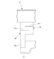
- FIG. 6 (a) and 6 (b) are enlarged plan views showing a bent state in the branch line portion of the wiring member shown in FIG. 4, and FIG. 6 (a) shows a state in which the straight portion is displaced in the direction of arrow A.
- FIG. 6B shows a state where the straight line portion is displaced in the direction of arrow C.
- FIG. 6 shows a top view which shows the wiring material which concerns on a reference example.
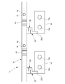
- a wiring member 11 is attached to a battery connection plate (plate) 12.
- the battery connection plate 12 is formed from a synthetic resin, and a plurality of bus bar mounting portions 13 are formed on both the left and right sides.
- a bus bar 14 made of a metal plate is fitted into these bus bar mounting portions 13.
- a pair of connection holes 14a is formed in these bus bars 14, and terminals of a plurality of batteries (not shown) arranged in an overlapping manner are inserted into these connection holes 14a. Then, by fastening a nut to the terminal of the battery, the terminal is connected to the bus bar 14 in a conductive state.
- the battery connection plate 12 is provided with a wiring material mounting portion 15 along the bus bar mounting portion 13, and the wiring material 11 is mounted on the wiring material mounting portion 15.
- the wiring member 11 is made of a flexible printed circuit board (FPC), and is provided on the battery connection plate 12 as a wiring for battery voltage detection.
- the wiring member 11 includes a straight line portion 21 arranged along the battery terminal arrangement, and a plurality of branch line portions 22 extending laterally from the straight line portion 21. And have. And each branch line part 22 of this wiring material 11 is connected to each bus bar 14 at a connection end 22 a formed from the tip thereof, and is thereby electrically connected to the battery terminal via the bus bar 14.
- the branch line portion 22 is formed into an S shape in plan view by alternately forming the cut portions 31 a and 31 b along the longitudinal direction from the width direction (left and right direction).
- the S-shaped portion is a bent portion 32.
- this bending part 32 can be deform
- the bent portion 32 of the branch line portion 22 has a portion on the connection end 22a side of the cut portion 31a (FIG. 6A).
- the deviation is absorbed by the middle B portion) being curved in a direction intersecting the surface.
- FIG. 6B when the straight portion 21 is displaced in the direction of the arrow C, in the bent portion 32 of the branch line portion 22, the portion on the connection end 22a side of the cut portion 31b (in FIG. 6B) The deviation is absorbed by the curve in the direction in which the portion D) intersects the surface.
- the wiring material mounting portion 15 of the battery connection plate 12 is provided with a plurality of protrusions 41 formed with a predetermined pitch.
- a plurality of hole portions 42 are formed in the linear portion 21 of the wiring member 11, and the protrusion 41 of the battery connection plate 12 is inserted into these hole portions 42.
- the pitch of the holes 42 of the wiring member 11 is wider than the predetermined pitch of the protrusions 41 of the battery connection plate 12.
- the wiring members 11 extend from the straight portions 21 arranged along the array of the arranged battery terminals toward the respective terminals, and pass through the bus bars 14.
- the plurality of branch line portions 22 connected to the terminals are provided with the flexible portions 32 that can be deformed corresponding to the displacement of the straight portion 21 in the longitudinal direction. Even if a deviation occurs in the connection position of the branch line portion 22 to the terminal due to accumulation, the deflection portion 32 can be deformed and absorbed. Thereby, the malfunction that an excessive force acts on the wiring material 11 by the shift
- the second bending portion 43 that is deformed corresponding to the expansion and contraction in the longitudinal direction of the straight portion 21 is provided in the straight portion 21, the second bending portion 43 is also deformed in the straight portion 21. Therefore, it is possible to absorb the shift of the connection position to the battery terminal and to reliably maintain a good wiring state.
- the plurality of protrusions 41 protruding from the battery connection plate 12 at a predetermined pitch are simply inserted into the plurality of holes 42 opened in the linear portion 21 at a pitch wider than the pitch of the protrusions 41, so that the second Since the bending part 43 can be formed, the wiring material 11 which can absorb the shift
- FIG. 7 shows a wiring member 111 according to a reference example.
- the wiring member 111 is formed from a flexible printed wiring board, but the branch line portion 122 does not have a portion corresponding to the bent portion 32 of the above embodiment, and a straight portion. 121 does not have a portion corresponding to the second bending portion 43 of the above embodiment.
- the flexible printed wiring board is easy to bend in the direction intersecting the plane, but is difficult to deform in the plane direction. Therefore, as described above, if a twisting force or a pulling force acts due to a bending force in the surface direction, an excessive force acts on the wiring pattern of the flexible printed wiring board, and it is difficult to maintain a good wiring state. There is a risk.
- this invention is not limited to embodiment mentioned above, A deformation
- the material, shape, dimensions, number, arrangement location, and the like of each component in the above-described embodiment are arbitrary and are not limited as long as the present invention can be achieved.
- the second bent portion of the linear portion is realized by engaging the protrusion formed on the wiring material mounting portion with the hole of the wiring material, but a predetermined portion of the wiring material is processed. It can also be formed by bending in advance by molding.
- the wiring material according to the present invention even if the dimensional tolerances in the external dimensions of the plurality of batteries accumulate and the connecting position to the terminal of the branch line portion shifts, the wiring material is twisted due to the shift, which is impossible. It is possible to eliminate the problem that force acts, and to maintain a good wiring state with high reliability.
Landscapes
- Chemical & Material Sciences (AREA)
- Chemical Kinetics & Catalysis (AREA)
- Electrochemistry (AREA)
- General Chemical & Material Sciences (AREA)
- Connection Of Batteries Or Terminals (AREA)
- Battery Mounting, Suspending (AREA)
Abstract
Description
(1) 複数のバッテリの端子に接続されるフレキシブルプリント配線基板からなる配線材であって、整列された前記端子の配列に沿って配置される直線部と、前記直線部からそれぞれの前記端子との接続位置へ向かって延出して接続される複数の分岐線部とを有し、前記分岐線部は、前記直線部の長手方向への変位に対応して変形可能な撓み部を有すること。
前記直線部の長手方向の伸縮に対応して変形する第2の撓み部が、前記直線部に設けられていること。
前記第2の撓み部は、前記バッテリに取り付けられるプレートに所定ピッチで突設した複数の突起に、前記突起のピッチよりも広いピッチで前記直線部に開口した複数の穴部を挿入することにより形成されること。
図1及び図2に示すように、本発明の一実施形態に係る配線材11は、バッテリ接続プレート(プレート)12に装着される。このバッテリ接続プレート12は、合成樹脂から成形されたもので、左右両側に、複数のバスバー装着部13が形成されている。これらのバスバー装着部13には、金属板からなるバスバー14が嵌め込まれている。これらのバスバー14には、一対の接続孔14aが形成されており、これらの接続孔14aには、重ね合わせて配置された複数のバッテリ(図示略)の端子が挿入される。そして、このバッテリの端子にナットを締結することにより、端子がバスバー14と導通した状態に接続される。
配線材11は、フレキシブルプリント配線基板(FPC)からなるもので、バッテリの電圧検出用の配線としてバッテリ接続プレート12に設けられている。
図7に示すように、この配線材111は、フレキシブルプリント配線基板から形成されたものであるが、分岐線部122に、上記実施形態の撓み部32に相当する部分がなく、また、直線部121にも、上記実施形態の第2の撓み部43に相当する部分がないものである。
例えば、上述した実施形態では、直線部の第2の撓み部を、配線材装着部に形成した突起を、配線材の穴部に係合させて実現するとしたが、配線材の所定箇所を加工成形により予め湾曲状に撓ませて形成することもできる。
12 バッテリ接続プレート(プレート)
21 直線部
22 分岐線部
32 撓み部
41 突起
42 穴部
43 第2の撓み部
Claims (3)
- 複数のバッテリの端子に接続されるフレキシブルプリント配線基板からなる配線材であって、
整列された前記端子の配列に沿って配置される直線部と、
前記直線部からそれぞれの前記端子との接続位置へ向かって延出して接続される複数の分岐線部とを有し、
前記分岐線部は、前記直線部の長手方向への変位に対応して変形可能な撓み部を有する配線材。 - 前記直線部の長手方向の伸縮に対応して変形する第2の撓み部が、前記直線部に設けられている請求項1に記載の配線材。
- 前記第2の撓み部は、前記バッテリに取り付けられるプレートに所定ピッチで突設した複数の突起に、前記突起のピッチよりも広いピッチで前記直線部に開口した複数の穴部を挿入することにより形成される請求項2に記載の配線材。
Priority Applications (3)
| Application Number | Priority Date | Filing Date | Title |
|---|---|---|---|
| US13/502,953 US8777668B2 (en) | 2010-04-22 | 2011-04-21 | Wiring member |
| DE112011101412.0T DE112011101412B4 (de) | 2010-04-22 | 2011-04-21 | Verdrahtungsglied |
| CN201180004258.3A CN102576845B (zh) | 2010-04-22 | 2011-04-21 | 配线部件 |
Applications Claiming Priority (2)
| Application Number | Priority Date | Filing Date | Title |
|---|---|---|---|
| JP2010-099194 | 2010-04-22 | ||
| JP2010099194A JP5702947B2 (ja) | 2010-04-22 | 2010-04-22 | 配線材 |
Publications (1)
| Publication Number | Publication Date |
|---|---|
| WO2011132755A1 true WO2011132755A1 (ja) | 2011-10-27 |
Family
ID=44834270
Family Applications (1)
| Application Number | Title | Priority Date | Filing Date |
|---|---|---|---|
| PCT/JP2011/059873 Ceased WO2011132755A1 (ja) | 2010-04-22 | 2011-04-21 | 配線材 |
Country Status (5)
| Country | Link |
|---|---|
| US (1) | US8777668B2 (ja) |
| JP (1) | JP5702947B2 (ja) |
| CN (1) | CN102576845B (ja) |
| DE (1) | DE112011101412B4 (ja) |
| WO (1) | WO2011132755A1 (ja) |
Cited By (1)
| Publication number | Priority date | Publication date | Assignee | Title |
|---|---|---|---|---|
| CN114556682A (zh) * | 2019-10-29 | 2022-05-27 | 株式会社自动网络技术研究所 | 布线模块 |
Families Citing this family (86)
| Publication number | Priority date | Publication date | Assignee | Title |
|---|---|---|---|---|
| JP5702947B2 (ja) | 2010-04-22 | 2015-04-15 | 矢崎総業株式会社 | 配線材 |
| JP5570383B2 (ja) * | 2010-10-15 | 2014-08-13 | 株式会社神戸製鋼所 | 導電性連結部材、導電性連結部材の製造方法、及び導電性連結部材が電極とされたバッテリ |
| JP5772525B2 (ja) * | 2011-11-11 | 2015-09-02 | 株式会社オートネットワーク技術研究所 | 電池配線モジュール |
| JP5826637B2 (ja) * | 2012-01-11 | 2015-12-02 | 愛三工業株式会社 | 電池モジュール |
| US8895865B2 (en) * | 2012-09-07 | 2014-11-25 | Conor P. Lenahan | Conductive connections allowing XYZ translation |
| JP6040728B2 (ja) * | 2012-11-21 | 2016-12-07 | Tdk株式会社 | ブスバー基板及びブスバー基板を用いた電池モジュール |
| US9270795B2 (en) | 2012-12-18 | 2016-02-23 | Panasonic Intellectual Property Management Co., Ltd. | Communication antenna unit and mobile terminal apparatus |
| JP5421449B1 (ja) * | 2012-12-18 | 2014-02-19 | パナソニック株式会社 | 携帯端末装置 |
| US10528135B2 (en) | 2013-01-14 | 2020-01-07 | Ctrl-Labs Corporation | Wearable muscle interface systems, devices and methods that interact with content displayed on an electronic display |
| WO2014125642A1 (ja) * | 2013-02-18 | 2014-08-21 | 日立ビークルエナジー株式会社 | 電池ブロック及び二次電池モジュール |
| US10152082B2 (en) | 2013-05-13 | 2018-12-11 | North Inc. | Systems, articles and methods for wearable electronic devices that accommodate different user forms |
| JP6186922B2 (ja) * | 2013-06-18 | 2017-08-30 | 住友電装株式会社 | 配線モジュール |
| US10042422B2 (en) | 2013-11-12 | 2018-08-07 | Thalmic Labs Inc. | Systems, articles, and methods for capacitive electromyography sensors |
| US12504816B2 (en) | 2013-08-16 | 2025-12-23 | Meta Platforms Technologies, Llc | Wearable devices and associated band structures for sensing neuromuscular signals using sensor pairs in respective pods with communicative pathways to a common processor |
| US10188309B2 (en) | 2013-11-27 | 2019-01-29 | North Inc. | Systems, articles, and methods for electromyography sensors |
| US20150124566A1 (en) | 2013-10-04 | 2015-05-07 | Thalmic Labs Inc. | Systems, articles and methods for wearable electronic devices employing contact sensors |
| US11426123B2 (en) | 2013-08-16 | 2022-08-30 | Meta Platforms Technologies, Llc | Systems, articles and methods for signal routing in wearable electronic devices that detect muscle activity of a user using a set of discrete and separately enclosed pod structures |
| US11921471B2 (en) | 2013-08-16 | 2024-03-05 | Meta Platforms Technologies, Llc | Systems, articles, and methods for wearable devices having secondary power sources in links of a band for providing secondary power in addition to a primary power source |
| US9788789B2 (en) * | 2013-08-30 | 2017-10-17 | Thalmic Labs Inc. | Systems, articles, and methods for stretchable printed circuit boards |
| US9831482B2 (en) * | 2013-09-06 | 2017-11-28 | Johnson Controls Technology Company | Battery module lid system and method |
| JP6198061B2 (ja) * | 2013-10-28 | 2017-09-20 | 株式会社オートネットワーク技術研究所 | 配線モジュール |
| JP6271218B2 (ja) * | 2013-11-01 | 2018-01-31 | 矢崎総業株式会社 | 電池配線モジュール |
| WO2015099066A1 (ja) * | 2013-12-25 | 2015-07-02 | 矢崎総業株式会社 | 電池配線モジュール |
| JP6164489B2 (ja) * | 2014-01-21 | 2017-07-19 | 株式会社オートネットワーク技術研究所 | 配線モジュール |
| JP5949796B2 (ja) * | 2014-01-22 | 2016-07-13 | トヨタ自動車株式会社 | 接続ユニット |
| US10199008B2 (en) | 2014-03-27 | 2019-02-05 | North Inc. | Systems, devices, and methods for wearable electronic devices as state machines |
| US9281673B2 (en) * | 2014-04-03 | 2016-03-08 | Ford Global Technologies, Llc | Deformable busbar assembly and bus bar installation method |
| US9880632B2 (en) | 2014-06-19 | 2018-01-30 | Thalmic Labs Inc. | Systems, devices, and methods for gesture identification |
| JP6426945B2 (ja) | 2014-08-27 | 2018-11-21 | 株式会社Gsユアサ | 蓄電装置 |
| US9807221B2 (en) | 2014-11-28 | 2017-10-31 | Thalmic Labs Inc. | Systems, devices, and methods effected in response to establishing and/or terminating a physical communications link |
| JP6245159B2 (ja) * | 2014-12-17 | 2017-12-13 | 株式会社オートネットワーク技術研究所 | 電池配線モジュール |
| US10078435B2 (en) | 2015-04-24 | 2018-09-18 | Thalmic Labs Inc. | Systems, methods, and computer program products for interacting with electronically displayed presentation materials |
| CN106531945B (zh) * | 2015-09-12 | 2023-04-18 | 宁德时代新能源科技股份有限公司 | 并联电池模组 |
| US9564984B1 (en) * | 2015-10-05 | 2017-02-07 | Htc Corporation | Portable electronic device |
| CN108140765B (zh) * | 2016-03-02 | 2020-10-27 | 宁德时代新能源科技股份有限公司 | 电池模组 |
| TW201731603A (zh) * | 2016-03-02 | 2017-09-16 | Dijiya Energy Saving Tech Inc | 鋰電池之導電連接片及其成型方法 |
| US12554325B2 (en) | 2016-07-25 | 2026-02-17 | Meta Platforms Technologies, Llc | Methods and apparatuses for low latency body state prediction based on neuromuscular data |
| WO2018022602A1 (en) | 2016-07-25 | 2018-02-01 | Ctrl-Labs Corporation | Methods and apparatus for predicting musculo-skeletal position information using wearable autonomous sensors |
| US11216069B2 (en) | 2018-05-08 | 2022-01-04 | Facebook Technologies, Llc | Systems and methods for improved speech recognition using neuromuscular information |
| EP3491700A4 (en) * | 2016-07-29 | 2020-06-10 | Hatch Ltd. | FLEXIBLE ELECTRICAL CONNECTORS FOR ELECTROLYTIC CELLS |
| JP6434468B2 (ja) * | 2016-09-30 | 2018-12-05 | 株式会社オートネットワーク技術研究所 | 接続モジュール |
| JP6469062B2 (ja) * | 2016-09-30 | 2019-02-13 | 株式会社オートネットワーク技術研究所 | 接続モジュール |
| CN108155506A (zh) * | 2016-12-06 | 2018-06-12 | 泰科电子(上海)有限公司 | 连接件、连接组件及电池模组 |
| US11376969B2 (en) | 2016-12-27 | 2022-07-05 | Yura Corporation Co., Ltd. | Bus bar assembly and frame assembly |
| EP3379608B1 (en) | 2017-03-23 | 2020-04-22 | TE Connectivity Germany GmbH | Connection assembly for a traction battery in particular for electric vehicles |
| CN109301634B (zh) * | 2017-07-24 | 2020-06-19 | 莫仕连接器(成都)有限公司 | 电池连接模块 |
| JP6946837B2 (ja) * | 2017-08-10 | 2021-10-13 | 株式会社豊田自動織機 | 電池パック |
| US10615396B2 (en) * | 2017-09-08 | 2020-04-07 | Molex, Llc | Battery connection module |
| EP3697297A4 (en) | 2017-10-19 | 2020-12-16 | Facebook Technologies, Inc. | SYSTEMS AND PROCEDURES FOR IDENTIFICATION OF BIOLOGICAL STRUCTURES IN CONNECTION WITH SIGNALS OF NEUROMUSCULAR ORIGIN |
| US11493993B2 (en) | 2019-09-04 | 2022-11-08 | Meta Platforms Technologies, Llc | Systems, methods, and interfaces for performing inputs based on neuromuscular control |
| US11907423B2 (en) | 2019-11-25 | 2024-02-20 | Meta Platforms Technologies, Llc | Systems and methods for contextualized interactions with an environment |
| US12579768B2 (en) | 2018-01-25 | 2026-03-17 | Meta Platforms Technologies, Llc | Wearable electronic devices, extended reality systems including neuromuscular sensors, and methods for generating text from speech input and modifying the generated text based on neuromuscular data |
| US11150730B1 (en) | 2019-04-30 | 2021-10-19 | Facebook Technologies, Llc | Devices, systems, and methods for controlling computing devices via neuromuscular signals of users |
| US11961494B1 (en) | 2019-03-29 | 2024-04-16 | Meta Platforms Technologies, Llc | Electromagnetic interference reduction in extended reality environments |
| US10937414B2 (en) | 2018-05-08 | 2021-03-02 | Facebook Technologies, Llc | Systems and methods for text input using neuromuscular information |
| US11481030B2 (en) | 2019-03-29 | 2022-10-25 | Meta Platforms Technologies, Llc | Methods and apparatus for gesture detection and classification |
| US10592001B2 (en) | 2018-05-08 | 2020-03-17 | Facebook Technologies, Llc | Systems and methods for improved speech recognition using neuromuscular information |
| EP3595033B1 (en) * | 2018-07-10 | 2023-01-04 | Yazaki Corporation | Bus bar module |
| JP6691178B2 (ja) * | 2018-07-10 | 2020-04-28 | 矢崎総業株式会社 | プロテクタ、及び、バスバモジュール |
| JP7081355B2 (ja) * | 2018-07-13 | 2022-06-07 | 株式会社デンソー | 監視装置 |
| EP3598529A1 (en) * | 2018-07-17 | 2020-01-22 | Tyco Electronics Belgium EC bvba | Connection member for connecting to a busbar of a battery, battery |
| JP7028105B2 (ja) * | 2018-08-29 | 2022-03-02 | 住友電装株式会社 | 電池配線モジュール |
| EP3843617B1 (en) | 2018-08-31 | 2023-10-04 | Facebook Technologies, LLC. | Camera-guided interpretation of neuromuscular signals |
| EP3853698A4 (en) | 2018-09-20 | 2021-11-17 | Facebook Technologies, LLC | NEUROMUSCULAR TEXT ENTRY, WRITING AND DRAWING IN SYSTEMS WITH EXTENDED REALITY |
| JP7385807B2 (ja) * | 2018-10-02 | 2023-11-24 | 株式会社オートネットワーク技術研究所 | フレキシブルプリント基板、及び配線モジュール |
| JP7184606B2 (ja) | 2018-11-20 | 2022-12-06 | 日本メクトロン株式会社 | 支持部材及びバッテリモジュール |
| JP6986504B2 (ja) * | 2018-11-22 | 2021-12-22 | 株式会社オートネットワーク技術研究所 | 接続モジュール |
| CN113423341B (zh) | 2018-11-27 | 2024-12-03 | 元平台技术有限公司 | 用于可穿戴电极传感器系统的自动校准的方法和装置 |
| EP3951914B1 (en) * | 2019-03-27 | 2026-04-08 | SANYO Electric Co., Ltd. | Power supply device, electric vehicle comprising power supply device, and power storage device |
| JP7403240B2 (ja) | 2019-06-07 | 2023-12-22 | 日本メクトロン株式会社 | 配線材及びバッテリモジュール |
| KR102466503B1 (ko) * | 2019-06-11 | 2022-11-10 | 주식회사 엘지에너지솔루션 | 전지 모듈 및 그 제조 방법 |
| JP7041098B2 (ja) * | 2019-06-17 | 2022-03-23 | 矢崎総業株式会社 | バスバモジュール |
| JP7025376B2 (ja) * | 2019-06-17 | 2022-02-24 | 矢崎総業株式会社 | バスバモジュール |
| US12249732B2 (en) | 2019-06-18 | 2025-03-11 | Autonetworks Technologies, Ltd. | Wiring module and power storage module |
| CN113924689B (zh) | 2019-06-21 | 2024-04-23 | 株式会社自动网络技术研究所 | 挠性基板与汇流条的连接构造、布线模块及蓄电模块 |
| KR20210006771A (ko) * | 2019-07-09 | 2021-01-19 | 한국단자공업 주식회사 | 배터리모듈용 전기적 연결장치 |
| WO2021108986A1 (zh) * | 2019-12-03 | 2021-06-10 | 宁德时代新能源科技股份有限公司 | 电池模组、电池组、装置及电池模组的制造方法 |
| KR102849125B1 (ko) * | 2019-12-05 | 2025-08-25 | 삼성에스디아이 주식회사 | 배터리 팩 |
| CN113193277B (zh) * | 2020-01-14 | 2022-04-15 | 比亚迪股份有限公司 | 分体式支架组件及电池模组 |
| CN113889713B (zh) | 2020-07-03 | 2024-10-25 | 莫仕连接器(成都)有限公司 | 电池连接模块 |
| JP7253525B2 (ja) * | 2020-12-21 | 2023-04-06 | プライムプラネットエナジー&ソリューションズ株式会社 | 蓄電モジュール |
| JP7524772B2 (ja) * | 2021-01-19 | 2024-07-30 | 株式会社オートネットワーク技術研究所 | 配線モジュール |
| US11868531B1 (en) | 2021-04-08 | 2024-01-09 | Meta Platforms Technologies, Llc | Wearable device providing for thumb-to-finger-based input gestures detected based on neuromuscular signals, and systems and methods of use thereof |
| US20240332758A1 (en) * | 2023-03-27 | 2024-10-03 | Samsung Sdi Co., Ltd. | Battery pack and method of manufacturing the battery pack |
| EP4571929A1 (en) | 2023-12-14 | 2025-06-18 | Samsung SDI Co., Ltd. | Battery module |
| DE102024130078A1 (de) * | 2024-10-16 | 2026-04-16 | Yazaki Systems Technologies Gmbh | Batteriebusbarsystem für einen elektrischen Energiespeicher und elektrischer Energiespeicher |
Citations (4)
| Publication number | Priority date | Publication date | Assignee | Title |
|---|---|---|---|---|
| JPS6243465U (ja) * | 1985-09-04 | 1987-03-16 | ||
| JP2000149909A (ja) * | 1998-09-09 | 2000-05-30 | Yazaki Corp | バッテリ接続プレ―ト |
| JP2002164034A (ja) * | 2000-11-27 | 2002-06-07 | Yazaki Corp | バッテリ接続プレート |
| JP2004095357A (ja) * | 2002-08-30 | 2004-03-25 | Sony Corp | 非水電解質電池から成る電池ブロック及び交換機器サイズのバッテリーパック |
Family Cites Families (13)
| Publication number | Priority date | Publication date | Assignee | Title |
|---|---|---|---|---|
| JP2001185837A (ja) | 1999-12-27 | 2001-07-06 | Fuji Photo Film Co Ltd | 配線基板 |
| US6423441B1 (en) | 2000-01-12 | 2002-07-23 | Delphi Technologies, Inc. | Battery pack signal routing system |
| JP3702149B2 (ja) | 2000-05-31 | 2005-10-05 | 三洋電機株式会社 | 電源装置 |
| JP2002141631A (ja) * | 2000-10-31 | 2002-05-17 | Yazaki Corp | フレキシブル回路体の接続構造 |
| JP2004327311A (ja) * | 2003-04-25 | 2004-11-18 | Toyota Motor Corp | 電池の接続構造及び接続方法 |
| US7294020B2 (en) * | 2005-05-25 | 2007-11-13 | Alcoa Fujikura Ltd. | Canted coil spring power terminal and sequence connection system |
| JP5194584B2 (ja) * | 2006-11-27 | 2013-05-08 | 日産自動車株式会社 | 配線基板、及び積層型蓄電デバイス |
| JP5340676B2 (ja) | 2008-08-29 | 2013-11-13 | 三洋電機株式会社 | バッテリシステム |
| JP5365134B2 (ja) | 2008-10-22 | 2013-12-11 | 株式会社ノーリツ | 洗浄装置 |
| EP2416435B1 (en) * | 2009-03-31 | 2018-08-29 | Sanyo Electric Co., Ltd. | Battery module, battery system, and electric vehicle |
| JP2010257775A (ja) * | 2009-04-24 | 2010-11-11 | Sanyo Electric Co Ltd | バッテリモジュール、バッテリシステムおよび電動車両 |
| JP5506307B2 (ja) * | 2009-09-24 | 2014-05-28 | 矢崎総業株式会社 | 電線配索装置 |
| JP5702947B2 (ja) | 2010-04-22 | 2015-04-15 | 矢崎総業株式会社 | 配線材 |
-
2010
- 2010-04-22 JP JP2010099194A patent/JP5702947B2/ja active Active
-
2011
- 2011-04-21 WO PCT/JP2011/059873 patent/WO2011132755A1/ja not_active Ceased
- 2011-04-21 DE DE112011101412.0T patent/DE112011101412B4/de active Active
- 2011-04-21 US US13/502,953 patent/US8777668B2/en active Active
- 2011-04-21 CN CN201180004258.3A patent/CN102576845B/zh active Active
Patent Citations (4)
| Publication number | Priority date | Publication date | Assignee | Title |
|---|---|---|---|---|
| JPS6243465U (ja) * | 1985-09-04 | 1987-03-16 | ||
| JP2000149909A (ja) * | 1998-09-09 | 2000-05-30 | Yazaki Corp | バッテリ接続プレ―ト |
| JP2002164034A (ja) * | 2000-11-27 | 2002-06-07 | Yazaki Corp | バッテリ接続プレート |
| JP2004095357A (ja) * | 2002-08-30 | 2004-03-25 | Sony Corp | 非水電解質電池から成る電池ブロック及び交換機器サイズのバッテリーパック |
Cited By (2)
| Publication number | Priority date | Publication date | Assignee | Title |
|---|---|---|---|---|
| CN114556682A (zh) * | 2019-10-29 | 2022-05-27 | 株式会社自动网络技术研究所 | 布线模块 |
| CN114556682B (zh) * | 2019-10-29 | 2024-05-14 | 株式会社自动网络技术研究所 | 布线模块 |
Also Published As
| Publication number | Publication date |
|---|---|
| CN102576845A (zh) | 2012-07-11 |
| US20120231638A1 (en) | 2012-09-13 |
| US8777668B2 (en) | 2014-07-15 |
| DE112011101412T5 (de) | 2013-04-18 |
| JP2011228216A (ja) | 2011-11-10 |
| JP5702947B2 (ja) | 2015-04-15 |
| CN102576845B (zh) | 2014-12-10 |
| DE112011101412B4 (de) | 2021-07-22 |
Similar Documents
| Publication | Publication Date | Title |
|---|---|---|
| JP5702947B2 (ja) | 配線材 | |
| JP5524697B2 (ja) | バッテリ接続プレート | |
| US8998618B2 (en) | Connector | |
| JP5704196B2 (ja) | コネクタ端子および電気コネクタ | |
| JP5080134B2 (ja) | 端子の取付構造 | |
| CN105051938B (zh) | 蓄电组件 | |
| JP6009536B2 (ja) | コネクタ | |
| JP6409345B2 (ja) | 電池モジュール及び電池パック | |
| US20120132465A1 (en) | Wire harness arrangement structure | |
| JP5002971B2 (ja) | バスバー、電気回路システム | |
| JP5618157B2 (ja) | 電池配線モジュール | |
| US8816538B2 (en) | Electric junction box and power supply device having the same | |
| JP2012110100A (ja) | ワイヤーハーネス | |
| JP5454335B2 (ja) | 制御機器 | |
| JP5080098B2 (ja) | 電源装置 | |
| JP6508914B2 (ja) | 位置固定部材を備えるシール保護コンタクト部材 | |
| CN108688589A (zh) | 车辆布线部件 | |
| JP2011086510A (ja) | ヒューズユニット | |
| JP2024086142A (ja) | 配線モジュール | |
| JP5931095B2 (ja) | 2つのばね領域を備えた直接差込エレメント | |
| JP2022061073A (ja) | 端子ユニット | |
| CN220556644U (zh) | 汇流排和包括其的电力电子单元 | |
| JP5879138B2 (ja) | 電源装置 | |
| JP5296608B2 (ja) | 接続端子モジュール | |
| JP2017216212A (ja) | バスバー連結構造 |
Legal Events
| Date | Code | Title | Description |
|---|---|---|---|
| WWE | Wipo information: entry into national phase |
Ref document number: 201180004258.3 Country of ref document: CN |
|
| 121 | Ep: the epo has been informed by wipo that ep was designated in this application |
Ref document number: 11772087 Country of ref document: EP Kind code of ref document: A1 |
|
| WWE | Wipo information: entry into national phase |
Ref document number: 13502953 Country of ref document: US |
|
| WWE | Wipo information: entry into national phase |
Ref document number: 112011101412 Country of ref document: DE Ref document number: 1120111014120 Country of ref document: DE |
|
| 122 | Ep: pct application non-entry in european phase |
Ref document number: 11772087 Country of ref document: EP Kind code of ref document: A1 |