JP6009536B2 - コネクタ - Google Patents
コネクタ Download PDFInfo
- Publication number
- JP6009536B2 JP6009536B2 JP2014505010A JP2014505010A JP6009536B2 JP 6009536 B2 JP6009536 B2 JP 6009536B2 JP 2014505010 A JP2014505010 A JP 2014505010A JP 2014505010 A JP2014505010 A JP 2014505010A JP 6009536 B2 JP6009536 B2 JP 6009536B2
- Authority
- JP
- Japan
- Prior art keywords
- tooth
- contact
- terminal
- contact portion
- connector
- Prior art date
- Legal status (The legal status is an assumption and is not a legal conclusion. Google has not performed a legal analysis and makes no representation as to the accuracy of the status listed.)
- Expired - Fee Related
Links
- 238000005452 bending Methods 0.000 claims description 21
- 239000004020 conductor Substances 0.000 description 24
- 238000010586 diagram Methods 0.000 description 19
- 239000011796 hollow space material Substances 0.000 description 15
- 238000012360 testing method Methods 0.000 description 12
- RYGMFSIKBFXOCR-UHFFFAOYSA-N Copper Chemical compound [Cu] RYGMFSIKBFXOCR-UHFFFAOYSA-N 0.000 description 6
- 229910052802 copper Inorganic materials 0.000 description 6
- 239000010949 copper Substances 0.000 description 6
- 230000020169 heat generation Effects 0.000 description 6
- 238000004519 manufacturing process Methods 0.000 description 6
- 238000003780 insertion Methods 0.000 description 5
- 230000037431 insertion Effects 0.000 description 5
- 238000012986 modification Methods 0.000 description 5
- 230000004048 modification Effects 0.000 description 5
- 230000004308 accommodation Effects 0.000 description 4
- 238000013461 design Methods 0.000 description 3
- 238000005242 forging Methods 0.000 description 3
- 239000000463 material Substances 0.000 description 3
- 230000002093 peripheral effect Effects 0.000 description 3
- 238000003825 pressing Methods 0.000 description 3
- HMUNWXXNJPVALC-UHFFFAOYSA-N 1-[4-[2-(2,3-dihydro-1H-inden-2-ylamino)pyrimidin-5-yl]piperazin-1-yl]-2-(2,4,6,7-tetrahydrotriazolo[4,5-c]pyridin-5-yl)ethanone Chemical class C1C(CC2=CC=CC=C12)NC1=NC=C(C=N1)N1CCN(CC1)C(CN1CC2=C(CC1)NN=N2)=O HMUNWXXNJPVALC-UHFFFAOYSA-N 0.000 description 2
- VZSRBBMJRBPUNF-UHFFFAOYSA-N 2-(2,3-dihydro-1H-inden-2-ylamino)-N-[3-oxo-3-(2,4,6,7-tetrahydrotriazolo[4,5-c]pyridin-5-yl)propyl]pyrimidine-5-carboxamide Chemical class C1C(CC2=CC=CC=C12)NC1=NC=C(C=N1)C(=O)NCCC(N1CC2=C(CC1)NN=N2)=O VZSRBBMJRBPUNF-UHFFFAOYSA-N 0.000 description 2
- AFCARXCZXQIEQB-UHFFFAOYSA-N N-[3-oxo-3-(2,4,6,7-tetrahydrotriazolo[4,5-c]pyridin-5-yl)propyl]-2-[[3-(trifluoromethoxy)phenyl]methylamino]pyrimidine-5-carboxamide Chemical class O=C(CCNC(=O)C=1C=NC(=NC=1)NCC1=CC(=CC=C1)OC(F)(F)F)N1CC2=C(CC1)NN=N2 AFCARXCZXQIEQB-UHFFFAOYSA-N 0.000 description 2
- 230000000694 effects Effects 0.000 description 2
- LDXJRKWFNNFDSA-UHFFFAOYSA-N 2-(2,4,6,7-tetrahydrotriazolo[4,5-c]pyridin-5-yl)-1-[4-[2-[[3-(trifluoromethoxy)phenyl]methylamino]pyrimidin-5-yl]piperazin-1-yl]ethanone Chemical class C1CN(CC2=NNN=C21)CC(=O)N3CCN(CC3)C4=CN=C(N=C4)NCC5=CC(=CC=C5)OC(F)(F)F LDXJRKWFNNFDSA-UHFFFAOYSA-N 0.000 description 1
- OKTJSMMVPCPJKN-UHFFFAOYSA-N Carbon Chemical compound [C] OKTJSMMVPCPJKN-UHFFFAOYSA-N 0.000 description 1
- 229910001315 Tool steel Inorganic materials 0.000 description 1
- 238000013459 approach Methods 0.000 description 1
- 229910052799 carbon Inorganic materials 0.000 description 1
- 238000006243 chemical reaction Methods 0.000 description 1
- 230000017525 heat dissipation Effects 0.000 description 1
- 238000012423 maintenance Methods 0.000 description 1
- 238000000034 method Methods 0.000 description 1
- 239000011347 resin Substances 0.000 description 1
- 229920005989 resin Polymers 0.000 description 1
- 230000006641 stabilisation Effects 0.000 description 1
- 238000011105 stabilization Methods 0.000 description 1
- 229910001220 stainless steel Inorganic materials 0.000 description 1
- 239000010935 stainless steel Substances 0.000 description 1
Images


Classifications
-
- H—ELECTRICITY
- H01—ELECTRIC ELEMENTS
- H01R—ELECTRICALLY-CONDUCTIVE CONNECTIONS; STRUCTURAL ASSOCIATIONS OF A PLURALITY OF MUTUALLY-INSULATED ELECTRICAL CONNECTING ELEMENTS; COUPLING DEVICES; CURRENT COLLECTORS
- H01R13/00—Details of coupling devices of the kinds covered by groups H01R12/70 or H01R24/00 - H01R33/00
- H01R13/02—Contact members
- H01R13/04—Pins or blades for co-operation with sockets
-
- H—ELECTRICITY
- H01—ELECTRIC ELEMENTS
- H01R—ELECTRICALLY-CONDUCTIVE CONNECTIONS; STRUCTURAL ASSOCIATIONS OF A PLURALITY OF MUTUALLY-INSULATED ELECTRICAL CONNECTING ELEMENTS; COUPLING DEVICES; CURRENT COLLECTORS
- H01R13/00—Details of coupling devices of the kinds covered by groups H01R12/70 or H01R24/00 - H01R33/00
- H01R13/02—Contact members
- H01R13/28—Contacts for sliding cooperation with identically-shaped contact, e.g. for hermaphroditic coupling devices
-
- H—ELECTRICITY
- H01—ELECTRIC ELEMENTS
- H01R—ELECTRICALLY-CONDUCTIVE CONNECTIONS; STRUCTURAL ASSOCIATIONS OF A PLURALITY OF MUTUALLY-INSULATED ELECTRICAL CONNECTING ELEMENTS; COUPLING DEVICES; CURRENT COLLECTORS
- H01R13/00—Details of coupling devices of the kinds covered by groups H01R12/70 or H01R24/00 - H01R33/00
- H01R13/02—Contact members
- H01R13/10—Sockets for co-operation with pins or blades
- H01R13/11—Resilient sockets
- H01R13/115—U-shaped sockets having inwardly bent legs, e.g. spade type
-
- H—ELECTRICITY
- H01—ELECTRIC ELEMENTS
- H01R—ELECTRICALLY-CONDUCTIVE CONNECTIONS; STRUCTURAL ASSOCIATIONS OF A PLURALITY OF MUTUALLY-INSULATED ELECTRICAL CONNECTING ELEMENTS; COUPLING DEVICES; CURRENT COLLECTORS
- H01R4/00—Electrically-conductive connections between two or more conductive members in direct contact, i.e. touching one another; Means for effecting or maintaining such contact; Electrically-conductive connections having two or more spaced connecting locations for conductors and using contact members penetrating insulation
- H01R4/10—Electrically-conductive connections between two or more conductive members in direct contact, i.e. touching one another; Means for effecting or maintaining such contact; Electrically-conductive connections having two or more spaced connecting locations for conductors and using contact members penetrating insulation effected solely by twisting, wrapping, bending, crimping, or other permanent deformation
- H01R4/18—Electrically-conductive connections between two or more conductive members in direct contact, i.e. touching one another; Means for effecting or maintaining such contact; Electrically-conductive connections having two or more spaced connecting locations for conductors and using contact members penetrating insulation effected solely by twisting, wrapping, bending, crimping, or other permanent deformation by crimping
- H01R4/188—Electrically-conductive connections between two or more conductive members in direct contact, i.e. touching one another; Means for effecting or maintaining such contact; Electrically-conductive connections having two or more spaced connecting locations for conductors and using contact members penetrating insulation effected solely by twisting, wrapping, bending, crimping, or other permanent deformation by crimping having an uneven wire-receiving surface to improve the contact
Landscapes
- Coupling Device And Connection With Printed Circuit (AREA)
- Connector Housings Or Holding Contact Members (AREA)
Description
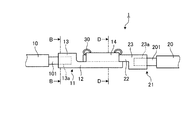
図1は、本実施の形態1にかかるコネクタ1の構成を模式的に示す斜視図である。図2は、本実施の形態1にかかるコネクタ1の構成を模式的に示す側面図である。図1,2に示すコネクタ1は、接続対象物とそれぞれ連結した端子同士が接触することで、2つの接続対象物の間に介在してこの2つの接続対象物間の電気的導通を行なうものである。
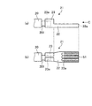
つぎに、本発明の実施の形態2について、図18を参照して説明する。図18は、本実施の形態2にかかるコネクタ2の構成を模式的に示す斜視図である。図18に示すコネクタ2は、接続対象物とそれぞれ連結した端子同士が接触して連結することで接続対象物間の電気的導通を行なうものである。なお、図1等で上述したコネクタと同じ構成要素には同じ符号を付してある。
つぎに、本発明の実施の形態3について、図25を参照して説明する。図25は、本実施の形態3にかかるコネクタ3の構成を模式的に示す斜視図である。図25に示すコネクタ3は、接続対象物とそれぞれ連結した端子同士が接触して連結することで接続対象物間の電気的導通を行なうものである。なお、図1等で上述したコネクタと同じ構成要素には同じ符号を付してある。
10,20 導体
11,11a,11b,21,21a,21b,40,40a,50,50a,60,70 端子
12,15,15b,17,17b,22,24,24b,25,25b,41,42,51,52,61,71 接触部
12a,15a,15c,17a,17c,22a,24a,24c,25a,25c,61a,71a 歯部
13,23,18,26 基部
13a,23a 収容部
14 湾曲部
16 保持部
18a,26a 収容穴
30,31 固定部材
41a,42a 凹部
51a,52a 凸部
101,201 電力線群
120,120a,220,220a 単体歯
121,221 歯先
122,222 歯底
123,223 斜面部
124,224 曲面部
Claims (9)
- 二つの接続対象物の間に介在して該二つの接続対象物間の電気的な導通を図るコネクタであって、
一方の表面が複数の連なる凹凸形状をなす第1歯部を有する板状の第1接触部と、前記第1接触部につながって、一方の接続対象物と接続する第1基部と、を有する導電性の第1端子と、
一方の表面が複数の連なる凹凸形状をなし、前記第1歯部と歯合可能な第2歯部を有する板状の第2接触部と、前記第2接触部につながって、他方の接続対象物と接続する第2基部と、を有する導電性の第2端子と、
を備え、前記第1歯部と前記第2歯部とが歯合することによって前記第1端子および前記第2端子の間が電気的に接続し、
前記第1および第2歯部のピッチ線の形状は、非歯合状態において互いに異なることを特徴とするコネクタ。 - 二つの接続対象物の間に介在して該二つの接続対象物間の電気的な導通を図るコネクタであって、
一方の表面が複数の連なる凹凸形状をなす第1歯部を有する板状の第1接触部と、前記第1接触部につながって、一方の接続対象物と接続する第1基部と、を有する導電性の第1端子と、
一方の表面が複数の連なる凹凸形状をなし、前記第1歯部と歯合可能な第2歯部を有する板状の第2接触部と、前記第2接触部につながって、他方の接続対象物と接続する第2基部と、を有する導電性の第2端子と、
を備え、前記第1歯部と前記第2歯部とが歯合することによって前記第1端子および前記第2端子の間が電気的に接続し、
前記第1および第2歯部のピッチ線の形状は、非歯合状態において同一であることを特徴とするコネクタ。 - 前記第1歯部の歯先につながる側面のなす角度は、前記第2歯部の歯底につながる側面のなす角度と同一であることを特徴とする請求項1または2に記載のコネクタ。
- 前記第1歯部の歯先につながる側面間の最大距離は、前記第2歯部の歯底につながる側面間の最大距離と同一であることを特徴とする請求項1または2に記載のコネクタ。
- 前記第1および第2接触部は、その形状が湾曲し、
前記第1および第2歯部のピッチ線がそれぞれ弧状をなしていることを特徴とする請求項1〜4のいずれか一つに記載のコネクタ。 - 前記第1接触部の幅方向の端部から折り返される方向にそれぞれ延びるとともに、先端側の面が前記第1接触部と対向するように湾曲されてなる湾曲部を有し、
前記第2接触部を前記第1接触部と前記湾曲部とがなす内部空間内に挿入した状態において、前記湾曲部と前記第2接触部とを互いに遠ざける方向に付勢する第1の部材をさらに備えたことを特徴とする請求項1〜5のいずれか一つに記載のコネクタ。 - 前記第1接触部の幅方向の端部から折り返される方向に延びるとともに、先端側の面が前記第1接触部と対向するように湾曲され、前記第1接触部と前記第2接触部とを重ねた状態で、前記第2接触部を覆って保持する保持部を有することを特徴とする請求項1〜5のいずれか一つに記載のコネクタ。
- 前記第1および第2接触部を重ねた状態において、前記第1および第2接触部に巻回されて、前記第1および第2接触部を互いに近づける方向に付勢する第2の部材をさらに備えたことを特徴とする請求項1〜5のいずれか一つに記載のコネクタ。
- 前記第1歯部の単体歯先の半径は、前記第2歯部の単体歯底の半径より大きいことを特徴とする請求項1〜8のいずれか一つに記載のコネクタ。
Applications Claiming Priority (3)
| Application Number | Priority Date | Filing Date | Title |
|---|---|---|---|
| JP2012061168 | 2012-03-16 | ||
| JP2012061168 | 2012-03-16 | ||
| PCT/JP2013/057277 WO2013137415A1 (ja) | 2012-03-16 | 2013-03-14 | コネクタ |
Publications (2)
| Publication Number | Publication Date |
|---|---|
| JPWO2013137415A1 JPWO2013137415A1 (ja) | 2015-08-03 |
| JP6009536B2 true JP6009536B2 (ja) | 2016-10-19 |
Family
ID=49161315
Family Applications (1)
| Application Number | Title | Priority Date | Filing Date |
|---|---|---|---|
| JP2014505010A Expired - Fee Related JP6009536B2 (ja) | 2012-03-16 | 2013-03-14 | コネクタ |
Country Status (4)
| Country | Link |
|---|---|
| US (1) | US9270043B2 (ja) |
| JP (1) | JP6009536B2 (ja) |
| CN (1) | CN104170173A (ja) |
| WO (1) | WO2013137415A1 (ja) |
Families Citing this family (13)
| Publication number | Priority date | Publication date | Assignee | Title |
|---|---|---|---|---|
| JP6301717B2 (ja) * | 2014-04-18 | 2018-03-28 | 矢崎総業株式会社 | 接点接続構造 |
| JP5831611B1 (ja) * | 2014-09-19 | 2015-12-09 | 第一精工株式会社 | コネクタ端子の接続構造 |
| JP1537722S (ja) * | 2015-02-23 | 2015-11-16 | ||
| CN104880589A (zh) * | 2015-06-11 | 2015-09-02 | 江阴长仪集团有限公司 | 一种用于智能电表上分流片与接线端子的连接结构及连接状态检测方法 |
| JP6760142B2 (ja) * | 2017-03-08 | 2020-09-23 | 株式会社オートネットワーク技術研究所 | 雄端子 |
| JP7054432B2 (ja) * | 2017-07-12 | 2022-04-14 | 株式会社オートネットワーク技術研究所 | 雄端子金具及び雌端子金具 |
| JP6939625B2 (ja) | 2018-02-15 | 2021-09-22 | 株式会社オートネットワーク技術研究所 | 端子、及び端子付き電線 |
| US11569604B2 (en) * | 2018-11-16 | 2023-01-31 | Autonetworks Technologies, Ltd. | Connector |
| JP7388221B2 (ja) * | 2020-02-10 | 2023-11-29 | 住友電装株式会社 | 雄端子金具および端子構造 |
| JP7444043B2 (ja) * | 2020-12-16 | 2024-03-06 | 株式会社オートネットワーク技術研究所 | 端子ユニット |
| JP7495671B2 (ja) * | 2021-03-04 | 2024-06-05 | 株式会社オートネットワーク技術研究所 | 端子ユニット,雌端子,雄端子 |
| JP2023161127A (ja) * | 2022-04-25 | 2023-11-07 | 日本航空電子工業株式会社 | 接続構造 |
| JP2024036858A (ja) * | 2022-09-06 | 2024-03-18 | 株式会社オートネットワーク技術研究所 | 端子ユニット,雌端子,雄端子 |
Family Cites Families (21)
| Publication number | Priority date | Publication date | Assignee | Title |
|---|---|---|---|---|
| US2735998A (en) * | 1956-02-21 | Martines | ||
| US2336385A (en) * | 1941-03-14 | 1943-12-07 | Standard Mfg Co | Electric connector |
| JPS5344031Y2 (ja) * | 1972-07-22 | 1978-10-23 | ||
| JPS5862572A (ja) | 1981-10-09 | 1983-04-14 | Canon Inc | マイクロ波検知体 |
| JPS5862572U (ja) * | 1981-10-23 | 1983-04-27 | 古河電気工業株式会社 | 配線分岐箱 |
| US4778231A (en) * | 1984-09-28 | 1988-10-18 | North American Specialties Corp. | Electrical connector |
| JPS62135374U (ja) | 1986-02-19 | 1987-08-26 | ||
| JPH0344869U (ja) * | 1989-09-08 | 1991-04-25 | ||
| JPH0646586B2 (ja) | 1990-11-26 | 1994-06-15 | 矢崎総業株式会社 | 雄端子の製造方法 |
| JP3104420B2 (ja) | 1992-07-10 | 2000-10-30 | 株式会社島津製作所 | 繊維強化複合材料用プリフォームの製造法 |
| JPH0633371U (ja) * | 1992-09-30 | 1994-04-28 | 日本航空電子工業株式会社 | 雄コンタクト |
| US5281178A (en) * | 1992-10-26 | 1994-01-25 | Yazaki Corporation | Electrical connector with feature for increased contact area |
| FR2707806B1 (fr) * | 1993-07-12 | 1995-09-29 | Fels Const Electr | Dispositif de connexion modulaire à grand débattement. |
| US6068526A (en) * | 1996-06-17 | 2000-05-30 | Framatome Connectors International | Connector bushing having an improved central base zone |
| JPH11307159A (ja) * | 1998-04-16 | 1999-11-05 | Kansei Corp | 電気接続端子 |
| JP2001110479A (ja) * | 1999-10-12 | 2001-04-20 | Sumitomo Wiring Syst Ltd | 端子金具 |
| US20030060090A1 (en) * | 2001-09-21 | 2003-03-27 | Allgood Christopher L. | High current automotive electrical connector and terminal |
| JP2003142213A (ja) | 2001-11-06 | 2003-05-16 | D D K Ltd | 電気コネクタ |
| JP2005332658A (ja) | 2004-05-19 | 2005-12-02 | Fujikura Ltd | コネクタ |
| JP4613820B2 (ja) | 2005-12-28 | 2011-01-19 | 日立電線株式会社 | 端子接続構造 |
| CN201126879Y (zh) | 2007-11-26 | 2008-10-01 | 华为技术有限公司 | 一种电连接端子 |
-
2013
- 2013-03-14 JP JP2014505010A patent/JP6009536B2/ja not_active Expired - Fee Related
- 2013-03-14 US US14/385,209 patent/US9270043B2/en not_active Expired - Fee Related
- 2013-03-14 CN CN201380014340.3A patent/CN104170173A/zh active Pending
- 2013-03-14 WO PCT/JP2013/057277 patent/WO2013137415A1/ja not_active Ceased
Also Published As
| Publication number | Publication date |
|---|---|
| CN104170173A (zh) | 2014-11-26 |
| US20150056875A1 (en) | 2015-02-26 |
| WO2013137415A1 (ja) | 2013-09-19 |
| US9270043B2 (en) | 2016-02-23 |
| JPWO2013137415A1 (ja) | 2015-08-03 |
Similar Documents
| Publication | Publication Date | Title |
|---|---|---|
| JP6009536B2 (ja) | コネクタ | |
| US9190750B2 (en) | Board-to-board connector | |
| JP6293431B2 (ja) | 電気コネクタ | |
| TWI351792B (en) | Connector | |
| US8888520B2 (en) | Contact with pair of pins each with a folded end | |
| JP5286190B2 (ja) | 同軸コネクタ、及びコネクタ装置 | |
| JP6126082B2 (ja) | コネクタ | |
| JP6006356B2 (ja) | コンタクト及び該コンタクトを使用するコネクタ | |
| JP2013055007A (ja) | コネクタ | |
| WO2017104388A1 (ja) | 端子金具及びコネクタ | |
| US8668499B2 (en) | Connector | |
| US20140038476A1 (en) | Connector | |
| JP4021397B2 (ja) | 接続端子及び該接続端子を用いるジョイントコネクタ | |
| CN104756322A (zh) | 阳端子 | |
| JP5897978B2 (ja) | 突き当て型の端子金具 | |
| US8979552B2 (en) | Connector and method for connecting the connector | |
| CN110226263A (zh) | 端子模块 | |
| JP2011181420A (ja) | ブレードおよびこれを用いたコネクタセット | |
| JP2007059304A (ja) | 端子付き電線とその製造方法 | |
| JP2017117623A (ja) | コネクタ | |
| CN102959810B (zh) | 被屏蔽的插塞连接器 | |
| WO2013183301A1 (en) | Terminal connection structure | |
| JP6253755B2 (ja) | 導体接続構造 | |
| JP6606925B2 (ja) | 電気コネクタ | |
| JP2013093273A (ja) | フレキシブル基板における端子接合構造 |
Legal Events
| Date | Code | Title | Description |
|---|---|---|---|
| A621 | Written request for application examination |
Free format text: JAPANESE INTERMEDIATE CODE: A621 Effective date: 20150803 |
|
| A131 | Notification of reasons for refusal |
Free format text: JAPANESE INTERMEDIATE CODE: A131 Effective date: 20160524 |
|
| A521 | Request for written amendment filed |
Free format text: JAPANESE INTERMEDIATE CODE: A523 Effective date: 20160725 |
|
| TRDD | Decision of grant or rejection written | ||
| A01 | Written decision to grant a patent or to grant a registration (utility model) |
Free format text: JAPANESE INTERMEDIATE CODE: A01 Effective date: 20160906 |
|
| A61 | First payment of annual fees (during grant procedure) |
Free format text: JAPANESE INTERMEDIATE CODE: A61 Effective date: 20160914 |
|
| R150 | Certificate of patent or registration of utility model |
Ref document number: 6009536 Country of ref document: JP Free format text: JAPANESE INTERMEDIATE CODE: R150 |
|
| R250 | Receipt of annual fees |
Free format text: JAPANESE INTERMEDIATE CODE: R250 |
|
| LAPS | Cancellation because of no payment of annual fees |