WO2011108269A1 - 炭素繊維の製造方法 - Google Patents
炭素繊維の製造方法 Download PDFInfo
- Publication number
- WO2011108269A1 WO2011108269A1 PCT/JP2011/001233 JP2011001233W WO2011108269A1 WO 2011108269 A1 WO2011108269 A1 WO 2011108269A1 JP 2011001233 W JP2011001233 W JP 2011001233W WO 2011108269 A1 WO2011108269 A1 WO 2011108269A1
- Authority
- WO
- WIPO (PCT)
- Prior art keywords
- catalyst
- intensity
- colloid
- carrier
- powdery carrier
- Prior art date
Links
- 229920000049 Carbon (fiber) Polymers 0.000 title claims abstract description 111
- 239000004917 carbon fiber Substances 0.000 title claims abstract description 111
- 238000000034 method Methods 0.000 title claims abstract description 61
- 238000004519 manufacturing process Methods 0.000 title claims description 50
- 230000008569 process Effects 0.000 title abstract description 5
- 239000003054 catalyst Substances 0.000 claims abstract description 178
- 239000000084 colloidal system Substances 0.000 claims abstract description 59
- 239000002245 particle Substances 0.000 claims abstract description 46
- 229910052799 carbon Inorganic materials 0.000 claims abstract description 37
- 150000001875 compounds Chemical class 0.000 claims abstract description 37
- 150000001721 carbon Chemical group 0.000 claims abstract description 31
- 238000002441 X-ray diffraction Methods 0.000 claims abstract description 17
- 239000013078 crystal Substances 0.000 claims abstract description 13
- 125000004432 carbon atom Chemical group C* 0.000 claims abstract description 9
- VNWKTOKETHGBQD-UHFFFAOYSA-N methane Chemical compound C VNWKTOKETHGBQD-UHFFFAOYSA-N 0.000 claims description 89
- CPLXHLVBOLITMK-UHFFFAOYSA-N magnesium oxide Inorganic materials [Mg]=O CPLXHLVBOLITMK-UHFFFAOYSA-N 0.000 claims description 53
- 239000000835 fiber Substances 0.000 claims description 43
- 239000000843 powder Substances 0.000 claims description 36
- 239000007788 liquid Substances 0.000 claims description 30
- 239000004094 surface-active agent Substances 0.000 claims description 25
- 239000000395 magnesium oxide Substances 0.000 claims description 24
- 238000010438 heat treatment Methods 0.000 claims description 19
- 238000006243 chemical reaction Methods 0.000 claims description 15
- 229910052751 metal Inorganic materials 0.000 claims description 15
- 239000002184 metal Substances 0.000 claims description 14
- 239000000203 mixture Substances 0.000 claims description 10
- 229910001507 metal halide Inorganic materials 0.000 claims description 7
- 150000005309 metal halides Chemical class 0.000 claims description 7
- 238000002156 mixing Methods 0.000 claims description 6
- 238000001035 drying Methods 0.000 claims description 5
- 238000011068 loading method Methods 0.000 claims description 5
- 239000011777 magnesium Substances 0.000 claims description 3
- 238000005470 impregnation Methods 0.000 claims description 2
- AXZKOIWUVFPNLO-UHFFFAOYSA-N magnesium;oxygen(2-) Chemical compound [O-2].[Mg+2] AXZKOIWUVFPNLO-UHFFFAOYSA-N 0.000 claims 2
- 229940126062 Compound A Drugs 0.000 claims 1
- NLDMNSXOCDLTTB-UHFFFAOYSA-N Heterophylliin A Natural products O1C2COC(=O)C3=CC(O)=C(O)C(O)=C3C3=C(O)C(O)=C(O)C=C3C(=O)OC2C(OC(=O)C=2C=C(O)C(O)=C(O)C=2)C(O)C1OC(=O)C1=CC(O)=C(O)C(O)=C1 NLDMNSXOCDLTTB-UHFFFAOYSA-N 0.000 claims 1
- 230000003197 catalytic effect Effects 0.000 claims 1
- 229920005989 resin Polymers 0.000 abstract description 22
- 239000011347 resin Substances 0.000 abstract description 22
- 239000002131 composite material Substances 0.000 abstract description 12
- VLKZOEOYAKHREP-UHFFFAOYSA-N n-Hexane Chemical compound CCCCCC VLKZOEOYAKHREP-UHFFFAOYSA-N 0.000 description 27
- OKTJSMMVPCPJKN-UHFFFAOYSA-N Carbon Chemical compound [C] OKTJSMMVPCPJKN-UHFFFAOYSA-N 0.000 description 24
- 230000000052 comparative effect Effects 0.000 description 19
- 239000007789 gas Substances 0.000 description 16
- -1 that is Chemical compound 0.000 description 16
- LFQSCWFLJHTTHZ-UHFFFAOYSA-N Ethanol Chemical compound CCO LFQSCWFLJHTTHZ-UHFFFAOYSA-N 0.000 description 15
- YXFVVABEGXRONW-UHFFFAOYSA-N Toluene Chemical compound CC1=CC=CC=C1 YXFVVABEGXRONW-UHFFFAOYSA-N 0.000 description 15
- XEEYBQQBJWHFJM-UHFFFAOYSA-N iron Substances [Fe] XEEYBQQBJWHFJM-UHFFFAOYSA-N 0.000 description 15
- IJGRMHOSHXDMSA-UHFFFAOYSA-N Atomic nitrogen Chemical compound N#N IJGRMHOSHXDMSA-UHFFFAOYSA-N 0.000 description 13
- UHOVQNZJYSORNB-UHFFFAOYSA-N Benzene Chemical compound C1=CC=CC=C1 UHOVQNZJYSORNB-UHFFFAOYSA-N 0.000 description 12
- 239000002041 carbon nanotube Substances 0.000 description 12
- 229910021393 carbon nanotube Inorganic materials 0.000 description 12
- 239000000126 substance Substances 0.000 description 12
- 230000000694 effects Effects 0.000 description 11
- 238000002360 preparation method Methods 0.000 description 11
- 239000000243 solution Substances 0.000 description 10
- RTZKZFJDLAIYFH-UHFFFAOYSA-N Diethyl ether Chemical compound CCOCC RTZKZFJDLAIYFH-UHFFFAOYSA-N 0.000 description 9
- OKKJLVBELUTLKV-UHFFFAOYSA-N Methanol Chemical compound OC OKKJLVBELUTLKV-UHFFFAOYSA-N 0.000 description 9
- 239000011159 matrix material Substances 0.000 description 9
- 239000000758 substrate Substances 0.000 description 9
- OFBQJSOFQDEBGM-UHFFFAOYSA-N Pentane Chemical compound CCCCC OFBQJSOFQDEBGM-UHFFFAOYSA-N 0.000 description 8
- 239000001257 hydrogen Substances 0.000 description 8
- 229910052739 hydrogen Inorganic materials 0.000 description 8
- 239000000463 material Substances 0.000 description 8
- 239000007787 solid Substances 0.000 description 8
- UFHFLCQGNIYNRP-UHFFFAOYSA-N Hydrogen Chemical compound [H][H] UFHFLCQGNIYNRP-UHFFFAOYSA-N 0.000 description 7
- VYPSYNLAJGMNEJ-UHFFFAOYSA-N Silicium dioxide Chemical compound O=[Si]=O VYPSYNLAJGMNEJ-UHFFFAOYSA-N 0.000 description 7
- 239000012159 carrier gas Substances 0.000 description 7
- YMWUJEATGCHHMB-UHFFFAOYSA-N Dichloromethane Chemical compound ClCCl YMWUJEATGCHHMB-UHFFFAOYSA-N 0.000 description 6
- XEKOWRVHYACXOJ-UHFFFAOYSA-N Ethyl acetate Chemical compound CCOC(C)=O XEKOWRVHYACXOJ-UHFFFAOYSA-N 0.000 description 6
- 229910002091 carbon monoxide Inorganic materials 0.000 description 6
- 235000014113 dietary fatty acids Nutrition 0.000 description 6
- 239000000194 fatty acid Substances 0.000 description 6
- 229930195729 fatty acid Natural products 0.000 description 6
- 238000000746 purification Methods 0.000 description 6
- 229910052783 alkali metal Inorganic materials 0.000 description 5
- PNEYBMLMFCGWSK-UHFFFAOYSA-N aluminium oxide Inorganic materials [O-2].[O-2].[O-2].[Al+3].[Al+3] PNEYBMLMFCGWSK-UHFFFAOYSA-N 0.000 description 5
- 238000009835 boiling Methods 0.000 description 5
- 239000000945 filler Substances 0.000 description 5
- 229910021389 graphene Inorganic materials 0.000 description 5
- 238000000465 moulding Methods 0.000 description 5
- 229910052757 nitrogen Inorganic materials 0.000 description 5
- CURLTUGMZLYLDI-UHFFFAOYSA-N Carbon dioxide Chemical compound O=C=O CURLTUGMZLYLDI-UHFFFAOYSA-N 0.000 description 4
- HEDRZPFGACZZDS-UHFFFAOYSA-N Chloroform Chemical compound ClC(Cl)Cl HEDRZPFGACZZDS-UHFFFAOYSA-N 0.000 description 4
- LRHPLDYGYMQRHN-UHFFFAOYSA-N N-Butanol Chemical compound CCCCO LRHPLDYGYMQRHN-UHFFFAOYSA-N 0.000 description 4
- ATUOYWHBWRKTHZ-UHFFFAOYSA-N Propane Chemical compound CCC ATUOYWHBWRKTHZ-UHFFFAOYSA-N 0.000 description 4
- NINIDFKCEFEMDL-UHFFFAOYSA-N Sulfur Chemical compound [S] NINIDFKCEFEMDL-UHFFFAOYSA-N 0.000 description 4
- QVGXLLKOCUKJST-UHFFFAOYSA-N atomic oxygen Chemical compound [O] QVGXLLKOCUKJST-UHFFFAOYSA-N 0.000 description 4
- 230000005540 biological transmission Effects 0.000 description 4
- 239000003153 chemical reaction reagent Substances 0.000 description 4
- 239000000805 composite resin Substances 0.000 description 4
- 239000010419 fine particle Substances 0.000 description 4
- 239000001301 oxygen Substances 0.000 description 4
- 229910052760 oxygen Inorganic materials 0.000 description 4
- 238000000634 powder X-ray diffraction Methods 0.000 description 4
- 150000003839 salts Chemical class 0.000 description 4
- 238000001878 scanning electron micrograph Methods 0.000 description 4
- 229910052717 sulfur Inorganic materials 0.000 description 4
- 239000011593 sulfur Substances 0.000 description 4
- ODINCKMPIJJUCX-UHFFFAOYSA-N Calcium oxide Chemical compound [Ca]=O ODINCKMPIJJUCX-UHFFFAOYSA-N 0.000 description 3
- RGSFGYAAUTVSQA-UHFFFAOYSA-N Cyclopentane Chemical compound C1CCCC1 RGSFGYAAUTVSQA-UHFFFAOYSA-N 0.000 description 3
- VGGSQFUCUMXWEO-UHFFFAOYSA-N Ethene Chemical compound C=C VGGSQFUCUMXWEO-UHFFFAOYSA-N 0.000 description 3
- 239000005977 Ethylene Substances 0.000 description 3
- PXHVJJICTQNCMI-UHFFFAOYSA-N Nickel Chemical compound [Ni] PXHVJJICTQNCMI-UHFFFAOYSA-N 0.000 description 3
- BCKXLBQYZLBQEK-KVVVOXFISA-M Sodium oleate Chemical compound [Na+].CCCCCCCC\C=C/CCCCCCCC([O-])=O BCKXLBQYZLBQEK-KVVVOXFISA-M 0.000 description 3
- 230000002776 aggregation Effects 0.000 description 3
- 239000003945 anionic surfactant Substances 0.000 description 3
- 239000000292 calcium oxide Substances 0.000 description 3
- 235000012255 calcium oxide Nutrition 0.000 description 3
- 239000012018 catalyst precursor Substances 0.000 description 3
- 239000013626 chemical specie Substances 0.000 description 3
- 238000005229 chemical vapour deposition Methods 0.000 description 3
- 239000000460 chlorine Substances 0.000 description 3
- 229910001873 dinitrogen Inorganic materials 0.000 description 3
- 239000003960 organic solvent Substances 0.000 description 3
- 239000002798 polar solvent Substances 0.000 description 3
- 238000001556 precipitation Methods 0.000 description 3
- 239000010453 quartz Substances 0.000 description 3
- 230000009467 reduction Effects 0.000 description 3
- 239000002904 solvent Substances 0.000 description 3
- 239000006228 supernatant Substances 0.000 description 3
- 229920005992 thermoplastic resin Polymers 0.000 description 3
- 229920001187 thermosetting polymer Polymers 0.000 description 3
- FCEHBMOGCRZNNI-UHFFFAOYSA-N 1-benzothiophene Chemical compound C1=CC=C2SC=CC2=C1 FCEHBMOGCRZNNI-UHFFFAOYSA-N 0.000 description 2
- YBYIRNPNPLQARY-UHFFFAOYSA-N 1H-indene Chemical compound C1=CC=C2CC=CC2=C1 YBYIRNPNPLQARY-UHFFFAOYSA-N 0.000 description 2
- XKRFYHLGVUSROY-UHFFFAOYSA-N Argon Chemical compound [Ar] XKRFYHLGVUSROY-UHFFFAOYSA-N 0.000 description 2
- KAKZBPTYRLMSJV-UHFFFAOYSA-N Butadiene Chemical compound C=CC=C KAKZBPTYRLMSJV-UHFFFAOYSA-N 0.000 description 2
- LCGLNKUTAGEVQW-UHFFFAOYSA-N Dimethyl ether Chemical compound COC LCGLNKUTAGEVQW-UHFFFAOYSA-N 0.000 description 2
- OTMSDBZUPAUEDD-UHFFFAOYSA-N Ethane Chemical compound CC OTMSDBZUPAUEDD-UHFFFAOYSA-N 0.000 description 2
- 229910001111 Fine metal Inorganic materials 0.000 description 2
- IMNFDUFMRHMDMM-UHFFFAOYSA-N N-Heptane Chemical compound CCCCCCC IMNFDUFMRHMDMM-UHFFFAOYSA-N 0.000 description 2
- UFWIBTONFRDIAS-UHFFFAOYSA-N Naphthalene Chemical compound C1=CC=CC2=CC=CC=C21 UFWIBTONFRDIAS-UHFFFAOYSA-N 0.000 description 2
- CTQNGGLPUBDAKN-UHFFFAOYSA-N O-Xylene Chemical compound CC1=CC=CC=C1C CTQNGGLPUBDAKN-UHFFFAOYSA-N 0.000 description 2
- KDLHZDBZIXYQEI-UHFFFAOYSA-N Palladium Chemical compound [Pd] KDLHZDBZIXYQEI-UHFFFAOYSA-N 0.000 description 2
- OAICVXFJPJFONN-UHFFFAOYSA-N Phosphorus Chemical compound [P] OAICVXFJPJFONN-UHFFFAOYSA-N 0.000 description 2
- JUJWROOIHBZHMG-UHFFFAOYSA-N Pyridine Chemical compound C1=CC=NC=C1 JUJWROOIHBZHMG-UHFFFAOYSA-N 0.000 description 2
- SMWDFEZZVXVKRB-UHFFFAOYSA-N Quinoline Chemical compound N1=CC=CC2=CC=CC=C21 SMWDFEZZVXVKRB-UHFFFAOYSA-N 0.000 description 2
- PPBRXRYQALVLMV-UHFFFAOYSA-N Styrene Chemical compound C=CC1=CC=CC=C1 PPBRXRYQALVLMV-UHFFFAOYSA-N 0.000 description 2
- YTPLMLYBLZKORZ-UHFFFAOYSA-N Thiophene Chemical compound C=1C=CSC=1 YTPLMLYBLZKORZ-UHFFFAOYSA-N 0.000 description 2
- MCMNRKCIXSYSNV-UHFFFAOYSA-N Zirconium dioxide Chemical compound O=[Zr]=O MCMNRKCIXSYSNV-UHFFFAOYSA-N 0.000 description 2
- 238000010521 absorption reaction Methods 0.000 description 2
- 238000004220 aggregation Methods 0.000 description 2
- 125000000217 alkyl group Chemical group 0.000 description 2
- HSFWRNGVRCDJHI-UHFFFAOYSA-N alpha-acetylene Natural products C#C HSFWRNGVRCDJHI-UHFFFAOYSA-N 0.000 description 2
- MWPLVEDNUUSJAV-UHFFFAOYSA-N anthracene Chemical compound C1=CC=CC2=CC3=CC=CC=C3C=C21 MWPLVEDNUUSJAV-UHFFFAOYSA-N 0.000 description 2
- 230000015572 biosynthetic process Effects 0.000 description 2
- 239000001273 butane Substances 0.000 description 2
- 239000001569 carbon dioxide Substances 0.000 description 2
- 229910002092 carbon dioxide Inorganic materials 0.000 description 2
- 239000003093 cationic surfactant Substances 0.000 description 2
- 238000005119 centrifugation Methods 0.000 description 2
- 229910052801 chlorine Inorganic materials 0.000 description 2
- 229910052804 chromium Inorganic materials 0.000 description 2
- 239000011651 chromium Substances 0.000 description 2
- HGCIXCUEYOPUTN-UHFFFAOYSA-N cyclohexene Chemical compound C1CCC=CC1 HGCIXCUEYOPUTN-UHFFFAOYSA-N 0.000 description 2
- ZSWFCLXCOIISFI-UHFFFAOYSA-N cyclopentadiene Chemical compound C1C=CC=C1 ZSWFCLXCOIISFI-UHFFFAOYSA-N 0.000 description 2
- LPIQUOYDBNQMRZ-UHFFFAOYSA-N cyclopentene Chemical compound C1CC=CC1 LPIQUOYDBNQMRZ-UHFFFAOYSA-N 0.000 description 2
- 238000001739 density measurement Methods 0.000 description 2
- 239000006185 dispersion Substances 0.000 description 2
- POULHZVOKOAJMA-UHFFFAOYSA-N dodecanoic acid Chemical compound CCCCCCCCCCCC(O)=O POULHZVOKOAJMA-UHFFFAOYSA-N 0.000 description 2
- 239000007772 electrode material Substances 0.000 description 2
- 125000002534 ethynyl group Chemical group [H]C#C* 0.000 description 2
- 150000004665 fatty acids Chemical class 0.000 description 2
- 238000010574 gas phase reaction Methods 0.000 description 2
- 239000011521 glass Substances 0.000 description 2
- 230000005484 gravity Effects 0.000 description 2
- 150000004820 halides Chemical class 0.000 description 2
- IPCSVZSSVZVIGE-UHFFFAOYSA-N hexadecanoic acid Chemical compound CCCCCCCCCCCCCCCC(O)=O IPCSVZSSVZVIGE-UHFFFAOYSA-N 0.000 description 2
- 229930195733 hydrocarbon Natural products 0.000 description 2
- 150000002430 hydrocarbons Chemical class 0.000 description 2
- 230000001771 impaired effect Effects 0.000 description 2
- 239000012535 impurity Substances 0.000 description 2
- 229910052742 iron Inorganic materials 0.000 description 2
- NMCUIPGRVMDVDB-UHFFFAOYSA-L iron dichloride Chemical compound Cl[Fe]Cl NMCUIPGRVMDVDB-UHFFFAOYSA-L 0.000 description 2
- NQXWGWZJXJUMQB-UHFFFAOYSA-K iron trichloride hexahydrate Chemical compound O.O.O.O.O.O.[Cl-].Cl[Fe+]Cl NQXWGWZJXJUMQB-UHFFFAOYSA-K 0.000 description 2
- 239000003350 kerosene Substances 0.000 description 2
- 238000004898 kneading Methods 0.000 description 2
- 238000002844 melting Methods 0.000 description 2
- 230000008018 melting Effects 0.000 description 2
- 229910052750 molybdenum Inorganic materials 0.000 description 2
- IJDNQMDRQITEOD-UHFFFAOYSA-N n-butane Chemical compound CCCC IJDNQMDRQITEOD-UHFFFAOYSA-N 0.000 description 2
- 229910052759 nickel Inorganic materials 0.000 description 2
- 239000002736 nonionic surfactant Substances 0.000 description 2
- WWZKQHOCKIZLMA-UHFFFAOYSA-N octanoic acid Chemical compound CCCCCCCC(O)=O WWZKQHOCKIZLMA-UHFFFAOYSA-N 0.000 description 2
- 239000003921 oil Substances 0.000 description 2
- 238000004806 packaging method and process Methods 0.000 description 2
- YNPNZTXNASCQKK-UHFFFAOYSA-N phenanthrene Chemical compound C1=CC=C2C3=CC=CC=C3C=CC2=C1 YNPNZTXNASCQKK-UHFFFAOYSA-N 0.000 description 2
- 239000011574 phosphorus Substances 0.000 description 2
- 229910052698 phosphorus Inorganic materials 0.000 description 2
- BASFCYQUMIYNBI-UHFFFAOYSA-N platinum Chemical compound [Pt] BASFCYQUMIYNBI-UHFFFAOYSA-N 0.000 description 2
- 239000000047 product Substances 0.000 description 2
- BDERNNFJNOPAEC-UHFFFAOYSA-N propan-1-ol Chemical compound CCCO BDERNNFJNOPAEC-UHFFFAOYSA-N 0.000 description 2
- 239000001294 propane Substances 0.000 description 2
- 239000000377 silicon dioxide Substances 0.000 description 2
- 238000003786 synthesis reaction Methods 0.000 description 2
- RMVRSNDYEFQCLF-UHFFFAOYSA-N thiophenol Chemical compound SC1=CC=CC=C1 RMVRSNDYEFQCLF-UHFFFAOYSA-N 0.000 description 2
- 239000010936 titanium Substances 0.000 description 2
- 229910052719 titanium Inorganic materials 0.000 description 2
- 229910052721 tungsten Inorganic materials 0.000 description 2
- 229910052720 vanadium Inorganic materials 0.000 description 2
- XLYOFNOQVPJJNP-UHFFFAOYSA-N water Substances O XLYOFNOQVPJJNP-UHFFFAOYSA-N 0.000 description 2
- 239000008096 xylene Substances 0.000 description 2
- KAKVFSYQVNHFBS-UHFFFAOYSA-N (5-hydroxycyclopenten-1-yl)-phenylmethanone Chemical compound OC1CCC=C1C(=O)C1=CC=CC=C1 KAKVFSYQVNHFBS-UHFFFAOYSA-N 0.000 description 1
- WRIDQFICGBMAFQ-UHFFFAOYSA-N (E)-8-Octadecenoic acid Natural products CCCCCCCCCC=CCCCCCCC(O)=O WRIDQFICGBMAFQ-UHFFFAOYSA-N 0.000 description 1
- SOQQSPURSLWWMI-UHFFFAOYSA-N 1,3-thiazole-4-carbothioamide Chemical compound NC(=S)C1=CSC=N1 SOQQSPURSLWWMI-UHFFFAOYSA-N 0.000 description 1
- HECLRDQVFMWTQS-RGOKHQFPSA-N 1755-01-7 Chemical compound C1[C@H]2[C@@H]3CC=C[C@@H]3[C@@H]1C=C2 HECLRDQVFMWTQS-RGOKHQFPSA-N 0.000 description 1
- WHRZCXAVMTUTDD-UHFFFAOYSA-N 1h-furo[2,3-d]pyrimidin-2-one Chemical compound N1C(=O)N=C2OC=CC2=C1 WHRZCXAVMTUTDD-UHFFFAOYSA-N 0.000 description 1
- LQJBNNIYVWPHFW-UHFFFAOYSA-N 20:1omega9c fatty acid Natural products CCCCCCCCCCC=CCCCCCCCC(O)=O LQJBNNIYVWPHFW-UHFFFAOYSA-N 0.000 description 1
- ZCYVEMRRCGMTRW-UHFFFAOYSA-N 7553-56-2 Chemical compound [I] ZCYVEMRRCGMTRW-UHFFFAOYSA-N 0.000 description 1
- QSBYPNXLFMSGKH-UHFFFAOYSA-N 9-Heptadecensaeure Natural products CCCCCCCC=CCCCCCCCC(O)=O QSBYPNXLFMSGKH-UHFFFAOYSA-N 0.000 description 1
- 238000004438 BET method Methods 0.000 description 1
- WKBOTKDWSSQWDR-UHFFFAOYSA-N Bromine atom Chemical compound [Br] WKBOTKDWSSQWDR-UHFFFAOYSA-N 0.000 description 1
- 239000005635 Caprylic acid (CAS 124-07-2) Substances 0.000 description 1
- 239000004215 Carbon black (E152) Substances 0.000 description 1
- ZAMOUSCENKQFHK-UHFFFAOYSA-N Chlorine atom Chemical compound [Cl] ZAMOUSCENKQFHK-UHFFFAOYSA-N 0.000 description 1
- VYZAMTAEIAYCRO-UHFFFAOYSA-N Chromium Chemical compound [Cr] VYZAMTAEIAYCRO-UHFFFAOYSA-N 0.000 description 1
- 229920000089 Cyclic olefin copolymer Polymers 0.000 description 1
- XDTMQSROBMDMFD-UHFFFAOYSA-N Cyclohexane Chemical compound C1CCCCC1 XDTMQSROBMDMFD-UHFFFAOYSA-N 0.000 description 1
- LVZWSLJZHVFIQJ-UHFFFAOYSA-N Cyclopropane Chemical compound C1CC1 LVZWSLJZHVFIQJ-UHFFFAOYSA-N 0.000 description 1
- 239000001293 FEMA 3089 Substances 0.000 description 1
- PXGOKWXKJXAPGV-UHFFFAOYSA-N Fluorine Chemical compound FF PXGOKWXKJXAPGV-UHFFFAOYSA-N 0.000 description 1
- 235000006173 Larrea tridentata Nutrition 0.000 description 1
- 244000073231 Larrea tridentata Species 0.000 description 1
- 239000005639 Lauric acid Substances 0.000 description 1
- OYHQOLUKZRVURQ-HZJYTTRNSA-N Linoleic acid Chemical compound CCCCC\C=C/C\C=C/CCCCCCCC(O)=O OYHQOLUKZRVURQ-HZJYTTRNSA-N 0.000 description 1
- 239000012448 Lithium borohydride Substances 0.000 description 1
- LSDPWZHWYPCBBB-UHFFFAOYSA-N Methanethiol Chemical compound SC LSDPWZHWYPCBBB-UHFFFAOYSA-N 0.000 description 1
- ZOKXTWBITQBERF-UHFFFAOYSA-N Molybdenum Chemical compound [Mo] ZOKXTWBITQBERF-UHFFFAOYSA-N 0.000 description 1
- 239000004677 Nylon Substances 0.000 description 1
- 239000005642 Oleic acid Substances 0.000 description 1
- ZQPPMHVWECSIRJ-UHFFFAOYSA-N Oleic acid Natural products CCCCCCCCC=CCCCCCCCC(O)=O ZQPPMHVWECSIRJ-UHFFFAOYSA-N 0.000 description 1
- 229910019142 PO4 Inorganic materials 0.000 description 1
- 235000021314 Palmitic acid Nutrition 0.000 description 1
- 239000004952 Polyamide Substances 0.000 description 1
- 239000002202 Polyethylene glycol Substances 0.000 description 1
- 239000004642 Polyimide Substances 0.000 description 1
- 239000004721 Polyphenylene oxide Substances 0.000 description 1
- ZLMJMSJWJFRBEC-UHFFFAOYSA-N Potassium Chemical compound [K] ZLMJMSJWJFRBEC-UHFFFAOYSA-N 0.000 description 1
- KJTLSVCANCCWHF-UHFFFAOYSA-N Ruthenium Chemical compound [Ru] KJTLSVCANCCWHF-UHFFFAOYSA-N 0.000 description 1
- 235000021355 Stearic acid Nutrition 0.000 description 1
- 238000003917 TEM image Methods 0.000 description 1
- RTAQQCXQSZGOHL-UHFFFAOYSA-N Titanium Chemical compound [Ti] RTAQQCXQSZGOHL-UHFFFAOYSA-N 0.000 description 1
- XSTXAVWGXDQKEL-UHFFFAOYSA-N Trichloroethylene Chemical group ClC=C(Cl)Cl XSTXAVWGXDQKEL-UHFFFAOYSA-N 0.000 description 1
- 229910021536 Zeolite Inorganic materials 0.000 description 1
- PFRUBEOIWWEFOL-UHFFFAOYSA-N [N].[S] Chemical compound [N].[S] PFRUBEOIWWEFOL-UHFFFAOYSA-N 0.000 description 1
- 150000001242 acetic acid derivatives Chemical class 0.000 description 1
- YRKCREAYFQTBPV-UHFFFAOYSA-N acetylacetone Chemical class CC(=O)CC(C)=O YRKCREAYFQTBPV-UHFFFAOYSA-N 0.000 description 1
- 239000002253 acid Substances 0.000 description 1
- 238000005054 agglomeration Methods 0.000 description 1
- 150000001335 aliphatic alkanes Chemical class 0.000 description 1
- 150000007824 aliphatic compounds Chemical class 0.000 description 1
- 150000001338 aliphatic hydrocarbons Chemical class 0.000 description 1
- 150000001336 alkenes Chemical class 0.000 description 1
- 150000001345 alkine derivatives Chemical class 0.000 description 1
- 239000002216 antistatic agent Substances 0.000 description 1
- 229910052786 argon Inorganic materials 0.000 description 1
- 150000001491 aromatic compounds Chemical class 0.000 description 1
- 150000004945 aromatic hydrocarbons Chemical class 0.000 description 1
- GDTBXPJZTBHREO-UHFFFAOYSA-N bromine Substances BrBr GDTBXPJZTBHREO-UHFFFAOYSA-N 0.000 description 1
- 229910052794 bromium Inorganic materials 0.000 description 1
- 239000010624 camphor oil Substances 0.000 description 1
- 229960000411 camphor oil Drugs 0.000 description 1
- 239000006229 carbon black Substances 0.000 description 1
- 125000002915 carbonyl group Chemical group [*:2]C([*:1])=O 0.000 description 1
- 150000007942 carboxylates Chemical class 0.000 description 1
- 239000000969 carrier Substances 0.000 description 1
- 239000003638 chemical reducing agent Substances 0.000 description 1
- HRYZWHHZPQKTII-UHFFFAOYSA-N chloroethane Chemical compound CCCl HRYZWHHZPQKTII-UHFFFAOYSA-N 0.000 description 1
- 229910017052 cobalt Inorganic materials 0.000 description 1
- 239000010941 cobalt Substances 0.000 description 1
- GUTLYIVDDKVIGB-UHFFFAOYSA-N cobalt atom Chemical compound [Co] GUTLYIVDDKVIGB-UHFFFAOYSA-N 0.000 description 1
- 238000000366 colloid method Methods 0.000 description 1
- 239000011231 conductive filler Substances 0.000 description 1
- 238000001816 cooling Methods 0.000 description 1
- 150000004696 coordination complex Chemical class 0.000 description 1
- PMHQVHHXPFUNSP-UHFFFAOYSA-M copper(1+);methylsulfanylmethane;bromide Chemical compound Br[Cu].CSC PMHQVHHXPFUNSP-UHFFFAOYSA-M 0.000 description 1
- 229960002126 creosote Drugs 0.000 description 1
- 150000001925 cycloalkenes Chemical class 0.000 description 1
- 239000010727 cylinder oil Substances 0.000 description 1
- 238000010908 decantation Methods 0.000 description 1
- 230000007547 defect Effects 0.000 description 1
- 230000003111 delayed effect Effects 0.000 description 1
- 230000006866 deterioration Effects 0.000 description 1
- XYWDPYKBIRQXQS-UHFFFAOYSA-N di-isopropyl sulphide Natural products CC(C)SC(C)C XYWDPYKBIRQXQS-UHFFFAOYSA-N 0.000 description 1
- HNPSIPDUKPIQMN-UHFFFAOYSA-N dioxosilane;oxo(oxoalumanyloxy)alumane Chemical compound O=[Si]=O.O=[Al]O[Al]=O HNPSIPDUKPIQMN-UHFFFAOYSA-N 0.000 description 1
- LTYMSROWYAPPGB-UHFFFAOYSA-N diphenyl sulfide Chemical compound C=1C=CC=CC=1SC1=CC=CC=C1 LTYMSROWYAPPGB-UHFFFAOYSA-N 0.000 description 1
- 239000012153 distilled water Substances 0.000 description 1
- 238000009826 distribution Methods 0.000 description 1
- 239000002079 double walled nanotube Substances 0.000 description 1
- 238000009503 electrostatic coating Methods 0.000 description 1
- 239000003822 epoxy resin Substances 0.000 description 1
- 150000002148 esters Chemical class 0.000 description 1
- 229960003750 ethyl chloride Drugs 0.000 description 1
- 238000001125 extrusion Methods 0.000 description 1
- 239000011737 fluorine Substances 0.000 description 1
- 229910052731 fluorine Inorganic materials 0.000 description 1
- 235000021588 free fatty acids Nutrition 0.000 description 1
- 239000000295 fuel oil Substances 0.000 description 1
- 239000003502 gasoline Substances 0.000 description 1
- 239000012208 gear oil Substances 0.000 description 1
- 229910002804 graphite Inorganic materials 0.000 description 1
- 239000010439 graphite Substances 0.000 description 1
- 150000008282 halocarbons Chemical class 0.000 description 1
- 229910052736 halogen Inorganic materials 0.000 description 1
- 150000002367 halogens Chemical class 0.000 description 1
- 229910052734 helium Inorganic materials 0.000 description 1
- 239000001307 helium Substances 0.000 description 1
- SWQJXJOGLNCZEY-UHFFFAOYSA-N helium atom Chemical compound [He] SWQJXJOGLNCZEY-UHFFFAOYSA-N 0.000 description 1
- DMEGYFMYUHOHGS-UHFFFAOYSA-N heptamethylene Natural products C1CCCCCC1 DMEGYFMYUHOHGS-UHFFFAOYSA-N 0.000 description 1
- 150000002391 heterocyclic compounds Chemical class 0.000 description 1
- 150000002431 hydrogen Chemical class 0.000 description 1
- 238000009776 industrial production Methods 0.000 description 1
- 238000001746 injection moulding Methods 0.000 description 1
- 229910001872 inorganic gas Inorganic materials 0.000 description 1
- 230000003993 interaction Effects 0.000 description 1
- 229910052740 iodine Inorganic materials 0.000 description 1
- 239000011630 iodine Substances 0.000 description 1
- QZRHHEURPZONJU-UHFFFAOYSA-N iron(2+) dinitrate nonahydrate Chemical compound O.O.O.O.O.O.O.O.O.[Fe+2].[O-][N+]([O-])=O.[O-][N+]([O-])=O QZRHHEURPZONJU-UHFFFAOYSA-N 0.000 description 1
- 230000001788 irregular Effects 0.000 description 1
- QXJSBBXBKPUZAA-UHFFFAOYSA-N isooleic acid Natural products CCCCCCCC=CCCCCCCCCC(O)=O QXJSBBXBKPUZAA-UHFFFAOYSA-N 0.000 description 1
- 150000002576 ketones Chemical class 0.000 description 1
- 229910052743 krypton Inorganic materials 0.000 description 1
- DNNSSWSSYDEUBZ-UHFFFAOYSA-N krypton atom Chemical compound [Kr] DNNSSWSSYDEUBZ-UHFFFAOYSA-N 0.000 description 1
- 235000020778 linoleic acid Nutrition 0.000 description 1
- OYHQOLUKZRVURQ-IXWMQOLASA-N linoleic acid Natural products CCCCC\C=C/C\C=C\CCCCCCCC(O)=O OYHQOLUKZRVURQ-IXWMQOLASA-N 0.000 description 1
- 238000005259 measurement Methods 0.000 description 1
- 239000012528 membrane Substances 0.000 description 1
- 150000002736 metal compounds Chemical class 0.000 description 1
- 239000002923 metal particle Substances 0.000 description 1
- 150000002739 metals Chemical class 0.000 description 1
- WXEHBUMAEPOYKP-UHFFFAOYSA-N methylsulfanylethane Chemical compound CCSC WXEHBUMAEPOYKP-UHFFFAOYSA-N 0.000 description 1
- 238000000593 microemulsion method Methods 0.000 description 1
- 239000011259 mixed solution Substances 0.000 description 1
- 239000012778 molding material Substances 0.000 description 1
- 239000011733 molybdenum Substances 0.000 description 1
- 239000002048 multi walled nanotube Substances 0.000 description 1
- WQEPLUUGTLDZJY-UHFFFAOYSA-N n-Pentadecanoic acid Natural products CCCCCCCCCCCCCCC(O)=O WQEPLUUGTLDZJY-UHFFFAOYSA-N 0.000 description 1
- 239000003345 natural gas Substances 0.000 description 1
- 150000002823 nitrates Chemical class 0.000 description 1
- 150000004767 nitrides Chemical class 0.000 description 1
- 239000012299 nitrogen atmosphere Substances 0.000 description 1
- 229920001778 nylon Polymers 0.000 description 1
- QIQXTHQIDYTFRH-UHFFFAOYSA-N octadecanoic acid Chemical compound CCCCCCCCCCCCCCCCCC(O)=O QIQXTHQIDYTFRH-UHFFFAOYSA-N 0.000 description 1
- OQCDKBAXFALNLD-UHFFFAOYSA-N octadecanoic acid Natural products CCCCCCCC(C)CCCCCCCCC(O)=O OQCDKBAXFALNLD-UHFFFAOYSA-N 0.000 description 1
- TVMXDCGIABBOFY-UHFFFAOYSA-N octane Chemical compound CCCCCCCC TVMXDCGIABBOFY-UHFFFAOYSA-N 0.000 description 1
- 229960002446 octanoic acid Drugs 0.000 description 1
- ZQPPMHVWECSIRJ-KTKRTIGZSA-N oleic acid Chemical compound CCCCCCCC\C=C/CCCCCCCC(O)=O ZQPPMHVWECSIRJ-KTKRTIGZSA-N 0.000 description 1
- 235000021313 oleic acid Nutrition 0.000 description 1
- 125000002524 organometallic group Chemical group 0.000 description 1
- 230000001151 other effect Effects 0.000 description 1
- 229910052763 palladium Inorganic materials 0.000 description 1
- 230000000737 periodic effect Effects 0.000 description 1
- 239000005011 phenolic resin Substances 0.000 description 1
- 239000010452 phosphate Substances 0.000 description 1
- 239000010665 pine oil Substances 0.000 description 1
- 229910052697 platinum Inorganic materials 0.000 description 1
- 229920002492 poly(sulfone) Polymers 0.000 description 1
- 229920002647 polyamide Polymers 0.000 description 1
- 229920006122 polyamide resin Polymers 0.000 description 1
- 229920001230 polyarylate Polymers 0.000 description 1
- 229920005668 polycarbonate resin Polymers 0.000 description 1
- 239000004431 polycarbonate resin Substances 0.000 description 1
- 125000003367 polycyclic group Chemical group 0.000 description 1
- 229920000647 polyepoxide Polymers 0.000 description 1
- 229920001225 polyester resin Polymers 0.000 description 1
- 239000004645 polyester resin Substances 0.000 description 1
- 229920000570 polyether Polymers 0.000 description 1
- 229920001223 polyethylene glycol Polymers 0.000 description 1
- 229920013716 polyethylene resin Polymers 0.000 description 1
- 229920001721 polyimide Polymers 0.000 description 1
- 239000011148 porous material Substances 0.000 description 1
- 229910052700 potassium Inorganic materials 0.000 description 1
- 239000011591 potassium Substances 0.000 description 1
- 229940114930 potassium stearate Drugs 0.000 description 1
- MQOCIYICOGDBSG-UHFFFAOYSA-M potassium;hexadecanoate Chemical compound [K+].CCCCCCCCCCCCCCCC([O-])=O MQOCIYICOGDBSG-UHFFFAOYSA-M 0.000 description 1
- ANBFRLKBEIFNQU-UHFFFAOYSA-M potassium;octadecanoate Chemical compound [K+].CCCCCCCCCCCCCCCCCC([O-])=O ANBFRLKBEIFNQU-UHFFFAOYSA-M 0.000 description 1
- RLEFZEWKMQQZOA-UHFFFAOYSA-M potassium;octanoate Chemical compound [K+].CCCCCCCC([O-])=O RLEFZEWKMQQZOA-UHFFFAOYSA-M 0.000 description 1
- PYJBVGYZXWPIKK-UHFFFAOYSA-M potassium;tetradecanoate Chemical compound [K+].CCCCCCCCCCCCCC([O-])=O PYJBVGYZXWPIKK-UHFFFAOYSA-M 0.000 description 1
- 239000011164 primary particle Substances 0.000 description 1
- UMJSCPRVCHMLSP-UHFFFAOYSA-N pyridine Natural products COC1=CC=CN=C1 UMJSCPRVCHMLSP-UHFFFAOYSA-N 0.000 description 1
- 150000003242 quaternary ammonium salts Chemical class 0.000 description 1
- 229910052761 rare earth metal Inorganic materials 0.000 description 1
- 230000009257 reactivity Effects 0.000 description 1
- 229910052703 rhodium Inorganic materials 0.000 description 1
- 239000010948 rhodium Substances 0.000 description 1
- MHOVAHRLVXNVSD-UHFFFAOYSA-N rhodium atom Chemical compound [Rh] MHOVAHRLVXNVSD-UHFFFAOYSA-N 0.000 description 1
- 238000001175 rotational moulding Methods 0.000 description 1
- 229910052707 ruthenium Inorganic materials 0.000 description 1
- 238000007873 sieving Methods 0.000 description 1
- 239000002109 single walled nanotube Substances 0.000 description 1
- 239000012279 sodium borohydride Substances 0.000 description 1
- 229910000033 sodium borohydride Inorganic materials 0.000 description 1
- 229960005480 sodium caprylate Drugs 0.000 description 1
- BTURAGWYSMTVOW-UHFFFAOYSA-M sodium dodecanoate Chemical compound [Na+].CCCCCCCCCCCC([O-])=O BTURAGWYSMTVOW-UHFFFAOYSA-M 0.000 description 1
- 229940082004 sodium laurate Drugs 0.000 description 1
- 229940045845 sodium myristate Drugs 0.000 description 1
- RYYKJJJTJZKILX-UHFFFAOYSA-M sodium octadecanoate Chemical compound [Na+].CCCCCCCCCCCCCCCCCC([O-])=O RYYKJJJTJZKILX-UHFFFAOYSA-M 0.000 description 1
- BYKRNSHANADUFY-UHFFFAOYSA-M sodium octanoate Chemical compound [Na+].CCCCCCCC([O-])=O BYKRNSHANADUFY-UHFFFAOYSA-M 0.000 description 1
- 229940045870 sodium palmitate Drugs 0.000 description 1
- WYPBVHPKMJYUEO-NBTZWHCOSA-M sodium;(9z,12z)-octadeca-9,12-dienoate Chemical compound [Na+].CCCCC\C=C/C\C=C/CCCCCCCC([O-])=O WYPBVHPKMJYUEO-NBTZWHCOSA-M 0.000 description 1
- GGXKEBACDBNFAF-UHFFFAOYSA-M sodium;hexadecanoate Chemical compound [Na+].CCCCCCCCCCCCCCCC([O-])=O GGXKEBACDBNFAF-UHFFFAOYSA-M 0.000 description 1
- JUQGWKYSEXPRGL-UHFFFAOYSA-M sodium;tetradecanoate Chemical compound [Na+].CCCCCCCCCCCCCC([O-])=O JUQGWKYSEXPRGL-UHFFFAOYSA-M 0.000 description 1
- 238000005507 spraying Methods 0.000 description 1
- 239000008117 stearic acid Substances 0.000 description 1
- 150000003431 steroids Chemical class 0.000 description 1
- 238000003756 stirring Methods 0.000 description 1
- 238000006467 substitution reaction Methods 0.000 description 1
- 150000005846 sugar alcohols Polymers 0.000 description 1
- BDHFUVZGWQCTTF-UHFFFAOYSA-M sulfonate Chemical compound [O-]S(=O)=O BDHFUVZGWQCTTF-UHFFFAOYSA-M 0.000 description 1
- 150000003467 sulfuric acid derivatives Chemical class 0.000 description 1
- VZGDMQKNWNREIO-UHFFFAOYSA-N tetrachloromethane Chemical compound ClC(Cl)(Cl)Cl VZGDMQKNWNREIO-UHFFFAOYSA-N 0.000 description 1
- TUNFSRHWOTWDNC-HKGQFRNVSA-N tetradecanoic acid Chemical compound CCCCCCCCCCCCC[14C](O)=O TUNFSRHWOTWDNC-HKGQFRNVSA-N 0.000 description 1
- 238000003856 thermoforming Methods 0.000 description 1
- JTNXQVCPQMQLHK-UHFFFAOYSA-N thioacetone Chemical compound CC(C)=S JTNXQVCPQMQLHK-UHFFFAOYSA-N 0.000 description 1
- 229930192474 thiophene Natural products 0.000 description 1
- 238000001721 transfer moulding Methods 0.000 description 1
- UBOXGVDOUJQMTN-UHFFFAOYSA-N trichloroethylene Natural products ClCC(Cl)Cl UBOXGVDOUJQMTN-UHFFFAOYSA-N 0.000 description 1
- PHYFQTYBJUILEZ-IUPFWZBJSA-N triolein Chemical compound CCCCCCCC\C=C/CCCCCCCC(=O)OCC(OC(=O)CCCCCCC\C=C/CCCCCCCC)COC(=O)CCCCCCC\C=C/CCCCCCCC PHYFQTYBJUILEZ-IUPFWZBJSA-N 0.000 description 1
- WFKWXMTUELFFGS-UHFFFAOYSA-N tungsten Chemical compound [W] WFKWXMTUELFFGS-UHFFFAOYSA-N 0.000 description 1
- 239000010937 tungsten Substances 0.000 description 1
- 229920006337 unsaturated polyester resin Polymers 0.000 description 1
- GPPXJZIENCGNKB-UHFFFAOYSA-N vanadium Chemical compound [V]#[V] GPPXJZIENCGNKB-UHFFFAOYSA-N 0.000 description 1
- 238000004804 winding Methods 0.000 description 1
- 239000010457 zeolite Substances 0.000 description 1
Images

Classifications
-
- D—TEXTILES; PAPER
- D01—NATURAL OR MAN-MADE THREADS OR FIBRES; SPINNING
- D01F—CHEMICAL FEATURES IN THE MANUFACTURE OF ARTIFICIAL FILAMENTS, THREADS, FIBRES, BRISTLES OR RIBBONS; APPARATUS SPECIALLY ADAPTED FOR THE MANUFACTURE OF CARBON FILAMENTS
- D01F9/00—Artificial filaments or the like of other substances; Manufacture thereof; Apparatus specially adapted for the manufacture of carbon filaments
- D01F9/08—Artificial filaments or the like of other substances; Manufacture thereof; Apparatus specially adapted for the manufacture of carbon filaments of inorganic material
- D01F9/12—Carbon filaments; Apparatus specially adapted for the manufacture thereof
- D01F9/127—Carbon filaments; Apparatus specially adapted for the manufacture thereof by thermal decomposition of hydrocarbon gases or vapours or other carbon-containing compounds in the form of gas or vapour, e.g. carbon monoxide, alcohols
-
- B—PERFORMING OPERATIONS; TRANSPORTING
- B01—PHYSICAL OR CHEMICAL PROCESSES OR APPARATUS IN GENERAL
- B01J—CHEMICAL OR PHYSICAL PROCESSES, e.g. CATALYSIS OR COLLOID CHEMISTRY; THEIR RELEVANT APPARATUS
- B01J23/00—Catalysts comprising metals or metal oxides or hydroxides, not provided for in group B01J21/00
- B01J23/70—Catalysts comprising metals or metal oxides or hydroxides, not provided for in group B01J21/00 of the iron group metals or copper
- B01J23/74—Iron group metals
- B01J23/745—Iron
-
- B—PERFORMING OPERATIONS; TRANSPORTING
- B01—PHYSICAL OR CHEMICAL PROCESSES OR APPARATUS IN GENERAL
- B01J—CHEMICAL OR PHYSICAL PROCESSES, e.g. CATALYSIS OR COLLOID CHEMISTRY; THEIR RELEVANT APPARATUS
- B01J35/00—Catalysts, in general, characterised by their form or physical properties
- B01J35/20—Catalysts, in general, characterised by their form or physical properties characterised by their non-solid state
- B01J35/23—Catalysts, in general, characterised by their form or physical properties characterised by their non-solid state in a colloidal state
-
- B—PERFORMING OPERATIONS; TRANSPORTING
- B01—PHYSICAL OR CHEMICAL PROCESSES OR APPARATUS IN GENERAL
- B01J—CHEMICAL OR PHYSICAL PROCESSES, e.g. CATALYSIS OR COLLOID CHEMISTRY; THEIR RELEVANT APPARATUS
- B01J37/00—Processes, in general, for preparing catalysts; Processes, in general, for activation of catalysts
- B01J37/009—Preparation by separation, e.g. by filtration, decantation, screening
-
- B—PERFORMING OPERATIONS; TRANSPORTING
- B01—PHYSICAL OR CHEMICAL PROCESSES OR APPARATUS IN GENERAL
- B01J—CHEMICAL OR PHYSICAL PROCESSES, e.g. CATALYSIS OR COLLOID CHEMISTRY; THEIR RELEVANT APPARATUS
- B01J37/00—Processes, in general, for preparing catalysts; Processes, in general, for activation of catalysts
- B01J37/02—Impregnation, coating or precipitation
- B01J37/0201—Impregnation
- B01J37/0211—Impregnation using a colloidal suspension
-
- B—PERFORMING OPERATIONS; TRANSPORTING
- B82—NANOTECHNOLOGY
- B82Y—SPECIFIC USES OR APPLICATIONS OF NANOSTRUCTURES; MEASUREMENT OR ANALYSIS OF NANOSTRUCTURES; MANUFACTURE OR TREATMENT OF NANOSTRUCTURES
- B82Y30/00—Nanotechnology for materials or surface science, e.g. nanocomposites
-
- B—PERFORMING OPERATIONS; TRANSPORTING
- B82—NANOTECHNOLOGY
- B82Y—SPECIFIC USES OR APPLICATIONS OF NANOSTRUCTURES; MEASUREMENT OR ANALYSIS OF NANOSTRUCTURES; MANUFACTURE OR TREATMENT OF NANOSTRUCTURES
- B82Y40/00—Manufacture or treatment of nanostructures
-
- C—CHEMISTRY; METALLURGY
- C01—INORGANIC CHEMISTRY
- C01B—NON-METALLIC ELEMENTS; COMPOUNDS THEREOF; METALLOIDS OR COMPOUNDS THEREOF NOT COVERED BY SUBCLASS C01C
- C01B32/00—Carbon; Compounds thereof
- C01B32/15—Nano-sized carbon materials
-
- C—CHEMISTRY; METALLURGY
- C01—INORGANIC CHEMISTRY
- C01G—COMPOUNDS CONTAINING METALS NOT COVERED BY SUBCLASSES C01D OR C01F
- C01G49/00—Compounds of iron
- C01G49/02—Oxides; Hydroxides
- C01G49/08—Ferroso-ferric oxide [Fe3O4]
-
- C—CHEMISTRY; METALLURGY
- C01—INORGANIC CHEMISTRY
- C01B—NON-METALLIC ELEMENTS; COMPOUNDS THEREOF; METALLOIDS OR COMPOUNDS THEREOF NOT COVERED BY SUBCLASS C01C
- C01B2202/00—Structure or properties of carbon nanotubes
- C01B2202/04—Nanotubes with a specific amount of walls
-
- C—CHEMISTRY; METALLURGY
- C01—INORGANIC CHEMISTRY
- C01B—NON-METALLIC ELEMENTS; COMPOUNDS THEREOF; METALLOIDS OR COMPOUNDS THEREOF NOT COVERED BY SUBCLASS C01C
- C01B2202/00—Structure or properties of carbon nanotubes
- C01B2202/20—Nanotubes characterized by their properties
- C01B2202/36—Diameter
-
- C—CHEMISTRY; METALLURGY
- C01—INORGANIC CHEMISTRY
- C01P—INDEXING SCHEME RELATING TO STRUCTURAL AND PHYSICAL ASPECTS OF SOLID INORGANIC COMPOUNDS
- C01P2004/00—Particle morphology
- C01P2004/60—Particles characterised by their size
- C01P2004/61—Micrometer sized, i.e. from 1-100 micrometer
-
- Y—GENERAL TAGGING OF NEW TECHNOLOGICAL DEVELOPMENTS; GENERAL TAGGING OF CROSS-SECTIONAL TECHNOLOGIES SPANNING OVER SEVERAL SECTIONS OF THE IPC; TECHNICAL SUBJECTS COVERED BY FORMER USPC CROSS-REFERENCE ART COLLECTIONS [XRACs] AND DIGESTS
- Y10—TECHNICAL SUBJECTS COVERED BY FORMER USPC
- Y10S—TECHNICAL SUBJECTS COVERED BY FORMER USPC CROSS-REFERENCE ART COLLECTIONS [XRACs] AND DIGESTS
- Y10S977/00—Nanotechnology
- Y10S977/84—Manufacture, treatment, or detection of nanostructure
- Y10S977/842—Manufacture, treatment, or detection of nanostructure for carbon nanotubes or fullerenes
-
- Y—GENERAL TAGGING OF NEW TECHNOLOGICAL DEVELOPMENTS; GENERAL TAGGING OF CROSS-SECTIONAL TECHNOLOGIES SPANNING OVER SEVERAL SECTIONS OF THE IPC; TECHNICAL SUBJECTS COVERED BY FORMER USPC CROSS-REFERENCE ART COLLECTIONS [XRACs] AND DIGESTS
- Y10—TECHNICAL SUBJECTS COVERED BY FORMER USPC
- Y10S—TECHNICAL SUBJECTS COVERED BY FORMER USPC CROSS-REFERENCE ART COLLECTIONS [XRACs] AND DIGESTS
- Y10S977/00—Nanotechnology
- Y10S977/902—Specified use of nanostructure
Definitions
- the present invention relates to a method for producing carbon fiber. More specifically, the present invention relates to a method for producing carbon fiber with high efficiency, which can impart high conductivity and high thermal conductivity only by adding a small amount to a resin or the like.
- Resin composite that has conductivity or heat conductivity by blending carbon black, fibrous carbon and other carbon-based fillers, metal powders and other metal-based fillers into a matrix material made of thermosetting resin and thermoplastic resin It is known that materials can be obtained.
- the conductive resin composite material is expected to be used in the ESD (electrostatic discharge) field, the electromagnetic wave shielding field, and the like.
- a resin composite material formed by blending a conventional carbon-based filler can only obtain a conductivity of a volume resistivity of about 1 ⁇ 10 6 ⁇ ⁇ cm. Therefore, it is low in antistatic materials, ESD protection elements, and the like. It has only been used in fields that can handle even electrical conductivity, and has not yet been put into practical use in fields that require high electrical conductivity such as electromagnetic shielding materials.
- Carbon nanotubes are known as carbon fillers.
- a chemical vapor deposition method (hereinafter referred to as a CVD method) is known.
- the CVD method an organic metal complex or a metal salt is decomposed in a gas phase reaction system to generate a catalyst, or the catalyst is introduced into the gas phase reaction system in a colloidal state, and a carbon nanotube is produced using the catalyst.
- Patent Documents 1 to 3 a method of producing carbon nanotubes using a supported catalyst obtained by supporting catalyst particles on a carrier (see Patent Document 7 or Non-Patent Document 1).
- the latter method using a supported catalyst includes a method using a substrate (substrate method: see Patent Documents 4 to 6) and a method using a powdery carrier.
- the substrate method is a method of generating carbon nanotubes on a substrate on which a catalyst is supported. In order to produce a large amount of carbon nanotubes by the substrate method, a large number of substrates must be used, so that the production efficiency is low. Moreover, since it is necessary to collect
- the method using a powdery carrier has high production efficiency because a large surface area can be secured even with a small volume.
- a powder carrier fine powder having a large specific surface area such as alumina, magnesia, silica, zeolite and the like has been generally used.
- a composite material having a desired high conductivity cannot be obtained.
- the excellent characteristics inherent in the resin are greatly impaired.
- JP 2003-73930 A JP 2003-171832 A JP 2005-225757 A JP 2007-268319 A JP 2008-169092 A JP 2001-62299 A WO2007 / 074629 JP 2008-133177 A
- An object of the present invention is to provide a method for producing a carbon fiber capable of imparting high conductivity and high thermal conductivity with high efficiency even by adding a small amount to a resin or the like.
- Patent Document 8 shows an attempt to produce carbon fibers using an electrofused magnesia carrier having a low specific surface area.
- the carbon fiber is produced according to the method described in Patent Document 8, the amount obtained is very small, and it is difficult to apply it to industrial production. Therefore, the present inventors have repeatedly studied to solve the above problems.
- a supported catalyst obtained by impregnating a colloid containing a catalyst into a powdery carrier with a specific crystal plane developed and supporting catalyst particles on the powdery carrier, a small amount is added to a resin or the like. It has been found that carbon fibers capable of imparting high conductivity and high thermal conductivity can be obtained with high efficiency. Moreover, it discovered that the suitable thing of this carbon fiber is what aggregated in the peculiar state. The present invention has been completed by further studies based on these findings.
- the present invention includes the following aspects.
- (1) powdered carrier ratio (I 1 / I 2) is 4 or more with the strongest peak intensity I 1 and the intensity I 2 of the strongest peak in the second observed X-ray diffraction, it contains a catalyst
- a method for producing carbon fiber comprising: contacting a supported catalyst obtained by a method comprising impregnating a colloid to be carried out and supporting catalyst particles on a powder carrier with a carbon atom-containing compound in a heating zone.
- the powdery carrier contains Mg and the peak showing the strongest intensity I 1 observed in X-ray diffraction is derived from the (200) plane, and the peak showing the second strongest intensity I 2 is [220]
- the colloid containing the catalyst is heat-treated in a liquid medium with two or more types of metal halides having different valences as a catalyst source and a surfactant having 8 or more carbon atoms, and then purified.
- the production method according to [1] which is obtained by a method comprising [13] powdery carrier ratio (I 1 / I 2) is 4 or more with the strongest peak of the intensity I 1 and the second to a strong peak intensity I 2 that is observed in X-ray diffraction, contains a catalyst
- a method for producing a supported catalyst for producing carbon fiber comprising impregnating a colloid to be impregnated and supporting catalyst particles on a powder carrier.
- a supported catalyst obtained by a method comprising impregnating a colloid containing a catalyst in a powdery carrier with a specific crystal plane developed, and supporting catalyst particles on the powdery carrier, and a carbon atom-containing compound And a method for producing carbon fiber, comprising contacting the carbon fiber in a heating zone.
- the ratio (I 1 / I 2 ) between the intensity I 1 of the strongest peak observed in X-ray diffraction and the intensity I 2 of the second strongest peak is the intensity I 1s of the strongest peak described in JCPDS Is impregnated with a colloid containing a catalyst in a powdery carrier that is 1.5 times or more the ratio (I 1s / I 2s ) of the second strongest peak intensity I 2s to make the catalyst particles into the powdery carrier.
- a method for producing carbon fiber comprising contacting a supported catalyst obtained by a method including supporting a carbon atom-containing compound with a carbon atom-containing compound in a heating zone.
- carbon fibers capable of imparting high conductivity and high thermal conductivity can be obtained with high efficiency only by adding a small amount to a resin or the like.
- the reason why the carbon fiber obtained by the production method of the present invention has a large conductivity imparting effect is not clear, but is estimated as follows. It is inferred that it is important to increase the aspect ratio and improve the dispersibility in the matrix material in order to enhance the conductivity imparting effect.
- One method for improving the aspect ratio is to reduce the fiber diameter. For that purpose, it is important to keep fine particles while preparing catalyst particles having a fine particle diameter and bringing them into contact with the carbon atom-containing compound at high temperature. Fine catalyst precursor particles can be prepared by a technique such as a colloid method.
- the carbon fibers vertically aligned on the substrate have better dispersibility than the fibers in which the fibers are intertwined.
- An example of the carbon fiber produced by the production method according to the preferred embodiment of the present invention is not vertically oriented as in this fiber, but is curved and twisted as an aggregate, but the fiber axis Since the directions of the fibers grow in almost the same direction, the degree of entanglement between the fibers is low. Therefore, it is considered that the fibers are well dispersed when added to the matrix material.
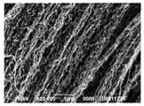
- FIG. 2 is a scanning electron micrograph of the carbon fiber produced in Example 1.
- FIG. 2 is a scanning electron micrograph of the carbon fiber produced in Example 1.
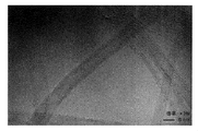
- FIG. 2 is a transmission electron micrograph of carbon fibers produced in Example 1.
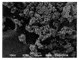
- FIG. 2 is a scanning electron micrograph of the carbon fiber produced in Comparative Example 1.
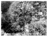
- 2 is a scanning electron micrograph of the carbon fiber produced in Comparative Example 1.
- the method for producing carbon fiber of the present invention includes contacting a supported catalyst and a carbon atom-containing compound in a heating zone.
- the supported catalyst used in the present invention is obtained by a method including impregnating a powdered carrier with a colloid containing a catalyst and supporting the catalyst particles on the powdered carrier.
- the powdery carrier used for the supported catalyst in the present invention preferably has a specific crystal plane developed. Whether or not such a specific crystal plane is developed can be determined by comparing with, for example, X-ray diffraction data of (isotropic) powder.
- X-ray diffraction data of (isotropic) powder is published in JCPDS (Joint Committee on Powder Diffraction Standards) and the like. According to JCPDS, for example, in magnesia, the ratio (I 1s / I 2s ) of the peak intensity I 1s derived from the (200) plane to the peak intensity I 2s derived from the (220) plane is 2.6 (No 45-946).
- Alumina has a ratio (I 1s / I 2s ) of the peak intensity I 1s derived from the (104) plane to the peak intensity I 2s derived from the (116) plane of 1.1 (No. 1212-46).
- the ratio (I 1s / I 2s ) of the peak intensity I 1s derived from the (113) plane and the peak intensity I 2s derived from the (116) plane is 1.3 (10-173).
- Calcia has a ratio (I 1s / I 2s ) of the peak intensity I 1s derived from the (200) plane to the peak intensity I 2s derived from the (111) plane from 2.5 (48-1467) to 2.7. (37-1497).
- the numbers in parentheses are JCPDS card numbers. I 1s indicates the intensity of the strongest peak among the peaks described in JCPDS, and I 2s indicates the intensity of the second strongest peak among the peaks described in JCPDS.
- the ratio of the most intense peak intensity I 1 observed in the powder X-ray diffraction and the second most intense peaks of the intensity I 2 Is larger than the ratio (I 1s / I 2s ) of the strongest peak intensity I 1s described in JCPDS to the second strongest peak intensity I 2s , preferably the strongest peak intensity described in JCPDS More than 1.5 times the ratio (I 1s / I 2s ) of I 1s to the second strongest peak intensity I 2s , more preferably the strongest peak intensity I 1s and the second strongest as described in JCPDS It is one that is at least twice the ratio (I 1s / I 2s ) with the peak intensity I 2s .
- I 1 indicates the intensity of the strongest peak among the measured peaks
- I 2 indicates the intensity of the second strongest peak among the measured peaks.
- the ratio of the intensity I 1 and the peak intensity I 2 derived from the (220) plane (I 1 / I 2 ); the peak intensity I 1 derived from the (104) plane of alumina and the peak derived from the (116) plane
- Ratio of intensity I 2 (I 1 / I 2 ); ratio of peak intensity I 1 derived from the (113) plane of alumina to peak intensity I 2 derived from the (116) plane (I 1 / I 2 )
- the ratio of the strongest peak of the intensity I 1 and the second strong peak intensity I 2 that is observed in the powder X-ray diffraction is , Preferably 4 or more, more preferably 5 or more, and even more preferably 6 or more. If the peak intensity ratio (I 1 / I 2 ) is too small, desired conductivity or thermal conductivity tends to be difficult to obtain.
- the peak showing the strongest intensity I 1 observed in X-ray diffraction is preferably derived from the (200) plane, and the second strongest intensity I 2 is shown.
- the peak is preferably derived from the (220) plane.
- the powdery carrier is not limited depending on the chemical species constituting it.
- chemical species include oxides such as alumina, zirconia, magnesia, silica, and calcia; and nitrides such as aluminum nitride.
- magnesium oxide is preferable, and electrofused magnesia, that is, magnesia produced by an electric melting method is more preferable.
- the powdery carrier has a particle size of preferably 1 to 5000 ⁇ m, more preferably 10 to 500 ⁇ m, still more preferably 40 to 200 ⁇ m.
- the particle size of the powdery carrier can be confirmed by sieving.
- the powdery carrier preferably has a specific surface area smaller than that generally used in the field. Specifically, the specific surface area of the powdery carrier is preferably 1 to 10 m 2 / g, more preferably 1.5 to 3 m 2 / g.
- the powdery carrier has a bulk density (measured in accordance with JIS Z-2512 (tap density measurement method)) of preferably 0.8 to 3 g / cm 3 , more preferably 1 to 2.5 g / cm 2 . cm 3 .
- the method for obtaining the powdery carrier is not particularly limited.
- it can be obtained by an electric melting method. It can also be obtained from commercially available powder carriers.
- the catalyst colloid used for the preparation of the supported catalyst is obtained by dispersing a fine catalyst in a liquid medium.
- the particle size of the catalyst in the catalyst colloid is not particularly limited, but is preferably 1 to 100 nm, more preferably 1 to 50 nm, and still more preferably 1 to 20 nm.
- the particle diameter of the catalyst in the catalyst colloid is an average diameter obtained from an image observed with a transmission electron microscope (TEM).
- the concentration of the catalyst particles contained in the catalyst colloid is preferably 0.1 to 5% by mass, more preferably 0.5 to 3% by mass.
- the concentration is too high, the viscosity of the catalyst colloid becomes high, so that there is a tendency that handling when carrying on a powdery carrier becomes inconvenient. If the concentration is too low, the number of steps for obtaining a desired loading amount tends to increase.
- the catalyst colloid is not particularly limited by its preparation method.
- a method of preparing a colloid in which fine metal fine particles are dispersed by thermally decomposing metal carbonyl or the like in a liquid medium in which a surfactant is present, or a metal catalyst source and hydrogen in a liquid medium in which a surfactant is present is present.
- a method of preparing a colloid in which fine metal particles are dispersed by reacting with a reducing agent such as sodium borohydride or lithium borohydride, or a polar solvent in which a metal catalyst source is dissolved is nonpolar in the presence of a surfactant. Examples thereof include a method of preparing a colloid in which metal fine particles are dispersed by substitution with a solvent (microemulsion method).
- the catalyst colloid is preferably prepared from two or more kinds of metal halides having different valences which serve as catalyst sources in the presence of a surfactant. More specifically, the catalyst colloid includes heat-treating in a liquid medium two or more metal halides having different valences as a catalyst source and a surfactant having 8 or more carbon atoms, and then purifying. It is preferable to obtain by a method.
- the upper limit of the heating temperature is preferably a temperature that is 10 ° C. lower than the boiling point of the liquid medium, more preferably a temperature that is 20 ° C. lower than the boiling point of the liquid medium. According to such a preparation method, the catalyst colloid can be obtained under the preparation conditions at a low temperature, specifically, at 100 ° C. or lower, so that the manufacturing cost can be kept low.
- the surfactant used in the preparation of the catalyst colloid is not particularly limited, but a surfactant that can suppress the aggregation of the catalyst particles and contribute to the preparation of catalyst particles having a narrow particle size distribution is preferable. Specifically, a surfactant having 8 or more carbon atoms is preferable.
- a surfactant having 8 or more carbon atoms is preferable.
- an anionic surfactant, a cationic surfactant, or a nonionic surfactant can be used.
- the anionic surfactant include a carboxylate type surfactant, a sulfonate type surfactant, a sulfate ester type surfactant, and a phosphate ester type surfactant.
- Examples of the cationic surfactant include a quaternary ammonium salt type surfactant and an amine salt type surfactant.
- Examples of nonionic surfactants include polyethylene glycol type surfactants, polyhydric alcohol fatty acid ester type surfactants, higher alcohol type surfactants, and the like.
- alkali metal salts of higher fatty acids which are a kind of anionic surfactant, are preferred.
- higher fatty acid alkali metal salts having a long chain alkyl group having 8 to 22 carbon atoms are preferred, and higher fatty acid alkali metals having a long chain alkyl group having 12 to 20 carbon atoms.
- a salt is more preferred.
- examples include potassium acid, sodium linoleate, and potassium linoleate.
- free fatty acids such as caprylic acid, lauric acid, myristic acid, palmitic acid, stearic acid, oleic acid, linoleic acid and alkaline substances May be used in combination.
- the concentration of the surfactant during preparation of the catalyst colloid is preferably 1 to 50% by mass, more preferably 10 to 30% by mass.
- the liquid medium used for preparing the catalyst colloid is not particularly limited as long as the catalyst particles can be uniformly dispersed.
- examples thereof include water and organic solvents such as alcohol, ketone, ester, and hydrocarbon.
- organic solvent having a low polarity is preferable.
- examples of the organic solvent having low polarity include pentane, hexane, benzene, toluene, diethyl ether, ethyl acetate, methylene chloride, chloroform and the like.
- the liquid medium has a boiling point of preferably 150 ° C. or less, more preferably 20 ° C.
- a boiling point examples include hexane, benzene, toluene, methylene chloride, chloroform, and ethyl acetate.
- a low-viscosity solvent is preferable from the viewpoint of easy wettability to the catalyst carrier. Examples of the low viscosity solvent include pentane, hexane, and diethyl ether. Therefore, hexane can be mentioned as a liquid medium having these conditions.
- the catalyst source used for the preparation of the catalyst colloid is not particularly limited as long as it is a substance that promotes the growth of carbon fibers.
- the catalyst source include at least one metal element selected from the group consisting of groups 3 to 12 in the group 18 element periodic table recommended by IUPAC in 1990.
- at least one metal element selected from the group consisting of 3, 5, 6, 8, 9, and 10 groups is preferable, and iron, cobalt, nickel, chromium, molybdenum, tungsten, vanadium, titanium, ruthenium, and rhodium are preferable.
- At least one metal element selected from the group consisting of palladium, platinum and rare earth elements is particularly preferred.
- compounds containing metal elements that act as catalysts include inorganic salts such as nitrates, sulfates and halides, organic salts such as acetates, organic complexes such as acetylacetone complexes, and organic metals.
- inorganic salts such as nitrates, sulfates and halides
- organic salts such as acetates
- organic complexes such as acetylacetone complexes
- organic metals A compound etc. can be mentioned.
- halides are preferred from the viewpoints of reactivity and difficulty in remaining after the reaction, and easy purification.
- the reaction activity can be adjusted by using two or more of these catalyst sources.
- the combination of catalyst sources it is possible to select preferably two or more metal compounds having different valences, more preferably two or more metal halides having different valences.
- suitable combinations of catalyst sources are disclosed in JP-A-2008-174442. Specifically, a combination of an element selected from Fe, Co, and Ni, an element selected from Ti, V, and Cr and an element selected from Mo and W can be given as a preferable example.
- the catalyst colloid is preferably a catalyst colloid from which excess surfactants and the like that are not preferable in the catalyst carrier and carbon nanotube synthesis are removed by purification.
- the purification method is not particularly limited. Examples thereof include a physical purification method using an ultra filter membrane and a purification method using decantation. The following can be mentioned as one form of a more specific purification method. First, an appropriate amount of polar solvent is added to and mixed with the catalyst colloid obtained by the above preparation method. Then, it separates into a catalyst precipitation layer and a supernatant liquid layer by gravity or centrifugal force.
- An appropriate amount of a polar solvent is further added to the collected supernatant and separated into a catalyst precipitation layer and a supernatant liquid layer by gravity or centrifugal force. This operation is repeated a plurality of times, preferably 2 to 3 times.
- the catalyst precipitation layers separated by the above operation are combined into one, and then a liquid medium is added and dispersed. By these operations, a catalyst colloid from which excess surfactant and the like are removed is obtained.
- the catalyst carrier is supported on the powder carrier by impregnating the powder carrier with the catalyst colloid.
- the procedure for impregnation is not particularly limited.
- the catalyst colloid in an amount corresponding to the liquid absorption amount of the carrier may be dropped onto the powder carrier and then dried; the catalyst colloid and the powder carrier are mixed in a predetermined amount, and then the mixture is mixed. It may be dried. Further, the dropping or mixing step and the drying step may be repeated until a predetermined loading amount is reached.
- the drying may be performed under conditions sufficient for the used liquid medium to volatilize, and may be dried by heating to about the boiling point temperature of the liquid medium.
- the amount of catalyst particles supported is not particularly limited, but if the amount supported is too large, the supported catalyst particles tend to aggregate, resulting in a decrease in carbon fiber productivity, and the resulting carbon fiber is derived from a supported catalyst. Since many impurities are likely to be contained, when the carbon fiber is blended with a resin or the like, the impurities tend to affect properties such as conductivity. On the other hand, when the loading amount is too small, the progress of the carbon fiber generation reaction is delayed, and the productivity tends to be lowered.
- the amount of catalyst particles supported (in terms of molar amount of catalyst metal element) varies depending on the type of powder carrier and catalyst colloid used, the method of loading, etc., but preferably 5 ⁇ 10 ⁇ 4 per surface area of the powder carrier.
- mol / m 2 or less more preferably 1 ⁇ 10 ⁇ 6 mol / m 2 or more and 5 ⁇ 10 ⁇ 4 mol / m 2 or less, still more preferably 1 ⁇ 10 ⁇ 6 mol / m 2 or more and 3 ⁇ 10 ⁇ 4 mol / m 2.
- m 2 or less even more preferably 1 ⁇ 10 ⁇ 6 mol / m 2 or more and 1 ⁇ 10 ⁇ 4 mol / m 2 or less, particularly preferably 1 ⁇ 10 ⁇ 6 mol / m 2 or more and 1 ⁇ 10 ⁇ 5 mol / m 2 or less. 2 or less.
- the catalyst particles supported on the carrier may be reduced by bringing a reducing gas into contact with the supported catalyst.
- the reducing gas include a gas containing hydrogen.
- the supported catalyst is allowed to stay in the heating zone for an excessively long time before contacting the supported catalyst according to the present invention with the carbon atom-containing compound, the desired effect may not be obtained. Therefore, when the supported catalyst is placed in the reaction furnace and then heated, it is preferable to increase the heating rate and immediately contact the carbon atom-containing compound after reaching the predetermined temperature. Moreover, it is preferable that the supported catalyst and the carbon atom-containing compound are simultaneously supplied to the reaction furnace after the temperature of the reaction furnace is increased to a predetermined temperature.
- Carbon atom-containing compounds The carbon atom containing compound used for this invention will not be specifically limited if it becomes a carbon source of carbon fiber.
- this carbon atom-containing compound all compounds such as CCl 4 , CHCl 3 , CH 2 Cl 2 , CH 3 Cl, CO, CO 2 and CS 2 can be used.
- Particularly useful compounds include CO, CO 2 , aliphatic hydrocarbons and aromatic hydrocarbons.
- carbon atom-containing compounds containing elements such as nitrogen, phosphorus, oxygen, sulfur, fluorine, chlorine, bromine and iodine.
- preferable carbon atom-containing compounds include inorganic gases such as CO and CO 2 ; alkanes such as methane, ethane, propane, butane, pentane, hexane, heptane, and octane; alkenes such as ethylene, propylene, and butadiene; Alkynes such as acetylene; monocyclic aromatic hydrocarbons such as benzene, toluene, xylene and styrene; polycyclic compounds having a condensed ring such as indene, naphthalene, anthracene and phenanthrene; cyclopropane, cyclopentane, cyclohexane, etc.
- inorganic gases such as CO and CO 2 ; alkanes such as methane, ethane, propane, butane, pentane, hexane, heptane, and octane; alkenes
- Examples include cycloparaffins; cycloolefins such as cyclopentene, cyclohexene, cyclopentadiene, and dicyclopentadiene; and alicyclic hydrocarbon compounds having a condensed ring such as a steroid.
- oxygen-containing atomic compounds such as methanol, ethanol, propanol, butanol, dimethyl ether, diethyl ether; methylthiol, methylethyl sulfide, Sulfur-containing aliphatic compounds such as dimethylthioketone; Sulfur-containing aromatic compounds such as phenylthiol and diphenylsulfide; Sulfur- and nitrogen-containing heterocyclic compounds such as pyridine, quinoline, benzothiophene, and thiophene; Mention may be made of halogenated hydrocarbons such as carbon chloride, chloroethane and trichloroethylene.
- compositions containing carbon atom-containing compounds such as natural gas, gasoline, kerosene, heavy oil, creosote oil, kerosene, turpentine oil, camphor oil, pine oil, gear oil, cylinder oil and the like. These can be used alone or in combination of two or more. Of these, CO, methane, ethane, propane, butane, ethylene, propylene, butadiene, methanol, ethanol, propanol, butanol, acetylene, benzene, toluene, xylene, or a mixture of any combination thereof is preferred.
- a carrier gas can be used to bring the aforementioned supported catalyst into contact with the aforementioned carbon atom-containing compound in the heating zone.
- This carrier gas is preferably introduced into the heating zone together with the aforementioned carbon atom-containing compound.
- the carrier gas include hydrogen, nitrogen, helium, argon, krypton, or a mixed gas thereof.
- carbon dioxide can be used as the carrier gas.
- a gas containing oxygen molecules (O 2 ) such as air is not suitable.
- a gas containing hydrogen is preferable as the carrier gas.
- the hydrogen content in the gas is preferably 1% by volume or more, more preferably 30% by volume or more, and still more preferably 85% by volume or more.
- Nitrogen etc. can be mentioned as gas which can be made to coexist with the gas containing hydrogen.
- the carbon atom-containing compound is liquid at normal temperature and solid, and then introduced into the heating zone after being vaporized by heating.
- the supply amount of the carbon atom-containing compound gas varies depending on the supported catalyst used, the carbon atom-containing compound, and the reaction conditions. Therefore, it cannot be uniquely determined, but (carbon atom-containing compound gas flow rate) / (carrier gas flow rate +
- the volume-based percentage of the carbon atom-containing compound gas flow rate is preferably 10 to 90% by volume, more preferably 30 to 70% by volume. For example, when the carbon atom-containing compound is ethylene, the range of 30 to 90% by volume is preferable.
- the temperature in the heating zone varies depending on the type of carbon atom-containing compound used, but is preferably 400 to 1100 ° C, more preferably 500 to 800 ° C, and still more preferably 700 to 800 ° C. If the temperature is too low or too high, the amount of carbon fiber produced tends to decrease. Moreover, when it becomes high temperature, a nonelectroconductive substance byproduces and there exists a tendency for it to adhere to the carbon fiber surface. Such carbon fibers may not be suitable for filler applications.
- Preferred carbon fibers obtained by the production method of the present invention are those having a cavity in the center of the fiber, that is, a so-called tube structure.
- the cavities may be continuous in the fiber longitudinal direction, or the cavities may be closed in the middle to be discontinuous.
- the preferable carbon fiber obtained by the manufacturing method of this invention is a graphene surface extended
- substantially parallel means that the inclination of the graphene surface with respect to the fiber axis is within about ⁇ 15 degrees.
- Carbon fibers having only one graphene layer so-called single-walled carbon nanotubes, have high surface energy and relatively low dispersibility in resins and the like, and therefore tend to have a small effect of imparting conductivity.
- the carbon fiber is preferably a carbon fiber having two graphene layers, so-called double wall carbon nanotubes, or a carbon fiber having three or more graphene layers, so-called multi-wall carbon nanotubes. Carbon nanotubes are particularly preferred.
- the carbon fiber obtained by the production method of the present invention preferably has a smaller fiber diameter from the viewpoint of high conductivity imparting effect.
- the upper limit of the fiber diameter d is preferably 100 nm, more preferably 50 nm, and particularly preferably 20 nm.
- the lower limit of the fiber diameter d is preferably 1 nm, more preferably 2 nm, and even more preferably 4 nm. Therefore, when considering the dispersibility and the conductivity imparting effect, the fiber diameter d is preferably 2 to 20 nm, and more preferably 4 to 20 nm.
- the inner diameter d 0 of the cavity is not particularly limited, but is preferably 0.1 to 90 nm.
- the ratio (d 0 / d) between the inner diameter d 0 and the fiber diameter (outer diameter) d is not particularly limited, but is preferably 0.1 to 0.9, more preferably 0.3 to 0.9, Preferably, it is 0.6 to 0.9.
- the fiber diameter d and the cavity inner diameter d 0 are an average outer diameter and an average inner diameter measured based on an image observed with a transmission electron microscope (TEM).
- the carbon fiber of the preferred embodiment according to the present invention is characterized by being twisted and curved, unlike the linear fiber as seen in the prior art.
- the adhesion with the matrix material is increased and the interface strength is increased as compared with the conventional linear carbon fiber, so that the deterioration of the mechanical properties of the composite material can be suppressed.
- the carbon fiber according to a preferred embodiment of the present invention has a curved shape, but the fibers themselves are aligned in the same direction, and are stretched in the same direction to form a band or ribbon as an aggregate. (See FIGS. 1 and 2).
- the carbon fibers according to the present invention are agglomerated in a state where the respective fiber axes are substantially parallel to each other, so that the degree of entanglement between the fibers is low, and good dispersibility can be given. It is done.
- carbon fibers obtained using a general high specific surface area catalyst support are mixed with amorphous materials, the fibers themselves are linear and largely curved, and the fibers are random. Since it grows in the direction, it becomes an amorphous aggregate or a nearly spherical aggregate, and the fibers are intertwined very firmly and become an agglomerate that is difficult to unravel (see FIGS. 4 and 5). Therefore, there exists a tendency for the electroconductivity provision effect to a resin composite material to be small.
- the carbon fiber according to the present invention can be made into a composite material by blending into a matrix material and kneading.
- the amount of carbon fiber contained in the composite material is preferably 0.5 to 30% by mass, more preferably 0.5 to 10% by weight, and still more preferably 0.5 to 5% by weight.
- the effect which provides sufficient electroconductivity and heat conductivity to a composite material will be small. If the carbon fiber content is too large, the properties of the matrix material tend to be impaired.
- the matrix material that can be used for the composite material is not particularly limited, but a resin is preferable.
- a resin is preferable.
- the resin to be the matrix material any of a thermosetting resin, a photocurable resin, or a thermoplastic resin can be used.
- the thermosetting resin include polyamide, polyether, polyimide, polysulfone, epoxy resin, unsaturated polyester resin, and phenol resin.
- the thermoplastic resin include nylon resin, polyethylene resin, polyamide resin, polyester resin, polycarbonate resin, and polyarylate resin.
- the composite material containing the carbon fiber according to the present invention is a product required to have conductivity and antistatic properties as well as impact resistance, such as OA equipment, electronic equipment, conductive packaging parts, conductive sliding members, It is suitable as a molding material for conductive heat conductive members, antistatic packaging parts, and automobile parts to which electrostatic coating is applied.
- a conventionally known molding method can be used. Examples of the molding method include an injection molding method, a hollow molding method, an extrusion molding method, a sheet molding method, a thermoforming method, a rotational molding method, a laminate molding method, and a transfer molding method.
- the carbon fiber which concerns on this invention can be used for various electrode materials.
- the carbon fiber according to the present invention is compounded with various electrode materials based on the methods disclosed in Japanese Patent Nos. 3960973, 3722965, 3618492, and 4031309, thereby providing conductivity, electrode strength, battery The characteristics can be improved.
- the reagents used are as follows. Iron (III) chloride hexahydrate (special grade reagent manufactured by Junsei Co., Ltd.) Iron (II) chloride tetrahydrate (special grade reagent manufactured by Wako Pure Chemical Industries, Ltd.) Sodium oleate (Wako Pure Chemical Industries, Ltd.) Electrofused magnesia KMAO (manufactured by Tateho Chemical Industry Co., Ltd.) Magnesia 500A (manufactured by Ube Materials) Magnesia (Kishida Chemical Co., Ltd.) Sintered magnesia RA (manufactured by Tateho Chemical Co., Ltd.) Fused magnesia KMAOH-F (manufactured by Tateho Chemical Industry Co., Ltd.)
- the specific surface area was calculated by the BET method by determining the amount of nitrogen gas adsorbed at a liquid nitrogen temperature (77 K) using NOVA1000 manufactured by Yuasa Ionics.
- the bulk density was measured according to JIS Z-2512 (tap density measurement method).
- a powder X-ray diffraction sample was prepared by adding a powder carrier to a sample holder of a glass sample plate little by little and holding it with glass so that the sample holder was uniform and the sample surface was the same as the sample plate.
- X-ray diffractometer X-ray Diffractometer Rigaku Geigerflex (manufactured by Rigaku Corporation) is used, CuK ⁇ 1 is used as an X-ray source, output is 40 kV-30 mA, scan speed is 2 ° / min, and measurement range is 20 ° -80 °. did. It was determined strongest peak ratio of the intensity I 2 of the intensity I 1 and the second strong peaks of (1st peak) (2nd peak) (I 1 / I 2).
- Example 1 [Preparation of catalyst colloid] Under a nitrogen atmosphere, 0.36 g of iron (III) chloride hexahydrate and 0.13 g of iron (II) chloride tetrahydrate were dissolved in a mixed solution of 4 ml of ethanol, 3 ml of distilled water and 7 ml of toluene. While stirring this solution, 1.62 g of sodium oleate was added and refluxed in an oil bath at 74 ° C. for 4 hours. After cooling to room temperature, 20 mL of ethanol was added, and centrifugation (5,000 rpm ⁇ 10 minutes) was performed to separate the solid and liquid. The liquid was separated and the remaining solid was dispersed in 20 mL of hexane.
- the solid hexane dispersions obtained by the above operations were combined and used as catalyst colloids.
- the catalyst particles in the catalyst colloid had a particle diameter of 4 to 6 nm as observed by transmission electron microscope (TEM).
- the catalyst particles were confirmed to be Fe 3 O 4 by X-ray diffraction.
- Electrofused magnesia KMAO was sieved to a particle size of 20-45 ⁇ m. This was used as powder carrier A. The characteristics of the carrier are shown in Table 1.
- the catalyst colloid corresponding to the amount of liquid absorbed by the carrier was dropped onto the powder carrier A. Thereafter, it was dried at room temperature to obtain a supported catalyst.
- the amount of Fe supported per unit surface area of the powdery support was 2.7 ⁇ 10 ⁇ 5 mol / m 2 .
- the carbon fiber itself had a winding and curved shape.
- the carbon fibers are aggregated in a state of being arranged substantially in parallel along the fiber axis, and the aggregate includes a shape like a band or a ribbon. It was.
- FIG. 3 shows a transmission electron microscope (TEM) photograph of the generated carbon fiber.
- the obtained carbon fiber had a tube structure.
- the fiber diameter (outer diameter d) was 6 nm
- the inner diameter d 0 was 4 nm
- the outer diameter / inner diameter ratio was 1.5. 39 g of carbon fiber was produced per 1 g of Fe in the supported catalyst used in this reaction.
- Example 2 Electrofused magnesia KMAO was sieved to a particle size of 45-150 ⁇ m. This was used as powder carrier B. The characteristics of the carrier are shown in Table 1.
- the supported catalyst was changed in the same manner as in Example 1 except that the powder carrier A was changed to the powder carrier B and the Fe support amount per unit surface area of the powder carrier was changed to 5.7 ⁇ 10 ⁇ 6 mol / m 2.
- carbon fiber was produced.
- a carbon fiber similar to the carbon fiber obtained in Example 1 was produced.
- the carbon fiber obtained in Example 2 has a shape in which the carbon fiber itself is twisted and curved, but the carbon fibers are aggregates in a state of being aligned substantially in parallel along the fiber axis. Agglomerates that were shaped like bands or ribbons were included. 384 g of carbon fiber was produced per 1 g of Fe in the supported catalyst used in this reaction.
- Comparative Example 2 A supported catalyst was prepared in the same manner as in Example 1 except that the catalyst colloid was changed to the catalyst solution prepared in Comparative Example 1, and carbon fibers were produced. A carbon fiber similar to the carbon fiber obtained in Comparative Example 1 was produced. The carbon fiber obtained in Comparative Example 2 contains a mixture of amorphous materials, the fiber itself is linear and greatly curved, and the fibers are growing in a random direction and are difficult to unravel. It was an agglomerate in a different state. 25 g of carbon fiber was produced per 1 g of Fe in the supported catalyst used in this reaction.
- Comparative Example 3 Magnesia manufactured by Kishida Chemical Co. was used as the powdery carrier D. The characteristics of the carrier are shown in Table 1.
- a supported catalyst was prepared in the same manner as in Example 1 except that the powder carrier A was changed to the powder carrier D to produce carbon fibers.
- a carbon fiber similar to the carbon fiber obtained in Comparative Example 1 was produced.
- the carbon fiber obtained in Comparative Example 3 contains a mixture of amorphous substances, the fiber itself is linear and greatly curved, and the fibers are growing in random directions and are difficult to unravel. It was an agglomerate in a different state. 33 g of carbon fiber was produced per 1 g of Fe in the supported catalyst used in this reaction.
- Comparative Example 4 Sintered magnesia RA (manufactured by Tateho Chemical Co., Ltd.) was used as the powder carrier E. The characteristics of the carrier are shown in Table 1.
- a supported catalyst was prepared in the same manner as in Example 1 except that the powder carrier A was changed to the powder carrier E, and carbon fibers were produced.
- a carbon fiber similar to the carbon fiber obtained in Comparative Example 1 was produced.
- the carbon fiber obtained in Comparative Example 4 contains a mixture of amorphous substances, the fiber itself is linear and greatly curved, and the fibers are growing in a random direction and are difficult to unravel. It was an agglomerate in a different state. 13 g of carbon fiber was produced per 1 g of Fe in the supported catalyst used in this reaction.
- Comparative Example 5 Electrofused magnesia KMAOH-F (manufactured by Tateho Chemical Industry Co., Ltd.) was used as the powder carrier F. The characteristics of the carrier are shown in Table 1.
- a supported catalyst was prepared in the same manner as in Example 1 except that the powder carrier A was changed to the powder carrier F to produce carbon fibers.
- a carbon fiber similar to the carbon fiber obtained in Comparative Example 1 was produced.
- the carbon fiber obtained in Comparative Example 5 is difficult to unravel, in which irregularly shaped substances are mixed, the fiber itself is linear and greatly curved, and the fibers are growing in random directions. It was an agglomerate in a different state. 1 g of carbon fiber was produced per 1 g of Fe in the supported catalyst used in this reaction.
- Example 1 1 part by mass of the carbon fiber obtained in Example 1 and Comparative Examples 1 and 3 and 9 parts by mass of a cycloolefin polymer (ZEONOR 1420R manufactured by Nippon Zeon Co., Ltd.) were used using a Labo Plast Mill (Model 30C150 manufactured by Toyo Seiki Seisakusho)
- the composite material was obtained by kneading at a temperature of 80 ° C. for 10 minutes. This composite material was hot-pressed under the conditions of 280 ° C., 50 MPa, and 60 seconds to produce a flat plate of 100 mm ⁇ 100 mm ⁇ 2 mm. About the said flat plate, the volume resistivity was measured using the resistivity meter (Mitsubishi Chemical Corporation Loresta GP and Hiresta UP). The results are shown in Table 2.
- powdered carrier in which a specific crystal plane is developed for example, the ratio of the strongest peak intensity I 1 and the intensity I 2 of the strongest peak in the second observed X-ray diffraction (I 1 / I 2 )
- the ratio of the strongest peak intensity I 1 observed in X-ray diffraction to the second strongest peak intensity I 2 is the highest in JCPDS.
- the catalyst is impregnated with a colloid containing a catalyst on a powdery carrier that is 1.5 times or more the ratio (I 1s / I 2s ) of the intensity I 1s of the strong peak and the intensity I 2s of the second strongest peak.
Landscapes
- Chemical & Material Sciences (AREA)
- Engineering & Computer Science (AREA)
- Organic Chemistry (AREA)
- Materials Engineering (AREA)
- Chemical Kinetics & Catalysis (AREA)
- Nanotechnology (AREA)
- Physics & Mathematics (AREA)
- Inorganic Chemistry (AREA)
- Condensed Matter Physics & Semiconductors (AREA)
- General Physics & Mathematics (AREA)
- Crystallography & Structural Chemistry (AREA)
- Textile Engineering (AREA)
- Thermal Sciences (AREA)
- General Chemical & Material Sciences (AREA)
- Manufacturing & Machinery (AREA)
- Composite Materials (AREA)
- Catalysts (AREA)
- Inorganic Fibers (AREA)
- Carbon And Carbon Compounds (AREA)
- Dispersion Chemistry (AREA)
Priority Applications (5)
| Application Number | Priority Date | Filing Date | Title |
|---|---|---|---|
| JP2011527092A JP4852671B2 (ja) | 2010-03-02 | 2011-03-02 | 炭素繊維の製造方法 |
| EP11750382.1A EP2543756A4 (en) | 2010-03-02 | 2011-03-02 | PROCESS FOR PRODUCING CARBON FIBERS |
| CN201180011873.7A CN102782197B (zh) | 2010-03-02 | 2011-03-02 | 碳纤维的制造方法 |
| KR1020127013212A KR101543682B1 (ko) | 2010-03-02 | 2011-03-02 | 탄소 섬유의 제조 방법 |
| US13/582,273 US8992879B2 (en) | 2010-03-02 | 2011-03-02 | Method of producing carbon fiber |
Applications Claiming Priority (2)
| Application Number | Priority Date | Filing Date | Title |
|---|---|---|---|
| JP2010-044963 | 2010-03-02 | ||
| JP2010044963 | 2010-03-02 |
Publications (1)
| Publication Number | Publication Date |
|---|---|
| WO2011108269A1 true WO2011108269A1 (ja) | 2011-09-09 |
Family
ID=44541938
Family Applications (1)
| Application Number | Title | Priority Date | Filing Date |
|---|---|---|---|
| PCT/JP2011/001233 WO2011108269A1 (ja) | 2010-03-02 | 2011-03-02 | 炭素繊維の製造方法 |
Country Status (6)
| Country | Link |
|---|---|
| US (1) | US8992879B2 (zh) |
| EP (1) | EP2543756A4 (zh) |
| JP (2) | JP4852671B2 (zh) |
| KR (1) | KR101543682B1 (zh) |
| CN (1) | CN102782197B (zh) |
| WO (1) | WO2011108269A1 (zh) |
Cited By (4)
| Publication number | Priority date | Publication date | Assignee | Title |
|---|---|---|---|---|
| JP2012031015A (ja) * | 2010-07-30 | 2012-02-16 | Toray Ind Inc | カーボンナノチューブ製造法 |
| WO2014185291A1 (ja) * | 2013-05-13 | 2014-11-20 | イーグル工業株式会社 | Ptfe樹脂組成物 |
| CN104445140A (zh) * | 2014-11-05 | 2015-03-25 | 华文蔚 | 一种碳纳米管的制造方法 |
| WO2016152105A1 (ja) * | 2015-03-25 | 2016-09-29 | 日本ゼオン株式会社 | 炭素ナノ構造体の製造方法 |
Families Citing this family (6)
| Publication number | Priority date | Publication date | Assignee | Title |
|---|---|---|---|---|
| JP5649269B2 (ja) * | 2008-06-18 | 2015-01-07 | 昭和電工株式会社 | カーボンナノファイバー、その製造方法及び用途 |
| JP5852531B2 (ja) * | 2012-09-12 | 2016-02-03 | 東芝環境ソリューション株式会社 | 金属微粒子の回収方法および回収装置 |
| JP2015044718A (ja) * | 2013-08-29 | 2015-03-12 | デュポン株式会社 | 熱伝導性粒子の製造方法 |
| CN105939834B (zh) * | 2013-12-13 | 2019-03-29 | 伍德韦尔丁公司 | 用于加强和/或加衬材料的方法 |
| KR102291933B1 (ko) * | 2014-02-05 | 2021-08-19 | 덴카 주식회사 | 카본 나노파이버의 제조방법 및 카본 나노파이버 |
| WO2021060419A1 (ja) * | 2019-09-27 | 2021-04-01 | 日本ゼオン株式会社 | 触媒担持体の製造方法および繊維状炭素ナノ構造体の製造方法 |
Citations (14)
| Publication number | Priority date | Publication date | Assignee | Title |
|---|---|---|---|---|
| JPS57127449A (en) * | 1981-01-29 | 1982-08-07 | Agency Of Ind Science & Technol | Manufacture of solid catalyst carried in a colloidal form |
| JPH0431009B2 (zh) | 1987-10-08 | 1992-05-25 | ||
| JP2001062299A (ja) | 1999-08-31 | 2001-03-13 | Agency Of Ind Science & Technol | カーボンナノチューブ合成用触媒液 |
| JP2003073930A (ja) | 2001-08-31 | 2003-03-12 | Showa Denko Kk | 微細炭素繊維及びその製造方法 |
| JP2003171832A (ja) | 2001-12-11 | 2003-06-20 | Showa Denko Kk | 炭素繊維の合成用原料組成物、それを用いた炭素繊維の製造方法および炭素繊維 |
| JP2004534715A (ja) * | 2001-07-20 | 2004-11-18 | ケイエイチ ケミカルズ カンパニー、リミテッド | カーボンナノチューブの製造方法 |
| JP3618492B2 (ja) | 1996-11-29 | 2005-02-09 | 昭和電工株式会社 | 電池用電極材および二次電池 |
| JP3722965B2 (ja) | 1997-10-22 | 2005-11-30 | 昭和電工株式会社 | 電気二重層コンデンサ用炭素材料 |
| WO2007074629A1 (ja) | 2005-12-29 | 2007-07-05 | Toray Industries, Inc. | カーボンナノチューブの製造方法およびカーボンナノチューブ製造用触媒 |
| JP3960973B2 (ja) | 2001-01-16 | 2007-08-15 | 昭和電工株式会社 | 電池用触媒組成物、ガス拡散層及びこれらを備えた燃料電池 |
| JP2007268319A (ja) | 2006-03-08 | 2007-10-18 | Toyota Central Res & Dev Lab Inc | カーボンナノチューブ合成用触媒及びその製造方法、触媒分散液、並びに、カーボンナノチューブの製造方法 |
| JP2008133177A (ja) | 2006-10-26 | 2008-06-12 | Kurosaki Harima Corp | ナノカーボン被覆耐火原料とのその製造方法、およびそれを使用した耐火物とその製造方法 |
| JP2008169092A (ja) | 2007-01-12 | 2008-07-24 | National Institute Of Advanced Industrial & Technology | カーボンナノチューブの製造方法 |
| JP2008174442A (ja) | 2006-12-21 | 2008-07-31 | Showa Denko Kk | 炭素繊維および炭素繊維製造用触媒 |
Family Cites Families (9)
| Publication number | Priority date | Publication date | Assignee | Title |
|---|---|---|---|---|
| EP1154050A1 (en) * | 2000-05-13 | 2001-11-14 | Korean Carbon Black Co., Ltd., Degussa Group | Carbon fibrils and method for producing same |
| GB0216654D0 (en) * | 2002-07-17 | 2002-08-28 | Univ Cambridge Tech | CVD Synthesis of carbon nanoutubes |
| JP4761346B2 (ja) * | 2005-03-28 | 2011-08-31 | 国立大学法人名古屋大学 | 2層カーボンナノチューブ含有組成物 |
| JP4872042B2 (ja) * | 2005-05-10 | 2012-02-08 | 国立大学法人名古屋大学 | 高密度カーボンナノチューブ集合体及びその製造方法 |
| JP4834818B2 (ja) * | 2005-05-10 | 2011-12-14 | 国立大学法人名古屋大学 | カーボンナノチューブ集合体の製造方法 |
| DE102006055106C5 (de) * | 2006-11-14 | 2018-08-23 | Byk-Chemie Gmbh | Dispergierverfahren |
| JP4873413B2 (ja) * | 2006-11-15 | 2012-02-08 | ニッタ株式会社 | 多層カーボンナノチューブの集合構造 |
| DK2011907T3 (da) * | 2007-07-02 | 2010-05-17 | Centre Nat Rech Scient | Fremgangsmåde til fremstilling af hydrogengas og carbon-nanorør ud fra en katalytisk nedbrydning af ethanol |
| TW201012749A (en) * | 2008-08-19 | 2010-04-01 | Univ Rice William M | Methods for preparation of graphene nanoribbons from carbon nanotubes and compositions, thin films and devices derived therefrom |
-
2011
- 2011-03-02 CN CN201180011873.7A patent/CN102782197B/zh not_active Expired - Fee Related
- 2011-03-02 KR KR1020127013212A patent/KR101543682B1/ko active IP Right Grant
- 2011-03-02 JP JP2011527092A patent/JP4852671B2/ja not_active Expired - Fee Related
- 2011-03-02 WO PCT/JP2011/001233 patent/WO2011108269A1/ja active Application Filing
- 2011-03-02 US US13/582,273 patent/US8992879B2/en not_active Expired - Fee Related
- 2011-03-02 EP EP11750382.1A patent/EP2543756A4/en not_active Withdrawn
- 2011-10-24 JP JP2011233045A patent/JP2012052282A/ja active Pending
Patent Citations (15)
| Publication number | Priority date | Publication date | Assignee | Title |
|---|---|---|---|---|
| JPS57127449A (en) * | 1981-01-29 | 1982-08-07 | Agency Of Ind Science & Technol | Manufacture of solid catalyst carried in a colloidal form |
| JPH0431009B2 (zh) | 1987-10-08 | 1992-05-25 | ||
| JP3618492B2 (ja) | 1996-11-29 | 2005-02-09 | 昭和電工株式会社 | 電池用電極材および二次電池 |
| JP3722965B2 (ja) | 1997-10-22 | 2005-11-30 | 昭和電工株式会社 | 電気二重層コンデンサ用炭素材料 |
| JP2001062299A (ja) | 1999-08-31 | 2001-03-13 | Agency Of Ind Science & Technol | カーボンナノチューブ合成用触媒液 |
| JP3960973B2 (ja) | 2001-01-16 | 2007-08-15 | 昭和電工株式会社 | 電池用触媒組成物、ガス拡散層及びこれらを備えた燃料電池 |
| JP2004534715A (ja) * | 2001-07-20 | 2004-11-18 | ケイエイチ ケミカルズ カンパニー、リミテッド | カーボンナノチューブの製造方法 |
| JP2005225757A (ja) | 2001-07-20 | 2005-08-25 | Kh Chemicals Co Ltd | カーボンナノチューブの製造方法 |
| JP2003073930A (ja) | 2001-08-31 | 2003-03-12 | Showa Denko Kk | 微細炭素繊維及びその製造方法 |
| JP2003171832A (ja) | 2001-12-11 | 2003-06-20 | Showa Denko Kk | 炭素繊維の合成用原料組成物、それを用いた炭素繊維の製造方法および炭素繊維 |
| WO2007074629A1 (ja) | 2005-12-29 | 2007-07-05 | Toray Industries, Inc. | カーボンナノチューブの製造方法およびカーボンナノチューブ製造用触媒 |
| JP2007268319A (ja) | 2006-03-08 | 2007-10-18 | Toyota Central Res & Dev Lab Inc | カーボンナノチューブ合成用触媒及びその製造方法、触媒分散液、並びに、カーボンナノチューブの製造方法 |
| JP2008133177A (ja) | 2006-10-26 | 2008-06-12 | Kurosaki Harima Corp | ナノカーボン被覆耐火原料とのその製造方法、およびそれを使用した耐火物とその製造方法 |
| JP2008174442A (ja) | 2006-12-21 | 2008-07-31 | Showa Denko Kk | 炭素繊維および炭素繊維製造用触媒 |
| JP2008169092A (ja) | 2007-01-12 | 2008-07-24 | National Institute Of Advanced Industrial & Technology | カーボンナノチューブの製造方法 |
Non-Patent Citations (2)
| Title |
|---|
| J. PHYS. CHEM. B, vol. 108, 2004, pages 18908 |
| See also references of EP2543756A4 |
Cited By (5)
| Publication number | Priority date | Publication date | Assignee | Title |
|---|---|---|---|---|
| JP2012031015A (ja) * | 2010-07-30 | 2012-02-16 | Toray Ind Inc | カーボンナノチューブ製造法 |
| WO2014185291A1 (ja) * | 2013-05-13 | 2014-11-20 | イーグル工業株式会社 | Ptfe樹脂組成物 |
| CN104445140A (zh) * | 2014-11-05 | 2015-03-25 | 华文蔚 | 一种碳纳米管的制造方法 |
| WO2016152105A1 (ja) * | 2015-03-25 | 2016-09-29 | 日本ゼオン株式会社 | 炭素ナノ構造体の製造方法 |
| JPWO2016152105A1 (ja) * | 2015-03-25 | 2018-01-11 | 日本ゼオン株式会社 | 炭素ナノ構造体の製造方法 |
Also Published As
| Publication number | Publication date |
|---|---|
| CN102782197B (zh) | 2015-05-20 |
| JP2012052282A (ja) | 2012-03-15 |
| CN102782197A (zh) | 2012-11-14 |
| EP2543756A4 (en) | 2013-12-18 |
| KR20130004469A (ko) | 2013-01-10 |
| JPWO2011108269A1 (ja) | 2013-06-20 |
| US20120321543A1 (en) | 2012-12-20 |
| KR101543682B1 (ko) | 2015-08-11 |
| JP4852671B2 (ja) | 2012-01-11 |
| EP2543756A1 (en) | 2013-01-09 |
| US8992879B2 (en) | 2015-03-31 |
Similar Documents
| Publication | Publication Date | Title |
|---|---|---|
| JP4852671B2 (ja) | 炭素繊維の製造方法 | |
| Shen et al. | Ionic liquid-assisted one-step hydrothermal synthesis of TiO 2-reduced graphene oxide composites | |
| JP5634543B2 (ja) | 超低嵩密度のバンドル部分を有する高伝導性カーボンナノチューブ及びその製造方法 | |
| Lai et al. | Solvothermal syntheses of hollow carbon microspheres modified with–NH2 and–OH groups in one-step process | |
| JP5649269B2 (ja) | カーボンナノファイバー、その製造方法及び用途 | |
| KR101446116B1 (ko) | 탄소나노튜브 제조용 금속촉매의 제조방법 및 이를 이용한 탄소나노튜브의 제조방법 | |
| JP5242563B2 (ja) | カーボンナノファイバー、その製造方法及び用途 | |
| Yu et al. | Coating MWNTs with Cu2O of different morphology by a polyol process | |
| US7879261B2 (en) | Carbon nanofiber, production process and use | |
| JP5831966B2 (ja) | 単層カーボンナノチューブと二層カーボンナノチューブが任意比率で混合してなるカーボンナノチューブ集合体の製造方法 | |
| JP5653696B2 (ja) | 炭素繊維凝集体 | |
| JP5649901B2 (ja) | 多層カーボンナノチューブ集合体及びその製造方法 | |
| Németh et al. | Preparation of homogeneous titania coating on the surface of MWNT | |
| Li et al. | A high-performance Pt–Co bimetallic catalyst with polyethyleneimine decorated graphene oxide as support for hydrolysis of ammonia borane | |
| Huang et al. | Syntheses of carbon nanomaterials by ferrocene | |
| KR101231761B1 (ko) | 수직 배향된 번들 구조를 지닌 고전도성 탄소나노튜브 및 이를 이용한 고전도성 고분자 나노복합재 조성물 | |
| Sun et al. | Recent development of the synthesis and engineering applications of one-dimensional boron nitride nanomaterials | |
| Sun et al. | In situ reduction of iron oxide with graphene for convenient synthesis of various graphene hybrids | |
| KR20100134479A (ko) | 금속나노입자가 코팅된 탄소나노튜브 분말 및 그의 제조 방법 | |
| Cao et al. | Decorating Mg/Fe oxide nanotubes with nitrogen-doped carbon nanotubes | |
| El-Ahwany et al. | Chemical vapor deposition synthesis of high-quality Ni 3 C/GNPs composite material: Effect of growth time on the yield, morphology and adsorption behavior of metal ions | |
| Lu | Synthesis, characterization and applications of novel carbon and carbon-related nanomaterials | |
| Qian | Synthesis, purification and application of few-walled carbon nanotubes and inorganic nanowires |
Legal Events
| Date | Code | Title | Description |
|---|---|---|---|
| WWE | Wipo information: entry into national phase |
Ref document number: 201180011873.7 Country of ref document: CN |
|
| WWE | Wipo information: entry into national phase |
Ref document number: 2011527092 Country of ref document: JP |
|
| 121 | Ep: the epo has been informed by wipo that ep was designated in this application |
Ref document number: 11750382 Country of ref document: EP Kind code of ref document: A1 |
|
| ENP | Entry into the national phase |
Ref document number: 20127013212 Country of ref document: KR Kind code of ref document: A |
|
| WWE | Wipo information: entry into national phase |
Ref document number: 13582273 Country of ref document: US |
|
| NENP | Non-entry into the national phase |
Ref country code: DE |
|
| WWE | Wipo information: entry into national phase |
Ref document number: 2011750382 Country of ref document: EP |