WO2011105501A1 - Coシフト触媒、coシフト反応装置及びガス化ガスの精製方法 - Google Patents
Coシフト触媒、coシフト反応装置及びガス化ガスの精製方法 Download PDFInfo
- Publication number
- WO2011105501A1 WO2011105501A1 PCT/JP2011/054167 JP2011054167W WO2011105501A1 WO 2011105501 A1 WO2011105501 A1 WO 2011105501A1 JP 2011054167 W JP2011054167 W JP 2011054167W WO 2011105501 A1 WO2011105501 A1 WO 2011105501A1
- Authority
- WO
- WIPO (PCT)
- Prior art keywords
- catalyst
- shift
- gas
- shift catalyst
- gasification
- Prior art date
- Legal status (The legal status is an assumption and is not a legal conclusion. Google has not performed a legal analysis and makes no representation as to the accuracy of the status listed.)
- Ceased
Links
Images

Classifications
-
- B—PERFORMING OPERATIONS; TRANSPORTING
- B01—PHYSICAL OR CHEMICAL PROCESSES OR APPARATUS IN GENERAL
- B01J—CHEMICAL OR PHYSICAL PROCESSES, e.g. CATALYSIS OR COLLOID CHEMISTRY; THEIR RELEVANT APPARATUS
- B01J23/00—Catalysts comprising metals or metal oxides or hydroxides, not provided for in group B01J21/00
- B01J23/70—Catalysts comprising metals or metal oxides or hydroxides, not provided for in group B01J21/00 of the iron group metals or copper
- B01J23/74—Iron group metals
- B01J23/755—Nickel
-
- B—PERFORMING OPERATIONS; TRANSPORTING
- B01—PHYSICAL OR CHEMICAL PROCESSES OR APPARATUS IN GENERAL
- B01J—CHEMICAL OR PHYSICAL PROCESSES, e.g. CATALYSIS OR COLLOID CHEMISTRY; THEIR RELEVANT APPARATUS
- B01J23/00—Catalysts comprising metals or metal oxides or hydroxides, not provided for in group B01J21/00
- B01J23/38—Catalysts comprising metals or metal oxides or hydroxides, not provided for in group B01J21/00 of noble metals
- B01J23/54—Catalysts comprising metals or metal oxides or hydroxides, not provided for in group B01J21/00 of noble metals combined with metals, oxides or hydroxides provided for in groups B01J23/02 - B01J23/36
- B01J23/56—Platinum group metals
- B01J23/64—Platinum group metals with arsenic, antimony, bismuth, vanadium, niobium, tantalum, polonium, chromium, molybdenum, tungsten, manganese, technetium or rhenium
- B01J23/652—Chromium, molybdenum or tungsten
- B01J23/6525—Molybdenum
-
- B—PERFORMING OPERATIONS; TRANSPORTING
- B01—PHYSICAL OR CHEMICAL PROCESSES OR APPARATUS IN GENERAL
- B01J—CHEMICAL OR PHYSICAL PROCESSES, e.g. CATALYSIS OR COLLOID CHEMISTRY; THEIR RELEVANT APPARATUS
- B01J23/00—Catalysts comprising metals or metal oxides or hydroxides, not provided for in group B01J21/00
- B01J23/70—Catalysts comprising metals or metal oxides or hydroxides, not provided for in group B01J21/00 of the iron group metals or copper
- B01J23/76—Catalysts comprising metals or metal oxides or hydroxides, not provided for in group B01J21/00 of the iron group metals or copper combined with metals, oxides or hydroxides provided for in groups B01J23/02 - B01J23/36
- B01J23/83—Catalysts comprising metals or metal oxides or hydroxides, not provided for in group B01J21/00 of the iron group metals or copper combined with metals, oxides or hydroxides provided for in groups B01J23/02 - B01J23/36 with rare earths or actinides
-
- B—PERFORMING OPERATIONS; TRANSPORTING
- B01—PHYSICAL OR CHEMICAL PROCESSES OR APPARATUS IN GENERAL
- B01J—CHEMICAL OR PHYSICAL PROCESSES, e.g. CATALYSIS OR COLLOID CHEMISTRY; THEIR RELEVANT APPARATUS
- B01J23/00—Catalysts comprising metals or metal oxides or hydroxides, not provided for in group B01J21/00
- B01J23/70—Catalysts comprising metals or metal oxides or hydroxides, not provided for in group B01J21/00 of the iron group metals or copper
- B01J23/76—Catalysts comprising metals or metal oxides or hydroxides, not provided for in group B01J21/00 of the iron group metals or copper combined with metals, oxides or hydroxides provided for in groups B01J23/02 - B01J23/36
- B01J23/84—Catalysts comprising metals or metal oxides or hydroxides, not provided for in group B01J21/00 of the iron group metals or copper combined with metals, oxides or hydroxides provided for in groups B01J23/02 - B01J23/36 with arsenic, antimony, bismuth, vanadium, niobium, tantalum, polonium, chromium, molybdenum, tungsten, manganese, technetium or rhenium
- B01J23/85—Chromium, molybdenum or tungsten
- B01J23/88—Molybdenum
- B01J23/883—Molybdenum and nickel
-
- B—PERFORMING OPERATIONS; TRANSPORTING
- B01—PHYSICAL OR CHEMICAL PROCESSES OR APPARATUS IN GENERAL
- B01J—CHEMICAL OR PHYSICAL PROCESSES, e.g. CATALYSIS OR COLLOID CHEMISTRY; THEIR RELEVANT APPARATUS
- B01J23/00—Catalysts comprising metals or metal oxides or hydroxides, not provided for in group B01J21/00
- B01J23/70—Catalysts comprising metals or metal oxides or hydroxides, not provided for in group B01J21/00 of the iron group metals or copper
- B01J23/76—Catalysts comprising metals or metal oxides or hydroxides, not provided for in group B01J21/00 of the iron group metals or copper combined with metals, oxides or hydroxides provided for in groups B01J23/02 - B01J23/36
- B01J23/84—Catalysts comprising metals or metal oxides or hydroxides, not provided for in group B01J21/00 of the iron group metals or copper combined with metals, oxides or hydroxides provided for in groups B01J23/02 - B01J23/36 with arsenic, antimony, bismuth, vanadium, niobium, tantalum, polonium, chromium, molybdenum, tungsten, manganese, technetium or rhenium
- B01J23/85—Chromium, molybdenum or tungsten
- B01J23/88—Molybdenum
- B01J23/887—Molybdenum containing in addition other metals, oxides or hydroxides provided for in groups B01J23/02 - B01J23/36
- B01J23/8871—Rare earth metals or actinides
-
- B—PERFORMING OPERATIONS; TRANSPORTING
- B01—PHYSICAL OR CHEMICAL PROCESSES OR APPARATUS IN GENERAL
- B01J—CHEMICAL OR PHYSICAL PROCESSES, e.g. CATALYSIS OR COLLOID CHEMISTRY; THEIR RELEVANT APPARATUS
- B01J23/00—Catalysts comprising metals or metal oxides or hydroxides, not provided for in group B01J21/00
- B01J23/70—Catalysts comprising metals or metal oxides or hydroxides, not provided for in group B01J21/00 of the iron group metals or copper
- B01J23/89—Catalysts comprising metals or metal oxides or hydroxides, not provided for in group B01J21/00 of the iron group metals or copper combined with noble metals
- B01J23/8906—Iron and noble metals
-
- B—PERFORMING OPERATIONS; TRANSPORTING
- B01—PHYSICAL OR CHEMICAL PROCESSES OR APPARATUS IN GENERAL
- B01J—CHEMICAL OR PHYSICAL PROCESSES, e.g. CATALYSIS OR COLLOID CHEMISTRY; THEIR RELEVANT APPARATUS
- B01J37/00—Processes, in general, for preparing catalysts; Processes, in general, for activation of catalysts
- B01J37/02—Impregnation, coating or precipitation
- B01J37/0201—Impregnation
-
- B—PERFORMING OPERATIONS; TRANSPORTING
- B01—PHYSICAL OR CHEMICAL PROCESSES OR APPARATUS IN GENERAL
- B01J—CHEMICAL OR PHYSICAL PROCESSES, e.g. CATALYSIS OR COLLOID CHEMISTRY; THEIR RELEVANT APPARATUS
- B01J37/00—Processes, in general, for preparing catalysts; Processes, in general, for activation of catalysts
- B01J37/02—Impregnation, coating or precipitation
- B01J37/03—Precipitation; Co-precipitation
- B01J37/031—Precipitation
-
- B—PERFORMING OPERATIONS; TRANSPORTING
- B01—PHYSICAL OR CHEMICAL PROCESSES OR APPARATUS IN GENERAL
- B01J—CHEMICAL OR PHYSICAL PROCESSES, e.g. CATALYSIS OR COLLOID CHEMISTRY; THEIR RELEVANT APPARATUS
- B01J37/00—Processes, in general, for preparing catalysts; Processes, in general, for activation of catalysts
- B01J37/02—Impregnation, coating or precipitation
- B01J37/03—Precipitation; Co-precipitation
- B01J37/031—Precipitation
- B01J37/035—Precipitation on carriers
-
- C—CHEMISTRY; METALLURGY
- C01—INORGANIC CHEMISTRY
- C01B—NON-METALLIC ELEMENTS; COMPOUNDS THEREOF; METALLOIDS OR COMPOUNDS THEREOF NOT COVERED BY SUBCLASS C01C
- C01B3/00—Hydrogen; Gaseous mixtures containing hydrogen; Separation of hydrogen from mixtures containing it; Purification of hydrogen; Reversible storage of hydrogen
- C01B3/02—Production of hydrogen; Production of gaseous mixtures containing hydrogen
- C01B3/06—Production of hydrogen; Production of gaseous mixtures containing hydrogen by reaction of inorganic compounds containing electro-positively bound hydrogen with inorganic reducing agents
- C01B3/12—Production of hydrogen; Production of gaseous mixtures containing hydrogen by reaction of inorganic compounds containing electro-positively bound hydrogen with inorganic reducing agents by reaction of water vapour with carbon monoxide
- C01B3/16—Production of hydrogen; Production of gaseous mixtures containing hydrogen by reaction of inorganic compounds containing electro-positively bound hydrogen with inorganic reducing agents by reaction of water vapour with carbon monoxide using catalysts
-
- C—CHEMISTRY; METALLURGY
- C10—PETROLEUM, GAS OR COKE INDUSTRIES; TECHNICAL GASES CONTAINING CARBON MONOXIDE; FUELS; LUBRICANTS; PEAT
- C10J—PRODUCTION OF PRODUCER GAS, WATER-GAS, SYNTHESIS GAS FROM SOLID CARBONACEOUS MATERIAL, OR MIXTURES CONTAINING THESE GASES; CARBURETTING AIR OR OTHER GASES
- C10J3/00—Production of combustible gases containing carbon monoxide from solid carbonaceous fuels
-
- C—CHEMISTRY; METALLURGY
- C10—PETROLEUM, GAS OR COKE INDUSTRIES; TECHNICAL GASES CONTAINING CARBON MONOXIDE; FUELS; LUBRICANTS; PEAT
- C10K—PURIFYING OR MODIFYING THE CHEMICAL COMPOSITION OF COMBUSTIBLE GASES CONTAINING CARBON MONOXIDE
- C10K1/00—Purifying combustible gases containing carbon monoxide
- C10K1/002—Removal of contaminants
- C10K1/003—Removal of contaminants of acid contaminants, e.g. acid gas removal
- C10K1/004—Sulfur containing contaminants, e.g. hydrogen sulfide
-
- C—CHEMISTRY; METALLURGY
- C10—PETROLEUM, GAS OR COKE INDUSTRIES; TECHNICAL GASES CONTAINING CARBON MONOXIDE; FUELS; LUBRICANTS; PEAT
- C10K—PURIFYING OR MODIFYING THE CHEMICAL COMPOSITION OF COMBUSTIBLE GASES CONTAINING CARBON MONOXIDE
- C10K1/00—Purifying combustible gases containing carbon monoxide
- C10K1/002—Removal of contaminants
- C10K1/003—Removal of contaminants of acid contaminants, e.g. acid gas removal
- C10K1/005—Carbon dioxide
-
- C—CHEMISTRY; METALLURGY
- C10—PETROLEUM, GAS OR COKE INDUSTRIES; TECHNICAL GASES CONTAINING CARBON MONOXIDE; FUELS; LUBRICANTS; PEAT
- C10K—PURIFYING OR MODIFYING THE CHEMICAL COMPOSITION OF COMBUSTIBLE GASES CONTAINING CARBON MONOXIDE
- C10K1/00—Purifying combustible gases containing carbon monoxide
- C10K1/02—Dust removal
- C10K1/024—Dust removal by filtration
-
- C—CHEMISTRY; METALLURGY
- C10—PETROLEUM, GAS OR COKE INDUSTRIES; TECHNICAL GASES CONTAINING CARBON MONOXIDE; FUELS; LUBRICANTS; PEAT
- C10K—PURIFYING OR MODIFYING THE CHEMICAL COMPOSITION OF COMBUSTIBLE GASES CONTAINING CARBON MONOXIDE
- C10K1/00—Purifying combustible gases containing carbon monoxide
- C10K1/08—Purifying combustible gases containing carbon monoxide by washing with liquids; Reviving the used wash liquors
-
- C—CHEMISTRY; METALLURGY
- C10—PETROLEUM, GAS OR COKE INDUSTRIES; TECHNICAL GASES CONTAINING CARBON MONOXIDE; FUELS; LUBRICANTS; PEAT
- C10K—PURIFYING OR MODIFYING THE CHEMICAL COMPOSITION OF COMBUSTIBLE GASES CONTAINING CARBON MONOXIDE
- C10K3/00—Modifying the chemical composition of combustible gases containing carbon monoxide to produce an improved fuel, e.g. one of different calorific value, which may be free from carbon monoxide
- C10K3/02—Modifying the chemical composition of combustible gases containing carbon monoxide to produce an improved fuel, e.g. one of different calorific value, which may be free from carbon monoxide by catalytic treatment
-
- C—CHEMISTRY; METALLURGY
- C10—PETROLEUM, GAS OR COKE INDUSTRIES; TECHNICAL GASES CONTAINING CARBON MONOXIDE; FUELS; LUBRICANTS; PEAT
- C10K—PURIFYING OR MODIFYING THE CHEMICAL COMPOSITION OF COMBUSTIBLE GASES CONTAINING CARBON MONOXIDE
- C10K3/00—Modifying the chemical composition of combustible gases containing carbon monoxide to produce an improved fuel, e.g. one of different calorific value, which may be free from carbon monoxide
- C10K3/02—Modifying the chemical composition of combustible gases containing carbon monoxide to produce an improved fuel, e.g. one of different calorific value, which may be free from carbon monoxide by catalytic treatment
- C10K3/04—Modifying the chemical composition of combustible gases containing carbon monoxide to produce an improved fuel, e.g. one of different calorific value, which may be free from carbon monoxide by catalytic treatment reducing the carbon monoxide content, e.g. water-gas shift [WGS]
-
- F—MECHANICAL ENGINEERING; LIGHTING; HEATING; WEAPONS; BLASTING
- F01—MACHINES OR ENGINES IN GENERAL; ENGINE PLANTS IN GENERAL; STEAM ENGINES
- F01K—STEAM ENGINE PLANTS; STEAM ACCUMULATORS; ENGINE PLANTS NOT OTHERWISE PROVIDED FOR; ENGINES USING SPECIAL WORKING FLUIDS OR CYCLES
- F01K23/00—Plants characterised by more than one engine delivering power external to the plant, the engines being driven by different fluids
- F01K23/02—Plants characterised by more than one engine delivering power external to the plant, the engines being driven by different fluids the engine cycles being thermally coupled
- F01K23/06—Plants characterised by more than one engine delivering power external to the plant, the engines being driven by different fluids the engine cycles being thermally coupled combustion heat from one cycle heating the fluid in another cycle
- F01K23/067—Plants characterised by more than one engine delivering power external to the plant, the engines being driven by different fluids the engine cycles being thermally coupled combustion heat from one cycle heating the fluid in another cycle the combustion heat coming from a gasification or pyrolysis process, e.g. coal gasification
-
- F—MECHANICAL ENGINEERING; LIGHTING; HEATING; WEAPONS; BLASTING
- F02—COMBUSTION ENGINES; HOT-GAS OR COMBUSTION-PRODUCT ENGINE PLANTS
- F02C—GAS-TURBINE PLANTS; AIR INTAKES FOR JET-PROPULSION PLANTS; CONTROLLING FUEL SUPPLY IN AIR-BREATHING JET-PROPULSION PLANTS
- F02C3/00—Gas-turbine plants characterised by the use of combustion products as the working fluid
- F02C3/20—Gas-turbine plants characterised by the use of combustion products as the working fluid using a special fuel, oxidant, or dilution fluid to generate the combustion products
- F02C3/26—Gas-turbine plants characterised by the use of combustion products as the working fluid using a special fuel, oxidant, or dilution fluid to generate the combustion products the fuel or oxidant being solid or pulverulent, e.g. in slurry or suspension
- F02C3/28—Gas-turbine plants characterised by the use of combustion products as the working fluid using a special fuel, oxidant, or dilution fluid to generate the combustion products the fuel or oxidant being solid or pulverulent, e.g. in slurry or suspension using a separate gas producer for gasifying the fuel before combustion
-
- F—MECHANICAL ENGINEERING; LIGHTING; HEATING; WEAPONS; BLASTING
- F02—COMBUSTION ENGINES; HOT-GAS OR COMBUSTION-PRODUCT ENGINE PLANTS
- F02C—GAS-TURBINE PLANTS; AIR INTAKES FOR JET-PROPULSION PLANTS; CONTROLLING FUEL SUPPLY IN AIR-BREATHING JET-PROPULSION PLANTS
- F02C6/00—Plural gas-turbine plants; Combinations of gas-turbine plants with other apparatus; Adaptations of gas-turbine plants for special use
- F02C6/18—Plural gas-turbine plants; Combinations of gas-turbine plants with other apparatus; Adaptations of gas-turbine plants for special use using the waste heat of gas-turbine plants outside the plants themselves, e.g. gas-turbine power heat plants
-
- F—MECHANICAL ENGINEERING; LIGHTING; HEATING; WEAPONS; BLASTING
- F22—STEAM GENERATION
- F22B—METHODS OF STEAM GENERATION; STEAM BOILERS
- F22B1/00—Methods of steam generation characterised by form of heating method
- F22B1/02—Methods of steam generation characterised by form of heating method by exploitation of the heat content of hot heat carriers
- F22B1/18—Methods of steam generation characterised by form of heating method by exploitation of the heat content of hot heat carriers the heat carrier being a hot gas, e.g. waste gas such as exhaust gas of internal-combustion engines
- F22B1/1807—Methods of steam generation characterised by form of heating method by exploitation of the heat content of hot heat carriers the heat carrier being a hot gas, e.g. waste gas such as exhaust gas of internal-combustion engines using the exhaust gases of combustion engines
- F22B1/1815—Methods of steam generation characterised by form of heating method by exploitation of the heat content of hot heat carriers the heat carrier being a hot gas, e.g. waste gas such as exhaust gas of internal-combustion engines using the exhaust gases of combustion engines using the exhaust gases of gas-turbines
-
- B—PERFORMING OPERATIONS; TRANSPORTING
- B01—PHYSICAL OR CHEMICAL PROCESSES OR APPARATUS IN GENERAL
- B01J—CHEMICAL OR PHYSICAL PROCESSES, e.g. CATALYSIS OR COLLOID CHEMISTRY; THEIR RELEVANT APPARATUS
- B01J21/00—Catalysts comprising the elements, oxides, or hydroxides of magnesium, boron, aluminium, carbon, silicon, titanium, zirconium, or hafnium
- B01J21/06—Silicon, titanium, zirconium or hafnium; Oxides or hydroxides thereof
- B01J21/063—Titanium; Oxides or hydroxides thereof
-
- B—PERFORMING OPERATIONS; TRANSPORTING
- B01—PHYSICAL OR CHEMICAL PROCESSES OR APPARATUS IN GENERAL
- B01J—CHEMICAL OR PHYSICAL PROCESSES, e.g. CATALYSIS OR COLLOID CHEMISTRY; THEIR RELEVANT APPARATUS
- B01J21/00—Catalysts comprising the elements, oxides, or hydroxides of magnesium, boron, aluminium, carbon, silicon, titanium, zirconium, or hafnium
- B01J21/06—Silicon, titanium, zirconium or hafnium; Oxides or hydroxides thereof
- B01J21/066—Zirconium or hafnium; Oxides or hydroxides thereof
-
- C—CHEMISTRY; METALLURGY
- C10—PETROLEUM, GAS OR COKE INDUSTRIES; TECHNICAL GASES CONTAINING CARBON MONOXIDE; FUELS; LUBRICANTS; PEAT
- C10J—PRODUCTION OF PRODUCER GAS, WATER-GAS, SYNTHESIS GAS FROM SOLID CARBONACEOUS MATERIAL, OR MIXTURES CONTAINING THESE GASES; CARBURETTING AIR OR OTHER GASES
- C10J2300/00—Details of gasification processes
- C10J2300/09—Details of the feed, e.g. feeding of spent catalyst, inert gas or halogens
- C10J2300/0913—Carbonaceous raw material
- C10J2300/093—Coal
-
- C—CHEMISTRY; METALLURGY
- C10—PETROLEUM, GAS OR COKE INDUSTRIES; TECHNICAL GASES CONTAINING CARBON MONOXIDE; FUELS; LUBRICANTS; PEAT
- C10J—PRODUCTION OF PRODUCER GAS, WATER-GAS, SYNTHESIS GAS FROM SOLID CARBONACEOUS MATERIAL, OR MIXTURES CONTAINING THESE GASES; CARBURETTING AIR OR OTHER GASES
- C10J2300/00—Details of gasification processes
- C10J2300/16—Integration of gasification processes with another plant or parts within the plant
- C10J2300/1603—Integration of gasification processes with another plant or parts within the plant with gas treatment
- C10J2300/1618—Modification of synthesis gas composition, e.g. to meet some criteria
-
- Y—GENERAL TAGGING OF NEW TECHNOLOGICAL DEVELOPMENTS; GENERAL TAGGING OF CROSS-SECTIONAL TECHNOLOGIES SPANNING OVER SEVERAL SECTIONS OF THE IPC; TECHNICAL SUBJECTS COVERED BY FORMER USPC CROSS-REFERENCE ART COLLECTIONS [XRACs] AND DIGESTS
- Y02—TECHNOLOGIES OR APPLICATIONS FOR MITIGATION OR ADAPTATION AGAINST CLIMATE CHANGE
- Y02C—CAPTURE, STORAGE, SEQUESTRATION OR DISPOSAL OF GREENHOUSE GASES [GHG]
- Y02C20/00—Capture or disposal of greenhouse gases
- Y02C20/40—Capture or disposal of greenhouse gases of CO2
-
- Y—GENERAL TAGGING OF NEW TECHNOLOGICAL DEVELOPMENTS; GENERAL TAGGING OF CROSS-SECTIONAL TECHNOLOGIES SPANNING OVER SEVERAL SECTIONS OF THE IPC; TECHNICAL SUBJECTS COVERED BY FORMER USPC CROSS-REFERENCE ART COLLECTIONS [XRACs] AND DIGESTS
- Y02—TECHNOLOGIES OR APPLICATIONS FOR MITIGATION OR ADAPTATION AGAINST CLIMATE CHANGE
- Y02E—REDUCTION OF GREENHOUSE GAS [GHG] EMISSIONS, RELATED TO ENERGY GENERATION, TRANSMISSION OR DISTRIBUTION
- Y02E20/00—Combustion technologies with mitigation potential
- Y02E20/16—Combined cycle power plant [CCPP], or combined cycle gas turbine [CCGT]
-
- Y—GENERAL TAGGING OF NEW TECHNOLOGICAL DEVELOPMENTS; GENERAL TAGGING OF CROSS-SECTIONAL TECHNOLOGIES SPANNING OVER SEVERAL SECTIONS OF THE IPC; TECHNICAL SUBJECTS COVERED BY FORMER USPC CROSS-REFERENCE ART COLLECTIONS [XRACs] AND DIGESTS
- Y02—TECHNOLOGIES OR APPLICATIONS FOR MITIGATION OR ADAPTATION AGAINST CLIMATE CHANGE
- Y02E—REDUCTION OF GREENHOUSE GAS [GHG] EMISSIONS, RELATED TO ENERGY GENERATION, TRANSMISSION OR DISTRIBUTION
- Y02E20/00—Combustion technologies with mitigation potential
- Y02E20/16—Combined cycle power plant [CCPP], or combined cycle gas turbine [CCGT]
- Y02E20/18—Integrated gasification combined cycle [IGCC], e.g. combined with carbon capture and storage [CCS]
-
- Y—GENERAL TAGGING OF NEW TECHNOLOGICAL DEVELOPMENTS; GENERAL TAGGING OF CROSS-SECTIONAL TECHNOLOGIES SPANNING OVER SEVERAL SECTIONS OF THE IPC; TECHNICAL SUBJECTS COVERED BY FORMER USPC CROSS-REFERENCE ART COLLECTIONS [XRACs] AND DIGESTS
- Y02—TECHNOLOGIES OR APPLICATIONS FOR MITIGATION OR ADAPTATION AGAINST CLIMATE CHANGE
- Y02E—REDUCTION OF GREENHOUSE GAS [GHG] EMISSIONS, RELATED TO ENERGY GENERATION, TRANSMISSION OR DISTRIBUTION
- Y02E20/00—Combustion technologies with mitigation potential
- Y02E20/32—Direct CO2 mitigation
-
- Y—GENERAL TAGGING OF NEW TECHNOLOGICAL DEVELOPMENTS; GENERAL TAGGING OF CROSS-SECTIONAL TECHNOLOGIES SPANNING OVER SEVERAL SECTIONS OF THE IPC; TECHNICAL SUBJECTS COVERED BY FORMER USPC CROSS-REFERENCE ART COLLECTIONS [XRACs] AND DIGESTS
- Y02—TECHNOLOGIES OR APPLICATIONS FOR MITIGATION OR ADAPTATION AGAINST CLIMATE CHANGE
- Y02P—CLIMATE CHANGE MITIGATION TECHNOLOGIES IN THE PRODUCTION OR PROCESSING OF GOODS
- Y02P20/00—Technologies relating to chemical industry
- Y02P20/50—Improvements relating to the production of bulk chemicals
- Y02P20/52—Improvements relating to the production of bulk chemicals using catalysts, e.g. selective catalysts
Definitions
- the present invention relates to a CO shift catalyst that converts CO in gasification gas into CO 2 , a CO shift reaction apparatus, and a gasification gas purification method.
- Patent Document 1 This integrated coal gasification combined cycle (IGCC) converts coal into combustible gas in a high-temperature and high-pressure gasification furnace, and uses the gasification gas as fuel for combined power generation using a gas turbine and a steam turbine.
- IGCC integrated coal gasification combined cycle
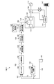
- FIG. 3 is an explanatory diagram showing a coal gasification power plant
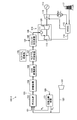
- FIG. 4 is an explanatory diagram showing another coal gasification power plant.
- this coal gasification power plant 100-1 gasifies coal 101 in a gasification furnace 102, obtains a gasification gas 103 as a product gas, and then removes dust in a dust removing device 104.
- the COS conversion device 105 converts COS into H 2 S
- the CO shift reaction device 106 causes the CO shift reaction
- the H 2 S / CO 2 recovery device 107 recovers CO 2
- the H 2 S is removed.
- reference numeral 120 is air
- 121 is an air separation device that separates air into nitrogen (N 2 ) and oxygen (O 2 )
- 122 is gasified air compressor
- 123 is gasified air
- 124 is water vapor.
- 125 respectively illustrate the H 2 S / CO 2 treatment system.
- the produced gas 108 after being processed by the H 2 S / CO 2 recovery device 107 is supplied to a combustor 111 of a gas turbine 110 which is a power generation means, where it is burned to produce a high temperature / high pressure combustion gas.
- the turbine 112 is driven by this combustion gas.
- the turbine 112 is connected to a generator 113, and the generator 113 generates electric power when the turbine 112 is driven.
- the exhaust gas 114 after driving the turbine 112 still has a temperature of 500 to 600 ° C., it is preferably sent to an HRSG (Heat Recovery Steam Generator) 115 to recover the thermal energy.
- HRSG Heat Recovery Steam Generator
- steam is generated by the thermal energy of the exhaust gas, and the steam turbine 116 is driven by the steam.
- the exhaust gas whose thermal energy has been recovered by the HRSG 115 is discharged into the atmosphere via the chimney 117 after the NOx content in the exhaust gas is removed by a denitration device (not shown).
- the gasification gas 103 gasified in the gasification furnace 102 is hydrogenated from carbon monoxide (CO) and water vapor (H 2 O) contained in the gasification gas 103 before separating CO 2.
- a so-called CO shift reactor 106 for producing (H 2 ) is required.
- useful components CO 2 and H 2 are obtained by the reaction of the following formula (1).
- the CO shift reaction device 106 in order to convert CO contained in a large amount in the gasification gas 103 into H 2 , in addition to the gas for the turbine, a gas composition suitable for synthesis of chemical products such as methanol and ammonia, for example. Of purified gas is obtained.
- a CO shift reactor 106 having this CO shift catalyst is provided between a COS converter 105 such as a coal gasification power plant 100-1 shown in FIG. 3 and an H 2 S / CO 2 recovery unit 107 (H 2 S / In addition to being installed on the upstream side of the CO 2 recovery unit 107), it is proposed to be installed on the downstream side of the H 2 S / CO 2 recovery unit 107 as in the coal gasification power plant 100-2 shown in FIG. There is also a case.
- a copper (Cu) -zinc (Zn) -based catalyst which is a general catalyst for a CO shift catalyst, is poisoned in a sulfur component (S component) atmosphere. Therefore, H 2 S / CO as shown in FIG. 2 There is a problem that it cannot be used when the CO shift reaction device 106 is installed on the rear side of the recovery device 107.
- CO shift that has excellent S resistance in the range of H 2 S concentration of 0.1 to 100 ppm, preferably 0.5 to 50 ppm, and can stabilize the catalyst performance by using a high specific surface area carrier.
- the appearance of a catalyst is desired.
- the present invention provides a CO shift catalyst, a CO shift reaction apparatus, and a gasification gas purification method that are excellent in S resistance even when the H 2 S concentration is low and can stabilize the catalyst performance. Let it be an issue.
- a first invention of the present invention for solving the above-described problem is a CO shift catalyst for reforming carbon monoxide (CO) in a gas, and is any one of molybdenum (Mo) and iron (Fe). Of active ingredient having nickel (Ni) or ruthenium (Ru) as an accessory component, and titanium (Ti), zirconium (Zr) and cerium (Ce) supporting this active component.
- the present invention is a CO shift catalyst characterized by using any one kind or two or more kinds of oxides as a support.
- the second invention is the CO shift catalyst according to the first invention, wherein the carrier contains a complex oxide containing at least two kinds of elements.
- the loading amount of the main component of the active ingredient is 0.1 to 25% by weight and the loading amount of the subcomponent is 0.01 to 1.5% by weight. It is in the CO shift catalyst characterized by being.
- a fourth invention is a CO shift reaction apparatus characterized by filling any one of the first to third CO shift catalysts in a reaction tower.
- the gasification gas after the CO shift reaction is further purified by a wet scrubber device, and then in the gasification gas Carbon dioxide and hydrogen sulfide are removed, and purification is performed by CO shift reaction that converts CO in gasified gas into CO 2 under low concentration of hydrogen sulfide using any one of the first to third CO shift catalysts.
- a gasification gas purification method is characterized in that a gas is obtained.
- a CO shift reaction can be performed even at a low H 2 S concentration.
- FIG. 1 is a schematic view of a gasification gas purification system provided with a CO shift reaction apparatus filled with a CO shift catalyst according to the present embodiment.
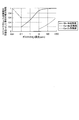
- FIG. 2 is a graph showing the relationship between catalyst activity and H 2 S concentration.
- FIG. 3 is an explanatory diagram showing a coal gasification power plant.
- FIG. 4 is an explanatory diagram showing another coal gasification power plant.
- FIG. 1 is a schematic view of a gasification gas purification system equipped with a CO shift reaction apparatus filled with a CO shift catalyst.
- the gasification gas purification system 10 includes a gasification furnace 11 that gasifies coal that is fuel F, a filter 13 that removes soot and dust in the gasification gas 12 that is a generated gas, and a filter 13.
- symbol 21 illustrates water vapor
- a CO shift catalyst according to the present invention is a CO shift catalyst for reforming carbon monoxide (CO) in a gas, and contains nickel (Mo) or iron (Fe) as a main component, and nickel. (Ni) or ruthenium (Ru) as one of the active ingredients, and any one or two of the oxides of titanium (Ti), zirconium (Zr) and cerium (Ce) carrying the active ingredients More than a seed is used as a carrier.
- a catalyst excellent in low-temperature activity can be provided, and the amount of water vapor is reduced (for example, from 350 ° C. to 250 ° C. In this case, the CO shift reaction is allowed to proceed efficiently.
- the carrier is preferably an oxide of TiO 2 , ZrO 2 , or CeO 2 .
- the carrier may contain a complex oxide in which at least two kinds or two or more kinds of elements are present.
- a complex oxide in which at least two kinds or two or more kinds of elements are present.
- the case where the composite oxide and the mixture coexist is also included.
- the composite oxide obtained can be exemplified, for example, TiO 2 -ZrO 2, TiO 2 -CeO 2, CeO 2 -ZrO 2, composite oxides and the like.
- the supported amount of molybdenum (Mo) or iron (Fe) as the main component is preferably 0.1 to 25% by weight, more preferably 5 to 22% by weight.
- the supported amount of Ni) or ruthenium (Ru) is preferably 0.01 to 10% by weight, more preferably 3 to 10% by weight, and in the case of ruthenium (Ru), more preferably 0.01 to 1.5% by weight. % Is good.
- the purified gas 22 can be obtained by performing the CO shift reaction at a low H 2 S concentration using the CO shift reaction apparatus 20 having the CO shift catalyst 19.
- Mo—Ni-based catalyst of the present invention contains Ni element as an accessory component, molybdenum sulfide can be stabilized even at a low H 2 S concentration, so that the H 2 S partial pressure is small. However, it is presumed that the equilibrium composition is restrained from leaning to the left in the formula (2) and the catalytic activity can be maintained.
- the CO shift reaction device 20 when the CO shift reaction device 20 is installed on the rear stage side of the gas purification device 15 which is an H 2 S / CO 2 recovery device, the H 2 S concentration becomes 0.1 to 100 ppm, and the above equation (2) Since the shift of the equilibrium to the left side is suppressed by the secondary component Ni catalyst, the catalytic activity is maintained well, the S resistance is excellent, and the catalyst performance is stabilized by using a high specific surface area carrier. Can be achieved.
- FIG. 2 is a graph showing the relationship between catalyst activity and H 2 S concentration.
- the vertical axis represents the relative performance when the performance of the S—free Cu—Zn-based catalyst is 1
- the horizontal axis represents the H 2 S concentration (ppm) in the gas.
- the Mo-Ni-based catalyst according to the present invention the concentration of H 2 S are shown catalytic activity even when extremely low as about 0.1 ppm, the concentration of H 2 S is 10 ⁇ 1000 ppm, relative values It shows a high activity of 0.9 or higher.
- the Co—Mo catalyst shows a low activity of a relative value of 0.3 or less at an H 2 S concentration of 10 to 100 ppm.
- the Mo—Ni-based catalyst according to the present invention exhibits catalytic activity even when the H 2 S concentration is extremely low.
- the CO shift catalyst according to the present invention when CO in the gasification gas 12 gasified in the gasification furnace 11 is converted to H 2 , the low H 2 on the rear stage side of the gas purification device 15 is reduced. Even in the case of S concentration, shift reaction is possible, and a highly efficient gas purification process can be provided.
- Catalyst 1 a powder catalyst.
- the obtained catalyst powder was fixed with a 30-ton pressure molding machine, and then crushed and sieved so that the particle size was in the range of 2 to 4 mm to obtain Catalyst 1.
- the obtained catalyst powder was fixed with a 30-ton pressure molding machine and then crushed and sieved so that the particle size was in the range of 2 to 4 mm to obtain catalyst 6.
- comparative catalyst 1 [impregnation (IMP) method] Cobalt nitrate hexahydrate (CN) and ammonium molybdate tetrahydrate (MA) in which 100 g of ⁇ -Al 2 O 3 (A-11) manufactured by Sumitomo Chemical was placed in a magnetic dish and dissolved in 150 ml of water Was added so as to carry 4% by weight of CoO and 13% by weight of MoO 3 with respect to the total amount of powder finally obtained, and then impregnated by evaporation to dryness on a magnetic dish. The obtained powder was completely dried in a drier and then calcined at 500 ° C.
- IMP impregnation
- the ratio of aluminum nitrate, zinc nitrate, and copper nitrate may be set to 50:15:35 weight% in the form of a metal oxide, and sodium carbonate is 2 of the addition molar amount of aluminum nitrate, zinc nitrate, and copper nitrate. Doubled. Furthermore, the raw material was added so that the catalyst amount prepared by the above blending would be 100 g in theoretical conversion. In the preparation method, the solution B was uniformly added dropwise to the solution A over 30 minutes while stirring to obtain a precipitation product solution D. Next, the solution C was dripped uniformly over the said precipitation product liquid D over 30 minutes, and the precipitation product liquid F containing aluminum, zinc, and copper was obtained.
- the precipitation product solution F was aged by stirring for 2 hours, and then sufficiently washed so that the filtrate of the precipitation product solution F and Na ions and NO ions were not detected. Further, the catalyst was dried at 100 ° C. for 24 hours, and then calcined at 300 ° C. for 3 hours to obtain a comparative catalyst powder. The obtained comparative catalyst powder was fixed with a 30-ton pressure molding machine, and then crushed so as to have a particle size in the range of 2 to 4 mm, followed by sieving to obtain comparative catalyst 2 (ratio 2). .
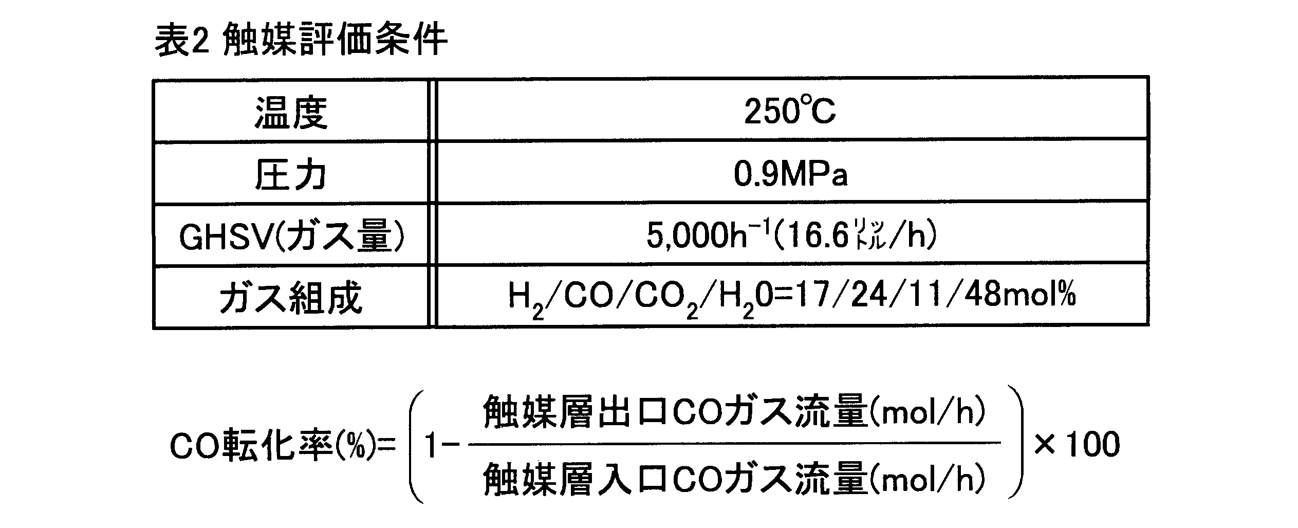
- the evaluation of the catalyst was performed as follows. In the evaluation test, 3.3 cc of the catalyst was filled in a tubular reaction tube having an inner diameter of 14 mm, and the catalytic activity was evaluated by a flow type microreactor apparatus. The comparison of the catalyst activity was arranged by the parameter defined as the CO conversion rate shown in Table 2 below, based on the gas flow rate change at the catalyst layer inlet and outlet.
- Table 1 shows a list of the composition of the catalyst and the test results.
- the catalyst according to this test example had good activity even at a low H 2 S concentration (20 ppm), and all the catalysts had good CO conversion.
- the Mo—Ni catalysts of Catalysts 1 to 5 had good initial activity, and the decrease in CO conversion after the 200-hour durability test was extremely small.
- the CO conversion rate was significantly reduced. Comparative catalyst 2 had little activity.
Landscapes
- Chemical & Material Sciences (AREA)
- Engineering & Computer Science (AREA)
- Combustion & Propulsion (AREA)
- Organic Chemistry (AREA)
- Chemical Kinetics & Catalysis (AREA)
- Materials Engineering (AREA)
- Oil, Petroleum & Natural Gas (AREA)
- General Chemical & Material Sciences (AREA)
- Mechanical Engineering (AREA)
- General Engineering & Computer Science (AREA)
- Health & Medical Sciences (AREA)
- General Health & Medical Sciences (AREA)
- Inorganic Chemistry (AREA)
- Life Sciences & Earth Sciences (AREA)
- Sustainable Development (AREA)
- Sustainable Energy (AREA)
- Physics & Mathematics (AREA)
- Thermal Sciences (AREA)
- Catalysts (AREA)
- Hydrogen, Water And Hydrids (AREA)
Abstract
Description
一方、石炭を付加価値の高いエネルギー媒体として、変換するためには石炭ガス化技術、ガス精製技術など高度な技術が必要とされる。
このガス化ガスを用いて発電する石炭ガス化複合発電システムが提案されている(特許文献1)。
この石炭ガス化複合発電(Integrated coal Gasification Combined Cycle:IGCC)とは、石炭を高温高圧のガス化炉で可燃性ガスに転換し、そのガス化ガスを燃料としてガスタービンと蒸気タービンとによる複合発電を行うシステムをいう。
図3に示すように、この石炭ガス化発電プラント100-1は、石炭101をガス化炉102でガス化し、生成ガスであるガス化ガス103を得た後、脱塵装置104で除塵した後、COS変換装置105でCOSをH2Sに変換した後、COシフト反応装置106でCOシフト反応を起こさせた後、H2S/CO2回収装置107でCO2を回収すると共に、ガス中のH2Sの除去をおこなっている。なお、図中、符号120は空気、121は空気を窒素(N2)と酸素(O2)とに分離する空気分離装置、122はガス化空気圧縮機、123はガス化空気、124は水蒸気、125はH2S/CO2処理系を各々図示する。
このCOシフト反応は、下記式(1)の反応により有用成分であるCO2とH2とを得るようにしている。
CO+H2O→CO2+H2…(1)
図1に示すように、ガス化ガス精製システム10は、燃料Fである石炭をガス化するガス化炉11と、生成ガスであるガス化ガス12中の煤塵を除去するフィルタ13と、フィルタ13を通過した後のガス化ガス12中のハロゲンを除去する湿式スクラバ装置14と、熱交換後のガス化ガス12中のCO2及びH2Sを吸収除去する吸収塔15Aと再生する再生塔15Bからなると共に再生塔15B側に再生過熱器16を備えたガス精製装置15と、ガス化ガス12の温度を上げる第1の熱交換器17及び第2の熱交換器18と、温度が300℃に上昇されたガス化ガス12中のCOをCO2に変換して精製ガス22とするCOシフト触媒19を備えたCOシフト反応装置20と、を具備するものである。なお、図1中、符号21は水蒸気を図示する。
ここで、得られる複合酸化物としては、例えばTiO2-ZrO2、TiO2-CeO2、CeO2-ZrO2、等の複合酸化物を例示することができる。
下記式(2)は、酸化モリブデンが硫化水素を反応して硫化モリブデンとなる反応式である。
MoOx+xH2S⇔MoSx+xH2O(x=0~3)…(2)
2)ここで、触媒活性と硫化度合い(硫化物の割合を示す)とは相関関係を有し、硫化度合いが小さければ、触媒活性も低いこととなる。
3)ルシャトリエの法則から、系内のH2S分圧が小さければ、平衡組成は上記式(2)において、左側に傾くので、硫化モリブデンの量が減少し、活性も低くなる傾向となる。
4)本発明のMo-Ni系触媒では、副成分としてNi元素を含んでいるので、低H2S濃度でも硫化モリブデンを安定させることができるので、H2S分圧が小さい場合であっても、平衡組成は式(2)において、左側に傾くことが抑制され、触媒活性も維持できると、推察される。
図2に示すように、本発明に係るMo-Ni系触媒では、H2S濃度が0.1ppm程度と極めて低い場合でも触媒活性が示され、H2S濃度が10~1000ppmでは、相対値0.9以上の高い活性を示している。
これに対して、Co-Mo系触媒では、H2S濃度10~100ppmでは、相対値0.3以下と低い活性を示している。
これにより、本発明に係るMo-Ni系触媒は、H2S濃度が極めて低い場合でも触媒活性が示されることとなることが判明した。
以下、本発明の効果を示す試験例について説明する。
1)触媒1の製法[含浸(IMP)法]
石原産業製酸化チタン(TiO2(「MC-90」商品名))を100g磁製皿に入れ、150mlの水に溶かした硝酸ニッケル・6水和物(NN)とモリブデン酸アンモニウム・4水和物(MA)を、最終的に得られる全粉末量に対してNiOが5重量%、MoO3が15重量%担持されるように添加後、磁製皿上で蒸発乾固含浸した。そして、得られた粉末を乾燥器で完全に乾燥後、500℃で3時間(昇温速度100℃/h)焼成を施すことにより粉末触媒を得た。
得られた触媒粉末を30tonの加圧成形器で粉末を固定化させた後、粒径が2~4mmの範囲となるように破砕後篩い分けして触媒1を得た。
石原産業製酸化チタン(TiO2(「MC-90」商品名))を100g、3Lの水が入ったビーカーに入れ、その中に硝酸ニッケル・6水和物を最終的に得られる全粉末量に対してNiOが5重量%となるように添加する。
ビーカー内を攪拌して硝酸ニッケルを溶解後、攪拌を継続した状態で炭酸ナトリウム2.5mol%を水2Lに溶解させた溶液を滴下し、沈殿させる。
次に、モリブデン酸アンモニウム・4水和物を最終的に得られる全粉末量に対してMoO3が15重量%担持されるように添加し、攪拌溶解する。
そして、攪拌を継続した状態で1Nの硝酸水溶液を滴下し、沈殿させる。
最後に、遠心分離機で洗浄ろ過、乾燥後、500℃で3時間(昇温速度100℃/h)焼成を施すことにより粉末触媒を得た。
得られた触媒粉末を30tonの加圧成形器で粉末を固定化させた後、粒径が2~4mmの範囲となるように破砕後篩い分けして触媒2を得た。
第一希元素製10重量%ZrO2/TiO2を100g磁製皿に入れ、150mlの水に溶かした硝酸ニッケル・6水和物とモリブデン酸アンモニウム・4水和物を、最終的に得られる全粉末量に対してNiOが5重量%、MoO3が15重量%担持されるように添加後、磁製皿上で蒸発乾固含浸した。そして、得られた粉末を乾燥器で完全に乾燥後、500℃で3時間(昇温速度100℃/h)焼成を施すことにより粉末触媒を得た。
得られた触媒粉末を30tonの加圧成形器で粉末を固定化させた後、粒径が2~4mmの範囲となるように破砕後篩い分けして触媒3を得た。
第一希元素製CeO2を100g磁製皿に入れ、150mlの水に溶かした硝酸ニッケル・6水和物とモリブデン酸アンモニウム・4水和物を、最終的に得られる全粉末量に対してNiOが6重量%、MoO3が20重量%担持されるように添加後、磁製皿上で蒸発乾固含浸した。そして、得られた粉末を乾燥器で完全に乾燥後、500℃で3時間(昇温速度100℃/h)焼成を施すことにより粉末触媒を得た。
得られた触媒粉末を30tonの加圧成形器で粉末を固定化させた後、粒径が2~4mmの範囲となるように破砕後篩い分けして触媒4を得た。
第一希元素製80重量%CeO2/ZrO2を100g磁製皿に入れ、150mlの水に溶かした硝酸ニッケル・6水和物とモリブデン酸アンモニウム・4水和物を、最終的に得られる全粉末量に対してNiOが6重量%、MoO3が14重量%担持されるように添加後、磁製皿上で蒸発乾固含浸した。そして、得られた粉末を乾燥器で完全に乾燥後、500℃で3時間(昇温速度100℃/h)焼成を施すことにより粉末触媒を得た。得られた触媒粉末を30tonの加圧成形器で粉末を固定化させた後、粒径が2~4mmの範囲となるように破砕後篩い分けして触媒5を得た。
石原産業製酸化チタン(TiO2(「MC-90」商品名))を100g磁製皿に入れ、100mlの水に溶かした硝酸ルテニウム(RN)水溶液と硝酸鉄(II)・6水和物(FN)を、最終的に得られる全粉末量に対してRuが1重量%、FeOが17重量%担持されるように添加後、磁製皿上で蒸発乾固含浸した。そして、得られた粉末を乾燥器で完全に乾燥後、500℃で3時間(昇温速度100℃/h)焼成を施すことにより粉末触媒を得た。得られた触媒粉末を30tonの加圧成形器で粉末を固定化させた後、粒径が2~4mmの範囲となるように破砕後篩い分けして触媒6を得た。
第一希元素製10重量%CeO2/TiO2を100g磁製皿に入れ、100mlの水に溶かした硝酸ニッケル・6水和物(NN)と硝酸鉄(III)・6水和物(FN)を、最終的に得られる全粉末量に対してNiが9重量%、Fe2O3が17重量%担持されるように添加後、磁製皿上で蒸発乾固含浸した。そして、得られた粉末を乾燥器で完全に乾燥後、500℃で3時間(昇温速度100℃/h)焼成を施すことにより粉末触媒を得た。得られた触媒粉末を30tonの加圧成形器で粉末を固定化させた後、粒径が2~4mmの範囲となるように破砕後篩い分けして触媒7を得た。
住友化学製γ-Al2O3(A-11)を100g磁製皿に入れ、150mlの水に溶かした硝酸コバルト・6水和物(CN)とモリブデン酸アンモニウム・4水和物(MA)を、最終的に得られる全粉末量に対してCoOが4重量%、MoO3が13重量%担持されるように添加後、磁製皿上で蒸発乾固含浸した。そして、得られた粉末を乾燥器で完全に乾燥後、500℃で3時間(昇温速度100℃/h)焼成を施すことにより粉末触媒を得た。
得られた触媒粉末を30tonの加圧成形器で粉末を固定化させた後、粒径が2~4mmの範囲となるように破砕後篩い分けして比較触媒1(比1)を得た。
炭酸ナトリウムを水2Lに溶解させ、60℃に保温してこのアルカリ溶液を溶液Aとした。次に硝酸アルミニウム及び硝酸亜鉛を水400mlに溶解させ、60℃に保温した酸性溶液を溶液Bとした。また、硝酸銅(CUN)を水400mlに溶かして60℃に保温した酸性溶液を溶液Cとした。なお、硝酸アルミニウム、硝酸亜鉛及び硝酸銅の比率は金属酸化物の形態で50:15:35重量%となるように配合し、炭酸ナトリウムは硝酸アルミニウム、硝酸亜鉛及び硝酸銅の添加モル量の2倍量とした。さらに上記配合で調製する触媒量は理論換算で100gとなるように原料を添加した。
調製方法は、攪拌しながら溶液Aに溶液Bを30分にわたり均一に滴下し、沈殿生成液Dを得た。次に、溶液Cを前記の沈殿生成液Dに30分にわたり均一に滴下し、アルミニウム、亜鉛及び銅を含有した沈殿生成液Fを得た。
沈殿生成液Fを、2時間そのまま攪拌することにより熟成を行い、次に沈殿生成液Fのろ液及びNaイオン、NOイオンが検出されないように、十分に洗浄した。さらに、100℃で24時間乾燥し、その後、300℃で3時間焼成することにより比較触媒粉末を得た。得られた比較触媒粉末を30tonの加圧成形器で粉末を固定化させた後、粒径が2~4mmの範囲となるように破砕後篩い分けして比較触媒2(比2)を得た。
評価試験は、内径14mmの管型反応管に触媒を3.3cc充填し、流通式マイクロリアクタ装置により触媒活性を評価した。触媒活性の比較は、触媒層入口、出口のガス流量変化で、下記表2に示すCO転化率と定義するパラメータで整理した。
ガス組成は、H2/CO/CO2/H2O=17/24/11/48モル%、H2S=20ppm、S/CO=2.0とし、0.9MPa、温度250℃の条件で試験した。評価条件については表2に示す。CO転化率は表2の下段の式による。

これに対し、比較例にかかる比較触媒1は、CO転化率が大幅に低下した。比較触媒2は殆ど活性が無かった。
11 ガス化炉
12 ガス化ガス
13 フィルタ
14 湿式スクラバ装置
15A 吸収塔
15B 再生塔
15 ガス精製装置
16 再生過熱器
17 第1の熱交換器
18 第2の熱交換器
19 COシフト触媒
20 COシフト反応装置
22 精製ガス
Claims (5)
- ガス中の一酸化炭素(CO)を改質するCOシフト触媒であって、
モリブデン(Mo)又は鉄(Fe)のいずれか一種を主成分とすると共に、
ニッケル(Ni)又はルテニウム(Ru)のいずれか一種を副成分とする活性成分と、
この活性成分を担持するチタン(Ti)、ジルコニウム(Zr)及びセリウム(Ce)のいずれか一種又は二種以上の酸化物を担体とすることを特徴とするCOシフト触媒。 - 請求項1において、
前記担体が、少なくとも二種の元素が存在する複合酸化物を含むものであることを特徴とするCOシフト触媒。 - 請求項1又は2において、
活性成分の主成分の担持量が0.1~25重量%であると共に、副成分の担持量が0.01~1.5重量%であることを特徴とするCOシフト触媒。 - 請求項1乃至3のいずれか一つのCOシフト触媒を反応塔内に充填してなることを特徴とするCOシフト反応装置。
- ガス化炉で得られたガス化ガス中の煤塵をフィルタで除去した後、
湿式スクラバ装置によりさらにCOシフト反応後のガス化ガスを浄化し、
次いで、ガス化ガス中の二酸化炭素及び硫化水素を除去し、
請求項1乃至3のいずれか一つのCOシフト触媒を用いて、
低濃度の硫化水素下において、ガス化ガス中のCOをCO2に変換するCOシフト反応させ精製ガスを得ることを特徴とするガス化ガスの精製方法。
Priority Applications (4)
| Application Number | Priority Date | Filing Date | Title |
|---|---|---|---|
| US13/519,683 US8828339B2 (en) | 2010-02-24 | 2011-02-24 | CO shift catalyst, CO shift reactor, and method for purifying gasified gas |
| JP2012501852A JP5550715B2 (ja) | 2010-02-24 | 2011-02-24 | Coシフト触媒、coシフト反応装置及びガス化ガスの精製方法 |
| CN201180004717.8A CN102630186B (zh) | 2010-02-24 | 2011-02-24 | Co变换催化剂、co变换反应装置及煤气化气体的精制方法 |
| AU2011221123A AU2011221123B2 (en) | 2010-02-24 | 2011-02-24 | CO shift catalyst , CO shift reaction apparatus, and method for purification of gasified gas |
Applications Claiming Priority (2)
| Application Number | Priority Date | Filing Date | Title |
|---|---|---|---|
| JP2010-039412 | 2010-02-24 | ||
| JP2010039412 | 2010-02-24 |
Publications (1)
| Publication Number | Publication Date |
|---|---|
| WO2011105501A1 true WO2011105501A1 (ja) | 2011-09-01 |
Family
ID=44506903
Family Applications (1)
| Application Number | Title | Priority Date | Filing Date |
|---|---|---|---|
| PCT/JP2011/054167 Ceased WO2011105501A1 (ja) | 2010-02-24 | 2011-02-24 | Coシフト触媒、coシフト反応装置及びガス化ガスの精製方法 |
Country Status (5)
| Country | Link |
|---|---|
| US (1) | US8828339B2 (ja) |
| JP (1) | JP5550715B2 (ja) |
| CN (1) | CN102630186B (ja) |
| AU (1) | AU2011221123B2 (ja) |
| WO (1) | WO2011105501A1 (ja) |
Cited By (14)
| Publication number | Priority date | Publication date | Assignee | Title |
|---|---|---|---|---|
| JP2012066237A (ja) * | 2010-08-27 | 2012-04-05 | Hitachi Ltd | シフト触媒、ガス精製方法及び設備 |
| WO2013094512A1 (ja) * | 2011-12-22 | 2013-06-27 | 三菱重工業株式会社 | Coシフト反応装置およびcoシフト反応方法 |
| JP2013209485A (ja) * | 2012-03-30 | 2013-10-10 | Hitachi Ltd | ガス精製方法、石炭ガス化プラント及びシフト触媒 |
| JP2014009166A (ja) * | 2012-06-27 | 2014-01-20 | Osaka Gas Co Ltd | 高カロリーガスの製造方法及び高カロリーガスの製造装置 |
| EP2568130A3 (en) * | 2011-09-12 | 2014-04-02 | Hitachi Ltd. | Heat recovery system of the boiler with CO2 capture system |
| WO2014103075A1 (ja) * | 2012-12-28 | 2014-07-03 | 三菱重工業株式会社 | Coシフト触媒、coシフト反応装置及びガス化ガスの精製方法 |
| WO2014103076A1 (ja) * | 2012-12-28 | 2014-07-03 | 三菱重工業株式会社 | Coシフト触媒、coシフト反応装置及びガス化ガスの精製方法 |
| WO2014103074A1 (ja) * | 2012-12-28 | 2014-07-03 | 三菱重工業株式会社 | Coシフト触媒、coシフト反応装置及びガス化ガスの精製方法 |
| WO2014129440A1 (ja) * | 2013-02-21 | 2014-08-28 | 三菱重工業株式会社 | Coシフト反応装置及びcoシフト変換方法 |
| WO2014132367A1 (ja) * | 2013-02-27 | 2014-09-04 | 三菱重工業株式会社 | Coシフト触媒、coシフト反応装置及びガス化ガスの精製方法 |
| US9238208B2 (en) | 2012-02-27 | 2016-01-19 | Mitsubishi Heavy Industries, Ltd. | CO shift reaction apparatus and gasification gas refining system |
| JP2019214023A (ja) * | 2018-06-13 | 2019-12-19 | 日本製鉄株式会社 | 水性ガスシフト反応触媒の製造方法、水性ガスシフト反応触媒、及び水素の製造方法 |
| US10774278B2 (en) | 2013-02-27 | 2020-09-15 | Mitsubishi Heavy Industries Engineering, Ltd. | CO shift catalyst, CO shift reaction apparatus, and method for purifying gasified gas |
| CN119897113A (zh) * | 2023-10-27 | 2025-04-29 | 中国石油化工股份有限公司 | 一种一氧化碳变换催化剂及其制备方法和应用 |
Families Citing this family (4)
| Publication number | Priority date | Publication date | Assignee | Title |
|---|---|---|---|---|
| CN107118810A (zh) * | 2017-05-05 | 2017-09-01 | 北京清创晋华科技有限公司 | 一种将出洗涤塔合成气升温除液态水的方法 |
| JP6934437B2 (ja) * | 2018-03-14 | 2021-09-15 | 三菱重工エンジニアリング株式会社 | ガス精製装置 |
| CN114177913A (zh) * | 2021-12-03 | 2022-03-15 | 浙江皇马科技股份有限公司 | 一种用于合成聚醚胺的负载型催化剂、制备方法及应用 |
| CN117943082A (zh) * | 2023-12-04 | 2024-04-30 | 山东大学 | 一种高温逆水煤气变换反应MoOx/Mo2N催化剂及其制备方法 |
Citations (5)
| Publication number | Priority date | Publication date | Assignee | Title |
|---|---|---|---|---|
| JPS5648553B2 (ja) * | 1978-07-26 | 1981-11-16 | ||
| JP2003073107A (ja) * | 2001-06-19 | 2003-03-12 | Matsushita Electric Ind Co Ltd | 水素精製装置および燃料電池発電システム |
| JP2005521617A (ja) * | 2002-03-28 | 2005-07-21 | ユーティーシー フューエル セルズ,エルエルシー | セリア基の混合金属酸化物構造、その作成方法および使用 |
| JP2006181473A (ja) * | 2004-12-27 | 2006-07-13 | Toda Kogyo Corp | 水性ガスシフト反応用の触媒及びその製造方法 |
| JP2009090184A (ja) * | 2007-10-05 | 2009-04-30 | Toda Kogyo Corp | 水性ガスシフト反応用の触媒及びその製造方法 |
Family Cites Families (12)
| Publication number | Priority date | Publication date | Assignee | Title |
|---|---|---|---|---|
| US4153580A (en) | 1977-12-09 | 1979-05-08 | United Catalysts Inc. | CO conversion catalyst |
| US4233180A (en) | 1978-11-13 | 1980-11-11 | United Catalysts Inc. | Process for the conversion of carbon monoxide |
| JPS5648553A (en) * | 1979-09-28 | 1981-05-01 | Sumitomo Chem Co Ltd | Simple analyzing method for alcohol in liquid fuel |
| JPS5829140B2 (ja) * | 1980-03-06 | 1983-06-21 | 工業技術院長 | 高カロリ−ガス製造用触媒 |
| FR2575453B1 (fr) * | 1984-12-28 | 1990-03-02 | Pro Catalyse | Procede de conversion du monoxyde de carbone par la vapeur d'eau a l'aide d'un catalyseur thioresistant |
| CN1066415C (zh) * | 1997-12-07 | 2001-05-30 | 中国石化齐鲁石油化工公司 | 一种一氧化碳耐硫变换催化剂及制备方法 |
| CN1457320A (zh) * | 2001-01-26 | 2003-11-19 | 松下电器产业株式会社 | 氢气提纯装置和燃料电池发电系统 |
| JP4066611B2 (ja) | 2001-03-30 | 2008-03-26 | 松下電工株式会社 | 放電灯点灯装置 |
| JP4015391B2 (ja) | 2001-09-07 | 2007-11-28 | 三菱重工業株式会社 | Coシフト触媒及びその製造方法 |
| WO2004058633A2 (en) * | 2002-12-20 | 2004-07-15 | Honda Giken Kogyo Kabushiki Kaisha | Platinum-free ruthenium-cobalt catalyst formulations for hydrogen generation |
| JP4436068B2 (ja) | 2003-04-30 | 2010-03-24 | 株式会社クリーンコールパワー研究所 | 石炭ガス化プラント、および石炭ガス化方法、および石炭ガス化発電プラント、並びに石炭ガス化プラントの増設設備 |
| JP5648553B2 (ja) | 2011-03-18 | 2015-01-07 | 富士通株式会社 | 引用回数管理プログラム、引用回数管理装置および引用回数管理方法 |
-
2011
- 2011-02-24 AU AU2011221123A patent/AU2011221123B2/en not_active Ceased
- 2011-02-24 WO PCT/JP2011/054167 patent/WO2011105501A1/ja not_active Ceased
- 2011-02-24 JP JP2012501852A patent/JP5550715B2/ja active Active
- 2011-02-24 US US13/519,683 patent/US8828339B2/en active Active
- 2011-02-24 CN CN201180004717.8A patent/CN102630186B/zh not_active Expired - Fee Related
Patent Citations (5)
| Publication number | Priority date | Publication date | Assignee | Title |
|---|---|---|---|---|
| JPS5648553B2 (ja) * | 1978-07-26 | 1981-11-16 | ||
| JP2003073107A (ja) * | 2001-06-19 | 2003-03-12 | Matsushita Electric Ind Co Ltd | 水素精製装置および燃料電池発電システム |
| JP2005521617A (ja) * | 2002-03-28 | 2005-07-21 | ユーティーシー フューエル セルズ,エルエルシー | セリア基の混合金属酸化物構造、その作成方法および使用 |
| JP2006181473A (ja) * | 2004-12-27 | 2006-07-13 | Toda Kogyo Corp | 水性ガスシフト反応用の触媒及びその製造方法 |
| JP2009090184A (ja) * | 2007-10-05 | 2009-04-30 | Toda Kogyo Corp | 水性ガスシフト反応用の触媒及びその製造方法 |
Cited By (32)
| Publication number | Priority date | Publication date | Assignee | Title |
|---|---|---|---|---|
| JP2012066237A (ja) * | 2010-08-27 | 2012-04-05 | Hitachi Ltd | シフト触媒、ガス精製方法及び設備 |
| EP2568130A3 (en) * | 2011-09-12 | 2014-04-02 | Hitachi Ltd. | Heat recovery system of the boiler with CO2 capture system |
| US20140346403A1 (en) * | 2011-12-22 | 2014-11-27 | Mitsubishi Heavy Industries, Ltd. | Carbon monoxide shift reaction apparatus and carbon monoxide shift reaction method |
| WO2013094512A1 (ja) * | 2011-12-22 | 2013-06-27 | 三菱重工業株式会社 | Coシフト反応装置およびcoシフト反応方法 |
| AU2012354919B2 (en) * | 2011-12-22 | 2016-01-21 | Mitsubishi Heavy Industries Engineering, Ltd. | CO shift reaction apparatus and CO shift reaction method |
| US9238208B2 (en) | 2012-02-27 | 2016-01-19 | Mitsubishi Heavy Industries, Ltd. | CO shift reaction apparatus and gasification gas refining system |
| JP2013209485A (ja) * | 2012-03-30 | 2013-10-10 | Hitachi Ltd | ガス精製方法、石炭ガス化プラント及びシフト触媒 |
| TWI491726B (zh) * | 2012-03-30 | 2015-07-11 | Mitsubishi Hitachi Power Sys | 氣體精製方法、煤氣化設備及轉移觸媒 |
| JP2014009166A (ja) * | 2012-06-27 | 2014-01-20 | Osaka Gas Co Ltd | 高カロリーガスの製造方法及び高カロリーガスの製造装置 |
| WO2014103075A1 (ja) * | 2012-12-28 | 2014-07-03 | 三菱重工業株式会社 | Coシフト触媒、coシフト反応装置及びガス化ガスの精製方法 |
| JPWO2014103075A1 (ja) * | 2012-12-28 | 2017-01-12 | 三菱重工業株式会社 | Coシフト触媒、coシフト反応装置及びガス化ガスの精製方法 |
| JPWO2014103074A1 (ja) * | 2012-12-28 | 2017-01-12 | 三菱重工業株式会社 | Coシフト触媒、coシフト反応装置及びガス化ガスの精製方法 |
| WO2014103074A1 (ja) * | 2012-12-28 | 2014-07-03 | 三菱重工業株式会社 | Coシフト触媒、coシフト反応装置及びガス化ガスの精製方法 |
| US20150299592A1 (en) * | 2012-12-28 | 2015-10-22 | Mitsubishi Heavy Industries, Ltd. | Co shift catalyst, co shift reactor, and method for purifying gasification gas |
| WO2014103076A1 (ja) * | 2012-12-28 | 2014-07-03 | 三菱重工業株式会社 | Coシフト触媒、coシフト反応装置及びガス化ガスの精製方法 |
| AU2012397689C1 (en) * | 2012-12-28 | 2016-09-29 | Mitsubishi Heavy Industries Engineering, Ltd. | CO shift catalyst, CO shift reactor, and method for purifying gasification gas |
| JP6025870B2 (ja) * | 2012-12-28 | 2016-11-16 | 三菱重工業株式会社 | Coシフト触媒、coシフト反応装置及びガス化ガスの精製方法 |
| AU2012397690B2 (en) * | 2012-12-28 | 2016-04-21 | Mitsubishi Heavy Industries Engineering, Ltd. | CO shift catalyst, CO shift reactor, and method for purifying gasification gas |
| AU2012397688B2 (en) * | 2012-12-28 | 2016-05-26 | Mitsubishi Heavy Industries Engineering, Ltd. | CO shift catalyst, CO shift reactor, and method for purifying gasification gas |
| AU2012397689B2 (en) * | 2012-12-28 | 2016-06-23 | Mitsubishi Heavy Industries Engineering, Ltd. | CO shift catalyst, CO shift reactor, and method for purifying gasification gas |
| WO2014129440A1 (ja) * | 2013-02-21 | 2014-08-28 | 三菱重工業株式会社 | Coシフト反応装置及びcoシフト変換方法 |
| JP2014162803A (ja) * | 2013-02-21 | 2014-09-08 | Mitsubishi Heavy Ind Ltd | Coシフト反応装置及びcoシフト変換方法 |
| US10000378B2 (en) | 2013-02-21 | 2018-06-19 | Mitsubishi Heavy Industries, Ltd. | Carbon monoxide shift reaction apparatus and carbon monoxide shift conversion method |
| JP6005251B2 (ja) * | 2013-02-27 | 2016-10-12 | 三菱重工業株式会社 | Coシフト触媒の製造方法及びガス化ガスの精製方法 |
| US20160032202A1 (en) * | 2013-02-27 | 2016-02-04 | Mitsubishi Heavy Industries, Ltd. | Co shift catalyst, co shift reaction apparatus, and method for purifying gasified gas |
| AU2013380071B2 (en) * | 2013-02-27 | 2016-12-15 | Mitsubishi Heavy Industries Engineering, Ltd. | CO shift catalyst, CO shift reaction apparatus and method for purifying gasified gas |
| WO2014132367A1 (ja) * | 2013-02-27 | 2014-09-04 | 三菱重工業株式会社 | Coシフト触媒、coシフト反応装置及びガス化ガスの精製方法 |
| US10774278B2 (en) | 2013-02-27 | 2020-09-15 | Mitsubishi Heavy Industries Engineering, Ltd. | CO shift catalyst, CO shift reaction apparatus, and method for purifying gasified gas |
| EP2962754B1 (en) * | 2013-02-27 | 2021-04-07 | Mitsubishi Heavy Industries Engineering, Ltd. | Method of producing co shift catalyst |
| JP2019214023A (ja) * | 2018-06-13 | 2019-12-19 | 日本製鉄株式会社 | 水性ガスシフト反応触媒の製造方法、水性ガスシフト反応触媒、及び水素の製造方法 |
| JP7020306B2 (ja) | 2018-06-13 | 2022-02-16 | 日本製鉄株式会社 | 水性ガスシフト反応触媒の製造方法、水性ガスシフト反応触媒、及び水素の製造方法 |
| CN119897113A (zh) * | 2023-10-27 | 2025-04-29 | 中国石油化工股份有限公司 | 一种一氧化碳变换催化剂及其制备方法和应用 |
Also Published As
| Publication number | Publication date |
|---|---|
| CN102630186A (zh) | 2012-08-08 |
| US20120294789A1 (en) | 2012-11-22 |
| CN102630186B (zh) | 2015-09-09 |
| JP5550715B2 (ja) | 2014-07-16 |
| AU2011221123B2 (en) | 2014-05-15 |
| AU2011221123A1 (en) | 2012-07-19 |
| US8828339B2 (en) | 2014-09-09 |
| JPWO2011105501A1 (ja) | 2013-06-20 |
Similar Documents
| Publication | Publication Date | Title |
|---|---|---|
| JP5550715B2 (ja) | Coシフト触媒、coシフト反応装置及びガス化ガスの精製方法 | |
| JP6005251B2 (ja) | Coシフト触媒の製造方法及びガス化ガスの精製方法 | |
| JP5404774B2 (ja) | Coシフト触媒、coシフト反応装置及びガス化ガスの精製方法 | |
| JP5595385B2 (ja) | Coシフト触媒及びその製造方法、並びにcoシフト触媒を用いたcoシフト反応装置 | |
| CN104507572B (zh) | Co转化催化剂、co转化反应装置及气化气的精制方法 | |
| JP6025870B2 (ja) | Coシフト触媒、coシフト反応装置及びガス化ガスの精製方法 | |
| JP5968465B2 (ja) | Coシフト触媒、coシフト反応装置及びガス化ガスの精製方法 | |
| US10774278B2 (en) | CO shift catalyst, CO shift reaction apparatus, and method for purifying gasified gas |
Legal Events
| Date | Code | Title | Description |
|---|---|---|---|
| WWE | Wipo information: entry into national phase |
Ref document number: 201180004717.8 Country of ref document: CN |
|
| 121 | Ep: the epo has been informed by wipo that ep was designated in this application |
Ref document number: 11747461 Country of ref document: EP Kind code of ref document: A1 |
|
| WWE | Wipo information: entry into national phase |
Ref document number: 2012501852 Country of ref document: JP |
|
| WWE | Wipo information: entry into national phase |
Ref document number: 2011221123 Country of ref document: AU |
|
| WWE | Wipo information: entry into national phase |
Ref document number: 13519683 Country of ref document: US |
|
| ENP | Entry into the national phase |
Ref document number: 2011221123 Country of ref document: AU Date of ref document: 20110224 Kind code of ref document: A |
|
| NENP | Non-entry into the national phase |
Ref country code: DE |
|
| 122 | Ep: pct application non-entry in european phase |
Ref document number: 11747461 Country of ref document: EP Kind code of ref document: A1 |