WO2014103074A1 - Coシフト触媒、coシフト反応装置及びガス化ガスの精製方法 - Google Patents
Coシフト触媒、coシフト反応装置及びガス化ガスの精製方法 Download PDFInfo
- Publication number
- WO2014103074A1 WO2014103074A1 PCT/JP2012/084230 JP2012084230W WO2014103074A1 WO 2014103074 A1 WO2014103074 A1 WO 2014103074A1 JP 2012084230 W JP2012084230 W JP 2012084230W WO 2014103074 A1 WO2014103074 A1 WO 2014103074A1
- Authority
- WO
- WIPO (PCT)
- Prior art keywords
- gas
- catalyst
- shift
- component
- gasification
- Prior art date
Links
- 239000003054 catalyst Substances 0.000 title claims abstract description 83
- 238000002309 gasification Methods 0.000 title claims description 71
- 238000000034 method Methods 0.000 title claims description 5
- UGFAIRIUMAVXCW-UHFFFAOYSA-N Carbon monoxide Chemical class [O+]#[C-] UGFAIRIUMAVXCW-UHFFFAOYSA-N 0.000 claims abstract description 162
- 229910002091 carbon monoxide Inorganic materials 0.000 claims abstract description 162
- 239000011575 calcium Substances 0.000 claims abstract description 17
- PXHVJJICTQNCMI-UHFFFAOYSA-N Nickel Chemical compound [Ni] PXHVJJICTQNCMI-UHFFFAOYSA-N 0.000 claims abstract description 15
- 239000011777 magnesium Substances 0.000 claims abstract description 14
- 239000011734 sodium Substances 0.000 claims abstract description 14
- 229910052698 phosphorus Inorganic materials 0.000 claims abstract description 13
- OAICVXFJPJFONN-UHFFFAOYSA-N Phosphorus Chemical compound [P] OAICVXFJPJFONN-UHFFFAOYSA-N 0.000 claims abstract description 12
- 239000011574 phosphorus Substances 0.000 claims abstract description 12
- 229910052700 potassium Inorganic materials 0.000 claims abstract description 8
- 239000010936 titanium Substances 0.000 claims abstract description 8
- DGAQECJNVWCQMB-PUAWFVPOSA-M Ilexoside XXIX Chemical compound C[C@@H]1CC[C@@]2(CC[C@@]3(C(=CC[C@H]4[C@]3(CC[C@@H]5[C@@]4(CC[C@@H](C5(C)C)OS(=O)(=O)[O-])C)C)[C@@H]2[C@]1(C)O)C)C(=O)O[C@H]6[C@@H]([C@H]([C@@H]([C@H](O6)CO)O)O)O.[Na+] DGAQECJNVWCQMB-PUAWFVPOSA-M 0.000 claims abstract description 7
- FYYHWMGAXLPEAU-UHFFFAOYSA-N Magnesium Chemical compound [Mg] FYYHWMGAXLPEAU-UHFFFAOYSA-N 0.000 claims abstract description 7
- ZLMJMSJWJFRBEC-UHFFFAOYSA-N Potassium Chemical compound [K] ZLMJMSJWJFRBEC-UHFFFAOYSA-N 0.000 claims abstract description 7
- 229910052791 calcium Inorganic materials 0.000 claims abstract description 7
- 229910052749 magnesium Inorganic materials 0.000 claims abstract description 7
- 239000011591 potassium Substances 0.000 claims abstract description 7
- 229910052708 sodium Inorganic materials 0.000 claims abstract description 7
- OYPRJOBELJOOCE-UHFFFAOYSA-N Calcium Chemical compound [Ca] OYPRJOBELJOOCE-UHFFFAOYSA-N 0.000 claims abstract description 6
- XEEYBQQBJWHFJM-UHFFFAOYSA-N Iron Chemical compound [Fe] XEEYBQQBJWHFJM-UHFFFAOYSA-N 0.000 claims abstract description 5
- ZOKXTWBITQBERF-UHFFFAOYSA-N Molybdenum Chemical compound [Mo] ZOKXTWBITQBERF-UHFFFAOYSA-N 0.000 claims abstract description 5
- KJTLSVCANCCWHF-UHFFFAOYSA-N Ruthenium Chemical compound [Ru] KJTLSVCANCCWHF-UHFFFAOYSA-N 0.000 claims abstract description 5
- 229910052750 molybdenum Inorganic materials 0.000 claims abstract description 5
- 239000011733 molybdenum Substances 0.000 claims abstract description 5
- 229910052759 nickel Inorganic materials 0.000 claims abstract description 5
- 229910052707 ruthenium Inorganic materials 0.000 claims abstract description 5
- 229910052684 Cerium Inorganic materials 0.000 claims abstract description 4
- RTAQQCXQSZGOHL-UHFFFAOYSA-N Titanium Chemical compound [Ti] RTAQQCXQSZGOHL-UHFFFAOYSA-N 0.000 claims abstract description 4
- GWXLDORMOJMVQZ-UHFFFAOYSA-N cerium Chemical compound [Ce] GWXLDORMOJMVQZ-UHFFFAOYSA-N 0.000 claims abstract description 4
- VSZWPYCFIRKVQL-UHFFFAOYSA-N selanylidenegallium;selenium Chemical compound [Se].[Se]=[Ga].[Se]=[Ga] VSZWPYCFIRKVQL-UHFFFAOYSA-N 0.000 claims abstract description 4
- 229910052719 titanium Inorganic materials 0.000 claims abstract description 4
- 239000007789 gas Substances 0.000 claims description 95
- 238000006243 chemical reaction Methods 0.000 claims description 64
- CURLTUGMZLYLDI-UHFFFAOYSA-N Carbon dioxide Chemical compound O=C=O CURLTUGMZLYLDI-UHFFFAOYSA-N 0.000 claims description 10
- 239000004480 active ingredient Substances 0.000 claims description 8
- 239000000428 dust Substances 0.000 claims description 6
- 239000001569 carbon dioxide Substances 0.000 claims description 5
- 229910002092 carbon dioxide Inorganic materials 0.000 claims description 5
- 238000002407 reforming Methods 0.000 claims description 3
- RWSOTUBLDIXVET-UHFFFAOYSA-N Dihydrogen sulfide Chemical compound S RWSOTUBLDIXVET-UHFFFAOYSA-N 0.000 claims description 2
- 229910000037 hydrogen sulfide Inorganic materials 0.000 claims description 2
- XLYOFNOQVPJJNP-UHFFFAOYSA-N water Chemical compound O XLYOFNOQVPJJNP-UHFFFAOYSA-N 0.000 description 24
- 239000003245 coal Substances 0.000 description 23
- 238000000746 purification Methods 0.000 description 17
- 238000004519 manufacturing process Methods 0.000 description 16
- 238000011084 recovery Methods 0.000 description 16
- 239000002253 acid Substances 0.000 description 11
- 238000010248 power generation Methods 0.000 description 10
- OKTJSMMVPCPJKN-UHFFFAOYSA-N Carbon Chemical compound [C] OKTJSMMVPCPJKN-UHFFFAOYSA-N 0.000 description 7
- 229910010413 TiO 2 Inorganic materials 0.000 description 7
- 229910052799 carbon Inorganic materials 0.000 description 7
- 239000003426 co-catalyst Substances 0.000 description 7
- 230000000694 effects Effects 0.000 description 7
- 238000001556 precipitation Methods 0.000 description 6
- 230000000052 comparative effect Effects 0.000 description 5
- 239000000446 fuel Substances 0.000 description 5
- 230000008929 regeneration Effects 0.000 description 5
- 238000011069 regeneration method Methods 0.000 description 5
- QGZKDVFQNNGYKY-UHFFFAOYSA-N Ammonia Chemical compound N QGZKDVFQNNGYKY-UHFFFAOYSA-N 0.000 description 4
- 230000006866 deterioration Effects 0.000 description 4
- 239000000843 powder Substances 0.000 description 4
- 229910018072 Al 2 O 3 Inorganic materials 0.000 description 3
- OKKJLVBELUTLKV-UHFFFAOYSA-N Methanol Chemical compound OC OKKJLVBELUTLKV-UHFFFAOYSA-N 0.000 description 3
- 229910052783 alkali metal Inorganic materials 0.000 description 3
- 150000001340 alkali metals Chemical class 0.000 description 3
- 230000008021 deposition Effects 0.000 description 3
- 238000005516 engineering process Methods 0.000 description 3
- 238000011156 evaluation Methods 0.000 description 3
- 229910052739 hydrogen Inorganic materials 0.000 description 3
- 239000000203 mixture Substances 0.000 description 3
- 238000010521 absorption reaction Methods 0.000 description 2
- 229910052784 alkaline earth metal Inorganic materials 0.000 description 2
- 150000001342 alkaline earth metals Chemical class 0.000 description 2
- 229910021529 ammonia Inorganic materials 0.000 description 2
- MWPLVEDNUUSJAV-UHFFFAOYSA-N anthracene Chemical compound C1=CC=CC2=CC3=CC=CC=C3C=C21 MWPLVEDNUUSJAV-UHFFFAOYSA-N 0.000 description 2
- QVGXLLKOCUKJST-UHFFFAOYSA-N atomic oxygen Chemical compound [O] QVGXLLKOCUKJST-UHFFFAOYSA-N 0.000 description 2
- 239000000567 combustion gas Substances 0.000 description 2
- 239000000470 constituent Substances 0.000 description 2
- 238000010586 diagram Methods 0.000 description 2
- 239000012717 electrostatic precipitator Substances 0.000 description 2
- 150000002430 hydrocarbons Chemical class 0.000 description 2
- 239000004615 ingredient Substances 0.000 description 2
- 238000011068 loading method Methods 0.000 description 2
- AOPCKOPZYFFEDA-UHFFFAOYSA-N nickel(2+);dinitrate;hexahydrate Chemical compound O.O.O.O.O.O.[Ni+2].[O-][N+]([O-])=O.[O-][N+]([O-])=O AOPCKOPZYFFEDA-UHFFFAOYSA-N 0.000 description 2
- 229910052760 oxygen Inorganic materials 0.000 description 2
- 239000001301 oxygen Substances 0.000 description 2
- 239000002245 particle Substances 0.000 description 2
- 229910052573 porcelain Inorganic materials 0.000 description 2
- 239000004071 soot Substances 0.000 description 2
- 239000000126 substance Substances 0.000 description 2
- IJGRMHOSHXDMSA-UHFFFAOYSA-N Atomic nitrogen Chemical compound N#N IJGRMHOSHXDMSA-UHFFFAOYSA-N 0.000 description 1
- 229910021193 La 2 O 3 Inorganic materials 0.000 description 1
- ISWSIDIOOBJBQZ-UHFFFAOYSA-N Phenol Chemical compound OC1=CC=CC=C1 ISWSIDIOOBJBQZ-UHFFFAOYSA-N 0.000 description 1
- 229910004298 SiO 2 Inorganic materials 0.000 description 1
- GWEVSGVZZGPLCZ-UHFFFAOYSA-N Titan oxide Chemical compound O=[Ti]=O GWEVSGVZZGPLCZ-UHFFFAOYSA-N 0.000 description 1
- 230000001133 acceleration Effects 0.000 description 1
- 239000012378 ammonium molybdate tetrahydrate Substances 0.000 description 1
- FIXLYHHVMHXSCP-UHFFFAOYSA-H azane;dihydroxy(dioxo)molybdenum;trioxomolybdenum;tetrahydrate Chemical compound N.N.N.N.N.N.O.O.O.O.O=[Mo](=O)=O.O=[Mo](=O)=O.O=[Mo](=O)=O.O=[Mo](=O)=O.O[Mo](O)(=O)=O.O[Mo](O)(=O)=O.O[Mo](O)(=O)=O FIXLYHHVMHXSCP-UHFFFAOYSA-H 0.000 description 1
- 229910052788 barium Inorganic materials 0.000 description 1
- DSAJWYNOEDNPEQ-UHFFFAOYSA-N barium atom Chemical compound [Ba] DSAJWYNOEDNPEQ-UHFFFAOYSA-N 0.000 description 1
- 230000003197 catalytic effect Effects 0.000 description 1
- 239000003795 chemical substances by application Substances 0.000 description 1
- 239000002131 composite material Substances 0.000 description 1
- 150000001875 compounds Chemical class 0.000 description 1
- -1 cyan Chemical compound 0.000 description 1
- 238000001704 evaporation Methods 0.000 description 1
- 230000008020 evaporation Effects 0.000 description 1
- 238000000605 extraction Methods 0.000 description 1
- 238000011049 filling Methods 0.000 description 1
- 229910052736 halogen Inorganic materials 0.000 description 1
- 150000002366 halogen compounds Chemical class 0.000 description 1
- 150000002367 halogens Chemical class 0.000 description 1
- 229910001385 heavy metal Inorganic materials 0.000 description 1
- 229930195733 hydrocarbon Natural products 0.000 description 1
- 239000001257 hydrogen Substances 0.000 description 1
- 150000002431 hydrogen Chemical class 0.000 description 1
- QSHDDOUJBYECFT-UHFFFAOYSA-N mercury Chemical compound [Hg] QSHDDOUJBYECFT-UHFFFAOYSA-N 0.000 description 1
- 229910052753 mercury Inorganic materials 0.000 description 1
- TVAATYMJWZHIQJ-UHFFFAOYSA-N molybdenum;tetrahydrate Chemical compound O.O.O.O.[Mo] TVAATYMJWZHIQJ-UHFFFAOYSA-N 0.000 description 1
- 238000000465 moulding Methods 0.000 description 1
- 238000006386 neutralization reaction Methods 0.000 description 1
- 125000003367 polycyclic group Chemical group 0.000 description 1
- 238000002360 preparation method Methods 0.000 description 1
- 239000002994 raw material Substances 0.000 description 1
- 238000007670 refining Methods 0.000 description 1
- 238000000926 separation method Methods 0.000 description 1
- 229910052712 strontium Inorganic materials 0.000 description 1
- CIOAGBVUUVVLOB-UHFFFAOYSA-N strontium atom Chemical compound [Sr] CIOAGBVUUVVLOB-UHFFFAOYSA-N 0.000 description 1
- 230000002194 synthesizing effect Effects 0.000 description 1
- OGIDPMRJRNCKJF-UHFFFAOYSA-N titanium oxide Inorganic materials [Ti]=O OGIDPMRJRNCKJF-UHFFFAOYSA-N 0.000 description 1
Images


Classifications
-
- C—CHEMISTRY; METALLURGY
- C10—PETROLEUM, GAS OR COKE INDUSTRIES; TECHNICAL GASES CONTAINING CARBON MONOXIDE; FUELS; LUBRICANTS; PEAT
- C10K—PURIFYING OR MODIFYING THE CHEMICAL COMPOSITION OF COMBUSTIBLE GASES CONTAINING CARBON MONOXIDE
- C10K3/00—Modifying the chemical composition of combustible gases containing carbon monoxide to produce an improved fuel, e.g. one of different calorific value, which may be free from carbon monoxide
- C10K3/02—Modifying the chemical composition of combustible gases containing carbon monoxide to produce an improved fuel, e.g. one of different calorific value, which may be free from carbon monoxide by catalytic treatment
- C10K3/04—Modifying the chemical composition of combustible gases containing carbon monoxide to produce an improved fuel, e.g. one of different calorific value, which may be free from carbon monoxide by catalytic treatment reducing the carbon monoxide content, e.g. water-gas shift [WGS]
-
- B—PERFORMING OPERATIONS; TRANSPORTING
- B01—PHYSICAL OR CHEMICAL PROCESSES OR APPARATUS IN GENERAL
- B01J—CHEMICAL OR PHYSICAL PROCESSES, e.g. CATALYSIS OR COLLOID CHEMISTRY; THEIR RELEVANT APPARATUS
- B01J23/00—Catalysts comprising metals or metal oxides or hydroxides, not provided for in group B01J21/00
- B01J23/002—Mixed oxides other than spinels, e.g. perovskite
-
- B—PERFORMING OPERATIONS; TRANSPORTING
- B01—PHYSICAL OR CHEMICAL PROCESSES OR APPARATUS IN GENERAL
- B01J—CHEMICAL OR PHYSICAL PROCESSES, e.g. CATALYSIS OR COLLOID CHEMISTRY; THEIR RELEVANT APPARATUS
- B01J23/00—Catalysts comprising metals or metal oxides or hydroxides, not provided for in group B01J21/00
- B01J23/38—Catalysts comprising metals or metal oxides or hydroxides, not provided for in group B01J21/00 of noble metals
- B01J23/54—Catalysts comprising metals or metal oxides or hydroxides, not provided for in group B01J21/00 of noble metals combined with metals, oxides or hydroxides provided for in groups B01J23/02 - B01J23/36
- B01J23/56—Platinum group metals
- B01J23/64—Platinum group metals with arsenic, antimony, bismuth, vanadium, niobium, tantalum, polonium, chromium, molybdenum, tungsten, manganese, technetium or rhenium
- B01J23/652—Chromium, molybdenum or tungsten
- B01J23/6525—Molybdenum
-
- B—PERFORMING OPERATIONS; TRANSPORTING
- B01—PHYSICAL OR CHEMICAL PROCESSES OR APPARATUS IN GENERAL
- B01J—CHEMICAL OR PHYSICAL PROCESSES, e.g. CATALYSIS OR COLLOID CHEMISTRY; THEIR RELEVANT APPARATUS
- B01J23/00—Catalysts comprising metals or metal oxides or hydroxides, not provided for in group B01J21/00
- B01J23/70—Catalysts comprising metals or metal oxides or hydroxides, not provided for in group B01J21/00 of the iron group metals or copper
- B01J23/76—Catalysts comprising metals or metal oxides or hydroxides, not provided for in group B01J21/00 of the iron group metals or copper combined with metals, oxides or hydroxides provided for in groups B01J23/02 - B01J23/36
- B01J23/84—Catalysts comprising metals or metal oxides or hydroxides, not provided for in group B01J21/00 of the iron group metals or copper combined with metals, oxides or hydroxides provided for in groups B01J23/02 - B01J23/36 with arsenic, antimony, bismuth, vanadium, niobium, tantalum, polonium, chromium, molybdenum, tungsten, manganese, technetium or rhenium
- B01J23/85—Chromium, molybdenum or tungsten
- B01J23/88—Molybdenum
- B01J23/883—Molybdenum and nickel
-
- B—PERFORMING OPERATIONS; TRANSPORTING
- B01—PHYSICAL OR CHEMICAL PROCESSES OR APPARATUS IN GENERAL
- B01J—CHEMICAL OR PHYSICAL PROCESSES, e.g. CATALYSIS OR COLLOID CHEMISTRY; THEIR RELEVANT APPARATUS
- B01J23/00—Catalysts comprising metals or metal oxides or hydroxides, not provided for in group B01J21/00
- B01J23/70—Catalysts comprising metals or metal oxides or hydroxides, not provided for in group B01J21/00 of the iron group metals or copper
- B01J23/76—Catalysts comprising metals or metal oxides or hydroxides, not provided for in group B01J21/00 of the iron group metals or copper combined with metals, oxides or hydroxides provided for in groups B01J23/02 - B01J23/36
- B01J23/84—Catalysts comprising metals or metal oxides or hydroxides, not provided for in group B01J21/00 of the iron group metals or copper combined with metals, oxides or hydroxides provided for in groups B01J23/02 - B01J23/36 with arsenic, antimony, bismuth, vanadium, niobium, tantalum, polonium, chromium, molybdenum, tungsten, manganese, technetium or rhenium
- B01J23/85—Chromium, molybdenum or tungsten
- B01J23/88—Molybdenum
- B01J23/887—Molybdenum containing in addition other metals, oxides or hydroxides provided for in groups B01J23/02 - B01J23/36
- B01J23/8872—Alkali or alkaline earth metals
-
- B—PERFORMING OPERATIONS; TRANSPORTING
- B01—PHYSICAL OR CHEMICAL PROCESSES OR APPARATUS IN GENERAL
- B01J—CHEMICAL OR PHYSICAL PROCESSES, e.g. CATALYSIS OR COLLOID CHEMISTRY; THEIR RELEVANT APPARATUS
- B01J23/00—Catalysts comprising metals or metal oxides or hydroxides, not provided for in group B01J21/00
- B01J23/70—Catalysts comprising metals or metal oxides or hydroxides, not provided for in group B01J21/00 of the iron group metals or copper
- B01J23/89—Catalysts comprising metals or metal oxides or hydroxides, not provided for in group B01J21/00 of the iron group metals or copper combined with noble metals
- B01J23/8906—Iron and noble metals
-
- B—PERFORMING OPERATIONS; TRANSPORTING
- B01—PHYSICAL OR CHEMICAL PROCESSES OR APPARATUS IN GENERAL
- B01J—CHEMICAL OR PHYSICAL PROCESSES, e.g. CATALYSIS OR COLLOID CHEMISTRY; THEIR RELEVANT APPARATUS
- B01J23/00—Catalysts comprising metals or metal oxides or hydroxides, not provided for in group B01J21/00
- B01J23/70—Catalysts comprising metals or metal oxides or hydroxides, not provided for in group B01J21/00 of the iron group metals or copper
- B01J23/89—Catalysts comprising metals or metal oxides or hydroxides, not provided for in group B01J21/00 of the iron group metals or copper combined with noble metals
- B01J23/8933—Catalysts comprising metals or metal oxides or hydroxides, not provided for in group B01J21/00 of the iron group metals or copper combined with noble metals also combined with metals, or metal oxides or hydroxides provided for in groups B01J23/02 - B01J23/36
- B01J23/894—Catalysts comprising metals or metal oxides or hydroxides, not provided for in group B01J21/00 of the iron group metals or copper combined with noble metals also combined with metals, or metal oxides or hydroxides provided for in groups B01J23/02 - B01J23/36 with rare earths or actinides
-
- B—PERFORMING OPERATIONS; TRANSPORTING
- B01—PHYSICAL OR CHEMICAL PROCESSES OR APPARATUS IN GENERAL
- B01J—CHEMICAL OR PHYSICAL PROCESSES, e.g. CATALYSIS OR COLLOID CHEMISTRY; THEIR RELEVANT APPARATUS
- B01J23/00—Catalysts comprising metals or metal oxides or hydroxides, not provided for in group B01J21/00
- B01J23/70—Catalysts comprising metals or metal oxides or hydroxides, not provided for in group B01J21/00 of the iron group metals or copper
- B01J23/89—Catalysts comprising metals or metal oxides or hydroxides, not provided for in group B01J21/00 of the iron group metals or copper combined with noble metals
- B01J23/8933—Catalysts comprising metals or metal oxides or hydroxides, not provided for in group B01J21/00 of the iron group metals or copper combined with noble metals also combined with metals, or metal oxides or hydroxides provided for in groups B01J23/02 - B01J23/36
- B01J23/8946—Catalysts comprising metals or metal oxides or hydroxides, not provided for in group B01J21/00 of the iron group metals or copper combined with noble metals also combined with metals, or metal oxides or hydroxides provided for in groups B01J23/02 - B01J23/36 with alkali or alkaline earth metals
-
- B—PERFORMING OPERATIONS; TRANSPORTING
- B01—PHYSICAL OR CHEMICAL PROCESSES OR APPARATUS IN GENERAL
- B01J—CHEMICAL OR PHYSICAL PROCESSES, e.g. CATALYSIS OR COLLOID CHEMISTRY; THEIR RELEVANT APPARATUS
- B01J27/00—Catalysts comprising the elements or compounds of halogens, sulfur, selenium, tellurium, phosphorus or nitrogen; Catalysts comprising carbon compounds
- B01J27/14—Phosphorus; Compounds thereof
- B01J27/185—Phosphorus; Compounds thereof with iron group metals or platinum group metals
- B01J27/1856—Phosphorus; Compounds thereof with iron group metals or platinum group metals with platinum group metals
-
- B—PERFORMING OPERATIONS; TRANSPORTING
- B01—PHYSICAL OR CHEMICAL PROCESSES OR APPARATUS IN GENERAL
- B01J—CHEMICAL OR PHYSICAL PROCESSES, e.g. CATALYSIS OR COLLOID CHEMISTRY; THEIR RELEVANT APPARATUS
- B01J27/00—Catalysts comprising the elements or compounds of halogens, sulfur, selenium, tellurium, phosphorus or nitrogen; Catalysts comprising carbon compounds
- B01J27/14—Phosphorus; Compounds thereof
- B01J27/186—Phosphorus; Compounds thereof with arsenic, antimony, bismuth, vanadium, niobium, tantalum, polonium, chromium, molybdenum, tungsten, manganese, technetium or rhenium
- B01J27/188—Phosphorus; Compounds thereof with arsenic, antimony, bismuth, vanadium, niobium, tantalum, polonium, chromium, molybdenum, tungsten, manganese, technetium or rhenium with chromium, molybdenum, tungsten or polonium
- B01J27/19—Molybdenum
-
- B01J35/40—
-
- B—PERFORMING OPERATIONS; TRANSPORTING
- B01—PHYSICAL OR CHEMICAL PROCESSES OR APPARATUS IN GENERAL
- B01J—CHEMICAL OR PHYSICAL PROCESSES, e.g. CATALYSIS OR COLLOID CHEMISTRY; THEIR RELEVANT APPARATUS
- B01J37/00—Processes, in general, for preparing catalysts; Processes, in general, for activation of catalysts
- B01J37/0009—Use of binding agents; Moulding; Pressing; Powdering; Granulating; Addition of materials ameliorating the mechanical properties of the product catalyst
- B01J37/0063—Granulating
-
- B—PERFORMING OPERATIONS; TRANSPORTING
- B01—PHYSICAL OR CHEMICAL PROCESSES OR APPARATUS IN GENERAL
- B01J—CHEMICAL OR PHYSICAL PROCESSES, e.g. CATALYSIS OR COLLOID CHEMISTRY; THEIR RELEVANT APPARATUS
- B01J37/00—Processes, in general, for preparing catalysts; Processes, in general, for activation of catalysts
- B01J37/02—Impregnation, coating or precipitation
- B01J37/024—Multiple impregnation or coating
- B01J37/0242—Coating followed by impregnation
-
- B—PERFORMING OPERATIONS; TRANSPORTING
- B01—PHYSICAL OR CHEMICAL PROCESSES OR APPARATUS IN GENERAL
- B01J—CHEMICAL OR PHYSICAL PROCESSES, e.g. CATALYSIS OR COLLOID CHEMISTRY; THEIR RELEVANT APPARATUS
- B01J37/00—Processes, in general, for preparing catalysts; Processes, in general, for activation of catalysts
- B01J37/02—Impregnation, coating or precipitation
- B01J37/024—Multiple impregnation or coating
- B01J37/0244—Coatings comprising several layers
-
- B—PERFORMING OPERATIONS; TRANSPORTING
- B01—PHYSICAL OR CHEMICAL PROCESSES OR APPARATUS IN GENERAL
- B01J—CHEMICAL OR PHYSICAL PROCESSES, e.g. CATALYSIS OR COLLOID CHEMISTRY; THEIR RELEVANT APPARATUS
- B01J37/00—Processes, in general, for preparing catalysts; Processes, in general, for activation of catalysts
- B01J37/28—Phosphorising
-
- B—PERFORMING OPERATIONS; TRANSPORTING
- B01—PHYSICAL OR CHEMICAL PROCESSES OR APPARATUS IN GENERAL
- B01J—CHEMICAL OR PHYSICAL PROCESSES, e.g. CATALYSIS OR COLLOID CHEMISTRY; THEIR RELEVANT APPARATUS
- B01J8/00—Chemical or physical processes in general, conducted in the presence of fluids and solid particles; Apparatus for such processes
- B01J8/02—Chemical or physical processes in general, conducted in the presence of fluids and solid particles; Apparatus for such processes with stationary particles, e.g. in fixed beds
-
- C—CHEMISTRY; METALLURGY
- C10—PETROLEUM, GAS OR COKE INDUSTRIES; TECHNICAL GASES CONTAINING CARBON MONOXIDE; FUELS; LUBRICANTS; PEAT
- C10K—PURIFYING OR MODIFYING THE CHEMICAL COMPOSITION OF COMBUSTIBLE GASES CONTAINING CARBON MONOXIDE
- C10K1/00—Purifying combustible gases containing carbon monoxide
- C10K1/002—Removal of contaminants
- C10K1/003—Removal of contaminants of acid contaminants, e.g. acid gas removal
- C10K1/004—Sulfur containing contaminants, e.g. hydrogen sulfide
-
- C—CHEMISTRY; METALLURGY
- C10—PETROLEUM, GAS OR COKE INDUSTRIES; TECHNICAL GASES CONTAINING CARBON MONOXIDE; FUELS; LUBRICANTS; PEAT
- C10K—PURIFYING OR MODIFYING THE CHEMICAL COMPOSITION OF COMBUSTIBLE GASES CONTAINING CARBON MONOXIDE
- C10K1/00—Purifying combustible gases containing carbon monoxide
- C10K1/002—Removal of contaminants
- C10K1/003—Removal of contaminants of acid contaminants, e.g. acid gas removal
- C10K1/005—Carbon dioxide
-
- C—CHEMISTRY; METALLURGY
- C10—PETROLEUM, GAS OR COKE INDUSTRIES; TECHNICAL GASES CONTAINING CARBON MONOXIDE; FUELS; LUBRICANTS; PEAT
- C10K—PURIFYING OR MODIFYING THE CHEMICAL COMPOSITION OF COMBUSTIBLE GASES CONTAINING CARBON MONOXIDE
- C10K1/00—Purifying combustible gases containing carbon monoxide
- C10K1/02—Dust removal
- C10K1/024—Dust removal by filtration
-
- C—CHEMISTRY; METALLURGY
- C10—PETROLEUM, GAS OR COKE INDUSTRIES; TECHNICAL GASES CONTAINING CARBON MONOXIDE; FUELS; LUBRICANTS; PEAT
- C10K—PURIFYING OR MODIFYING THE CHEMICAL COMPOSITION OF COMBUSTIBLE GASES CONTAINING CARBON MONOXIDE
- C10K1/00—Purifying combustible gases containing carbon monoxide
- C10K1/08—Purifying combustible gases containing carbon monoxide by washing with liquids; Reviving the used wash liquors
- C10K1/10—Purifying combustible gases containing carbon monoxide by washing with liquids; Reviving the used wash liquors with aqueous liquids
-
- B—PERFORMING OPERATIONS; TRANSPORTING
- B01—PHYSICAL OR CHEMICAL PROCESSES OR APPARATUS IN GENERAL
- B01D—SEPARATION
- B01D53/00—Separation of gases or vapours; Recovering vapours of volatile solvents from gases; Chemical or biological purification of waste gases, e.g. engine exhaust gases, smoke, fumes, flue gases, aerosols
- B01D53/14—Separation of gases or vapours; Recovering vapours of volatile solvents from gases; Chemical or biological purification of waste gases, e.g. engine exhaust gases, smoke, fumes, flue gases, aerosols by absorption
- B01D53/1456—Removing acid components
- B01D53/1462—Removing mixtures of hydrogen sulfide and carbon dioxide
-
- B—PERFORMING OPERATIONS; TRANSPORTING
- B01—PHYSICAL OR CHEMICAL PROCESSES OR APPARATUS IN GENERAL
- B01J—CHEMICAL OR PHYSICAL PROCESSES, e.g. CATALYSIS OR COLLOID CHEMISTRY; THEIR RELEVANT APPARATUS
- B01J2208/00—Processes carried out in the presence of solid particles; Reactors therefor
- B01J2208/02—Processes carried out in the presence of solid particles; Reactors therefor with stationary particles
- B01J2208/023—Details
- B01J2208/024—Particulate material
-
- B—PERFORMING OPERATIONS; TRANSPORTING
- B01—PHYSICAL OR CHEMICAL PROCESSES OR APPARATUS IN GENERAL
- B01J—CHEMICAL OR PHYSICAL PROCESSES, e.g. CATALYSIS OR COLLOID CHEMISTRY; THEIR RELEVANT APPARATUS
- B01J2523/00—Constitutive chemical elements of heterogeneous catalysts
-
- Y—GENERAL TAGGING OF NEW TECHNOLOGICAL DEVELOPMENTS; GENERAL TAGGING OF CROSS-SECTIONAL TECHNOLOGIES SPANNING OVER SEVERAL SECTIONS OF THE IPC; TECHNICAL SUBJECTS COVERED BY FORMER USPC CROSS-REFERENCE ART COLLECTIONS [XRACs] AND DIGESTS
- Y02—TECHNOLOGIES OR APPLICATIONS FOR MITIGATION OR ADAPTATION AGAINST CLIMATE CHANGE
- Y02P—CLIMATE CHANGE MITIGATION TECHNOLOGIES IN THE PRODUCTION OR PROCESSING OF GOODS
- Y02P20/00—Technologies relating to chemical industry
- Y02P20/151—Reduction of greenhouse gas [GHG] emissions, e.g. CO2
-
- Y—GENERAL TAGGING OF NEW TECHNOLOGICAL DEVELOPMENTS; GENERAL TAGGING OF CROSS-SECTIONAL TECHNOLOGIES SPANNING OVER SEVERAL SECTIONS OF THE IPC; TECHNICAL SUBJECTS COVERED BY FORMER USPC CROSS-REFERENCE ART COLLECTIONS [XRACs] AND DIGESTS
- Y02—TECHNOLOGIES OR APPLICATIONS FOR MITIGATION OR ADAPTATION AGAINST CLIMATE CHANGE
- Y02P—CLIMATE CHANGE MITIGATION TECHNOLOGIES IN THE PRODUCTION OR PROCESSING OF GOODS
- Y02P20/00—Technologies relating to chemical industry
- Y02P20/50—Improvements relating to the production of bulk chemicals
- Y02P20/52—Improvements relating to the production of bulk chemicals using catalysts, e.g. selective catalysts
Definitions
- the present invention relates to a CO shift catalyst that converts CO in gasification gas into CO 2 , a CO shift reaction apparatus, and a gasification gas purification method.
- Patent Document 1 A coal gasification combined power generation system that generates power using this gasification gas has been proposed.
- This coal gasification combined power generation (Integrated coal Gasification Combined Cycle: IGCC) is a combined power generation using a gas turbine and a steam turbine that converts coal into combustible gas in a high-temperature and high-pressure gasification furnace.
- IGCC Integrated coal Gasification Combined Cycle
- a Co—Mo / Al 2 O 3 catalyst is generally used as a CO shift catalyst.
- a high temperature range eg, 350 ° C. or higher
- an IGCC plant equipped with a CO 2 recovery facility is a power plant, and it is necessary to give consideration to the environment (reduction of CO 2 emissions) and to emphasize plant power generation efficiency.
- extraction medium pressure steam from HRSG exhaust heat recovery boiler
- HRSG exhaust heat recovery boiler
- the steam addition ratio H 2 O / CO
- the present invention provides a CO shift catalyst, a CO shift reaction apparatus, and a purification of gasification gas that can perform the CO shift reaction stably and efficiently without causing severe deterioration of the catalyst even when the amount of water vapor is small. It is an object to provide a method.
- a first invention of the present invention for solving the above-described problem is a CO shift catalyst for reforming carbon monoxide (CO) in a gas, and is any one of molybdenum (Mo) and iron (Fe).
- An active ingredient having any one of nickel (Ni) and ruthenium (Ru) as accessory components, calcium (Ca), potassium (K), sodium (Na), phosphorus (P) and magnesium (Mg) Cocatalyst component containing any one of the components, and any one or more oxides of titanium (Ti), zirconium (Zr) and cerium (Ce) carrying the active component and the cocatalyst component
- the CO shift catalyst is characterized by comprising a carrier comprising:
- the loading amount of the main component of the active ingredient is 0.1 to 25% by weight and the loading amount of the subcomponent is 0.01 to 10% by weight.
- the CO shift catalyst is characterized in that the supported amount of the catalyst component is 0.1 to 2.0% by weight.
- the third invention is a CO shift reaction apparatus characterized by filling the reaction tower with the first or second CO shift catalyst.
- the gasification gas after the CO shift reaction is further purified by a wet scrubber device, and then the gasification gas in the gasification gas is purified.
- the CO shift catalyst according to the present invention reduces the initial acid amount by adding a cocatalyst, and even when the amount of water vapor is low, there is little decrease in the CO conversion after the durability test, and the CO shift reaction is reduced. There is an effect that it can be maintained well.
- FIG. 1 is a schematic view of a gasification gas purification system provided with a CO shift reaction apparatus filled with a CO shift catalyst according to the present embodiment.
- FIG. 2 is a graph comparing the initial CO conversion rate (%) in the durability test with the test catalyst 2 and the CO conversion rate (%) after 100 hours.
- FIG. 3 is a diagram illustrating an example of a coal gasification power plant.
- FIG. 1 is a schematic view of a gasification gas purification system equipped with a CO shift reaction apparatus filled with a CO shift catalyst.
- the gasification gas purification system 10 includes a gasification furnace 11 that gasifies coal that is fuel F, a filter 13 that removes soot and dust in the gasification gas 12 that is a generated gas, and a filter 13.
- the gas purification device 15 having the regeneration superheater 16 on the regeneration tower 15B side, the first heat exchanger 17 and the second heat exchanger 18 that raise the temperature of the gasification gas 12, and the temperature is, for example, 300
- symbol 21 illustrates water vapor
- the coal as the fuel F is brought into contact with a gasifying agent such as air or oxygen, and is combusted and gasified to generate gasified gas 12.
- the gasification gas 12 generated in the gasification furnace 11 is mainly composed of carbon monoxide (CO), hydrogen (H 2 ), and carbon dioxide (CO 2 ), but is contained in a small amount in the coal. It contains trace amounts of elements (for example, halogen compounds, heavy metals such as mercury (Hg)), unburned compounds during coal gasification (for example, polycyclic aromatics such as phenol and anthracene, cyan, ammonia, and the like).
- the gasification gas 12 generated in the gasification furnace 11 is introduced from the gasification furnace 11 into the filter 13.
- the gasified gas 12 introduced into the filter 13 removes soot and dust in the gasified gas 12.
- a cyclone or an electrostatic precipitator (EP) may be used.
- the gasification gas 12 is subjected to gas purification by the gas purification device 15, and then the temperature of the gasification gas 12 is raised by the first and second heat exchangers 17 and 18. ing.
- the steam 21 is supplied by the steam supply device (steam supply means), it is introduced into the CO shift reaction device 20 having the CO shift catalyst 19.
- This CO shift reaction device 20 reforms carbon monoxide (CO) in the gasification gas 12 and converts it into carbon dioxide (CO 2 ) under the CO shift catalyst 19.
- the CO shift catalyst 19 is a CO shift catalyst for reforming carbon monoxide (CO) in a gas, and has one of molybdenum (Mo) and iron (Fe) as a main component, An active ingredient having any one of nickel (Ni) or ruthenium (Ru) as a subsidiary component, and any one of calcium (Ca), potassium (K), sodium (Na), phosphorus (P) and magnesium (Mg) A co-catalyst component as a component, and one or two or more supports of oxides of titanium (Ti), zirconium (Zr) and cerium (Ce) supporting the active component and the co-catalyst component. Is.
- the carrier is preferably an oxide of TiO 2 , ZrO 2 , or CeO 2 .
- These composite oxides for example, TiO 2 —SiO 2 , TiO 2 —ZrO 2 , TiO 2 —Al 2 O 3 , ZrO 2 —Al 2 O 3 , TiO 2 —CeO 2 , TiO 2 —La 2 O 3) Etc.).
- a third component promoter component such as an alkali metal is added to reduce the amount of water vapor.
- carbon deposition is suppressed and the degree of decrease in activity is reduced.
- the supported amount of molybdenum (Mo) or iron (Fe) as the main component (first component) is preferably 0.1 to 25% by weight, more preferably 7 to 20% by weight.
- the supported amount of nickel (Ni) or ruthenium (Ru) as the component (second component) is preferably 0.01 to 10% by weight, more preferably 2 to 10% by weight.
- any one of alkali metals or alkaline earth metals such as calcium (Ca), potassium (K), and sodium (Na), phosphorus (P), and magnesium (Mg) Can be mentioned. Further, barium (Ba), strontium (Sr), or the like can be used. Phosphorus (P) and magnesium (Mg) do not belong to alkali metals or alkaline earth metals, but can act as promoters because they have an action of suppressing acid sites.
- the initial acid point is reduced (See the test example below).
- the initial CO conversion rate is slightly lower than that of the conventional catalyst to which no cocatalyst is added, for example, the CO conversion rate after a 100-hour durability test is higher than that of the conventional catalyst. This is presumably because the amount of precipitated carbon (C) could be reduced by reducing the initial acid amount of the catalyst by adding the cocatalyst (third component).
- test catalyst 1 Titanium oxide (TiO 2 ("MC-90" trade name)) manufactured by Ishihara Sangyo Co., Ltd. was placed in a 100 g porcelain dish and dissolved in 150 ml of water with nickel nitrate hexahydrate (NN). Ammonium molybdate tetrahydrate (MA) is 14% by weight of MoO 3 as a main active ingredient (first ingredient) and a secondary active ingredient (second ingredient) based on the total amount of powder finally obtained.
- TiO 2 Titanium oxide
- NN nickel nitrate hexahydrate
- MA Ammonium molybdate tetrahydrate
- NiO was added by 4% by weight and Ca as a promoter (third component) was added by 0.5% by weight, and then impregnated by evaporation to dryness on a porcelain dish.
- the obtained powder was completely dried in a drier and then calcined at 500 ° C. for 3 hours (temperature increase rate: 100 ° C./h) to obtain a powder catalyst.
- the obtained powder catalyst was fixed with a 30-ton pressure molding machine, and then crushed and sieved so that the particle size was in the range of a predetermined particle size (for example, 2 to 4 mm) to obtain a test catalyst 1. It was.
- Test catalyst 2 was produced in the same manner as in production of test catalyst 1, except that potassium (K) was supported as a cocatalyst (third component) instead of Ca. .
- test catalyst 3 was obtained in the same manner except that sodium (Na) was supported instead of Ca as a cocatalyst (third component). .
- test catalyst 4 Production method of test catalyst 4 In the production of the test catalyst 1, the test catalyst 4 was obtained in the same manner except that phosphorus (P) was supported instead of Ca as a cocatalyst (third component). .
- test catalyst 5 Production method of test catalyst 5 In the production of the test catalyst 4, the test catalyst 5 was operated in the same manner except that the supported amount of phosphorus (P) was changed to 0.1% by weight as a promoter (third component). Got.
- test catalyst 6 Production method of test catalyst 6 In the production of the test catalyst 4, the test catalyst 6 was operated in the same manner except that the supported amount of phosphorus (P) was changed to 0.3% by weight as a co-catalyst (third component). Got.
- test catalyst 7 was prepared in the same manner except that the supported amount of phosphorus (P) was changed to 1.0% by weight as a co-catalyst (third component). Got.
- test catalyst 8 Production method of test catalyst 8 In the production of the test catalyst 4, the test catalyst 8 was operated in the same manner except that the supported amount of phosphorus (P) was changed to 2.0% by weight as a co-catalyst (third component). Got.
- the evaluation of the catalyst was performed as follows. In the evaluation test, 3.3 cc of the catalyst was filled in a tubular reaction tube having an inner diameter of 14 mm, and the catalytic activity was evaluated by a flow type microreactor apparatus. For comparison of the initial catalyst activity, the CO conversion rate of the gas flow rate change at the inlet and outlet of the catalyst layer was determined.
- the initial and post-durability activity evaluation conditions were as follows.
- the test was conducted under the following conditions.
- CO conversion rate (%) (1 ⁇ (catalyst layer outlet CO gas flow rate (mol / hour)) / (catalyst layer inlet CO gas flow rate (mol / hour))) ⁇ 100 (I)
- the durability (acceleration) test was performed under the following conditions.
- the test was conducted under the following conditions.
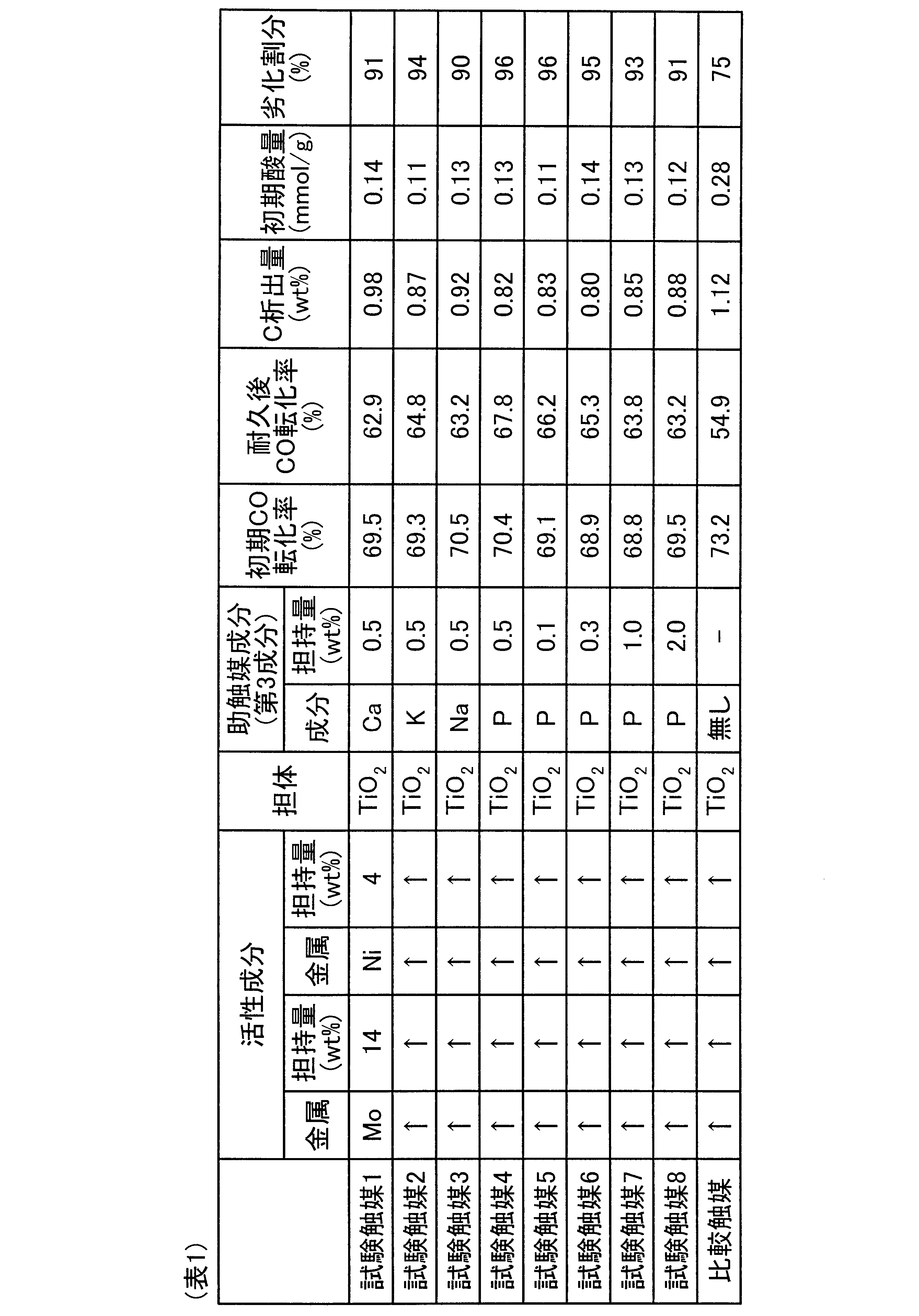
- Table 1 lists the composition of the catalyst and the test results.
- the catalysts 1 to 8 according to this test example have an initial acid amount reduced by adding a co-catalyst, and even after a low water vapor amount, after the endurance test for 100 hours. It was confirmed that the CO shift reaction was well maintained and the CO shift reaction was well maintained. In all the catalysts, the deterioration rate of the CO conversion rate was as good as 90% to 96%, and there was no significant decrease.
- the catalysts of Test Catalysts 2, 4 to 6 also had a small initial acid amount, and the decrease in the CO conversion after the 100-hour endurance test was extremely small.
- FIG. 2 is a graph comparing the initial CO conversion rate (%) in the durability test with the test catalyst 2 and the CO conversion rate (%) after 100 hours.
- the initial acid amount is as small as 0.11 mmol / g.
- the CO conversion rate is smaller than that of Comparative Catalyst 1 (73.2%) (69.3%), the carbon conversion in the endurance test is small. Compared with the result (54.9%), the deterioration rate was 64.8%, which was small (94%).
- the CO shift catalyst according to this test has added a promoter component such as Ca, K, P or the like as the third component, the initial acid amount can be reduced, and the amount of carbon (C) precipitation generated is small. It has been found that it has excellent durability and can maintain the CO shift reaction stably for a long period of time.
- a promoter component such as Ca, K, P or the like
- FIG. 3 is a diagram illustrating an example of a coal gasification power plant.
- the coal gasification power plant 50 includes a gasification furnace 11, a filter 13, a COS conversion device 51, a CO shift reaction device 20, and a gas purification device (H 2 S / CO 2 recovery device). ) 15 and a combined power generation facility 52.
- the gasification furnace 11 is supplied with coal as the fuel F and air 54 from the gasification air compressor 53, and the coal is gasified in the gasification furnace 11 to obtain the gasification gas 12 as the product gas.
- the air 54 is separated into nitrogen (N 2 ) and oxygen (O 2 ) by the air separation device 55, and N 2 and O 2 are appropriately supplied into the gasification furnace 11.
- the coal gasification power plant 50 supplies the gasification gas 12 obtained in the gasification furnace 11 to the filter 13, removes the dust, and then supplies the gas to the COS converter 51, and converts the COS contained in the gasification gas 12 to H. 2 Convert to S.
- the gasification gas 12 containing H 2 S is supplied to the CO shift reaction device 20 and the water vapor 21 is supplied into the CO shift reaction device 20, and the CO in the gasification gas 12 is converted into CO in the CO shift reaction device 20. causing a CO shift reaction to be converted to 2. Since the CO shift reaction apparatus 20 uses the CO shift catalyst according to the present invention, the reformed gas can be efficiently generated over a long period of time even if the amount of water vapor is greatly reduced as described above. it can.
- H 2 S / CO 2 recovery unit is a gas purification unit 15, H 2 S / in the CO 2 recovery device for removing CO 2 and H 2 S in the reformed gas.
- the purified gas 22 after being purified by the gas purifier 15 is supplied to the combined power generation facility 52.
- the combined power generation facility 52 includes a gas turbine 61, a steam turbine 62, a generator 63, and an exhaust heat recovery boiler (HRSG: Heat Recovery Steam Generator) 64.
- the combined power generation facility 52 supplies the purified gas 22 to the combustor 65 of the gas turbine 61 that is a power generation means. Further, the gas turbine 61 supplies the air 67 supplied to the compressor 66 to the combustor 65.
- the gas turbine 61 combusts the purified gas 22 in the combustor 65 to generate a high-temperature and high-pressure combustion gas 68, and the combustion gas 68 drives the turbine 69.
- the turbine 69 is connected to the generator 63, and the generator 63 generates electric power when the turbine 69 is driven. Since the exhaust gas 70 after driving the turbine 69 has a temperature of 500 to 600 ° C., it is sent to an exhaust heat recovery boiler (HRSG) 64 to recover thermal energy.
- HRSG exhaust heat recovery boiler
- steam 71 is generated by the thermal energy of the exhaust gas 70, and the steam turbine 62 is driven by the steam 71.
- the steam 71 is discharged from the steam turbine 62, cooled by the heat exchanger 72, and then supplied to the exhaust heat recovery boiler 64. Further, the exhaust gas 73 whose thermal energy has been recovered by the exhaust heat recovery boiler 64 is released into the atmosphere via the chimney 74 after NOx and the like in the exhaust gas 73 are removed by a denitration device (not shown) or the like. .
- the CO shift reaction can be carried out stably over a long period of time by converting CO contained in the gasification gas 12 into CO 2 . Thereby, in CO shift reaction, since CO shift reaction can be continued stably with little steam, the amount of steam extracted from HRSG 64 can be reduced, and the energy efficiency of coal gasification power plant 50 is improved. Can be performed.
- the CO shift reaction device 20 is limited to the case where it is installed between the COS conversion device 51 and the gas purification device (H 2 S / CO 2 recovery device) 15 (the front stage side of the H 2 S / CO 2 recovery device). However, it may be installed on the downstream side of the gas purification device (H 2 S / CO 2 recovery device) 15.
- the purified gas 22 discharged from the gas purification device (H 2 S / CO 2 recovery device) 15 is used as a gas for the turbine has been described.
- the purified gas 22 discharged from the gas purification device (H 2 S / CO 2 recovery device) 15 is used as a gas for the turbine.
- it may be used as a raw material gas for synthesizing a chemical product such as methanol and ammonia.
- the CO shift reaction apparatus 20 has been described with respect to the case where CO in the gasification gas 12 generated by gasifying the fuel F such as coal in the gasification furnace 11 is converted to CO 2 .
- the present invention is not limited to this, and can be similarly applied to, for example, a CO shift reactor for converting CO-containing gas into CO 2 in a fuel cell or the like.
Abstract
Description
一方、石炭を付加価値の高いエネルギー媒体として、変換するためには石炭ガス化技術、ガス精製技術などの高度な技術が必要とされる。
このガス化ガスを用いて発電する石炭ガス化複合発電システムが提案されている(特許文献1)。
CO+H2O⇔ CO2+H2+40.9kJ/mol (発熱反応) ・・・(1)
そこで、C析出への対策として、過剰の水蒸気量(水蒸気(H2O)/CO≧3)を添加する必要があった。
つまり、シフト反応器に供給しつつ水蒸気添加割合(H2O/CO)のための水蒸気添加源として、例えばHRSG(排熱回収ボイラ)よりの抽気中圧蒸気を用いているが、抽気水蒸気量を低減することが、プラント効率向上を図る上で重要な要素であるため、HRSG(排熱回収ボイラ)からの抽気水蒸気量をなるべく減らすことが、発電効率上昇の点から求められている。
図1に示すように、ガス化ガス精製システム10は、燃料Fである石炭をガス化するガス化炉11と、生成ガスであるガス化ガス12中の煤塵を除去するフィルタ13と、フィルタ13を通過した後のガス化ガス12中のハロゲンを除去する湿式スクラバ装置14と、熱交換後のガス化ガス12中のCO2及びH2Sを吸収除去する吸収塔15Aと再生する再生塔15Bからなると共に再生塔15B側に再生過熱器16を備えたガス精製装置15と、ガス化ガス12の温度を上げる第1の熱交換器17及び第2の熱交換器18と、温度が例えば300℃に上昇されたガス化ガス12中のCOをCO2に変換して精製ガス22とするCOシフト触媒19を備えたCOシフト反応装置20と、を具備するものである。なお、図1中、符号21は水蒸気を図示する。
次いで、水蒸気21が水蒸気供給装置(水蒸気供給手段)により供給された後、COシフト触媒19を有するCOシフト反応装置20に導入される。このCOシフト反応装置20により、ガス化ガス12中の一酸化炭素(CO)を改質し、COシフト触媒19下で二酸化炭素(CO2)に変換するようにしている。
また、これらの複合酸化物(例えばTiO2-SiO2、TiO2-ZrO2、TiO2-Al2O3、ZrO2-Al2O3、TiO2-CeO2、TiO2-La2O3等)としてもよい。
なお、リン(P)とマグネシウム(Mg)は、アルカリ金属又はアルカリ土類金属に属するものではないが、酸点を抑制する作用があるので、助触媒として用いることができる。
この結果、初期のCO転化率は、助触媒を添加しない従来触媒よりも若干低下するものの、例えば100時間耐久試験後のCO転化率は、従来触媒よりも高いものとなる。
その理由として、助触媒(第3成分)の添加により、触媒の持つ初期酸量を低下させた事により、炭素(C)析出量を低減できたためと推定される。
以下、本発明の効果を示す試験例について説明する。
1)試験触媒1の製法
石原産業製酸化チタン(TiO2(「MC-90」商品名))を100g磁製皿に入れ、150mlの水に溶かした硝酸ニッケル・6水和物(NN)とモリブデン酸アンモニウム・4水和物(MA)を、最終的に得られる全粉末量に対して、主活性成分(第1成分)としてMoO3が14重量%、副活性成分(第2成分)としてNiOが4重量%、助触媒(第3成分)としてCaが0.5重量%担持されるように添加後、磁製皿上で蒸発乾固含浸した。そして、得られた粉末を乾燥器で完全に乾燥後、500℃で3時間(昇温速度100℃/h)焼成を施すことにより粉末触媒を得た。
得られた粉末触媒を30tonの加圧成形器で粉末を固定化させた後、粒径が所定粒径(例えば2~4mm)の範囲となるように破砕後篩い分けして試験触媒1を得た。
試験触媒1の製造において、助触媒(第3成分)として、Caの替わりに、カリウム(K)を担持させた以外は、同様に操作して試験触媒2を得た。
試験触媒1の製造において、助触媒(第3成分)として、Caの替わりに、ナトリウム(Na)を担持させた以外は、同様に操作して試験触媒3を得た。
試験触媒1の製造において、助触媒(第3成分)として、Caの替わりに、リン(P)を担持させた以外は、同様に操作して試験触媒4を得た。
試験触媒4の製造において、助触媒(第3成分)として、リン(P)の担持量を0.1重量%と変更した以外は、同様に操作して試験触媒5を得た。
試験触媒4の製造において、助触媒(第3成分)として、リン(P)の担持量を0.3重量%と変更した以外は、同様に操作して試験触媒6を得た。
試験触媒4の製造において、助触媒(第3成分)として、リン(P)の担持量を1.0重量%と変更した以外は、同様に操作して試験触媒7を得た。
試験触媒4の製造において、助触媒(第3成分)として、リン(P)の担持量を2.0重量%と変更した以外は、同様に操作して試験触媒8を得た。
試験触媒1の製造において、助触媒(第3成分)を添加しない以外は、同様に操作して比較触媒を得た。
評価試験は、内径14mmの管型反応管に触媒を3.3cc充填し、流通式マイクロリアクタ装置により触媒活性を評価した。
初期の触媒活性の比較は、触媒層入口、出口のガス流量変化のCO転化率を求めた。
ガス組成は、H2/CO/CO2=30/50/20モル%、H2S=700ppm、S/CO=1.0とし、0.9MPa、温度250℃、SV=6、000h-1の条件で試験した。
CO転化率(%)=(1-(触媒層出口COガス流速(mol/時間))/(触媒層入口COガス流速(mol/時間)))×100・・・(I)
ガス組成は、H2/CO/CO2=30/50/20モル%、H2S=700ppm、S/CO=0.1とし、0.9MPa、温度450℃、SV=2、000h-1の条件で試験した。
いずれの触媒もCO転化率の劣化割合は90%~96%と良好であり、大幅な低下はなかった。
図2により明らかなように、試験触媒2は、助触媒としてKを添加しているので、初期の酸量は、0.11mmol/gと小さい。なお、CO転化率は比較触媒1(73.2%)より小さい(69.3%)ものの、耐久試験で炭素析出が少ないので、100時間経過後のCO転化率(%)は、比較触媒1の結果(54.9%)に較べて、64.8%とその劣化割合は小さい(94%)ものであった。
本実施例に係るCOシフト反応装置20を備えた石炭ガス化発電プラントについて、図面を参照して説明する。図3は、石炭ガス化発電プラントの一例を示す図である。図3に示すように、石炭ガス化発電プラント50は、ガス化炉11と、フィルタ13と、COS変換装置51と、COシフト反応装置20と、ガス精製装置(H2S/CO2回収装置)15と、複合発電設備52とを有する。
その後、H2Sを含むガス化ガス12をCOシフト反応装置20に供給すると共に水蒸気21をCOシフト反応装置20内に供給し、COシフト反応装置20内でガス化ガス12中のCOをCO2に変換するCOシフト反応を起こさせる。
このCOシフト反応装置20では、本発明にかかるCOシフト触媒を用いているので、上述の通り水蒸気量を大幅に低減させても、改質ガスを長期間に亙って効率よく生成することができる。
COシフト反応装置20でガス化ガス12中のCOをCO2に変換した後、得られた改質ガスをガス精製装置15であるH2S/CO2回収装置に供給し、H2S/CO2回収装置で改質ガス中のCO2及びH2Sを除去する。
これにより、COシフト反応において、少ない水蒸気で安定してCOシフト反応を継続することができるので、HRSG64から抽気する水蒸気量を減らすことができ、石炭ガス化発電プラント50のエネルギー効率が向上した運転を行うことが可能となる。
11 ガス化炉
12 ガス化ガス
13 フィルタ
14 湿式スクラバ装置
15A 吸収塔
15B 再生塔
15 ガス精製装置
19 COシフト触媒
20 COシフト反応装置
21 水蒸気
22 精製ガス
Claims (4)
- ガス中の一酸化炭素(CO)を改質するCOシフト触媒であって、
モリブデン(Mo)又は鉄(Fe)のいずれか一種を主成分とすると共に、
ニッケル(Ni)又はルテニウム(Ru)のいずれか一種を副成分とする活性成分と、
カルシウム(Ca)、カリウム(K)、ナトリウム(Na)、リン(P)及びマグネシウム(Mg)いずれか一種を成分とする助触媒成分と、
この活性成分及び助触媒成分を担持するチタン(Ti)、ジルコニウム(Zr)及びセリウム(Ce)のいずれか一種又は二種以上の酸化物からなる担体とからなることを特徴とするCOシフト触媒。 - 請求項1において、
前記活性成分の主成分の担持量が0.1~25重量%であり、副成分の担持量が0.01~10重量%であると共に、助触媒成分の担持量が0.1~2.0重量%であることを特徴とするCOシフト触媒。 - 請求項1又は2のCOシフト触媒を反応塔内に充填してなることを特徴とするCOシフト反応装置。
- ガス化炉で得られたガス化ガス中の煤塵をフィルタで除去した後、
湿式スクラバ装置によりさらにCOシフト反応後のガス化ガスを浄化し、
次いで、ガス化ガス中の二酸化炭素及び硫化水素を除去し、
請求項1又は2のCOシフト触媒を用いて、
ガス化ガス中のCOをCO2に変換するCOシフト反応させ、精製ガスを得ることを特徴とするガス化ガスの精製方法。
Priority Applications (6)
| Application Number | Priority Date | Filing Date | Title |
|---|---|---|---|
| EP12891018.9A EP2939739B1 (en) | 2012-12-28 | 2012-12-28 | Co shift catalyst |
| JP2014554049A JPWO2014103074A1 (ja) | 2012-12-28 | 2012-12-28 | Coシフト触媒、coシフト反応装置及びガス化ガスの精製方法 |
| AU2012397688A AU2012397688B2 (en) | 2012-12-28 | 2012-12-28 | CO shift catalyst, CO shift reactor, and method for purifying gasification gas |
| PCT/JP2012/084230 WO2014103074A1 (ja) | 2012-12-28 | 2012-12-28 | Coシフト触媒、coシフト反応装置及びガス化ガスの精製方法 |
| CN201280074990.2A CN104507572B (zh) | 2012-12-28 | 2012-12-28 | Co转化催化剂、co转化反应装置及气化气的精制方法 |
| US14/418,651 US20150291899A1 (en) | 2012-12-28 | 2012-12-28 | Co shift catalyst, co shift reactor, and method for purifying gasification gas |
Applications Claiming Priority (1)
| Application Number | Priority Date | Filing Date | Title |
|---|---|---|---|
| PCT/JP2012/084230 WO2014103074A1 (ja) | 2012-12-28 | 2012-12-28 | Coシフト触媒、coシフト反応装置及びガス化ガスの精製方法 |
Publications (1)
| Publication Number | Publication Date |
|---|---|
| WO2014103074A1 true WO2014103074A1 (ja) | 2014-07-03 |
Family
ID=51020219
Family Applications (1)
| Application Number | Title | Priority Date | Filing Date |
|---|---|---|---|
| PCT/JP2012/084230 WO2014103074A1 (ja) | 2012-12-28 | 2012-12-28 | Coシフト触媒、coシフト反応装置及びガス化ガスの精製方法 |
Country Status (6)
| Country | Link |
|---|---|
| US (1) | US20150291899A1 (ja) |
| EP (1) | EP2939739B1 (ja) |
| JP (1) | JPWO2014103074A1 (ja) |
| CN (1) | CN104507572B (ja) |
| AU (1) | AU2012397688B2 (ja) |
| WO (1) | WO2014103074A1 (ja) |
Families Citing this family (3)
| Publication number | Priority date | Publication date | Assignee | Title |
|---|---|---|---|---|
| US10774278B2 (en) | 2013-02-27 | 2020-09-15 | Mitsubishi Heavy Industries Engineering, Ltd. | CO shift catalyst, CO shift reaction apparatus, and method for purifying gasified gas |
| CN104994944A (zh) * | 2013-02-27 | 2015-10-21 | 三菱重工业株式会社 | Co转化催化剂、co转化反应装置和气化气的精制方法 |
| CN111770793A (zh) * | 2018-05-29 | 2020-10-13 | 积水化学工业株式会社 | 催化剂、二氧化碳还原方法以及二氧化碳还原装置 |
Citations (9)
| Publication number | Priority date | Publication date | Assignee | Title |
|---|---|---|---|---|
| JPS508038B1 (ja) * | 1969-11-10 | 1975-04-01 | ||
| CA1151135A (en) * | 1979-11-12 | 1983-08-02 | Jean C. Clement | Process for the preparation of a catalyst |
| JPS58214342A (ja) * | 1982-06-08 | 1983-12-13 | バスフ アクチェン ゲゼルシャフト | 含硫黄ガスの変換用触媒 |
| CN1096494A (zh) * | 1993-06-17 | 1994-12-21 | 中国石油化工总公司 | 耐硫一氧化碳变换催化剂和制法 |
| JPH08173809A (ja) * | 1994-12-16 | 1996-07-09 | China Petrochem Corp | 一酸化炭素の転化のための触媒およびそれを用いた方法 |
| JP2004331701A (ja) | 2003-04-30 | 2004-11-25 | Clean Coal Power R & D Co Ltd | 石炭ガス化プラント、および石炭ガス化方法並びに石炭ガス化発電プラント |
| JP2008104906A (ja) * | 2006-10-23 | 2008-05-08 | Catalysts & Chem Ind Co Ltd | 一酸化炭素除去用触媒の製造方法 |
| JP2011157486A (ja) | 2010-02-01 | 2011-08-18 | Mitsubishi Heavy Ind Ltd | ガス化ガス精製システム |
| WO2011105501A1 (ja) * | 2010-02-24 | 2011-09-01 | 三菱重工業株式会社 | Coシフト触媒、coシフト反応装置及びガス化ガスの精製方法 |
Family Cites Families (16)
| Publication number | Priority date | Publication date | Assignee | Title |
|---|---|---|---|---|
| US2662090A (en) * | 1949-10-27 | 1953-12-08 | Standard Oil Dev Co | Hydrocarbon synthesis |
| GB1281051A (en) * | 1968-06-18 | 1972-07-12 | Exxon Research Engineering Co | Low temperature shift reaction involving an alkali metal compound and a hydrogenation dehydrogenation component |
| BE758677A (fr) * | 1969-11-10 | 1971-05-10 | Exxon Research Engineering Co | Nouveau catalyseur pour la production de l'hydrogene par deplacement dugaz a l'eau |
| GB1491499A (en) * | 1973-11-23 | 1977-11-09 | Exxon Research Engineering Co | Process and catalyst for conversion of carbon monoxide and steam to hydrogen and carbon dioxide |
| US4153671A (en) * | 1977-01-13 | 1979-05-08 | Nalco Chemical Company | Catalytic gas purification process |
| US4389335A (en) * | 1981-04-14 | 1983-06-21 | United Catalysts Inc. | Catalyst for carbon monoxide conversion in sour gas |
| US4452854A (en) * | 1981-04-14 | 1984-06-05 | United Catalysts, Inc. | Catalyst and process for carbon monoxide conversion in sour gas |
| US4381993A (en) * | 1981-10-14 | 1983-05-03 | Standard Oil Company (Indiana) | Process for treating hydrocarbon feedstocks with CO and H2 O in the presence of steam stable catalysts |
| FR2575453B1 (fr) * | 1984-12-28 | 1990-03-02 | Pro Catalyse | Procede de conversion du monoxyde de carbone par la vapeur d'eau a l'aide d'un catalyseur thioresistant |
| JP2006511425A (ja) * | 2002-12-20 | 2006-04-06 | 本田技研工業株式会社 | 白金を含まない水素生成用ルテニウム−コバルト触媒配合物 |
| US7790018B2 (en) * | 2005-05-11 | 2010-09-07 | Saudia Arabian Oil Company | Methods for making higher value products from sulfur containing crude oil |
| JP5319934B2 (ja) * | 2008-02-28 | 2013-10-16 | 三菱重工業株式会社 | 排ガス処理方法及び装置 |
| CN101723802B (zh) * | 2008-10-24 | 2013-06-19 | 中国科学院大连化学物理研究所 | 一种纤维素制乙二醇的方法 |
| CA2805259A1 (en) * | 2010-08-26 | 2012-03-01 | Basf Se | Highly active water gas shift catalyst, preparation process and use thereof |
| GB201109376D0 (en) * | 2011-06-06 | 2011-07-20 | Johnson Matthey Plc | Water-gas shift catalyst |
| JP5705156B2 (ja) * | 2012-03-30 | 2015-04-22 | 三菱日立パワーシステムズ株式会社 | ガス精製方法及び石炭ガス化プラント |
-
2012
- 2012-12-28 EP EP12891018.9A patent/EP2939739B1/en active Active
- 2012-12-28 JP JP2014554049A patent/JPWO2014103074A1/ja active Pending
- 2012-12-28 US US14/418,651 patent/US20150291899A1/en not_active Abandoned
- 2012-12-28 AU AU2012397688A patent/AU2012397688B2/en active Active
- 2012-12-28 CN CN201280074990.2A patent/CN104507572B/zh active Active
- 2012-12-28 WO PCT/JP2012/084230 patent/WO2014103074A1/ja active Application Filing
Patent Citations (9)
| Publication number | Priority date | Publication date | Assignee | Title |
|---|---|---|---|---|
| JPS508038B1 (ja) * | 1969-11-10 | 1975-04-01 | ||
| CA1151135A (en) * | 1979-11-12 | 1983-08-02 | Jean C. Clement | Process for the preparation of a catalyst |
| JPS58214342A (ja) * | 1982-06-08 | 1983-12-13 | バスフ アクチェン ゲゼルシャフト | 含硫黄ガスの変換用触媒 |
| CN1096494A (zh) * | 1993-06-17 | 1994-12-21 | 中国石油化工总公司 | 耐硫一氧化碳变换催化剂和制法 |
| JPH08173809A (ja) * | 1994-12-16 | 1996-07-09 | China Petrochem Corp | 一酸化炭素の転化のための触媒およびそれを用いた方法 |
| JP2004331701A (ja) | 2003-04-30 | 2004-11-25 | Clean Coal Power R & D Co Ltd | 石炭ガス化プラント、および石炭ガス化方法並びに石炭ガス化発電プラント |
| JP2008104906A (ja) * | 2006-10-23 | 2008-05-08 | Catalysts & Chem Ind Co Ltd | 一酸化炭素除去用触媒の製造方法 |
| JP2011157486A (ja) | 2010-02-01 | 2011-08-18 | Mitsubishi Heavy Ind Ltd | ガス化ガス精製システム |
| WO2011105501A1 (ja) * | 2010-02-24 | 2011-09-01 | 三菱重工業株式会社 | Coシフト触媒、coシフト反応装置及びガス化ガスの精製方法 |
Non-Patent Citations (3)
| Title |
|---|
| KOJI TSUCHIMOTO ET AL.: "Ryuka Suiso Sonzaika deno Issankatanso to Suijoki no Hanno ni Okeru MoO3·MgO-kei Shokubai no Kassei", THE JOURNAL OF CHEMICAL INDUSTRY, vol. 71, no. 9, 1968, pages 1488 - 1492, XP055184990 * |
| NEWSOME, D. S.: "The water-gas shift reaction", CATAL. REV. SCI. ENG., vol. 21, no. 2, 16 September 1980 (1980-09-16), pages 275 - 318, XP008176054 * |
| See also references of EP2939739A4 |
Also Published As
| Publication number | Publication date |
|---|---|
| EP2939739B1 (en) | 2023-12-20 |
| EP2939739A4 (en) | 2016-12-28 |
| CN104507572A (zh) | 2015-04-08 |
| CN104507572B (zh) | 2018-06-22 |
| EP2939739A1 (en) | 2015-11-04 |
| US20150291899A1 (en) | 2015-10-15 |
| AU2012397688B2 (en) | 2016-05-26 |
| AU2012397688A1 (en) | 2015-02-26 |
| JPWO2014103074A1 (ja) | 2017-01-12 |
Similar Documents
| Publication | Publication Date | Title |
|---|---|---|
| JP6005251B2 (ja) | Coシフト触媒の製造方法及びガス化ガスの精製方法 | |
| JP5550715B2 (ja) | Coシフト触媒、coシフト反応装置及びガス化ガスの精製方法 | |
| JP5404774B2 (ja) | Coシフト触媒、coシフト反応装置及びガス化ガスの精製方法 | |
| WO2014103074A1 (ja) | Coシフト触媒、coシフト反応装置及びガス化ガスの精製方法 | |
| JP5968465B2 (ja) | Coシフト触媒、coシフト反応装置及びガス化ガスの精製方法 | |
| JP6025870B2 (ja) | Coシフト触媒、coシフト反応装置及びガス化ガスの精製方法 | |
| US10774278B2 (en) | CO shift catalyst, CO shift reaction apparatus, and method for purifying gasified gas | |
| AU2009346342B2 (en) | CO shift catalyst, method for producing the same, and CO shift reactor using CO shift catalyst |
Legal Events
| Date | Code | Title | Description |
|---|---|---|---|
| 121 | Ep: the epo has been informed by wipo that ep was designated in this application |
Ref document number: 12891018 Country of ref document: EP Kind code of ref document: A1 |
|
| WWE | Wipo information: entry into national phase |
Ref document number: 14418651 Country of ref document: US Ref document number: IDP00201500564 Country of ref document: ID Ref document number: 2012891018 Country of ref document: EP |
|
| ENP | Entry into the national phase |
Ref document number: 2014554049 Country of ref document: JP Kind code of ref document: A |
|
| ENP | Entry into the national phase |
Ref document number: 2012397688 Country of ref document: AU Date of ref document: 20121228 Kind code of ref document: A |
|
| NENP | Non-entry into the national phase |
Ref country code: DE |