WO2011074080A1 - 冷間圧延材製造設備および冷間圧延方法 - Google Patents
冷間圧延材製造設備および冷間圧延方法 Download PDFInfo
- Publication number
- WO2011074080A1 WO2011074080A1 PCT/JP2009/070926 JP2009070926W WO2011074080A1 WO 2011074080 A1 WO2011074080 A1 WO 2011074080A1 JP 2009070926 W JP2009070926 W JP 2009070926W WO 2011074080 A1 WO2011074080 A1 WO 2011074080A1
- Authority
- WO
- WIPO (PCT)
- Prior art keywords
- coil
- cold rolling
- strip
- rolling
- reversible
- Prior art date
- Legal status (The legal status is an assumption and is not a legal conclusion. Google has not performed a legal analysis and makes no representation as to the accuracy of the status listed.)
- Ceased
Links
Images


Classifications
-
- B—PERFORMING OPERATIONS; TRANSPORTING
- B21—MECHANICAL METAL-WORKING WITHOUT ESSENTIALLY REMOVING MATERIAL; PUNCHING METAL
- B21B—ROLLING OF METAL
- B21B1/00—Metal-rolling methods or mills for making semi-finished products of solid or profiled cross-section; Sequence of operations in milling trains; Layout of rolling-mill plant, e.g. grouping of stands; Succession of passes or of sectional pass alternations
- B21B1/22—Metal-rolling methods or mills for making semi-finished products of solid or profiled cross-section; Sequence of operations in milling trains; Layout of rolling-mill plant, e.g. grouping of stands; Succession of passes or of sectional pass alternations for rolling plates, strips, bands or sheets of indefinite length
- B21B1/30—Metal-rolling methods or mills for making semi-finished products of solid or profiled cross-section; Sequence of operations in milling trains; Layout of rolling-mill plant, e.g. grouping of stands; Succession of passes or of sectional pass alternations for rolling plates, strips, bands or sheets of indefinite length in a non-continuous process
- B21B1/32—Metal-rolling methods or mills for making semi-finished products of solid or profiled cross-section; Sequence of operations in milling trains; Layout of rolling-mill plant, e.g. grouping of stands; Succession of passes or of sectional pass alternations for rolling plates, strips, bands or sheets of indefinite length in a non-continuous process in reversing single stand mills, e.g. with intermediate storage reels for accumulating work
- B21B1/36—Metal-rolling methods or mills for making semi-finished products of solid or profiled cross-section; Sequence of operations in milling trains; Layout of rolling-mill plant, e.g. grouping of stands; Succession of passes or of sectional pass alternations for rolling plates, strips, bands or sheets of indefinite length in a non-continuous process in reversing single stand mills, e.g. with intermediate storage reels for accumulating work by cold-rolling
-
- B—PERFORMING OPERATIONS; TRANSPORTING
- B21—MECHANICAL METAL-WORKING WITHOUT ESSENTIALLY REMOVING MATERIAL; PUNCHING METAL
- B21C—MANUFACTURE OF METAL SHEETS, WIRE, RODS, TUBES, PROFILES OR LIKE SEMI-MANUFACTURED PRODUCTS OTHERWISE THAN BY ROLLING; AUXILIARY OPERATIONS USED IN CONNECTION WITH METAL-WORKING WITHOUT ESSENTIALLY REMOVING MATERIAL
- B21C47/00—Winding-up, coiling or winding-off metal wire, metal band or other flexible metal material characterised by features relevant to metal processing only
- B21C47/24—Transferring coils to or from winding apparatus or to or from operative position therein; Preventing uncoiling during transfer
- B21C47/247—Joining wire or band ends
-
- B—PERFORMING OPERATIONS; TRANSPORTING
- B21—MECHANICAL METAL-WORKING WITHOUT ESSENTIALLY REMOVING MATERIAL; PUNCHING METAL
- B21B—ROLLING OF METAL
- B21B15/00—Arrangements for performing additional metal-working operations specially combined with or arranged in, or specially adapted for use in connection with, metal-rolling mills
-
- B—PERFORMING OPERATIONS; TRANSPORTING
- B21—MECHANICAL METAL-WORKING WITHOUT ESSENTIALLY REMOVING MATERIAL; PUNCHING METAL
- B21B—ROLLING OF METAL
- B21B37/00—Control devices or methods specially adapted for metal-rolling mills or the work produced thereby
- B21B37/16—Control of thickness, width, diameter or other transverse dimensions
- B21B37/18—Automatic gauge control
-
- B—PERFORMING OPERATIONS; TRANSPORTING
- B21—MECHANICAL METAL-WORKING WITHOUT ESSENTIALLY REMOVING MATERIAL; PUNCHING METAL
- B21B—ROLLING OF METAL
- B21B37/00—Control devices or methods specially adapted for metal-rolling mills or the work produced thereby
- B21B37/28—Control of flatness or profile during rolling of strip, sheets or plates
- B21B37/38—Control of flatness or profile during rolling of strip, sheets or plates using roll bending
-
- B—PERFORMING OPERATIONS; TRANSPORTING
- B21—MECHANICAL METAL-WORKING WITHOUT ESSENTIALLY REMOVING MATERIAL; PUNCHING METAL
- B21B—ROLLING OF METAL
- B21B15/00—Arrangements for performing additional metal-working operations specially combined with or arranged in, or specially adapted for use in connection with, metal-rolling mills
- B21B15/0085—Joining ends of material to continuous strip, bar or sheet
-
- B—PERFORMING OPERATIONS; TRANSPORTING
- B21—MECHANICAL METAL-WORKING WITHOUT ESSENTIALLY REMOVING MATERIAL; PUNCHING METAL
- B21B—ROLLING OF METAL
- B21B15/00—Arrangements for performing additional metal-working operations specially combined with or arranged in, or specially adapted for use in connection with, metal-rolling mills
- B21B15/0007—Cutting or shearing the product
- B21B2015/0014—Cutting or shearing the product transversely to the rolling direction
-
- B—PERFORMING OPERATIONS; TRANSPORTING
- B21—MECHANICAL METAL-WORKING WITHOUT ESSENTIALLY REMOVING MATERIAL; PUNCHING METAL
- B21B—ROLLING OF METAL
- B21B15/00—Arrangements for performing additional metal-working operations specially combined with or arranged in, or specially adapted for use in connection with, metal-rolling mills
- B21B2015/0057—Coiling the rolled product
-
- B—PERFORMING OPERATIONS; TRANSPORTING
- B21—MECHANICAL METAL-WORKING WITHOUT ESSENTIALLY REMOVING MATERIAL; PUNCHING METAL
- B21B—ROLLING OF METAL
- B21B15/00—Arrangements for performing additional metal-working operations specially combined with or arranged in, or specially adapted for use in connection with, metal-rolling mills
- B21B2015/0064—Uncoiling the rolled product
-
- B—PERFORMING OPERATIONS; TRANSPORTING
- B21—MECHANICAL METAL-WORKING WITHOUT ESSENTIALLY REMOVING MATERIAL; PUNCHING METAL
- B21B—ROLLING OF METAL
- B21B2263/00—Shape of product
- B21B2263/20—End shape; fish tail; tongue
-
- B—PERFORMING OPERATIONS; TRANSPORTING
- B21—MECHANICAL METAL-WORKING WITHOUT ESSENTIALLY REMOVING MATERIAL; PUNCHING METAL
- B21B—ROLLING OF METAL
- B21B2265/00—Forming parameters
- B21B2265/02—Tension
-
- B—PERFORMING OPERATIONS; TRANSPORTING
- B21—MECHANICAL METAL-WORKING WITHOUT ESSENTIALLY REMOVING MATERIAL; PUNCHING METAL
- B21B—ROLLING OF METAL
- B21B2275/00—Mill drive parameters
- B21B2275/02—Speed
- B21B2275/06—Product speed
Definitions
- the present invention relates to a cold rolling material manufacturing facility and a cold rolling method.
- a strip take-up and take-out device that doubles as unwinding is disposed, and the strip is reversibly rolled between the take-up and take-out device on the entry side and the take-out side of the cold rolling mill until the desired plate thickness is achieved.
- a reversible cold rolling facility hereinafter referred to as an RCM facility for rolling has been put to practical use.
- Patent Document 1 there is a facility (hereinafter referred to as a two-stand reverse facility) equipped with two rolling mills in an attempt to increase the annual production volume of the RCM facility from 500,000 tons to about 600,000 tons (Patent Document 1) reference).
- the tip of the strip is passed unrolled, and the pass switching portion is used in the third pass and subsequent passes. Then we have to leave the front pass rolling section unrolled. For this reason, there is a problem that the strip end and the unrolled portion at the tail end are out of the product thickness range and can not be sold as a product. Strips outside these product thickness are called off gauges.
- the ratio of the off gauge is defined as the off gauge ratio as the ratio of the off gauge amount to the total production volume.
- the off-gage rate in each rolling mill is approximately 2.5% in the RCM plant and approximately 6.0% in the two-stand reverse plant.
- the off-gauge rate of the PL-TCM facility in which the pickling process and the cold tandem rolling process are continuous is only about 0.2%.
- the problem is that the off-gage rate is very high, about 2.5% to 6.0%, compared to the PL-TCM facility.
- the rolling mill is decelerated when the coil trailing end is approached in the front pass, and the rolling is stopped. In the next pass, acceleration is newly performed in order to roll in the opposite direction of the previous pass.
- acceleration / deceleration and rolling stop are repeated as many times as the number of passes until the desired product thickness is achieved, so the actual rolling time occupied in the operation time is short, and the production efficiency is poor.
- a coil buildup line that joins a plurality of coils to form a long single coil and a long coil (buildup coil) built up are reversibly rolled a predetermined number of times with a cold rolling mill
- a cold rolling facility which has a reversible rolling line for carrying out and is divided into coil lengths that can be transported in the final pass (see Patent Document 2).
- the strip length of the build-up coil can be increased to correspond to the total strip length of a plurality of joined coils, and the unrolled portion at the coil tip end portion is the innermost periphery of the built-up coil Since it occurs only in the part and the outermost part, it is possible to significantly reduce the off gauge ratio.
- the number of accelerations / decelerations associated with the switching of the rolling direction can be reduced by the number of joined coils, the production efficiency is improved.
- Patent No. 3322984 Japanese Patent Publication No. 57-039844
- Patent Document 2 solves the problems of the prior art described in Patent Document 1 and enables high efficiency and high yield, but has the following problems.
- the first problem is the complication of the configuration and the enlargement of the device.
- Patent Document 2 The prior art described in Patent Document 2 is to build up a plurality of coils and form an elongated build-up coil.
- the outer diameter of the coil becomes large, and the tension of rolling applied to the coil increases the coil winding tightening force to be contracted toward the inner diameter side of the coil.
- a collapsible reel having a variable diameter is applied to the winding and unwinding device, it becomes difficult to give the reel a strength for holding the tightening force. That is, it is difficult to apply a collapsible reel to a take-up and unwinding device, and in order to avoid this problem, it is necessary to apply a solid block-type reel whose diameter is not variable.
- joining devices applied to cold rolling applications are a laser beam welder and a flash butt welder, which are a butt joint method.
- These welders use a large number of high-rigidity and high-precision parts in order to ensure high butt accuracy, making the equipment large and expensive compared to other joining methods.
- PL-TCM large-scale production facilities exceeding 1 million tons
- the ratio of welding machine costs to the total equipment investment costs becomes relatively low, which becomes a problem
- the ratio becomes large, which causes a problem in cost-effectiveness and is difficult to apply.
- the second problem is the increase in size of the coil.
- Patent Document 2 forms a build-up coil, and the build-up coil becomes longer.
- the torque required for the reel increases in a form that is linearly proportional to the coil outer diameter, and the problem that the drive device for the reel becomes large was there.
- the drive device of the reel is enlarged, the winding and unwinding device is also enlarged, and the initial cost is increased as in the first problem.
- the stop mark may not be noticeable to a level that can not be visually observed by continuing rolling a plurality of times. However, if it occurs in the final pass, the quality of the surface gloss is impaired, and the material of strict quality has the problem of becoming a defective product.
- the coil carried into the unwinding device may have an uneven coil end face. That is, the end face of the coil may be shaped like a telescope (telescope state).
- a telescope telescope state
- Unrolling the strip of the telescopic coil causes the strip to serpentine, and not only the desired strip shape can not be obtained, but there may also be a risk of strip breakage by rolling unevenly.
- Patent Document 2 the prior art described in Patent Document 2 is to form an elongated build-up coil, and the problem of the telescopic state becomes remarkable as the ratio of the coil outer diameter to the strip width increases.
- each coil to be built up has no thickness change, but in practice the plate thickness of the preceding coil and the plate thickness of the following coil may be slightly different due to manufacturing errors, etc.
- a step is generated at the joint. When tension is applied to the coil in the state where the junction having a steep step is positioned in the inner layer of the buildup coil, the step on the junction is transferred to the inside and the outside of each layer, causing a product defect to be treated as wrinkles. there were.
- a cold-rolled steel plate as a cold-rolled material
- a high quality electromagnetic steel plate and a magnesium plate may be rolled, and stable joining is desired.
- the object of the present invention is to provide a cold-rolled material facility and a cold-rolled material facility which maintain high efficiency, high yield, and have an excellent investment cost-effectiveness in small-to-medium scale production facilities with annual production of 300,000 to 600,000 tons
- An inter-rolling method is to be provided.
- the reversible cold rolling method according to the first aspect of the present invention for solving the first to third problems described above comprises sequentially unwinding a strip from a plurality of coils to be subjected to a rolling process and welding the strip.
- Coil build-up process by the coil a reversible rolling process in which the strip unrolled from the build-up coil is reversibly rolled a predetermined number of times in a rolling mill, and a desired strip length in the final pass of the reversible rolling process
- the coil outer diameter of the buildup coil is set to ⁇ 3000 or less
- the rolling mill is a rolling mill.
- the rolling speed of is set to be more than 0 mpm and not more than 50 mpm.
- a reversible cold rolling method according to a second aspect of the present invention for solving the second problem described above is the reverse cold rolling method according to the first aspect, wherein the outer diameter of the buildup coil is large when the outer diameter is large. It is characterized in that the tension is set lower gradually as compared to the tension of the strip at the time of small diameter.
- a reversible cold rolling method according to a third aspect of the present invention for solving the first problem described above is the reversible cold rolling method according to any one of the first aspect to the second aspect of the present invention. At the end of the first pass, cutting the tail end bend portion of the strip unwound from the buildup coil.
- the thickness gauge used for thickness control is installed at a distance from the work roll of the rolling mill, and when the rolling speed is reduced, feedback control of the thickness is performed by the measurement value of the thickness gauge.
- the plate thickness control accuracy is reduced due to the time delay and the time delay.
- the reversible cold rolling method according to a fourth aspect of the present invention for solving the above-described newly occurring problem is the rolling method according to any one of the first through the third aspects of the present invention, wherein The incoming rolling speed of the machine, and the incoming plate thickness and outgoing rolling speed are measured, and based on these measured values, the thickness immediately below the work roll of the rolling mill is calculated, and the hydraulic pressure reduction device of the rolling mill is used. It is characterized in that the plate thickness is controlled so as to obtain a desired plate thickness.
- the shape control accuracy is reduced. That is, since the shape detector for measuring the shape of the strip is also disposed at a position separated from the work roll of the rolling mill in the same manner as the thickness gauge, when the rolling speed is reduced, the shape by the shape detector It takes time from the recognition of the shape to the correction of the shape by the actuator, and the shape control accuracy is lowered. In general, when the rolling speed is reduced, the friction coefficient between the work roll and the strip is increased, and as a result, the rolling load is increased and the shape is disturbed.
- a reversible cold rolling method for solving the above-mentioned newly occurring problem is the dividing step according to any one of the first to fourth aspects of the present invention.
- the strip shape is controlled by roll bender control and / or coolant control based on the result of roll deflection calculation due to fluctuation of the rolling load of the rolling mill.
- the precision may be insufficient in conventional plate thickness control.
- a reversible cold rolling method for solving the above-described newly occurring problem is a thickness gauge according to any one of the first through fifth aspects of the present invention. Is provided on the downstream side of the joining device for welding in the coil build-up process, and in the coil build-up process, the thickness gauge measures the thickness of the plate after joining, and in the first pass of the reversible rolling process , Feed-forward thickness control.
- a reversible cold rolling method according to a seventh invention for solving the fourth problem described above is a coil buildup for a reversible cold rolling method according to any one of the first invention to the sixth invention.
- the winding and unwinding device winds up and unwinds the buildup coil, and has a coil centering mechanism, and the coil buildup winding and unwinding device winds up the buildup coil in the coil buildup process.
- the coil centering mechanism is operated at the time of picking, and in the first pass of the reversible rolling process, the coil buildup take-up and unwinding device operates the coil centering mechanism when unwinding a buildup coil.
- the coil buildup Before the process, the order of the coils to be carried in is adjusted in advance so that the absolute value of the plate thickness difference between the preceding coil and the following coil is 1 mm or less.
- the reversible cold rolling method according to a ninth aspect of the present invention for solving the first and fifth problems described above is the reversible cold rolling method according to any one of the first aspect to the eighth aspect of the present invention.
- the bonding is performed by mash seam welding.
- the mash seam welding machine adopts a method in which the materials to be joined are sandwiched between the overlapping electrode wheels and energized to cause contact resistance and internal resistance heat generation of the materials to join them. Thereby, the plate thickness of the bonding portion after the end of bonding is increased to about 1.2 to 1.5 times.
- the thickened joint becomes a step, and when passing through the rolling mill, an excessive force acts on the roll. Furthermore, the step may be transferred to the work roll as a mark. That is, the same problem as the fifth problem occurs.
- a reversible cold rolling method for solving the same problem as the above-described fifth problem that arises according to the fifth aspect is the reversible cold according to any one of the first aspect to the ninth aspect.
- the cross swaging process is performed immediately after the joining by the mash seam welding method.
- a reversible cold rolling method according to any one of the first to tenth aspects, wherein the cutting device divides the coil in the dividing step.
- the portion where the coil is divided is set immediately after the joint passes through the cutting device.
- a reversible cold rolling method is the reversible cold rolling method according to the eleventh aspect, wherein, in the dividing step, immediately before the joining portion passes the cutting device at a portion where the coil is divided. , It is characterized in that it is done immediately after the joint passes through the cutting device.
- a reversible cold rolling method according to a thirteenth invention is the reversible cold rolling method according to any one of the first invention to the twelfth invention, wherein the joining device welds the strip by welding.
- a strip heating device is provided, and in the coil build-up process, the strip heating device heats the strip to 100 ° C. or more and 400 ° C. or less.
- a reversible cold rolling method according to a fourteenth invention is characterized in that, in the reversible cold rolling method according to any one of the first invention to the thirteenth invention, the rolling mill has two stands. .
- the reversible cold rolling method according to the fifteenth invention is the reversible cold rolling method according to any one of the first invention to the fourteenth invention, wherein the strip is formed before the start of the final pass of the reversible rolling process. It is characterized in that the work rolls are rearranged into the work rolls for dulling in the passed state, and the final pass rolling is performed.
- a coil build-up take-up and take-out apparatus which forms an up coil and takes up and takes out a strip of the build-up coil, and a joining apparatus disposed between the take-out apparatus and the coil build-up take-up and take-out apparatus
- a reversible cold rolling facility in which a plurality of cold rolling is performed by changing a direction to form
- the reversible cold rolling facility according to the seventeenth invention for solving the first and third problems mentioned above is the reversible cold rolling facility according to the sixteenth invention, wherein the cutting device swings in the rolling direction It has a swing mechanism.
- a reversible cold rolling facility for solving the problem newly arising accompanying the first and third aspects described above relates to any one of the sixteenth aspect through the eighteenth aspect.
- the control device measures the incoming rolling speed, the incoming plate thickness, and the outgoing rolling speed of the rolling mill during coil division by the cutting device, and based on these measured values, It has a plate thickness control function of calculating the plate thickness immediately below the work roll of the rolling mill, and controlling the plate thickness so as to obtain a desired plate thickness with a hydraulic pressure reduction device of the rolling mill.
- a reversible cold rolling facility for solving the problem newly arising accompanying the first and third problems described above relates to any one of the sixteenth invention to the nineteenth invention.
- the control device controls either the roll bender control or the coolant control, or both of them based on the result of the roll deflection calculation due to the fluctuation of the rolling load of the cold rolling mill during coil division by the cutting device. It has the shape control function which controls strip shape by control of.
- a reversible cold rolling facility for solving the fourth problem described above is the coil buildup according to any one of the sixteenth to twentieth aspects of the present invention, wherein the coil buildup is
- the winding and unwinding device for winding has a coil centering mechanism, and the control device operates the coil centering mechanism when winding up a buildup coil, and operates the coil centering mechanism when winding up a buildup coil. It has a coil centering function to control the winding and unwinding device for coil buildup.
- a reversible cold rolling facility for solving the first and fifth problems described above is the reversible cold rolling site according to any one of the sixteenth to twenty-first aspects of the present invention.
- a welding apparatus is characterized in that it is a mash seam welding machine.
- a reversible cold rolling facility according to a twenty-third aspect of the present invention for solving the fifth problem described above is the reversible cold rolling facility according to the twenty-second aspect, wherein the mash seam welding machine of the joining device It is characterized by including a swaging roller having a mechanism for inclining the swaging roller axis with respect to the horizontal plane of the direction.
- a reversible cold rolling facility according to a twenty-fourth invention is characterized in that, in the reversible cold rolling facility according to any one of the sixteenth invention through the twenty-third invention, the rolling mill has two stands. .
- a buildup coil is formed in the coil buildup process, and the buildup coil is reversibly rolled a predetermined number of times in the reversible rolling process, compared to the prior art described in Patent Document 1, Since the length of the material to be rolled becomes long, it is possible to lengthen the rolling time at the steady rolling speed, and the production efficiency is improved. Further, since the unrolled portion is generated only at the innermost and outermost peripheral portions of the built-up coil, it is possible to significantly reduce the off gauge ratio. Furthermore, the portion of unsteady rolling speed decreases, and the plate thickness accuracy is improved. That is, high efficiency and high yield equivalent to those of the prior art described in Patent Document 2 can be maintained.
- the winding and unwinding device of the second prior art needs to apply a solid block type reel, but the winding and unwinding device can apply a collapsible reel.
- the winding and unwinding device to which the collapsible reel is applied can perform operations of winding and unwinding and unloading.
- the rolling speed of the rolling mill is more than 0 mpm and 50 mpm or less, and after coil division, the coil is extracted and carried out, and the operation of subsequently winding the next coil is taken out as one winding unwinding It is possible to do with the device.
- the rolling speed of the rolling mill in the dividing step is more than 0 mpm to 20 mpm or less, more preferably more than 0 mpm to 10 mpm or less, more preferably more than 0 mpm to 5 mpm or less, more preferably more than 0 mpm to 2 mpm or less
- the distance between the cutting device and the winding and unwinding device can be shortened, and the equipment length can be shortened.
- initial investment costs can be reduced.
- the cutting device has a swing mechanism which swings in the rolling direction.
- a cutting device having a relatively inexpensive swing mechanism can be applied, and initial cost can be suppressed.
- the existing equipment (the prior art described in Patent Document 1)
- the reversible rolling line can be improved at low cost.
- the thickness gauge used for thickness control is installed at a distance from the work roll of the rolling mill, and when the rolling speed is reduced, feedback control of the thickness is performed by the measurement value of the thickness gauge.
- the plate thickness control accuracy is reduced due to the time delay and the time delay.
- the inlet rolling speed, the inlet thickness and the outlet rolling speed of the cold rolling mill are measured, and these are measured. Since the plate thickness immediately below the work roll of the cold rolling mill is calculated based on the measured value and the thickness is controlled by the hydraulic pressure reduction device of the cold rolling mill so as to obtain a desired plate thickness, the plate thickness accuracy is maintained. it can.
- the shape control accuracy is reduced. That is, since the shape detector for measuring the shape of the strip is also disposed at a position separated from the work roll of the rolling mill in the same manner as the thickness gauge, when the rolling speed is reduced, the shape by the shape detector It takes time from the recognition of the shape to the correction of the shape by the actuator, and the shape control accuracy is lowered. In general, decreasing the rolling speed increases the coefficient of friction between the work roll and the strip, resulting in an increase in the rolling load, changing the deflection of the work roll, and disturbing the shape of the strip.
- the roll bender control or the roll bender control is performed based on the roll deflection calculation result due to the fluctuation of the rolling load of the rolling mill.
- the precision may be insufficient in conventional plate thickness control.
- the thickness control accuracy is controlled by predicting and adjusting the reduction control amount prior to the reversible rolling process by performing feed forward thickness control. It can be maintained.
- the build-up coil in the coil build-up step, is formed in the telescopic state by operating the coil centering mechanism when the coil build-up take-up and take-out device takes up the build-up coil. Can be prevented.
- the coil build-up take-up and take-out device operates the coil centering mechanism when unwinding the build-up coil, so even if the build-up coil is formed in the telescopic state, The cold rolling mill and the strip center can be aligned and controlled to continue rolling.
- the order of the coils carried into the unwinding device is adjusted in advance so that the absolute value of the plate thickness difference between the preceding and following coils is 1 mm or less, more preferably 0.5 mm or less.
- the mash seam welding machine adopts a method in which the materials to be joined are sandwiched between the overlapping electrode wheels and energized to cause contact resistance and internal resistance heat generation of the materials to join them. Thereby, the plate thickness of the bonding portion after the end of bonding is increased to about 1.2 to 1.5 times.
- the thickened joint becomes a step, and when passing through the rolling mill, an excessive force acts on the roll. Furthermore, the step may be transferred to the work roll as a mark.
- the step can be smoothed by performing the cross swaging process of inclining the swaging roller and rolling the thickened joint after the mash seam welding.
- the joint by setting the coil division in the final pass immediately after the joint passes through the cutting device, the joint can be disposed on the outer surface of the divided coil, and processing of the joint after coil extraction is easy. It can be done.
- the joint does not wind around the product coil by immediately before and after the joint passes through the cutting device and immediately after the joint passes through the cutting device. It is possible to eliminate the need for post-processing of the department.
- the strip heating device heats the strip to 100 ° C. or more and 400 ° C. or less, whereby high quality electromagnetic steel sheets and magnesium plates can be stably rolled.
- the fourteenth and twenty-fourth inventions by rolling using a two-stand cold rolling mill, it is possible to reduce the number of rolling passes for obtaining a desired plate thickness, and the time required for the reversible rolling process can be reduced. It is possible to shorten the length, improve the tact balance between the coil build-up process and the reversible rolling process, and improve the production efficiency.
- the work rolls before the start of rolling in the final pass, the work rolls are reassembled into work rolls for dulling with the strip passed through, and are performed in the lower step of the cold rolling step of rolling in the final pass. It is possible to improve the roll ductility during deep drawing, or the adhesion and sharpness of the paint.
- cold-rolled material manufacturing equipment and cold-rolling material equipment that maintain high efficiency, high yield, and excellent investment cost-effectiveness in medium-to-small scale production facilities with annual production volume of 300,000 to 600,000 tons.
- An inter-rolling method can be provided.
- a cold-rolled steel plate will be described as an example of the cold-rolled material in the present embodiment.
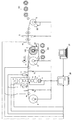
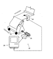
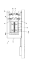
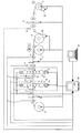
- FIG. 1 is a schematic view of a cold rolled material installation according to a first embodiment of the present invention.
- the cold rolled material equipment mainly includes a reversible cold rolling mill 1, an unwinding device 2 for unwinding a strip of the carry-in coil 101, and the cold rolling mill 1.
- the winding and unwinding device 3 first winding and unwinding device
- the winding and unwinding device 4 disposed on the exit side of the first pass of the cold rolling mill 1 (A second winding and unwinding device)
- a joining device 5 disposed downstream of the unwinding device 2 and forming a buildup coil 102 from a plurality of carry-in coils 101
- a coil buildup for winding up and winding the buildup coil 102
- cutting device 7 for separating the strip of buildup coil 102 in the final pass to form unloading coil 103
- cold rolling mill 1 unwinding device 2
- winding unwinding device 3 4
- bonding device 5 winding and unwinding device 6 (coil build And
- the reversible cold rolling machine 1 includes, for example, upper and lower work rolls 11 and 11 which are brought into direct contact with rolling material for rolling, upper and lower intermediate rolls 12 and 12 which support these work rolls in the vertical direction, and these intermediate rolls It is a six-stage UC mill provided with upper and lower reinforcing rolls 13, 13 for supporting 12, 12 in the vertical direction.
- a hydraulic pressure reduction device 14 is provided below the lower reinforcement roll 13 so that the hydraulic pressure reduction device 14 moves the bearing of the lower reinforcement roll 13 up and down according to the command so that a predetermined reduction amount can be obtained. Press down the strip.
- a load meter 15 is provided on the upper portion of the upper reinforcing roll 13 and adjusts the amount of pressure reduction of the roll according to the load change detected by the load meter 15. This series of operations is called reduction control.
- the thickness gauge 16a, the plate speed gauge 17a, and the shape gauge 18a are on the entrance side of the first pass of the cold rolling mill 1, and the thickness gauge 16b is on the exit side of the first pass of the cold rolling mill 1.
- a plate speed meter 17 b and a shape meter 18 b are provided and used for plate thickness control and shape control, and pressure reduction control is performed based on the results of these controls.
- the unwinding device 2 has a collapsible reel having an expanding and contracting function, sets the feed-in coil 101, and unwinds the strip. Further, the unwinding device 2 has a coil centering mechanism 22 (described later).
- the winding and unwinding device 3 and the winding and unwinding device 4 change the rolling direction by repeating the winding and unwinding of the rolling material between the winding and unwinding device 3 and the winding and unwinding device 4. Perform cold rolling of the pass. Further, the winding and unwinding device 3 and the winding and unwinding device 4 both have collapsible reels having an expansion / contraction function, and carry out the discharge coil 103 formed by division.
- the joining device 5 joins the strip trailing end of the first carry-in coil 101a which has been unwound and the strip end of the second carry-in coil 101b which is subsequently unwound from the unwinding device 2, and so on.
- the strip tail end of the carry-in coil 101 b and the tip end of the strip of the third carry-in coil 101 c are joined to form a buildup coil 102.
- the winding and unwinding device 6 (for coil buildup) sequentially winds up the strips of the buildup coil 102 joined by the joining device 5 and unwinds the strip of the buildup coil 102 in a first pass.
- the winding and unwinding device 6 has a solid type reel without an expansion and contraction function.
- the winding and unwinding device 6 does not necessarily have to have a solid type reel, and may have a collapsing type reel.
- the winding and unwinding device 6 has a coil centering mechanism 23 (described later).
- the cutting device 7 comprises a cutting device 7a and a cutting device 7b.
- the cutting device 7a is disposed between the cold rolling mill 1 and the winding and unwinding device 3, and cuts the strip of the buildup coil 102 in a pass where the final pass is completed by the winding and unwinding device 3.
- the cutting device 7 b is disposed between the cold rolling mill 1 and the winding and unwinding device 4, and cuts off the strip of the buildup coil 102 in a pass which is completed by the winding and unwinding device 4.
- the cutting devices 7a and 7b have a swing mechanism (not shown).
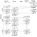
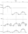
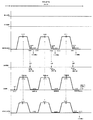
- FIGS. 5 to 7 are timetables of the respective devices 1 to 7 corresponding to the control flow, and the same step numbers are assigned to portions corresponding to the processing steps of the control flow.
- the control device 20 controls the unwinding device 2 as follows.
- the unwinding device 2 unrolls the strip of the first carry-in coil 101a at a speed equal to or approximately the speed of the board (S0201 for convenience).
- the strip of the first loading coil 101a is gripped by the winding and unwinding device 6, the unwinding device 2 unrolls the strip of the first loading coil 101a at a steady speed (S0202).
- the steady-state speed is the maximum speed at which the capability of the unwinding device 2 can be maximized (hereinafter, the steady-state speeds in the winding and unwinding devices 3, 4 and 6 are the same).
- the unwinding device 2 stops when the strip trailing end of the first carry-in coil 101a is unwound (S0203), and when the second carry-in coil 101b is carried in and mounted, the stripper of the second carry-in coil 101b is joined at a passing plate speed.
- the unwinding device 2 stops the unwinding (S0204).
- the unwinding device 2 unwinds the strip of the remaining second loading coil 101b at a steady speed (S0205).
- the unwinding device 2 stops when the strip trailing end of the second carry-in coil 101b is unwound (S0206), carries in the third carry-in coil 101c and mounts it, and joins the strip of the third carry-in coil 101c at the sheet passing speed.
- the unwinding device 2 stops unwinding (S0207).
- the unwinding device 2 subsequently unwinds the strip of the remaining third loading coil 101c at a steady speed (S0208).
- the unwinding device 2 is stopped (S0209).
- the control device 20 controls the bonding device 5 as follows.
- the joining device 5 includes the first carry-in coil 101a and the second carry-in coil. It joins with 101b (S0501).
- the bonding device 5 performs the second carry-in coil.
- the 101b and the third carry-in coil 101c are joined (S0502).
- the control device 20 controls the winding and unwinding device 6 (for coil buildup) as follows.
- the take-up and unwinding device 6 grips the leading end of the strip of the first delivery coil 101a (S0601) .
- the take-up and unwinding device 6 takes up the strip of the first carry-in coil 101a at a steady speed (S0602), and when the strip tail end of the first carry-in coil 101a reaches the joining device 5, the take-up and take-out device 6 takes It decelerates and stops winding (S0603).
- the take-up and unwinding device 6 winds the strip of the remaining first carry-in coil 101a at a steady speed, and subsequently, the joined second carry-in The strip of the coil 101b is wound (S0604).
- the take-up and unwinding device 6 decelerates and stops the take-up (S0605).
- the take-up and unwinding device 6 winds up the strip of the remaining second carry-in coil 101b at a steady speed, and subsequently, the joined third Take up the strip of the carry-in coil (S0606).
- the winding and unwinding device 6 stops when all the strips of the third carry-in coil 101c are wound (S0607).
- the buildup coil 102 is formed of the three coils 101a, 101b, and 101c (S0608).
- the outer diameter of the buildup coil 102 is set to ⁇ 3000 or less.
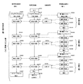
- the control device 20 controls the cold rolling mill 1 as follows. Before the start of rolling in the first pass, the leading end of the strip of the buildup coil 102 is fed from the winding and unwinding device 6 to the winding and unwinding device 4 and gripped by the winding and unwinding device 4. 1 is under pressure control (S1101). When the preparation for rolling is completed, the cold rolling mill 1 accelerates to the steady rolling speed, and performs the first pass rolling at the steady rolling speed (S1102).
- the cold rolling mill 1 decelerates, and the strip tail end of the buildup coil 102 immediately before the cold rolling mill 1 When it arrives, the cold rolling mill 1 stops rolling (S1103), and ends rolling of the first pass (S1111).
- the strip tail end of the buildup coil 102 stopped immediately before the cold rolling mill 1 at the end of the first pass is fed to the take-up and unwinding device 3 in the reverse direction to the first pass,
- the cold rolling mill 1 is controlled for reduction (S2101).
- the cold rolling mill 1 accelerates to the steady rolling speed in the direction opposite to the first pass, and performs rolling in the second pass at the steady rolling speed (S2102).
- the cold rolling mill 1 decelerates and stops (S2103), and the second pass The rolling is finished (S2104).
- the cold rolling mill 1 is controlled to reduce the thickness so as to obtain a desired plate thickness (S3101).
- the cold rolling mill 1 accelerates to the steady rolling speed in the direction opposite to the second pass, and performs rolling in the third pass at the steady rolling speed (S3102).
- the cold rolling mill 1 decelerates and stops (S3103), and the third pass The rolling is finished (S3104).
- the steady rolling speed is the maximum speed at which the ability of the cold rolling mill can be maximized in obtaining a desired plate thickness in each pass.
- the steady rolling speed in a cold reversible rolling facility is generally in the range of 400 mpm to 1400 mpm.
- the control device 20 controls the winding and unwinding device 6 (for coil buildup) as follows.
- the winding and unwinding device 6 unwinds the strip of the buildup coil 102 formed in the coil buildup process to the winding and unwinding device 4 at a sheet passing speed (S1601), and when the rolling preparation for the first pass is completed,
- the winding and unwinding device 6 unwinds the strip of the buildup coil 102 (S1602) in accordance with the rolling speed of the cold rolling mill 1 which performs rolling at a steady rolling speed (S1603).
- the control device 20 controls the winding and unwinding device 3 (first winding and unwinding device) as follows.
- the take-up and unwinding device 3 Grip the end (S2301).
- the winding and unwinding device 3 winds up the strip of the buildup coil 102 (S2302) in accordance with the rolling speed of the cold rolling mill 1 which performs rolling at a steady rolling speed (S2302), and decelerates in accordance with the end of second pass rolling. Stop (S2303).
- the winding and unwinding device 3 unwinds the strip of the buildup coil 102 in accordance with the rolling speed of the cold rolling mill 1 which performs rolling at a steady rolling speed (S3301), and in accordance with the completion of the third pass rolling.
- the motor decelerates and stops (S3302).
- the control device 20 controls the winding and unwinding device 4 (second winding and unwinding device) as follows.
- the take-up and unwinding device 4 grips the strip end (S1401).
- the winding and unwinding device 4 winds up the strip of the buildup coil 102 in accordance with the rolling speed of the cold rolling mill 1 which performs rolling at a steady rolling speed (S1402), and decelerates in accordance with the completion of the first pass rolling. Stop (S1403).
- the winding and unwinding device 4 unwinds the strip of the buildup coil 102 at a passing speed to the winding and unwinding device 3 in the direction opposite to the first pass (S2401), and the rolling preparation of the second pass is completed.
- the winding and unwinding device 4 unwinds the strip of the buildup coil 102 according to the rolling speed of the cold rolling mill 1 which performs rolling at a steady rolling speed (S2402), according to the end of the second pass rolling It decelerates and stops (S2403).
- the winding and unwinding device 4 winds up the strip of the buildup coil 102 in accordance with the rolling speed of the third pass of the cold rolling mill 1 which performs rolling at a steady rolling speed in the opposite direction to the second pass. S3401), decelerating and stopping at the end of the third pass rolling (S3402).
- the buildup coil is divided into three discharge coils 103a to 103c.
- the first to third passes of the coil build-up step and the reversible rolling step described above are steps substantially common to the second prior art (described later), while the fourth pass (final pass) of the reversible rolling step and the dividing step Is a characteristic process of this embodiment.
- the control device 20 controls the cold rolling mill 1 as follows. After the completion of the third pass rolling, before the start of the fourth pass rolling, the cold rolling mill 1 is controlled so as to obtain a desired plate thickness (S4101). When the preparation for rolling is completed, the cold rolling mill 1 accelerates to the steady rolling speed in the direction opposite to the third pass, and performs rolling in the fourth pass (final pass) at the steady rolling speed (S4102). The cold rolling mill 1 decelerates in accordance with the procedure in which the strip of the buildup coil 102 is divided by the cutting device 7a and the first unloading coil 103a is unloaded from the winding and unwinding device 3, and at a low speed (for example, 2 mpm) The rolling is performed (S4103).
- the cold rolling mill 1 accelerates again to the steady rolling speed, and the steady rolling speed is maintained for the remaining strip of the final pass of the buildup coil 102.
- Rolling is performed (S4104), the cold rolling mill 1 is decelerated in accordance with the procedure in which the strip of the buildup coil 102 is divided by the cutting device 7a and the second carry-out coil 103b is carried out from the winding and unwinding device 3. And rolling at a low speed (for example, 2 mpm) (S4105).
- the cold rolling mill 1 accelerates again to the steady rolling speed, and the steady rolling speed for the remaining strip of the final pass of the buildup coil 102 is increased.
- Rolling is performed (S4106), the cold rolling mill 1 is decelerated in accordance with the procedure in which the strip of the buildup coil 102 is divided by the cutting device 7a and the third unloading coil 103c is unloaded by the winding and unwinding device 3. And rolling at a low speed (for example, 2 mpm) (S4107).
- the cold rolling mill 1 stops rolling (S4108) and finishes rolling of the fourth pass (final pass) (S4109) ).
- the control device 20 controls the winding and unwinding device 3 (first winding and unwinding device) as follows.
- the winding and unwinding device 3 winds up the strip of the buildup coil 102 in accordance with the rolling speed of the fourth pass (final pass) of the cold rolling mill 1 which performs rolling at a steady rolling speed (S4301).
- the winding and unwinding device 3 winds up the strip of the buildup coil 102 in accordance with the rolling speed of the cold rolling mill 1 that performs rolling at low speed (for example, 2 mpm) according to the procedure of dividing and winding up (S4302 And after the first unloading coil 103a is divided, the winding and unwinding device 3 winds up the remaining strip at high speed (S4303), and after completion of winding, the winding and unwinding device 3 extracts and unloads the first unloading coil 103a. (S4304).
- the tip of the strip to be fed out (the tip of the second carry-in coil 103b) is wound with a belt wrapper (S4305), and when the winding preparation is completed, the fourth pass of the cold rolling mill 1 which performs rolling at a steady rolling speed (final
- the winding and unwinding device 3 winds the strip of the buildup coil 102 at a low speed (for example, 2 mpm) according to the procedure of dividing the buildup coil 102 according to the rolling speed of a predetermined length (S4306).
- the winding and unwinding device 3 winds up the strip of the buildup coil 102 in accordance with the rolling speed of the cold rolling mill 1 (S4307), and after the second unloading coil 103b is divided, the winding and unwinding device 3 holds the rest.
- the strip is wound at high speed (S4308), and after completion of the winding, the winding and unwinding device 3 extracts and carries out the second unloading coil 103b (S4309).
- the tip of the strip to be fed out (the tip of the third carry-in coil 103c) is wound with a belt wrapper (S4310), and when the winding preparation is completed, the fourth pass of the cold rolling mill 1 which performs rolling at a steady rolling speed (final
- the winding and unwinding device 3 winds the strip of the buildup coil 102 at a low speed (for example, 2 mpm) according to the procedure of dividing the buildup coil 102 by winding the strip for a predetermined length (S4311).
- the strip of the buildup coil 102 is wound according to the rolling speed of the cold rolling mill 1 (S4312), and after the third unloading coil 103b is divided, the winding and unwinding device 3 winds the remaining strip at high speed ( S4313) After completion of the winding, the winding and unwinding device 3 extracts and carries out the third unloading coil 103c (S4314).
- the belt wrapper is used in the winding and unwinding device 3 If it is not equipped (not shown), the tip of the strip is gripped.
- the control device 20 controls the winding and unwinding device 4 (second winding and unwinding device) as follows.
- the winding and unwinding device 4 unwinds the strip of the buildup coil 102 (S4401) in accordance with the rolling speed of the fourth pass (final pass) of the cold rolling mill 1 which performs rolling at a steady rolling speed (S4401)
- the winding and unwinding device 4 unrolls the strip of the buildup coil 102 in accordance with the rolling speed of the cold rolling mill 1 which performs rolling at low speed (for example, 2 mpm) according to the dividing procedure. ).
- the winding and unwinding device 4 unwinds the strip of the buildup coil 102 (S4403) and breaks it a predetermined length according to the rolling speed of the cold rolling mill 1 which performs rolling at steady rolling speed again (S4403)
- the winding and unwinding device 4 unwinds the strip of the buildup coil 102 in accordance with the rolling speed of the cold rolling mill 1 which performs rolling at a low speed (for example, 2 mpm) according to the procedure to be performed (S4404).
- the winding and unwinding device 4 unwinds the strip of the buildup coil 102 according to the rolling speed of the cold rolling mill 1 which performs rolling at the steady rolling speed again (S4405), and when the predetermined length is unwound
- the winding and unwinding device 4 unwinds the strip of the buildup coil 102 in accordance with the rolling speed of the cold rolling mill 1 which performs rolling at a low speed (for example, 2 mpm) according to the procedure to be performed (S4406).
- the winding and unwinding device 4 winds up the remaining strip, extracts the off gauge coil 103d, and carries it out (S4407).
- the control device 20 controls the cutting device 7a as follows.
- the control device 20 calculates each cutting position from the coil outer diameter and the reel rotation number of each of the winding and unwinding devices 3 and 4, and the cutting device 7a cuts the first unloading coil 103a from the strip of the buildup coil 102 at the cutting position.
- the second unloading coil 103b is divided from the remaining strips at the next cutting position (S4702), and the third unloading coil 103c is separated from the remaining strips at the next cutting position (S4703).
- control device 20 calculates the cutting position based on the coil outer diameter and the reel rotation number, but drilling is performed at the cutting position, and a cutting position detection device (not shown) detects the cutting position. There is also a way. There is also a method of grasping the cutting position by calculating the distance using the distance measuring function of the plate speed meter.
- the strip of the first carry-in coil 101a is unwound at a speed of about the sheet passing speed (hereinafter referred to as sheet passing speed for convenience) and wound.
- sheet passing speed the sheet passing speed
- the strip of the first carry-in coil 101a is unwound from the take-out device 2 at a steady speed and taken up and taken out.
- the steady state speed is the maximum speed at which the capabilities of the unwinding device 2 and the winding and unwinding device 6 can be maximized (hereinafter, the same as the steady state velocity in the winding and unwinding devices 3 and 4) .
- the remaining strip of the first carry-in coil 101a is taken up by the take-up and unwinding device 6, and subsequently, the joined second carry-in coil 101b is The strip is unwound from the unwinding device 2 at a steady speed and taken up by the take-up unwinding device 6 (S0205 ⁇ S0604).
- the strip tail end of the second carry-in coil 101b and the tip end of the strip of the third carry-in coil 101c are joined by the joining device 5 (S0502).
- the remaining strip of the second carry-in coil 101b is taken up by the winding and unwinding device 6, and subsequently, the joined third carry-in coil 101b is The strip is unwound from the unwinding device 2 at a steady speed and taken up by the take-up unwinding device 4 (S0208 ⁇ S0606).
- the buildup coil 102 is formed in the winding and unwinding device 6 (S0608).
- the outer diameter of the buildup coil 102 is set to ⁇ 3000 or less.
- the strip of the buildup coil 102 is unwound from the winding and unwinding device 6 at a sheet passing speed, and the tip of the strip is gripped by the winding and unwinding device 4 and wound up several turns. Thereafter, the cold rolling mill 1 is subjected to pressure reduction control (S1601 ⁇ S1401 ⁇ S1101).
- the cold rolling mill 1 is feedback-controlled so as to become the command rolling speed. Further, the winding and unwinding device 6 is subjected to tension feedback control so that the strip tension between the winding and unwinding device 6 and the cold rolling mill 1 becomes a predetermined value. Further, the winding and unwinding device 4 is also subjected to tension feedback control so that the strip tension between the winding and unwinding device 4 and the cold rolling mill 1 becomes a predetermined value.
- the strip of the buildup coil 102 is rolled at a steady rolling speed by the cold rolling mill 1 and unwound from the winding and unwinding device 6 according to the rolling speed of the cold rolling mill 1 and wound onto the winding and unwinding device 4 It is taken (S1602 ⁇ S1102 ⁇ S1402).
- the cold rolling mill 1 is stopped and the first pass is finished, and the winding and unwinding device 4 is synchronized with the stop of the cold rolling mill 1.
- the device 6 is stopped (S1103 ⁇ S1603 ⁇ S1403 ⁇ S1104).
- the rolling direction is switched in the reverse direction to start the second pass.
- the strip of the buildup coil 102 is unwound from the winding and unwinding device 4 at a sheet passing speed, and the trailing end of the strip (the second pass direction strip tip) is gripped by the winding and unwinding device 3 and wound by several turns. To be taken. Thereafter, the cold rolling mill 1 is subjected to pressure reduction control (S2401 ⁇ S2301 ⁇ S2101).
- the strip of the buildup coil 102 is rolled at a steady rolling speed by the cold rolling mill 1 and unwound from the winding and unwinding device 4 according to the rolling speed of the cold rolling mill 1 Then, the sheet is taken up by the take-up unwinding device 3 (S2402-> S2102-> S2302).
- the strip of the buildup coil 102 is unrolled by a predetermined length, the cold rolling mill 1 is stopped and the second pass is finished, and the winding and unwinding device 3 is taken into consideration when the cold rolling mill 1 is stopped.
- the device 4 is stopped (S2103 ⁇ S2403 ⁇ S2303 ⁇ S2104).
- the rolling direction is switched in the reverse direction to start the third pass.
- the cold rolling mill 1 is controlled for reduction, and the strip of the buildup coil 102 is controlled by the cold rolling mill 1
- the sheet is rolled at a steady rolling speed, unwound from the winding and unwinding device 3 according to the rolling speed of the cold rolling mill 1, and wound up by the winding and unwinding device 4 (S3101 ⁇ S3102 ⁇ S3301 ⁇ S3401).
- the cold rolling mill 1 is stopped and the third pass is finished, and in accordance with the stop of the cold rolling mill 1, the winding and unwinding device 3, the winding and unwinding The device 4 is stopped (S3103 ⁇ S3302 ⁇ S3402 ⁇ S3104).
- the cold rolling mill 1 is controlled for reduction, and the strip of the buildup coil 102 is controlled by the cold rolling mill 1
- the sheet is rolled at a steady rolling speed, unwound from the winding and unwinding device 4 according to the rolling speed of the cold rolling mill 1, and wound up by the winding and unwinding device 3 (S4101 ⁇ S4102 ⁇ S4301 ⁇ S4401).
- the cold rolling mill 1 decelerates to a predetermined low speed, and the strip of the buildup coil 102 is slowed by the cold rolling mill 1.
- the sheet is rolled (for example, 2 mpm), unwound from the winding and unwinding device 4 according to the rolling speed of the cold rolling mill 1, and wound around the winding and unwinding device 3 (S4103 ⁇ S4302 ⁇ S4402).
- the strip of the buildup coil 102 is separated by the cutting device 7a in the strip cutting position, and the remaining strip of the separated first unloading coil 103a is wound up.
- the film is taken up by the unwinding device 3 at high speed.
- the winding and unwinding device 3 is stopped, and the first unloading coil 103a is removed from the winding and unwinding device 3 and carried out (S4701 ⁇ S4303 ⁇ S4304).
- a collapsible reel is applied to the winding and unwinding device 3.
- the remaining strip of the divided build-up coil 102 is rolled at a low speed by the cold rolling mill 1 and wound according to the rolling speed of the cold rolling mill 1 It is unwound from the unwinding device 4.
- the tip of the delivered strip (corresponding to the second carry-in coil 103b) is taken up by the belt wrapper of the take-up and take-out device 3 (S4305).
- the remaining strip of the buildup coil 102 is rolled at a steady rolling speed by the cold rolling mill 1 and wound according to the rolling speed of the cold rolling mill 1
- the film is unwound from the unwinding device 4 and taken up by the winding and unwinding device 3 (S4104 ⁇ S4403 ⁇ S4306).
- the cold rolling mill 1 decelerates to a predetermined low speed, and the strip of the buildup coil 102 is low speed by the cold rolling mill 1 , Rolled according to the rolling speed of the cold rolling mill 1 and taken up by the take-out device 3 (S4105 ⁇ S4404 ⁇ S4307).
- the strip of the buildup coil 102 is divided by the cutting device 7a in the strip cutting position, and the remaining strip of the divided second unloading coil 103b is wounded.
- the film is taken up by the unwinding device 3 at high speed.
- the winding and unwinding device 3 is stopped, and the second unloading coil 103b is extracted from the winding and unwinding device 3 and carried out (S4702 ⁇ S4308 ⁇ S4309).
- the remaining strip of the divided build-up coil 102 is rolled at a low speed by the cold rolling mill 1 and wound according to the rolling speed of the cold rolling mill 1 It is unwound from the unwinding device 4.
- the tip of the strip (corresponding to the third carry-in coil 103c) that has been fed out is wound up by the belt wrapper of the winding and unwinding device 3 (S4310).
- the remaining strip of the buildup coil 102 is rolled at a steady rolling speed by the cold rolling mill 1 and wound according to the rolling speed of the cold rolling mill 1
- the film is unwound from the unwinding device 4 and taken up by the winding and unwinding device 3 (S4106 ⁇ S4405 ⁇ S4311).
- the cold rolling mill 1 is decelerated to a predetermined low speed, and the strip of the buildup coil 102 is low speed by the cold rolling mill 1. And rolled out from the winding and unwinding device 4 according to the rolling speed of the cold rolling mill 1 and taken up by the winding and unwinding device 3 (S4107 ⁇ S4406 ⁇ S4312).
- the strip of the buildup coil 102 is separated by the cutting device 7a in the strip cutting position, and the remaining strip of the separated third unloading coil 103c is wound up.
- the film is taken up by the unwinding device 3 at high speed.
- the winding and unwinding device 3 is stopped, and the third unloading coil 103c is extracted from the winding and unwinding device 3 and carried out (S4703 ⁇ S4313 ⁇ S4314).
- the cold rolling mill 1 stops rolling and ends the fourth pass, and the remaining strip of the divided buildup coil 102 is wound by the winding and unwinding device 4.
- the wound off-gauge coil 103d is extracted from the winding and unwinding device 4 and carried out (S4108 ⁇ S4109 ⁇ S4407). As described above, a collapsible reel is applied to the winding and unwinding device 4.
- the unloading coils 103a to 103c are unloaded from the winding and unwinding device 3, and the off gauge coil 103d is unloaded from the winding and unwinding device 4.
- the strip of the buildup coil 102 is divided by the cutting device 7b, the unloading coils 103a to 103c are extracted from the winding and unwinding apparatus 4 and unloaded, and the off gauge coil 103d is wound. It is carried out of the unwinding device 3.
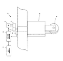
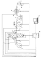
- FIG. 8 is a schematic view of a cold rolled material installation according to the first prior art.
- the same reference numerals as in FIG. 1 denote the same parts.
- the cold rolled material equipment (RCM equipment) according to the first prior art mainly unwinds the strip in the reversible cold rolling mill 1 and the cold rolling mill 1 in the first pass.
- the control device 20 controls the device 4, the cold rolling mill 1, the unwinding device 2, and the winding and unwinding devices 3 and 4.
- the carry-in coil 101a is carried into the unwinding device 2, the end of the strip is passed through, is gripped by the take-up and take-out device 4, and is further wound for several turns, completing the preparation for rolling such as tension application and pressure reduction.
- the cold rolling mill 1 starts rolling of the first pass. When the strip tail end comes just before the cold rolling mill 1, the rolling of the first pass is finished.
- the strip tip is passed in the opposite direction to the first pass, and the strip tip is gripped by the take-up and unwinding device 3 and is further wound for several turns to complete the preparation for rolling such as application of tension and pressure.
- the rolling of the second pass is started by the cold rolling mill 1.
- the second pass rolling is finished in a state in which the winding and unwinding device 4 grips several turns of the strip end.
- rolling of the third pass is started by the cold rolling mill 1.
- the third pass rolling is finished in a state in which the winding and unwinding device 3 grips several turns of the strip end.
- the cold rolling mill 1 After completion of the fourth pass tensioning and rolling preparation such as reduction, the cold rolling mill 1 starts rolling of the fourth pass.
- the unloading coil 103a after rolling in the fourth pass is taken up by the take-up unwinding device 3, taken out, and taken out. As described above, a collapsible reel is applied to the winding and unwinding device 3.
- the carry-in coil 101b is carried into the unwinding device 2
- the carry-out coil 103b is carried out from the winding and unwinding device 3
- the carry-in coil 101c is carried into the unwinding device 2
- the carry-out coil 103c is a winding and unwinding device It is carried out from 3.
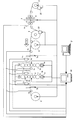
- FIG. 9 is a schematic view of a cold rolled material installation according to the second prior art.
- the same reference numerals as in FIG. 1 denote the same parts.
- the cold rolled material equipment mainly includes a reversible cold rolling mill 1, an unwinding device 2 for unwinding a strip of the carry-in coil 101, and a cold rolling mill.
- the winding and unwinding device 3A first winding and unwinding device
- the winding and unwinding device 3A second winding and unwinding device
- a joining device 5 for forming a buildup coil 102 from a plurality of carry-in coils 101
- a coil buildup winding and unwinding device 6A for forming a buildup coil
- a cutting device 7 for dividing the strip of the buildup coil 102 to form an unloading coil 103
- Solid reels are applied to the winding and unwinding devices 3A, 4A and 6A, and collapsing reels are applied to the unwinding device 2 and the winding devices 112 and 113.
- the carry-in coil 101a is carried in and taken out of the unwinding device 2, and the tip of the strip is gripped and taken up by the coil build-up take-up and take-out device 6A.
- the incoming coil 101b is carried into the unwinding device 2 and unwound until the tip of the strip is delivered to the joining position of the joining device 5, It stops and the strip tail end of the 1st carrying-in coil 101a and the strip tip of the 2nd carrying-in coil 101b are joined by the joining apparatus 5.
- the joined strips are taken up by a coil build-up take-up and take-out device 6A. .
- the strip tail end of the second carry-in coil 101b and the tip end of the strip of the third carry-in coil 101c are joined by the joining apparatus 5, and the joined strip is wound on the coil buildup take-up and unwinder 6A.
- the buildup coil 102 is formed in the coil buildup take-up and unwinding device 6A.
- the strip of the buildup coil 102 is unrolled from the coil buildup winding and unwinding device 6A, passed through the plate, gripped by the winding and unwinding device 4A, and after control of reduction, the cold rolling mill 1 performs the first pass Rolling is performed. Thereafter, the second to third passes of reversible rolling are performed between the winding and unwinding device 3A and the winding and unwinding device 4A.
- the remaining strips are also separated by the cutting device 7a, and the separated discharge coils 103b and 103c are sequentially extracted from the winding device 112 and discharged. As described above, a collapsible reel is applied to the winding and unwinding device 112.
- the cutting device 7 b is disposed between the cold rolling mill 1 and the winding device 113, and cuts off the strip of the buildup coil 102 in a pass where the winding device 113 completes the winding.
- the cold rolled material facility according to the second prior art assumes a relatively large scale production facility with an annual production volume of 800,000 tons or more. There is.
- the cold-rolled material equipment according to the second prior art has a joining device 5, a cutting device 7, a winding and unwinding device 6A (for coil buildup), and winding compared to the cold-rolled material equipment according to the first prior art.
- the configuration of the removing devices 112, 113 is increased, and the initial cost is increased.
- the cold-rolled material equipment related to the second prior art assumes relatively large-scale production equipment with an annual production volume of 800,000 tons or more, and in order to give priority to lowering the off-gauge rate and improving production efficiency, the initial cost is It does not matter even if it is somewhat bulky.
- the cold rolled material equipment according to the second prior art is applied to small- and medium-sized production equipment with an annual production volume of about 300,000 to 600,000 tons, the problem of initial cost becomes significant, and the cost effectiveness is improved. There was a problem.
- the unrolled portion is generated only at the strip tip of the carry-out coil 103a and at the strip tail end of the carry-out coil 103c, it is possible to significantly reduce the off gauge ratio. Furthermore, the portion of unsteady rolling speed decreases, and the plate thickness accuracy is improved. That is, high efficiency and high yield equivalent to those of the second prior art can be maintained.
- the outer diameter of the buildup coil 102 is set to ⁇ 3000 or less. Further, the strip tension at the time of the large diameter of the buildup coil 102 is set to be gradually lower than that at the time of the small diameter.
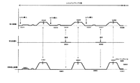
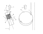
- FIG. 10 is a view showing tension control at the time of winding up of the buildup coil 102. As shown in FIG. When the outer diameter of the buildup coil 102 is less than ⁇ 1500, steady-state predetermined tension is applied, but when the outer diameter of the buildup coil 102 is ⁇ 1500 or more, it is set to gradually decrease as the outer diameter increases. ing.
- the tightening force acting on the buildup coil 102 can be limited, and the enlargement of the winding and unwinding devices 3, 4 and 6 due to the enlargement of the outer diameter of the buildup coil 102 can be suppressed.
- the take-up and unwinding devices 3 and 4 of the present embodiment apply collapsible reels. Can.
- the cutting devices 7a and 7b have a swing mechanism (not shown).
- Cutting equipment in cold tandem rolling equipment with annual production volume of 1,000,000 tons or more is generally divided into coils between runs while continuing rolling, and after division, two or more winding devices called carrousel reels Was wound alternately with the take-up device. Since the speed at the time of coil division is reduced only to about 100 mpm to 300 mpm in order to suppress the reduction of the annual production amount and the deterioration of the off gauge rate, the cutting device that divides the coil between running while continuing the conventional rolling However, there has been a problem that the initial cost increases if a conventional cutting device is adopted in a small-to-medium-sized production facility with an annual production volume of about 300,000 to 600,000 tons.
- the rolling speed at the time of dividing the buildup coil 102 is low (for example, 2 mpm). Therefore, a cutting device having a relatively inexpensive swing mechanism can be applied instead of the conventional expensive running-running cutting device, and the initial cost can be reduced.
- the cutting device 7a having the swing mechanism can cut the strip without stopping the rolling as described in the operation of the fourth pass.
- the rolling speed at the time of dividing the buildup coil 102 by the cutting device 7a is low (for example, 2 mpm).
- the carry-out coil 103 is divided by the cutting device 7a, taken up by the take-up and take-out device 3 at high speed, and then taken out and carried out. This series of operations is performed, for example, in about 150 seconds or less.
- the tip of the buildup coil 102 strip after division is cold from the cutting position of the cutting device 7a to the winding and unwinding device 3,
- the arrival time is 150 seconds. That is, before preparation for winding up the second carry-in coil 103b, the first carry-out coil 103a is carried out.
- the carry-out coil 103 is extracted and carried out, and thereafter the next carry-out coil 103 is wound.
- the large-sized winding and unwinding device 3A to which a solid block type reel is applied is compared with the compact and winding and unwinding device 3 to which a collapsible reel is applied. It can be replaced so that the winding device 112 is not necessary.
- the winding and unwinding device 4A can be replaced with the winding and unwinding device 4, and as a result, the winding device 113 becomes unnecessary.
- the upsizing of the winding and unwinding devices 3, 4 and 6 can be suppressed, and the winding devices 112 and 113 which are essential in the second prior art become unnecessary, whereby the equipment configuration can be simplified, As a result, the initial cost can be reduced.
- a relatively inexpensive bonding apparatus of mash seam welding method is used as the bonding apparatus 5. This can reduce the initial cost.
- the stop marks may be transferred onto the strip surface at equal intervals at the rotational pitch of the work roll during post-rolling. If the stop mark is generated in the first pass, the stop mark may not be noticeable to a level that can not be visually observed by continuing rolling a plurality of times. However, when the stop mark is generated in the final pass, the quality of surface gloss is impaired, and there is a problem that a material of strict quality becomes a defective product.
- the cold-rolled material installation according to the present embodiment can be realized by improving the cold-rolled material installation according to the first prior art.
- the cold-rolled material equipment according to the first prior art has a configuration (reversible rolling line) necessary for the reversible rolling process, and the cold-rolled material equipment according to the present embodiment has a coil build in the configuration of the reversible rolling line.
- the configuration (build-up line) required for the up process is added.
- the cold rolling material equipment according to the first prior art mainly includes the cold rolling mill 1, the unwinding device 2, the winding and unwinding devices 3 and 4, and the control device 20 for controlling them. Is equipped.
- the winding and unwinding devices 3 and 4 of the first prior art can be used.
- the joining device 5 of this embodiment, the winding and unwinding device (for coil buildup) 6 and the cutting devices 7a and 7b may be newly added.
- the cold-rolled material equipment according to the present embodiment can be realized while effectively using the existing equipment (the first prior art), so the initial cost can be suppressed.
- the winding method is classified as follows according to the thickness of the strip to be wound.
- the gripper method is applied, and when the thickness of the strip is less than 4 mm, the belt wrapper method is applied. If the thickness of the strip is wide (over 4 mm), both methods may be used in combination.
- the gripper method may be applied even when the thickness of the strip is less than 4 mm from the viewpoint of initial cost-effectiveness.
- a cheaper gripper reel is preferably applied to the winding and unwinding device (for coil build-up) 6.
- the gripper reel is applied to the winding and unwinding device 6, a bent portion is generated at the strip tail end (first pass direction) of the buildup coil 102. If there is a bent portion, a problem occurs when the winding and unwinding device 3 grips the strip end in the second pass of the reversible rolling process (S2301). That is, the winding and unwinding device 3 can not grip (or belt wrap) the strip end.
- the cold rolling mill 1 has, for example, upper and lower work rolls 11, 11 for rolling in direct contact with rolling material, upper and lower intermediate rolls 12, 12 for supporting the work rolls in the vertical direction, and these intermediate rolls 12, 12 6-stage UC mill provided with upper and lower reinforcing rolls 13, 13 for supporting the above in the vertical direction.
- a hydraulic pressure reduction device 14 is provided below the lower reinforcing roll 13, and the hydraulic pressure reduction device 14 moves a bearing of the lower reinforcing roll 13 up and down based on a command from the control device 20 to obtain a predetermined pressure reduction. Press down the strip to volume.
- a load meter 15 is provided on the upper portion of the upper reinforcing roll 13, and the information detected by the load meter 15 is output to the control device 20.
- the thickness gauge 16a, the plate speedometer 17a, and the shape gauge 18a are on the entrance side of the first pass of the cold rolling mill 1, and the thickness gauge 16b, the plate speed on the exit side of the first pass of the cold rolling mill 1.
- a total 17 b and a shape meter 18 b are provided, and the information detected by each is output to the control device 20.
- the thickness gauge 16 may be a laser Doppler type speedometer, or the plate speed may be detected by the rotational speed of a differential roller or a shape detector.
- the thickness control at the time of steady rolling will be described.
- BISRA-AGC control and monitor AGC control are used in combination as appropriate.
- BISRA-AGC control detects a change in plate thickness on the entry side of the cold rolling mill 1 as a change in rolling load by the load meter 15, and adjusts the rolling reduction amount according to the detected load change It is.
- the monitor AGC control detects a change in thickness on the outlet side of the cold rolling mill 1 from the thickness gauge 16b on the outlet side, feeds back the detected thickness change, and adjusts the amount of reduction by proportional integral control It is.
- the thickness gauge 16b is provided several meters away from the cold rolling mill 1, and a time delay occurs in the detection value of the thickness gauge 16b, but in steady rolling (for example, 1000 mpm), almost no influence is exerted. Absent. However, when applied at low speed rolling (for example, 2 mpm), due to the influence of time delay, appropriate information can not be obtained, and the thickness control accuracy is reduced.
- MF-AGC control is applied to low speed rolling.
- the MF-AGC control performs the following control.
- the detection value of the thickness gauge 16a on the entry side is tracked to just below the rolling stand to be controlled.
- the respective plate speeds are detected using the plate speed meters 17a and 17b on the inlet and outlet sides.
- the control device 20 multiplies the inlet side plate thickness by the inlet side outlet side plate speed ratio to estimate the outlet side plate thickness, and adjusts the reduction so that the deviation between the estimated plate thickness and the target plate thickness becomes zero.
- the thickness control accuracy equivalent to the thickness control accuracy at steady rolling can be maintained.
- Shape control during steady rolling will be described.
- feedback control is performed in which the shape of the strip is measured by a shape meter 18b on the delivery side, and correction is performed based on the deviation between the shape command value and the actual shape value.
- the shape meter 18b is provided several to several tens of meters away from the cold rolling mill 1, and a time delay occurs in the detection value of the shape meter 18b, but in steady rolling (for example, 1000 mpm), it hardly affects There is no However, when applied at low speed rolling (for example, 2 mpm), due to the influence of time delay, appropriate information can not be obtained, and the shape control accuracy is lowered.
- Shape control during low speed rolling will be described.
- roll bender control or coolant control or both are used.
- Role vendor control performs the following control. Fluctuation of the rolling load of the cold rolling mill 1 is detected by the load meter 15, the control device 20 calculates roll deflection due to the fluctuation, and a force is applied to the end of the work roll 11 or the intermediate roll 12 based on the calculation result. The roll is forcibly bent to control the deflection of the roll.
- Coolant control performs the following control. In advance, a block divided into several pieces of a predetermined length is set on the roll surface of the work roll 11 or the intermediate roll 12. Fluctuation of the rolling load of the cold rolling mill 1 is detected by the load meter 15, the controller 20 calculates the roll deflection due to the fluctuation, changes the amount of injected coolant for each block based on the calculation result, and processes rolling Control the amount of roll expansion due to heat generation.
- the information from the shape meter 18b is not used, and therefore, even at low speed rolling, the plate thickness control accuracy equivalent to the shape control accuracy at the time of steady rolling can be maintained.
- the first carry-in coil 101a and the second carry-in coil 101b having a uniform thickness are joined, and the second carry-in coil 101b and a third carry-in coil 101c having a uniform thickness are joined. doing. Therefore, it is premised that there is no change in thickness of the buildup coil 102.
- the plate thickness may slightly differ between the carry-in coils 101a to 101c due to manufacturing errors, etc., and the thickness of the buildup coil 102 is not uniform.
- a plate using BISRA-AGC control and monitor AGC control in combination There is a problem in that there is a possibility that sufficient thickness control accuracy can not be maintained only by the thickness control.
- a thickness gauge 16c is provided on the downstream side of the joining device 5 to be welded and joined in the coil build-up process, and the information detected by the thickness gauge 16c is output to the control device 20.
- Feed forward control performs the following control.
- a change in sheet thickness during coil buildup is detected by the thickness gauge 16c, and the control device 20 calculates a reduction control amount based on the detected value, and the distance between the winding and unwinding device 6 and the cold rolling mill 1
- the estimated arrival time is calculated based on the rolling speed and the rolling speed, and when the estimated arrival time passes in the first pass of the reversible rolling process, the hydraulic pressure reduction device 14 of the cold rolling mill 1 adjusts the reduction control amount.
- the thickness control accuracy can be maintained by predicting and adjusting the reduction control amount prior to the reversible rolling process.
- the coil end faces may be uneven. That is, the end face of the coil may be shaped like a telescope (telescope state).
- the winding and unwinding device 6 (for coil buildup) winds up and unwinds the buildup coil 102, in the process of repeating winding and unwinding, there may be a case where the telescopic state occurs due to fluctuation of winding and unwinding and tension. is there.
- the strip of the telescopic coil is unrolled, the position of the center of the cold rolling mill 1 and the center of the strip is shifted, and not only the desired strip shape can not be obtained, but the strip meanders and rolls unevenly during rolling. There may also be a risk of strip breakage.
- the buildup coil 102 has a large ratio of the coil outer diameter to the strip width, the problem relating to the telescopic state becomes remarkable.
- FIG. 11 is a schematic perspective view of a coil centering mechanism 22 applied to the unwinding device 2.
- the coil centering mechanism 22 has a detector 24 (for example, a photo sensor) for detecting a shift in the width direction of the strip, an actuator unit 25 (for example, a hydraulic cylinder) for driving the unwinding device 2 in the width direction, and a width of the unwinding device 2 It has wheels 26 which allow it to move in the direction and is controlled by the controller 20.
- the control device 20 receives the detected value from the detector 24, performs a predetermined calculation, and outputs the calculation result to the actuator unit 25.
- the coil 101 carried into the unwinding device 2 is in the telescopic state.
- the unwinding device 2 unwinds the strip of the carry-in coil 101
- the displacement in the plate width direction of the strip detected by the detector 24 is input to the control device 20 as a detection value (or an image).
- the control device 20 calculates the movement amount of the unwinding device in the plate width direction so as to make the deviation amount in the width direction zero based on the detected value, and the calculation result is output to the actuator unit 25.
- the actuator unit 25 drives the unwinding device 2 in the width direction based on the command from the control device 20, so that the amount of deviation in the width direction of the strip can be made zero.
- the winding and unwinding device 6 also has a coil centering mechanism 23 having a configuration similar to that of the coil centering mechanism 22.
- the coil centering mechanism 23 is controlled by the controller 20.
- the control device 20 operates the coil centering mechanism 23 when the winding and unwinding device 6 winds up the buildup coil 102 (S0601 to S0608), and when the winding and unwinding device 6 unwinds the buildup coil 102 (
- the coil centering mechanism 23 is controlled to operate at S1601 to S1603).
- the first carry-in coil 101a and the second carry-in coil 101b having a uniform thickness are joined, and the second carry-in coil 101b and a third carry-in coil 101c having a uniform thickness are joined. It is premised that there is no thickness change of 102. However, in practice, when the plate thicknesses of the carry-in coils 101a to 101c differ depending on the rolling order of the coils to be manufactured, a step is generated in the joint portion.
- the joint is located in the inner layer of the build-up coil 102, and when tension is applied to the coil in this state, the step of the joint is transferred to the inside and the outside of each layer and there is a problem of causing product failure to be handled as wrinkles .
- a step of 1.2 mm occurs at the joint with the second carry-in coil 101b.
- the process computer 21 (see FIG. 1), which is a host computer of the control device 20, manages the thickness of each carry-in coil 101, for example, carry-in of the second carry-in coil 101b and the third carry-in coil 101c. Control to change the order.
- the difference in level of the joint between the first carry-in coil 101a and the second carry-in coil 101b after replacement is 0.6 mm, and that between the second carry-in coil 101b and the third carry-in coil 101c is 0.6 mm.
- the step of the joint portion located in the inner layer portion of the built-up coil Transfer of wrinkles to adjacent coil layers can be suppressed. Furthermore, it is more preferable to set the absolute value of the thickness difference to 0.5 mm or less.
- a mash seam welding type joining apparatus is used as the joining apparatus 5 in order to reduce the initial cost.
- FIG. 12 is a conceptual view of a mash seam welding method.
- the mash seam welding machine adopts a method in which the materials to be joined are sandwiched between the overlapping electrode wheels and energized, causing contact resistance and internal resistance heat generation of the materials to form a molten solidified part called nugget N and joining It is.
- the plate thickness of the bonding portion after the end of bonding is increased to about 1.2 to 1.5 times.
- the thickened joint becomes a step, and when passing through the rolling mill 1, an excessive force acts on the roll.
- the step may be transferred to the work roll as a mark.
- the step of the bonding portion may transfer to the inside and the outside of each layer. There is a problem that leads to such product defects.
- the bonding device 5 performs a cross swaging process of tilting the swaging roller after mash seam welding and rolling the thickened joint. Thereby, a level
- the configuration and operation of the bonding apparatus 5 will be described.
- FIG. 13 is a schematic view of the bonding device 5.
- the bonding device 5 includes a pair of upper and lower electrode wheels 51 and 52, a pair of upper and lower pressure rollers 53 and 54, inlet and outlet clamp devices 55 and 56, a carriage frame 57, an electrode wheel pressing device 58 and a pressing roller pressing device. It has 59.
- the upper electrode wheel 51 and the upper pressure roller 53 are supported by the upper horizontal frame of the carriage frame 57 via the electrode wheel pressing device 58 and the pressure roller pressing device 59, respectively, and the lower electrode wheel 52 and the lower pressure roller 54 are respectively It is supported by the lower horizontal frame of the carriage frame 57 via the mounting block.
- the pair of upper and lower pressure rollers 53 and 54 are disposed adjacent to the pair of upper and lower electrode wheels 51 and 52 in the carriage frame 57.
- both ends of the strip are overlapped, and in that state, the strip is gripped by the clamp members of the input and output clamp devices 55 and 56 to fix the position.
- the carriage frame 57 is moved in the welding direction by the drive device, whereby the pair of upper and lower electrode wheels 51, 52 and the pair of upper and lower pressure rollers 53, 54 supported by the carriage frame 57 are relative to the strip. Transfer and bond and press continuously.
- the overlapping portion of the strip is sandwiched between the upper and lower pair of electrode wheels 51 and 52, the electrode wheel pressing device 58 presses the electrode wheels 51 and 52 against the overlapping portion of the strip, and the electric motor is used to hold the electrode wheels 51 and 52.
- Welding current is applied to the electrode wheels 51 and 52 to cause resistance heating while actively rotating and causing welding (mash seam welding). Further, immediately after welding the overlapping portion by the electrode wheels 51 and 52, the joint portion (welded portion) J is sandwiched between the upper and lower pressure rollers 53 and 54, and the pressure roller 53 and 54 is operated by the pressure roller pressing device 59. Is pressed against the joint, and while the pressure rollers 53 and 54 are actively rotated by an electric motor, the joint of the strip is pressed and rolled.
- the pressure roller pressing device 59 is provided with a tilt mechanism 60 for adjusting the tilt angle of the shaft cores 61 and 62 of the pressure rollers 53 and 54.
- a tilt mechanism 60 for adjusting the tilt angle of the shaft cores 61 and 62 of the pressure rollers 53 and 54.
- illustration of the electric motor which rotationally drives a pressure roller, a chain, and a sprocket mechanism is abbreviate
- FIG. 14 is a schematic view of the tilting mechanism 60.
- the inclination angle of the axis of the pressure roller 53 can be set to any angle in the horizontal plane.
- the rotary shaft 71 rotatably inserted in the upper horizontal frame of the carriage frame 56, and the electric motor 74 for rotationally driving the rotary shaft 71 via the pinions 72 and 73.
- the electric motor 74 has an inclination angle control device 75.
- the tilt mechanism 60 includes an angle sensor 76 for detecting the tilt angle of the pressure roller 53, and the tilt angle controller 75 receives angle information from the host controller 77 according to the thickness of the strip before the start of welding.
- the electric motor 74 is controlled so as to obtain and set, and using the signal of the angle sensor 76, the inclination angle of the pressure roller 53 matches the set angle.
- FIG. 15 is a diagram showing a metal flow in the contact arc length in the case of rolling the joint portion J by inclining the shaft cores 61, 62 of the pressure rollers 53, 54, and the upper pressure roller 53 is an example. Shows the case.
- A is an arrow indicating the advancing direction (rolling direction) of the pressure roller 53
- X is a straight line virtually indicating a welding line (joining line) of the joint J on the advancing direction A. Is a straight line orthogonal to the weld line X.
- Reference numeral 63 denotes a straight line passing through the widthwise central portion of the pressure roller 53 in the direction perpendicular to the axial center, and ⁇ denotes the inclination angle of the pressure roller 53 (a straight line in the direction perpendicular to the axial center of the welding line X and the upper pressure roller 53). The angle with 63).
- reference numeral 64 denotes a contact arched portion where the pressure roller 53 contacts the joint J
- R denotes a velocity vector of the pressure roller 53 at the contact arched portion 64
- R1 denotes the welding line X of the velocity vector R.
- R2 is a component of the direction perpendicular to the weld line X of the velocity vector R.
- the direction of the angle ⁇ at which the pair of upper and lower pressure rollers 53 and 54 are inclined can be set to two types.
- the advancing direction portions 53A and 54A of the pair of pressure rollers 53 and 54 are in the horizontal plane, and the pressure rollers 53 and 54 first contact with each other.
- the axial cores 61 and 62 of the pair of pressure rollers 53 and 54 are inclined with respect to the straight line Y orthogonal to the welding line X so as to face the direction opposite to the existing direction.
- the pressure roller located on the thick side of the joint J of the strip starting from the step S of the joint J (the material portion of the joint J where the pressure rollers 53 and 54 first contact)
- the shaft cores 61 and 62 of the pressure rollers 53 and 54 are inclined so that the shaft ends 53 and 54 face the rolling direction A of the joint portion J.
- a shear force 82 corresponding to the velocity vector component R2 acts in the direction in which the strip comes into contact with the pressure roller 53, 54 from the step S at the joint J of the strip.
- the stepped portion is rolled and smoothed while applying shear deformation in the perpendicular direction.
- a force in the direction opposite to the shear force 82 acts as a thrust force 81 from the joint portion J to the pressure rollers 53 and 54.
- the reaction force of the thrust force 81 acts on the joint portion J as the shear force 82.
- the second setting method is, as shown in FIGS. 17A and 17B, inclining the pressure rollers 53 and 54 in the opposite direction as compared with the first setting method. That is, the pair of pressure rollers 3, 54 are directed such that the advancing direction portions 53 A, 54 A of the pair of pressure rollers 53, 54 face the direction in which the pressure rollers 53, 54 first contact the strip in the horizontal plane.
- the four axis cores 61 and 62 are inclined with respect to the straight line Y orthogonal to the welding line X.
- the axial cores 61 and 62 of the pressure rollers 53 and 54 are inclined such that the axial ends of the pressure rollers 53 and 54 located in the direction of the pressure roller 53 face the rolling direction A of the joint portion J.
- the shear force 82 corresponding to the velocity vector component R2 acts in the direction opposite to the direction in which the metal material with which the pressure rollers 53 and 54 first contact comes first from the step S at the joint J of the strip.
- a force in the direction opposite to the shear force 82 acts as a thrust force 81 from the joint portion J to the pressure rollers 53 and 54.
- the first setting method is adopted.
- the reason is as follows. Even if the pair of upper and lower pressure rollers 53 and 54 are inclined by the second setting method, the step S can be smoothed by receiving plastic flow due to the shear force 82. However, in this case, as shown in FIG. 17B, a part of the step S is folded into the base material, and a new problem occurs in which the step S is buried in the base material in the form of a crack. There is no problem if it is applied to a site where the surface quality of the joint J is smooth and does not require strength, but when applied to a site where stress is applied, it is press-formed like a tailored blank. In such plastic processing applications, the tip of the embedded step becomes a singular stress field and causes damage.
- the advancing direction portions 53A and 54A of the pair of pressure rollers 53 and 54 are in the horizontal plane.
- 54 are respectively inclined with respect to a straight line Y orthogonal to the welding line X such that the axes 61, 62 of the pair of pressure rollers 53, 54 are directed in the opposite direction to the direction in which the strip 54 first contacts.
- FIG. 16B it is possible to smooth the junction level difference without embedding the level difference S in the form of cracks in the base material, and the quality of the junction is improved.
- the coil division in the final pass is immediately after the junction passes through the cutting device. That is, the cutting position is immediately after the joint.
- the cutting position is calculated by the control device 20 from the coil outer diameter and the reel rotation speed of each of the winding and unwinding devices 3 and 4.
- the bonding portion can be disposed on the outer surface of the carry-out coil 103, and the treatment of the bonding portion can be facilitated after the carry-out coil 103 is extracted.
- the coil cutting in the final pass may be performed immediately before the joint passes through the cutting device and immediately after the joint passes through the cutting device. That is, the joint portion is separated from the carry-out coil 103 by the cutting device 7a.
- the bonding portion is not wound around the unloading coil 103, and post-processing of the bonding portion can be unnecessary.
- the work rolls may be reassembled into the dulling work rolls and the final pass rolling may be performed.
- FIG. 18 is a schematic view of a cold rolled material installation according to a second embodiment of the present invention. While the cold rolling mill 1 of the first embodiment is one stand, the cold rolling mills 1a and 1b of the second embodiment are two stands.
- the cold rolled material equipment includes a buildup line (unrolling device 2, joining device 5, and winding and unwinding device 6) and a reversible rolling line (cold rolling mill 1, winding and unwinding device 3) , 4 and 6) are arranged side by side, and the coil build-up step and the reversible rolling step can be performed simultaneously in parallel, and the production amount can be increased. That is, after the completion of the coil buildup process, the coil buildup process can be performed on the next buildup coil 102 during the reversible rolling process.
- the reversible rolling process is to strip the strip of the build-up coil 102 in four passes. is there. Each time rolling is repeated, the rolling time becomes longer because the strip length is extended. That is, the time required for the reversible rolling process is significantly longer than the time required for the coil build-up process, and the production amount balance (tact balance) of these two processes can not be obtained. That is, while the reversible rolling line always operates in the reversible rolling process, the coil build-up process is completed during the reversible rolling process and is in a standby state until the next reversible rolling process starts. As described above, in the cold rolled material equipment according to the first embodiment, the tact balance between the coil build-up process and the reversible rolling process is poor, the production efficiency can not be improved, and there is a problem in investment cost effectiveness.
- two cold rolling mills 1a and 1b are used to shorten the time required for the reversible rolling process, improve the tact balance between the coil build-up process and the reversible rolling process, and improve the production efficiency. You can do it.
- the other configuration is the same as that of the first embodiment, and the control and operation are also the same, and the same effect is obtained.
- FIG. 19 is a schematic view of a cold rolled material installation according to a third embodiment of the present invention.
- a high-quality electromagnetic steel plate or a magnesium plate may be rolled.
- the present embodiment is directed to a magnetic steel plate or a magnesium plate.
- the cold rolled material installation according to the present embodiment includes an electromagnetic induction heating device 19 in addition to the configuration of the cold rolled material installation according to the first embodiment.
- the electromagnetic induction heating device 19 is a strip heating device that heats the strip, and is provided upstream and downstream of the bonding device 5.
- the electromagnetic induction heating device 19 heats the strip to 100 ° C. or more and 400 ° C. or less. As a result, high quality electromagnetic steel sheets and magnesium plates can be stably rolled.
- the electromagnetic induction heating apparatus was applied as a strip heating apparatus, it is not limited to this, You may apply the heating apparatus of an oil bath system, a heating furnace system, etc.
- FIG. 20 is a schematic view of a cold rolled material installation according to a fourth embodiment of the present invention. While the cold rolling mill 1 of the third embodiment is one stand, the cold rolling mills 1a and 1b of the fourth embodiment are two stands. In other words, in the present embodiment, the electromagnetic induction heating device 19 is added to the configuration of the cold rolled material installation according to the second embodiment.
- this embodiment has the characteristic configuration of the second embodiment and the characteristic configuration of the third embodiment, and has the effects of the second embodiment and the effects of the third embodiment.
Landscapes
- Engineering & Computer Science (AREA)
- Mechanical Engineering (AREA)
- Metal Rolling (AREA)
- Control Of Metal Rolling (AREA)
- Winding, Rewinding, Material Storage Devices (AREA)
Priority Applications (7)
| Application Number | Priority Date | Filing Date | Title |
|---|---|---|---|
| IN3833DEN2012 IN2012DN03833A (enExample) | 2009-12-15 | 2009-12-15 | |
| KR1020127014179A KR101376007B1 (ko) | 2009-12-15 | 2009-12-15 | 냉간 압연재 제조 설비 및 냉간 압연 방법 |
| BR112012014342A BR112012014342A2 (pt) | 2009-12-15 | 2009-12-15 | método e equipamento de laminação a frio reversível |
| JP2011525320A JP4864172B2 (ja) | 2009-12-15 | 2009-12-15 | 冷間圧延材製造設備および冷間圧延方法 |
| PCT/JP2009/070926 WO2011074080A1 (ja) | 2009-12-15 | 2009-12-15 | 冷間圧延材製造設備および冷間圧延方法 |
| EP09852274.1A EP2514534B1 (en) | 2009-12-15 | 2009-12-15 | Equipment for manufacturing a cold-rolled material, and cold-rolling method |
| CN200980162882.9A CN102655954B (zh) | 2009-12-15 | 2009-12-15 | 冷轧材料制造设备以及冷轧方法 |
Applications Claiming Priority (1)
| Application Number | Priority Date | Filing Date | Title |
|---|---|---|---|
| PCT/JP2009/070926 WO2011074080A1 (ja) | 2009-12-15 | 2009-12-15 | 冷間圧延材製造設備および冷間圧延方法 |
Publications (1)
| Publication Number | Publication Date |
|---|---|
| WO2011074080A1 true WO2011074080A1 (ja) | 2011-06-23 |
Family
ID=44166875
Family Applications (1)
| Application Number | Title | Priority Date | Filing Date |
|---|---|---|---|
| PCT/JP2009/070926 Ceased WO2011074080A1 (ja) | 2009-12-15 | 2009-12-15 | 冷間圧延材製造設備および冷間圧延方法 |
Country Status (7)
| Country | Link |
|---|---|
| EP (1) | EP2514534B1 (enExample) |
| JP (1) | JP4864172B2 (enExample) |
| KR (1) | KR101376007B1 (enExample) |
| CN (1) | CN102655954B (enExample) |
| BR (1) | BR112012014342A2 (enExample) |
| IN (1) | IN2012DN03833A (enExample) |
| WO (1) | WO2011074080A1 (enExample) |
Cited By (6)
| Publication number | Priority date | Publication date | Assignee | Title |
|---|---|---|---|---|
| CN102513366A (zh) * | 2011-12-08 | 2012-06-27 | 山西太钢不锈钢股份有限公司 | 一种道次自动切换装置及其控制方法 |
| KR101780460B1 (ko) * | 2016-06-24 | 2017-09-21 | (주)동아금속 | 오실레이터 |
| CN112969540A (zh) * | 2018-11-23 | 2021-06-15 | 考克利尔维修工程有限责任公司 | 灵活冷轧机及其转换方法 |
| CN113857251A (zh) * | 2021-09-26 | 2021-12-31 | 马鞍山钢铁股份有限公司 | 一种增大压下率的电工钢冷轧装置及冷轧方法 |
| CN114101337A (zh) * | 2021-10-26 | 2022-03-01 | 中冶南方工程技术有限公司 | 一种单机架可逆轧机的厚度控制方法、装置 |
| CN114101338A (zh) * | 2021-10-26 | 2022-03-01 | 中冶南方工程技术有限公司 | 一种基于全流程数据的冷轧硅钢厚度控制方法、装置 |
Families Citing this family (4)
| Publication number | Priority date | Publication date | Assignee | Title |
|---|---|---|---|---|
| KR101435562B1 (ko) * | 2012-11-14 | 2014-08-28 | 동국산업(주) | 트윕강의 리버스롤 냉간압연 방법 |
| WO2015019409A1 (ja) * | 2013-08-06 | 2015-02-12 | 日新製鋼株式会社 | 低炭素鋼冷延鋼帯の製造方法 |
| CN105149355B (zh) * | 2015-09-30 | 2017-09-01 | 中镁镁业有限公司 | 宽幅镁合金板状带材的异步温轧装置 |
| KR20170056321A (ko) * | 2015-11-13 | 2017-05-23 | 부곡스텐레스(주) | 장입실린더와 클램프를 이용한 스테인리스 소재 성형 장치 및 그 장치를 이용한 스테인리스 소재 제조방법 |
Citations (10)
| Publication number | Priority date | Publication date | Assignee | Title |
|---|---|---|---|---|
| JPS5739844B2 (enExample) * | 1975-07-02 | 1982-08-24 | ||
| JPH03281001A (ja) * | 1990-03-28 | 1991-12-11 | Nisshin Steel Co Ltd | リバース式冷間圧延設備 |
| JPH0679303A (ja) * | 1992-07-02 | 1994-03-22 | Hitachi Ltd | デスケーリング及び冷間圧延方法及び設備 |
| JPH06191692A (ja) * | 1992-12-25 | 1994-07-12 | Sumitomo Heavy Ind Ltd | コイル自動センタリング方法 |
| JPH1094811A (ja) * | 1996-09-20 | 1998-04-14 | Nippon Steel Corp | 熱延連続化プロセスにおける鋼板の圧延順決定方法 |
| JP2002126805A (ja) * | 1993-10-07 | 2002-05-08 | Kawasaki Steel Corp | エンドレス熱延鋼帯の圧延切断方法 |
| JP2003071567A (ja) * | 2001-08-31 | 2003-03-11 | Nkk Corp | 連続処理ラインにおける鋼帯の接合方法 |
| JP2005193256A (ja) * | 2004-01-05 | 2005-07-21 | Sumitomo Metal Ind Ltd | 鋼帯の製造方法 |
| WO2008062506A1 (en) * | 2006-11-20 | 2008-05-29 | Mitsubishi-Hitachi Metals Machinery, Inc. | Cold rolled material production equipment and cold rolling method |
| JP2008254061A (ja) * | 2007-04-09 | 2008-10-23 | Nippon Steel Corp | 調質圧延時の圧延安定性を高めた鋼板の冷間圧延方法、冷間圧延設備、及びその方法に使用する冷延鋼板 |
Family Cites Families (7)
| Publication number | Priority date | Publication date | Assignee | Title |
|---|---|---|---|---|
| US4123011A (en) * | 1975-02-19 | 1978-10-31 | Hitachi, Ltd. | Coil unwind and wind-up method and apparatus therefor |
| JPS5850739B2 (ja) * | 1980-08-22 | 1983-11-12 | 日新薬品工業株式会社 | 灸治療用ニンニク錠剤 |
| US5131581A (en) * | 1991-02-28 | 1992-07-21 | Newcor, Inc. | Mash seam weld sheet splicer |
| TW235255B (enExample) * | 1992-07-02 | 1994-12-01 | Hitachi Seisakusyo Kk | |
| US5560236A (en) * | 1993-10-07 | 1996-10-01 | Kawasaki Steel Corporation | Method of rolling and cutting endless hot-rolled steel strip |
| JP3083130B2 (ja) * | 1995-11-20 | 2000-09-04 | 株式会社電元社製作所 | シーム溶接方法 |
| DE10357622A1 (de) * | 2003-12-10 | 2005-07-07 | Sms Demag Ag | Verfahren und Anlage zum Walzen von Walzgut |
-
2009
- 2009-12-15 EP EP09852274.1A patent/EP2514534B1/en active Active
- 2009-12-15 BR BR112012014342A patent/BR112012014342A2/pt not_active Application Discontinuation
- 2009-12-15 CN CN200980162882.9A patent/CN102655954B/zh active Active
- 2009-12-15 JP JP2011525320A patent/JP4864172B2/ja active Active
- 2009-12-15 IN IN3833DEN2012 patent/IN2012DN03833A/en unknown
- 2009-12-15 WO PCT/JP2009/070926 patent/WO2011074080A1/ja not_active Ceased
- 2009-12-15 KR KR1020127014179A patent/KR101376007B1/ko active Active
Patent Citations (10)
| Publication number | Priority date | Publication date | Assignee | Title |
|---|---|---|---|---|
| JPS5739844B2 (enExample) * | 1975-07-02 | 1982-08-24 | ||
| JPH03281001A (ja) * | 1990-03-28 | 1991-12-11 | Nisshin Steel Co Ltd | リバース式冷間圧延設備 |
| JPH0679303A (ja) * | 1992-07-02 | 1994-03-22 | Hitachi Ltd | デスケーリング及び冷間圧延方法及び設備 |
| JPH06191692A (ja) * | 1992-12-25 | 1994-07-12 | Sumitomo Heavy Ind Ltd | コイル自動センタリング方法 |
| JP2002126805A (ja) * | 1993-10-07 | 2002-05-08 | Kawasaki Steel Corp | エンドレス熱延鋼帯の圧延切断方法 |
| JPH1094811A (ja) * | 1996-09-20 | 1998-04-14 | Nippon Steel Corp | 熱延連続化プロセスにおける鋼板の圧延順決定方法 |
| JP2003071567A (ja) * | 2001-08-31 | 2003-03-11 | Nkk Corp | 連続処理ラインにおける鋼帯の接合方法 |
| JP2005193256A (ja) * | 2004-01-05 | 2005-07-21 | Sumitomo Metal Ind Ltd | 鋼帯の製造方法 |
| WO2008062506A1 (en) * | 2006-11-20 | 2008-05-29 | Mitsubishi-Hitachi Metals Machinery, Inc. | Cold rolled material production equipment and cold rolling method |
| JP2008254061A (ja) * | 2007-04-09 | 2008-10-23 | Nippon Steel Corp | 調質圧延時の圧延安定性を高めた鋼板の冷間圧延方法、冷間圧延設備、及びその方法に使用する冷延鋼板 |
Cited By (8)
| Publication number | Priority date | Publication date | Assignee | Title |
|---|---|---|---|---|
| CN102513366A (zh) * | 2011-12-08 | 2012-06-27 | 山西太钢不锈钢股份有限公司 | 一种道次自动切换装置及其控制方法 |
| KR101780460B1 (ko) * | 2016-06-24 | 2017-09-21 | (주)동아금속 | 오실레이터 |
| CN112969540A (zh) * | 2018-11-23 | 2021-06-15 | 考克利尔维修工程有限责任公司 | 灵活冷轧机及其转换方法 |
| CN112969540B (zh) * | 2018-11-23 | 2023-11-03 | 考克利尔维修工程有限责任公司 | 灵活冷轧机及其转换方法 |
| CN113857251A (zh) * | 2021-09-26 | 2021-12-31 | 马鞍山钢铁股份有限公司 | 一种增大压下率的电工钢冷轧装置及冷轧方法 |
| CN113857251B (zh) * | 2021-09-26 | 2024-03-22 | 马鞍山钢铁股份有限公司 | 一种增大压下率的电工钢冷轧装置及冷轧方法 |
| CN114101337A (zh) * | 2021-10-26 | 2022-03-01 | 中冶南方工程技术有限公司 | 一种单机架可逆轧机的厚度控制方法、装置 |
| CN114101338A (zh) * | 2021-10-26 | 2022-03-01 | 中冶南方工程技术有限公司 | 一种基于全流程数据的冷轧硅钢厚度控制方法、装置 |
Also Published As
| Publication number | Publication date |
|---|---|
| EP2514534B1 (en) | 2016-03-16 |
| JP4864172B2 (ja) | 2012-02-01 |
| CN102655954B (zh) | 2016-01-27 |
| EP2514534A4 (en) | 2014-09-10 |
| BR112012014342A2 (pt) | 2016-06-07 |
| KR20120076403A (ko) | 2012-07-09 |
| JPWO2011074080A1 (ja) | 2013-04-25 |
| EP2514534A1 (en) | 2012-10-24 |
| KR101376007B1 (ko) | 2014-03-19 |
| IN2012DN03833A (enExample) | 2015-08-28 |
| CN102655954A (zh) | 2012-09-05 |
Similar Documents
| Publication | Publication Date | Title |
|---|---|---|
| JP4864172B2 (ja) | 冷間圧延材製造設備および冷間圧延方法 | |
| JP4864173B2 (ja) | 冷間圧延材製造設備および冷間圧延方法 | |
| CN101553326B (zh) | 冷轧材料制造设备及冷轧方法 | |
| EP0613736A1 (en) | Coating system for coating a hot rolled strip material | |
| JP2528808B2 (ja) | 鋼片の連続熱間圧延方法 | |
| KR20170058998A (ko) | 금속 스트립을 산세 및 압연하기 위한 조합된 산세 및 압연 플랜트 | |
| CN1203936C (zh) | 金属带的卷取方法及装置 | |
| US20250108420A1 (en) | Bridging an interruption in production in a combined casting-rolling installation | |
| EP3208005B1 (en) | Combined welding and rolling plant for metallic strips | |
| JPH0479722B2 (enExample) | ||
| JPH02117713A (ja) | コイル条取り出し方法 | |
| KR101009014B1 (ko) | 연연속 열간압연에서의 접합기와 사상압연기 사이의 강판장력제어 방법 및 그 장치 | |
| JP2676287B2 (ja) | 細径線材の製造方法及び装置 | |
| JPS61283476A (ja) | クラツド鋼板の製造方法およびその装置 | |
| JPH08141618A (ja) | 連続圧延機における形状制御方法およびその装置 | |
| JP4000705B2 (ja) | 熱間材料の板厚プレス装置および板厚プレス方法 | |
| JPH0199704A (ja) | 金属ストリップまたは箔の積層圧延方法 | |
| SU940888A1 (ru) | Установка дл изготовлени многослойных сосудов высокого давлени | |
| JP3411181B2 (ja) | 連続熱間圧延設備における被圧延材の接合方法および装置 | |
| CN119194000A (zh) | 一种基于大张力的金属带材的退火热处理设备 | |
| JPH0824926A (ja) | 金属帯の製造方法 | |
| JP2898561B2 (ja) | 連続コイル | |
| KR20010047171A (ko) | 가역식 냉간 압연 설비 | |
| JPH0839122A (ja) | 金属帯の圧延制御方法および装置 |
Legal Events
| Date | Code | Title | Description |
|---|---|---|---|
| WWE | Wipo information: entry into national phase |
Ref document number: 200980162882.9 Country of ref document: CN |
|
| WWE | Wipo information: entry into national phase |
Ref document number: 2011525320 Country of ref document: JP |
|
| 121 | Ep: the epo has been informed by wipo that ep was designated in this application |
Ref document number: 09852274 Country of ref document: EP Kind code of ref document: A1 |
|
| WWE | Wipo information: entry into national phase |
Ref document number: 3833/DELNP/2012 Country of ref document: IN |
|
| WWE | Wipo information: entry into national phase |
Ref document number: 2009852274 Country of ref document: EP |
|
| ENP | Entry into the national phase |
Ref document number: 20127014179 Country of ref document: KR Kind code of ref document: A |
|
| NENP | Non-entry into the national phase |
Ref country code: DE |
|
| REG | Reference to national code |
Ref country code: BR Ref legal event code: B01A Ref document number: 112012014342 Country of ref document: BR |
|
| ENP | Entry into the national phase |
Ref document number: 112012014342 Country of ref document: BR Kind code of ref document: A2 Effective date: 20120613 |