EP2514534B1 - Equipment for manufacturing a cold-rolled material, and cold-rolling method - Google Patents
Equipment for manufacturing a cold-rolled material, and cold-rolling method Download PDFInfo
- Publication number
- EP2514534B1 EP2514534B1 EP09852274.1A EP09852274A EP2514534B1 EP 2514534 B1 EP2514534 B1 EP 2514534B1 EP 09852274 A EP09852274 A EP 09852274A EP 2514534 B1 EP2514534 B1 EP 2514534B1
- Authority
- EP
- European Patent Office
- Prior art keywords
- coil
- strip
- winding
- rolling
- cold rolling
- Prior art date
- Legal status (The legal status is an assumption and is not a legal conclusion. Google has not performed a legal analysis and makes no representation as to the accuracy of the status listed.)
- Active
Links
- 238000005097 cold rolling Methods 0.000 title claims description 254
- 238000000034 method Methods 0.000 title claims description 78
- 239000000463 material Substances 0.000 title description 66
- 238000004519 manufacturing process Methods 0.000 title description 37
- 238000005096 rolling process Methods 0.000 claims description 419
- 238000004804 winding Methods 0.000 claims description 357
- 230000002441 reversible effect Effects 0.000 claims description 168
- 238000005520 cutting process Methods 0.000 claims description 156
- 238000005304 joining Methods 0.000 claims description 108
- 230000007246 mechanism Effects 0.000 claims description 50
- 238000003466 welding Methods 0.000 claims description 43
- 230000009467 reduction Effects 0.000 claims description 38
- 239000002826 coolant Substances 0.000 claims description 8
- 230000003247 decreasing effect Effects 0.000 claims description 2
- 238000002360 preparation method Methods 0.000 description 20
- 230000000694 effects Effects 0.000 description 16
- 238000010008 shearing Methods 0.000 description 13
- 239000007787 solid Substances 0.000 description 13
- 238000003825 pressing Methods 0.000 description 12
- 238000010438 heat treatment Methods 0.000 description 7
- 229910000831 Steel Inorganic materials 0.000 description 6
- 230000005674 electromagnetic induction Effects 0.000 description 6
- 230000008569 process Effects 0.000 description 6
- 239000010959 steel Substances 0.000 description 6
- FYYHWMGAXLPEAU-UHFFFAOYSA-N Magnesium Chemical compound [Mg] FYYHWMGAXLPEAU-UHFFFAOYSA-N 0.000 description 5
- 229910052751 metal Inorganic materials 0.000 description 5
- 239000002184 metal Substances 0.000 description 5
- 230000007547 defect Effects 0.000 description 4
- 230000001133 acceleration Effects 0.000 description 3
- 239000010960 cold rolled steel Substances 0.000 description 3
- 238000010586 diagram Methods 0.000 description 3
- 230000008859 change Effects 0.000 description 2
- 230000002950 deficient Effects 0.000 description 2
- 238000000605 extraction Methods 0.000 description 2
- 238000010422 painting Methods 0.000 description 2
- 230000002035 prolonged effect Effects 0.000 description 2
- YKCSYIYQRSVLAK-UHFFFAOYSA-N 3,5-dimethyl-2-phenylmorpholine Chemical compound CC1NC(C)COC1C1=CC=CC=C1 YKCSYIYQRSVLAK-UHFFFAOYSA-N 0.000 description 1
- 230000009471 action Effects 0.000 description 1
- 238000013459 approach Methods 0.000 description 1
- 230000001143 conditioned effect Effects 0.000 description 1
- 238000001514 detection method Methods 0.000 description 1
- 238000011031 large-scale manufacturing process Methods 0.000 description 1
- 239000007769 metal material Substances 0.000 description 1
- 238000003801 milling Methods 0.000 description 1
- 230000001151 other effect Effects 0.000 description 1
- 238000005554 pickling Methods 0.000 description 1
- 238000009877 rendering Methods 0.000 description 1
- 230000000452 restraining effect Effects 0.000 description 1
- 238000011144 upstream manufacturing Methods 0.000 description 1
Images


Classifications
-
- B—PERFORMING OPERATIONS; TRANSPORTING
- B21—MECHANICAL METAL-WORKING WITHOUT ESSENTIALLY REMOVING MATERIAL; PUNCHING METAL
- B21C—MANUFACTURE OF METAL SHEETS, WIRE, RODS, TUBES OR PROFILES, OTHERWISE THAN BY ROLLING; AUXILIARY OPERATIONS USED IN CONNECTION WITH METAL-WORKING WITHOUT ESSENTIALLY REMOVING MATERIAL
- B21C47/00—Winding-up, coiling or winding-off metal wire, metal band or other flexible metal material characterised by features relevant to metal processing only
- B21C47/24—Transferring coils to or from winding apparatus or to or from operative position therein; Preventing uncoiling during transfer
- B21C47/247—Joining wire or band ends
-
- B—PERFORMING OPERATIONS; TRANSPORTING
- B21—MECHANICAL METAL-WORKING WITHOUT ESSENTIALLY REMOVING MATERIAL; PUNCHING METAL
- B21B—ROLLING OF METAL
- B21B1/00—Metal-rolling methods or mills for making semi-finished products of solid or profiled cross-section; Sequence of operations in milling trains; Layout of rolling-mill plant, e.g. grouping of stands; Succession of passes or of sectional pass alternations
- B21B1/22—Metal-rolling methods or mills for making semi-finished products of solid or profiled cross-section; Sequence of operations in milling trains; Layout of rolling-mill plant, e.g. grouping of stands; Succession of passes or of sectional pass alternations for rolling plates, strips, bands or sheets of indefinite length
- B21B1/30—Metal-rolling methods or mills for making semi-finished products of solid or profiled cross-section; Sequence of operations in milling trains; Layout of rolling-mill plant, e.g. grouping of stands; Succession of passes or of sectional pass alternations for rolling plates, strips, bands or sheets of indefinite length in a non-continuous process
- B21B1/32—Metal-rolling methods or mills for making semi-finished products of solid or profiled cross-section; Sequence of operations in milling trains; Layout of rolling-mill plant, e.g. grouping of stands; Succession of passes or of sectional pass alternations for rolling plates, strips, bands or sheets of indefinite length in a non-continuous process in reversing single stand mills, e.g. with intermediate storage reels for accumulating work
- B21B1/36—Metal-rolling methods or mills for making semi-finished products of solid or profiled cross-section; Sequence of operations in milling trains; Layout of rolling-mill plant, e.g. grouping of stands; Succession of passes or of sectional pass alternations for rolling plates, strips, bands or sheets of indefinite length in a non-continuous process in reversing single stand mills, e.g. with intermediate storage reels for accumulating work by cold-rolling
-
- B—PERFORMING OPERATIONS; TRANSPORTING
- B21—MECHANICAL METAL-WORKING WITHOUT ESSENTIALLY REMOVING MATERIAL; PUNCHING METAL
- B21B—ROLLING OF METAL
- B21B15/00—Arrangements for performing additional metal-working operations specially combined with or arranged in, or specially adapted for use in connection with, metal-rolling mills
-
- B—PERFORMING OPERATIONS; TRANSPORTING
- B21—MECHANICAL METAL-WORKING WITHOUT ESSENTIALLY REMOVING MATERIAL; PUNCHING METAL
- B21B—ROLLING OF METAL
- B21B37/00—Control devices or methods specially adapted for metal-rolling mills or the work produced thereby
- B21B37/16—Control of thickness, width, diameter or other transverse dimensions
- B21B37/18—Automatic gauge control
-
- B—PERFORMING OPERATIONS; TRANSPORTING
- B21—MECHANICAL METAL-WORKING WITHOUT ESSENTIALLY REMOVING MATERIAL; PUNCHING METAL
- B21B—ROLLING OF METAL
- B21B37/00—Control devices or methods specially adapted for metal-rolling mills or the work produced thereby
- B21B37/28—Control of flatness or profile during rolling of strip, sheets or plates
- B21B37/38—Control of flatness or profile during rolling of strip, sheets or plates using roll bending
-
- B—PERFORMING OPERATIONS; TRANSPORTING
- B21—MECHANICAL METAL-WORKING WITHOUT ESSENTIALLY REMOVING MATERIAL; PUNCHING METAL
- B21B—ROLLING OF METAL
- B21B15/00—Arrangements for performing additional metal-working operations specially combined with or arranged in, or specially adapted for use in connection with, metal-rolling mills
- B21B15/0085—Joining ends of material to continuous strip, bar or sheet
-
- B—PERFORMING OPERATIONS; TRANSPORTING
- B21—MECHANICAL METAL-WORKING WITHOUT ESSENTIALLY REMOVING MATERIAL; PUNCHING METAL
- B21B—ROLLING OF METAL
- B21B15/00—Arrangements for performing additional metal-working operations specially combined with or arranged in, or specially adapted for use in connection with, metal-rolling mills
- B21B15/0007—Cutting or shearing the product
- B21B2015/0014—Cutting or shearing the product transversely to the rolling direction
-
- B—PERFORMING OPERATIONS; TRANSPORTING
- B21—MECHANICAL METAL-WORKING WITHOUT ESSENTIALLY REMOVING MATERIAL; PUNCHING METAL
- B21B—ROLLING OF METAL
- B21B15/00—Arrangements for performing additional metal-working operations specially combined with or arranged in, or specially adapted for use in connection with, metal-rolling mills
- B21B2015/0057—Coiling the rolled product
-
- B—PERFORMING OPERATIONS; TRANSPORTING
- B21—MECHANICAL METAL-WORKING WITHOUT ESSENTIALLY REMOVING MATERIAL; PUNCHING METAL
- B21B—ROLLING OF METAL
- B21B15/00—Arrangements for performing additional metal-working operations specially combined with or arranged in, or specially adapted for use in connection with, metal-rolling mills
- B21B2015/0064—Uncoiling the rolled product
-
- B—PERFORMING OPERATIONS; TRANSPORTING
- B21—MECHANICAL METAL-WORKING WITHOUT ESSENTIALLY REMOVING MATERIAL; PUNCHING METAL
- B21B—ROLLING OF METAL
- B21B2263/00—Shape of product
- B21B2263/20—End shape; fish tail; tongue
-
- B—PERFORMING OPERATIONS; TRANSPORTING
- B21—MECHANICAL METAL-WORKING WITHOUT ESSENTIALLY REMOVING MATERIAL; PUNCHING METAL
- B21B—ROLLING OF METAL
- B21B2265/00—Forming parameters
- B21B2265/02—Tension
-
- B—PERFORMING OPERATIONS; TRANSPORTING
- B21—MECHANICAL METAL-WORKING WITHOUT ESSENTIALLY REMOVING MATERIAL; PUNCHING METAL
- B21B—ROLLING OF METAL
- B21B2275/00—Mill drive parameters
- B21B2275/02—Speed
- B21B2275/06—Product speed
Definitions
- the present invention relates to cold-rolled material manufacturing equipment and a cold rolling method, See for example JP-S 57-39844 A .
- RCM equipment reversible cold rolling equipment
- RCM equipment As rolling equipment for manufacturing cold-rolled materials of a variety of steels in small amounts of a total of about 300,000 tons of product per year, reversible cold rolling equipment (hereinafter referred to as RCM equipment) has been put to practical use which includes one cold rolling mill and strip winding/unwinding devices disposed respectively on the entry-side and the delivery side of the cold rolling mill to be used for both winding and unwinding of strip and in which the strip is put to reversible rolling between the winding/unwinding devices on the entry side and the delivery side of the cold rolling mill, to roll the strip down to a desired strip thickness.
- RCM equipment reversible cold rolling equipment
- the leading end of a strip in a first pass and a second pass of rolling, should be passed in an unrolled state so as to obviate camber of the strip.
- a preceding-pass rolled section should be left in an unrolled state at a pass switching part. This results in that the unrolled sections at the leading end and tail end portions of the strip would come out of a product strip thickness range and would not be salable as a product.
- the strips falling out of the product strip thickness range in this manner are referred to as "off-gage".
- the proportion of the amount of off-gages based on the gross production is defined as off-gage rate.
- the off-gage rate in each of various rolling equipment is about 2.5% for RCM equipment and about 6.0% for two-stand reverse equipment.
- the off-gage rate is as low as about 0.2%.
- the equipment of the reversible rolling system have a problem in that the off-gage rate is about 2.5 to 6.0%, which is very high as compared with that of the PL-TCM equipment.
- the off-gage is generated in about 6.0%, so that the yield is conspicuously low and the production cost is raised greatly.
- the rolling mill is decelerated and the rolling is stopped.
- the rolling mill is newly accelerated, for rolling in the reverse direction to that in the preceding pass.
- the deceleration and acceleration and the stopping of rolling are repeated by a number of times equal to the number of passes, until a desired product strip thickness is reached; therefore, the actual rolling time within a given operation time is short, and the production efficiency is poor.
- cold rolling equipment which includes a coil buildup line for joining a plurality of coils to form a single long coil, and a reversible rolling line for performing reversible rolling of the long coil thus built up (buildup coil) a predetermined number of times by the cold rolling mill, and in which the buildup coil is cut in the final pass into coil lengths capable of being carried out (See Patent Document 2).
- the strip length of the buildup coil can be enlarged to a level corresponding to the total strip length of the plurality of coils joined together, and the unrolled portions at the coil leading end and tail end sections are generated only at an innermost circumferential portion and an outermost circumferential portion of the buildup coil. Consequently, the off-gage rate can be remarkably lowered.
- the number of deceleration and acceleration operations in accordance with changing a rolling direction can be reduced by a number corresponding to the number of coils joined together, leading to an enhanced production efficiency.
- Patent Document 2 solves the problems involved in the related art described in Patent Document 1, and enables a high efficiency and a high yield, but it has the following problems.
- Patent Document 2 in which a plurality of coils are built up to form an elongated and enlarged buildup coil, the outside diameter of the coil is so large that a rolling tension exerted on the coil increases the coil tightening force tending to cause shrinkage toward the inside diameter side of the coil. Therefore, if a collapsible type reel having a variable diameter is applied to the winding/unwinding device, it becomes difficult to provide the reel with a strength for holding the coil tightening force. Thus, it is difficult to apply a collapsible type reel to the winding/unwinding device, and, for solving this problem, a solid block type reel having an invariable diameter has to be applied.
- the joining devices applied to the use of cold rolling are a laser beam welding machine and a flash butt welding machine, which are of a butt joining system.
- These welding machines make it possible to secure a high butting accuracy; therefore, they use a large number of high-rigidity high-accuracy component parts, leading to larger equipment and a higher cost as compared with the other joining systems.
- these welding machines are applied to a large-scale plant with an annual production in excess of 1,000,000 tons such as PL-TCM, the proportion of the welding machine cost based on the total plant and equipment investment is comparatively low and, hence, does not matter so much.
- these welding machines are applied to a small- to medium-scale plant with an annual production of about 300,000 to 600,000 tons, however, the proportion is so high as to constitute a problem from the viewpoint of cost-effectiveness; therefore, the application is difficult to practice.
- Patent Document 2 The related art described in Patent Document 2 is an art by which a buildup coil is formed, and the buildup coil has an elongated and enlarged form.
- the torque required of a reel for exerting a tension necessary for rolling by the reel is increased in the manner of linear proportionality to the coil outside diameter. This leads to an enlarged reel-driving device.
- the reel-driving device When the reel-driving device is enlarged, the winding/unwinding device is also enlarged, resulting in an increase in initial cost, like in the first problem.
- the stop marks When the stop marks are generated in the first pass, the stop marks may be made so inconspicuous that they are visually imperceptible, due to the continuation of rolling a plurality of times. When the stop marks are generated in the final pass, however, they would spoil the quality of surface gloss, making the products defective in the case where the products are materials with rigorous quality requirements.
- the coil fed into the unwinding device has coil end faces being out of alignment.
- the coil end faces are in a telescope-like form (telescopic state).
- the coil end faces may get into the telescopic state due to fluctuations in rolling speed or tension, in the process in which rolling is repeated while winding and unwinding a strip a plurality of times.
- the strip of a coil in the telescopic state is unwound, the strip would meander. Consequently, it may be impossible to obtain a desired strip shape, and, in addition, there may be a risk of strip breakage due to uneven rolling.
- the coils to be built up are free of variations in thickness. In practice, however, some difference may exist between the strip thickness of a preceding coil and the strip thickness of a succeeding coil due to production errors or the like, leading to the generation of a step at the joint portion.
- the step at the joint portion would be transferred to the inside and the outside of each layer of coil, leading to a product defect that is dealt with as a crack.
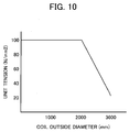
- a reversible cold rolling method for solving the above-mentioned first to third problems is a reversible cold rolling method including: a coil building-up step of sequentially unwinding strips from a plurality of coils to be subjected to a rolling step and joining the strips together by welding to build up a coil; a reversible rolling step of subjecting a strip unwound from the buildup coil to reversible rolling a predetermined number of times by a rolling mill; and a cutting step of cutting the coil in a final pass of the reversible rolling step to desired strip lengths to form a plurality of coils, the steps being performed on a rolling pass line, characterized in that the buildup coil has a coil outside diameter of not more than ⁇ 3000, and a rolling speed at the rolling mill in the cutting step is more than 0 mpm and not more than 50 mpm.
- the reversible cold rolling method according to a second invention for solving the above-mentioned second problem is the reversible cold rolling method according to the first invention, characterized in that a tension on a strip when the outside diameter of the buildup coil is larger is set to be gradually decreased as compared with a tension on the strip when the outside diameter is smaller.
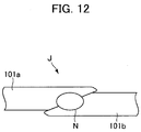
- the reversible cold rolling method according to a third invention for solving the above-mentioned first problem is the reversible cold rolling method according to any one of the first and second inventions, characterized in that a bent portion at a tail end of the strip unwound from the buildup coil is cut upon finish of a first pass of the reversible rolling step.
- the strip thickness meter used for the strip thickness control is disposed at a distance from the work rolls of the rolling mill; when the rolling speed is lowered, therefore, a feedback control of strip thickness by use of measured values obtained by the strip thickness meter leads to a time lag, whereby strip thickness control accuracy is lowered.
- the reversible cold rolling method according to a fourth invention for solving the above-mentioned newly generated problem is the reversible cold rolling method according to the first to third invention, characterized in that in the cutting step, entry-side rolling speed and entry-side strip thickness and delivery-side rolling speed at the rolling mill are measured, the strip thickness beneath work rolls of the rolling mill is computed based on the measured values, and a strip thickness control such as to obtain a desired strip thickness is performed by a hydraulic rolling reduction device possessed by the rolling mill.
- a problem that shape control accuracy is lowered is newly generated.
- a shape detector for measuring the shape of a strip is also disposed at a distance from the work rolls of the rolling mill, like the strip thickness meter; when the rolling speed is lowered, therefore, a time is taken from the shape recognition by the shape detector until shape correction by an actuator, so that shape control accuracy is lowered.
- a lowering in rolling speed leads to a rise in the coefficient of friction between the work roll and the strip, resulting in that the rolling load is raised and the strip shape is disturbed.
- the reversible cold rolling method according to a fifth invention for solving the above-mentioned newly generated problem is the reversible cold rolling method according to any one of the first to fourth inventions, characterized in that in the cutting step, strip shape is controlled by a roll bender control or a coolant control or a combination of both controls on the basis of the computation result of roll deflection due to fluctuations in rolling load at the rolling mill.
- the strip thickness control by the related art may be insufficient in accuracy.
- the reversible rolling method according to a sixth invention for solving the above-mentioned newly generated problem is the reversible cold rolling method according to any one of the first to fifth inventions, characterized in that a strip thickness meter is provided on a downstream side of the joining device for joining by welding in the coil building-up step; the strip thickness meter measures the strip thickness after joining, in the coil building-up step; and a feedforward strip thickness control is performed in a first pass of the reversible rolling step.
- the reversible cold rolling method according to a seventh invention for solving the above-mentioned fourth problem is the reversible cold rolling method according to any one of the first to sixth inventions, characterized in that a coil-building-up winding/unwinding device is operative to winding and unwinding the buildup coil and has a coil centering mechanism; the coil-building-up winding/unwinding device operates the coil centering mechanism at the time of winding the buildup coil, in the coil building-up step; and the coil-building-up winding/unwinding device operates the coil centering mechanism at the time of unwinding the buildup coil, in a first pass of the reversible rolling step.
- the reversible cold rolling method according to an eighth invention for solving the above-mentioned fifth problem is the reversible cold rolling method according to any one of the first to seventh inventions, characterized in that the order of feeding-in of coils is preliminarily controlled prior to the coil building-up step so that the absolute value of a strip thickness difference between a preceding coil and a succeeding coil will be not more than 1 mm.
- the reversible cold rolling method according to a ninth invention for solving the above-mentioned first to fifth problems is the reversible cold rolling method according to any one of the first to eighth inventions, characterized in that the joining in the coil building-up step is by a mash seam welding system.
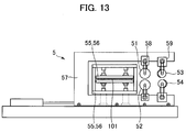
- a mash seam welding machine adopts a system in which materials to be joined together are lapped on each other and clamped between electrode wheels, and an electric current is passed through the lapped materials to cause contact resistance and internal resistance heating of the materials, whereby the materials are joined together.
- the joint portion upon completion of the joining shows an increased strip thickness of about 1.2 to 1.5 times the original thickness.
- the increase in thickness causes the joint portion to constitute a step, so that an excessive force is exerted on the rolls when the step passes the rolling mill.
- the step may be transferred to the work rolls as marks.
- the reversible cold rolling method according to a tenth invention for solving the above-mentioned newly generated problem similar to the fifth problem is the reversible cold rolling method according to any one of the first to ninth inventions, characterized in that a cross swaging treatment is performed immediately after the joining by the mash seam welding system.
- the reversible cold rolling method according to an eleventh invention is the reversible cold rolling method according to any one of the first to tenth inventions, characterized in that a cutting device is operative to cut a coil in the cutting step; and a part at which the coil is cut in the cutting step is set at a part immediately posterior to the passage of a joint portion through the cutting device.
- the reversible cold rolling method according to a twelfth invention is the reversible cold rolling method according to the eleventh invention, characterized in that a part at which the coil is cut in the cutting step is set at a part immediately anterior to the passage of the joint portion through the cutting device and at a part immediately posterior to the passage of the joint portion through the cutting device.
- the reversible cold rolling method according to a thirteenth invention is the reversible cold rolling method according to any one of the first to twelfth inventions, characterized in that the joining device is operative to join strips together by welding and has a strip heater; and the strip heater heats the strips to a temperature of not less than 100°C to not more than 400°C in the coil building-up step.
- the reversible cold rolling method according to a fourteenth invention is the reversible cold rolling method according to any one of the first to thirteenth inventions, characterized in that the rolling mill is of a two-stand type.
- the reversible cold rolling method according to a fifteenth invention is the reversible cold rolling method according to any one of the first to fourteenth inventions, characterized in that prior to start of a final pass of the reversible rolling step, work rolls are replaced by dulled work rolls in a condition where a strip is threaded the rolling mill, and then rolling in the final pass is performed.
- Reversible cold rolling equipment for solving the above-mentioned first to third problems is reversible cold rolling equipment for performing a plurality of passes of cold rolling while changing a rolling direction, by use of a unwinding device for sequentially unwinding strips from a plurality of input coils, a coil-building-up winding/unwinding device for joining the strips together by welding to form a buildup coil and winding and unwinding a strip of the buildup coil, a joining device disposed between the unwinding device and the coil-building-up winding/unwinding device, at least one reversible rolling mill, first and second winding/unwinding devices disposed respectively on an entry side and an delivery side of a first pass of the rolling mill, a cutting device for cutting the strip of the buildup coil, and a controller by which the unwinding device, the coil-building-up winding/unwinding device, the joining device, the cold rolling mill, the first and second winding/unwinding devices and the cutting device are
- the reversible cold rolling equipment according to a seventeenth invention for solving the above-mentioned first to third problems is the reversible cold rolling equipment according to the sixteenth invention, characterized in that the cutting device has an swing mechanism which swings in a rolling direction.
- the reversible cold rolling equipment according to an eighteenth invention for solving the above-mentioned second problem is the reversible cold rolling equipment according to any one of the sixteenth and seventeenth inventions, characterized in that the controller has a tension controlling function by which, during coil building-up and during reversible rolling, a tension on a strip when the coil outside diameter is larger is compared with, and is set to be lower than, a tension on the strip when the coil outside diameter is smaller.
- the reversible cold rolling equipment according to a nineteenth invention for solving the above-mentioned problem newly generated attendantly on the first and third problems is the reversible cold rolling equipment according to any one of the sixteenth to eighteenth inventions, characterized in that the controller has a strip thickness controlling function by which, during coil cutting by the cutting device, entry-side rolling speed and entry-side strip thickness and delivery-side rolling speed at the rolling mill are measured, a strip thickness beneath work rolls of the rolling mill is computed based on the measured values, and a strip thickness control such as to obtain a desired strip thickness is performed by a hydraulic rolling reduction device possessed by the rolling mill.
- the reversible cold rolling equipment according to a twentieth invention for solving the above-mentioned problem newly generated attendantly on the first and third problems is the reversible cold rolling equipment according to any one of the sixteenth to nineteenth inventions, characterized in that the controller has a shape controlling function by which, during cutting by the cutting device, a strip shape is controlled by a roll bender control or a coolant control or a combination of both controls on the basis of a computation result of roll deflection due to fluctuations in rolling load at the cold rolling mill.
- the reversible cold rolling equipment according to a twenty-first invention for solving the above-mentioned fourth problem is the reversible cold rolling equipment according to any one of the sixteenth to twentieth inventions, characterized in that the coil-building-up winding/unwinding device has a coil centering mechanism; and the controller has a coil centering function of controlling the coil-building-up winding/unwinding device so as to operate the coil centering mechanism at the time of winding the buildup coil, and to operate the coil centering mechanism at the time of unwinding the buildup coil.
- the reversible cold rolling equipment according to a twenty-second invention for solving the above-mentioned first and fifth problems is the reversible cold rolling equipment according to any one of the sixteenth to twenty-first inventions, characterized in that the joining device is a mash seam welding machine.
- the reversible cold rolling equipment according to a twenty-third invention for solving the above-mentioned fifth problem is the reversible cold rolling equipment according to the twenty-second invention, characterized in that the mash seam welding machine as the joining device has a swaging roller having a mechanism for inclining an axis of the swaging roller relative to a horizontal plane perpendicular to a weld line.
- the reversible cold rolling equipment according to a twenty-fourth invention is the reversible cold rolling equipment according to any one of the sixteenth to twenty-third inventions, characterized in that the cold rolling mill is of a two-stand type.
- the buildup coil is formed in the coil building-up step, and the buildup coil is subjected to reversible rolling a predetermined number of times in the reversible rolling step.
- an unrolled portion is generated only at an innermost circumferential portion and an outermost circumferential portion of the buildup coil, so that off-gage rate can be remarkably lowered. Further, there is little portion that is rolled at a non-steady rolling speed, so that strip thickness accuracy is enhanced. In other words, a high efficiency and a high yield comparable to those according to the related art described in Patent Document 2 can be maintained.
- the winding/unwinding device to which the collapsible type reel is applied is capable of performing both a winding and unwinding operation and a carrying-out operation.
- the rolling speed of the rolling mill is set to be more than 0 mpm and not more than 50 mpm. This ensures that after coil cutting, a series of operations of extracting a coil, carrying out the coil and then continuously winding the next coil can be performed using a single winding/unwinding device.
- the rolling speed of the rolling mill during the cutting step is more than 0 mpm and not more than 20 mpm, more preferably more than 0 mpm and not more than 10 mpm, still more preferably more than 0 mpm and not more than 5 mpm, and further preferably more than 0 mpm and not more than 2 mpm.
- This ensures that the distance between the cutting device and the winding/unwinding device can be shortened, and equipment length can be thereby shortened. As a result, initial investment expenditure can be cut down.
- stop marks of the work rolls can be prevented from being formed on the strip.
- the cutting device has an swing mechanism which oscillates in the rolling direction.
- the rolling speed of the rolling mill during the cutting step set to be more than 0 mpm and not more than 50 mpm, it is possible to apply a cutting device having an swing mechanism that is comparatively inexpensive and, hence, to curtail the initial cost.
- tension control is conducted, whereby it is possible to restrict a coil tightening force exerted on the coil and to prevent the winding/unwinding device from being enlarged due to an enlargement of coil outside diameter.
- a bent portion at the tail end of the strip unwound from the buildup coil is cut, upon completion of the first pass of the reversible rolling step, whereby the reversible rolling line of an existing equipment (the related art described in Patent Document 1) can be improved in an inexpensive manner.
- a strip thickness meter used for strip thickness control is disposed at a distance from the work rolls of the rolling mill.
- a feedback control of strip thickness by use of measured values obtained from the strip thickness meter leads to a lowering in strip thickness control accuracy due to a time lag.
- the entry-side rolling speed and the entry-side strip thickness and the delivery-side rolling speed of the cold rolling mill are measured, the strip thickness beneath the work roll of the cold rolling mill is computed based on the measured values, and a strip thickness control is conducted by a hydraulic rolling reduction device possessed by the cold rolling mill so that a desired strip thickness will be obtained. Therefore, the accuracy of strip thickness can be maintained.
- a problem of lowering in shape control accuracy is newly generated.
- a shape detector for measuring the shape of the strip is also disposed at a distance from the work rolls of the rolling mill.
- time is taken after the recognition of strip shape by the shape detector until the correction of strip shape by an actuator, whereby shape control accuracy is lowered.
- a lowering in rolling speed generally raises the coefficient of friction between the work roll and the strip, resulting in a rise in rolling load, changing the roll deflection, whereby the strip shape is disturbed.
- strip shape is controlled by a roll bender control or a coolant control or a combination of both controls on the basis of the computation result of roll warpage due to fluctuations in the rolling load at the rolling mill. This makes it possible to compensate for the detection lag and to maintain the shape of the strip.
- the strip thickness control according to the related art may result in an insufficient accuracy.
- a feedforward strip thickness control is conducted; specifically, prior to the reversible rolling step, a rolling reduction control quantity is predicted and controlled, whereby a strip thickness control accuracy can be maintained.
- the coil centering mechanism is operated when the buildup coil is wound by the coil-building-up winding/unwinding device in the coil building-up step, whereby the buildup coil can be prevented from being formed in a telescopic state.
- the coil-building-up winding/unwinding device operates the coil centering mechanism at the time of unwinding the buildup coil. This ensures that even if the buildup coil is formed in a telescopic state, a control can be performed so that the cold rolling mill and the center of the strip are made to conform to each other and rolling is maintained.
- the coil end faces can be prevented from getting out of alignment, and the problem relating to the telescopic state of the buildup coil can be solved.
- the order of feeding-in of coils into the unwinding device is preliminarily controlled so that the absolute value of a strip thickness difference between a preceding coil and a succeeding coil will be not more than 1 mm, preferably not more than 0.5 mm. This makes it possible to reduce the possibility that, due to a step at the joint portion located in an inner layer portion of the built-up coil, a crack might be transferred to the adjacent coil layers.
- joining is conducted by use of a joining device of a mash seam welding system which is inexpensive. This makes it possible to solve the problem relating to cost-effectiveness, in a small- to medium-scale production facility with an annual output of about 300,000 to 600,000 tons.
- a mash seam welding machine adopts a system wherein the materials to be joined are lapped on each other and clamped between electrode wheels, and an electric current is passed through the materials to cause contact resistance and internal resistance heating of the materials, whereby the materials are joined together.
- the joint portion upon completion of the joining shows an increased strip thickness of about 1.2 to 1.5 times the original thickness.
- the increase in thickness causes the joint portion to constitute a step, so that an excessive force is exerted on the rolls when the step passes the rolling mill.
- the step may be transferred to the work rolls as marks.
- a cross swaging treatment for rolling the joint portion showing an increased strip thickness is conducted by inclining swaging rollers after the mash seam welding, whereby the step can be smoothened.
- the product coils may be required to have a further accuracy.
- coil cutting in the final pass is performed immediately posterior to the passage of the joint portion through the cutting device.
- the joint portion can be disposed at the outer surface of the cut coil, and a treatment of the joint portion after coil extraction can be easily carried out.
- the coil cutting in the final pass is conducted immediately anterior to the passage of the joint portion through the cutting device and immediately posterior to the passage of the joint portion through the cutting device. This ensures that the joint portion is not wound around the product coil, so that the need for an after-treatment of the joint portion can be eliminated.
- the strip heater heats the strip to a temperature of not less than 100°C to not more than 400°C, whereby a magnetic steel sheet or strip or a magnesium sheet with high quality can be stably rolled.
- rolling is conducted using a two-stand type cold rolling mill. This makes it possible to reduce the number of rolling passes to be conducted until a desired strip thickness is obtained and, thereby, to shorten the time necessary for the reversible rolling step. As a result, it is possible to improve the tact balance between the coil building-up step and the reversible rolling step, and to enhance production efficiency.
- the work rolls are replaced by dulled work rolls in a condition where a strip is threaded the cold rolling mill, before the start of the final-pass rolling, and then the final-pass rolling is conducted.
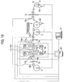
- Fig. 1 is a schematic view of cold-rolled material equipment according to the first embodiment of the present invention.
- the cold-rolled material equipment includes, as main components: a reversible cold rolling mill 1; a unwinding device 2 for unwinding a strip of an input coil 101; a winding/unwinding device 3 (first winding/unwinding device) disposed on the entry side of a first pass of the cold rolling mill 1; a winding/unwinding device 4 (second winding/unwinding device) disposed on the delivery side of the first pass of the cold rolling mill 1; a joining device 5 disposed downstream of the unwinding device 2 for forming a buildup coil 102 from a plurality of input coils 101; a winding/unwinding device 6 for coil building-up for winding and unwinding the strip of the buildup coil 102; a cutting devices 7 for cutting up the strip of the buildup coil 102 in a final pass to form output coils 103; and a controller 20 for controlling the cold rolling mill 1, the unwinding device 2, the winding/unwinding devices 3,
- the reversible cold rolling mill 1 is, for example, a six-high UC mill which includes top and bottom work rolls 11, 11 which make direct contact with a work (material to be rolled) and roll the work, top and bottom intermediate rolls 12, 12 which support the work rolls in the vertical direction, and top and bottom back-up rolls 13, 13 which support the intermediate rolls 12, 12 in the vertical direction.
- a hydraulic rolling reduction device 14 is provided beneath the bottom back-up roll 13. Based on a command, the hydraulic rolling reduction device 14 moves vertically a bearing for the bottom back-up roll 13, whereby a strip is reduced to obtain a predetermined rolling reduction.
- a load meter 15 is provided on the upper side of the top back-up roll 13, and the rolling reduction of the rolls is controlled correspondingly to a variation in load that is detected by the load meter 15. This series of operations is referred to as reduction control.
- a strip thickness meter 16a, a plate velocity meter 17a and a shape meter 18a are provided on the entry side of the first pass of the cold rolling mill 1
- a strip thickness meter 16b, a plate velocity meter 17b and a shape meter 18b are provided on the delivery side of the first pass of the cold rolling mill 1.
- the unwinding device 2 includes a collapsible type reel having an expansion/collapse, sets the input coil 101, and unwinds a strip of the input coil 101.
- the unwinding device 2 includes a coil centering mechanism 22 (described later).
- the winding/unwinding device 3 and the winding/unwinding device 4 each repeats winding and unwinding a work between the winding/unwinding device 3 and the winding/unwinding device 4, whereby a plurality of passes of cold rolling are carried out while changing the rolling direction.
- the winding/unwinding device 3 and the winding/unwinding device 4 include a collapsible type reel having an expansion/collapse and carry out the output coil 103 which is formed by cutting.
- the joining device 5 joins the tail end of the strip of a first input coil 101a already unwound with the leading end of the strip of a second input coil 101b subsequently unwound, and subsequently and similarly joins the tail end of the strip of the second input coil 101b with the leading end of the strip of a third input coil 101c, to form a buildup coil 102.
- the winding/unwinding device 6 (for coil building-up) sequentially winds the strips of the buildup coil 102 joined by the joining device 5, and unwinds the strip of the buildup coil 102 in the first pass.
- the winding/unwinding device 6 has a solid type reel which does not have an expansion/collapse.
- the winding/unwinding device 6 may not necessarily have the solid type reel, but may have a collapsible type reel.
- the winding/unwinding device 6 has a coil centering mechanism 23 (described later).
- the cutting device 7 includes a cutting device 7a and a cutting device 7b.
- the cutting device 7a is disposed between the cold rolling mill 1 and the winding/unwinding device 3, and cuts up the strip of the buildup coil 102 in a pass in which the winding in a final pass is completed at the winding/unwinding device 3.
- the cutting device 7b is disposed between the cold rolling mill 1 and the winding/unwinding device 4, and cuts up the strip of the buildup coil 102 in a pass in which the winding in the final pass is completed at the winding/unwinding device 4.
- the cutting devices 7a and 7b each have an swing mechanism (not shown).
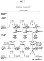
- Figs. 2 to 4 are control flows showing the procedures executed by the controller 20. Dotted lines indicate relationships among the devices 1 to 7. Description will be made of a control in the case where a buildup coil 102 is formed from three input coils 101, four passes of rolling are conducted, and thereafter three output coils 103 are formed.
- Figs. 5 to 7 are timetables for each of the devices 1 to 7 corresponding to the control flows, and the same step numbers as in Figs. 2 to 4 are given to those parts of the timetables which correspond to the procedure steps in the control flows.
- the controller 20 controls the unwinding device 2 in the following manner.
- a first input coil 101a is fed into and mounted onto the unwinding device 2
- the unwinding device 2 unwinds a strip of the first input coil 101a at a speed (hereafter referred to as passing speed, for convenience) comparable to the speed at which the strip is threaded the rolling mill (S0201).
- passing speed a speed comparable to the speed at which the strip is threaded the rolling mill
- S0202 steady speed
- the steady speed means a maximum speed at which the capability of the cold rolling mill can be exhibited to the utmost (hereafter the same applies also to the steady speeds at the winding/unwinding devices 3 and 4).
- the unwinding device 2 Upon unwinding the strip tail end of the first input coil 101a, the unwinding device 2 is stopped (S0203).
- the unwinding device 2 When a second input coil 101b is fed into and mounted onto the unwinding device 2, the unwinding device 2 unwinds a strip of the second input coil 101b to the joining device 5 at the passing speed, and, when the strip leading end of the second input coil 101b is fed out to a joining position of the joining device 5, the unwinding device 2 stops unwinding (S0204).
- the unwinding device 2 Upon joining between the first input coil 101a and the second input coil 101b, the unwinding device 2 unwinds the remaining strip of the second input coil 101b at the steady speed (S0205). The unwinding device 2 is stopped upon unwinding the strip tail end of the second input coil 101b (S0206).
- S0207 When a third input coil 101c is fed into and mounted onto the unwinding device 2, the unwinding device 2 unwinds a strip of the third input coil 101c to the joining device 5 at the threading speed, and, when the strip leading end of the third input coil 101c is fed out to the joining position of the joining device 5, the unwinding device 2 stops unwinding (S0207).
- the unwinding device 2 unwinds the remaining strip of the third input coil 101c at the steady speed (S0208).
- the unwinding device 2 is stopped (S0209).
- the controller 20 controls the joining device 5 as follows.
- the joining device 5 joins the first input coil 101a and the second input coil 101b (S0501).
- the strip tail end of the second input coil 101b reaches and is stopped at the joining position and the strip leading end of the third input coil 101c is fed out to the joining position of the joining device 5
- the joining device 5 joins the second input coil 101b and the third input coil 101c (S0502).
- the controller 20 controls the winding/unwinding device 6 (for coil building-up) in the following manner.
- the winding/unwinding device 6 grips the strip leading end of the first input coil 101a (S0601).
- the winding/unwinding device 6 winds the strip of the first input coil 101a at the steady speed (S0602), and, when the strip tail end of the first input coil 101a reaches the joining device 5, the winding/unwinding device 6 is decelerated and stops winding (S0603).
- the winding/unwinding device 6 Upon joining between the first input coil 101a and the second input coil 101b, the winding/unwinding device 6 winds the remaining strip of the first input coil 101a at the steady speed, and, subsequently, winds the strip of the second input coil 101b joined (S0604). Upon arrival of the strip tail end of the second input coil 101b at the joining device 5, the winding/unwinding device 6 is decelerated and stops winding (S0605). Upon joining between the second input coil 101b and the third input coil 101c, the winding/unwinding device 6 winds the remaining strip of the second input coil 101b at the steady speed, and, subsequently, winds the strip of the third input coil joined (S0606).
- the winding/unwinding device 6 is stopped (S0607).
- the buildup coil 102 is formed from the three coils 101a, 101b and 101c (S0608).
- the outside diameter of the buildup coil 102 is not more than ⁇ 3000.
- the controller 20 controls the cold rolling mill 1 as follows. Prior to the start of first-pass rolling, the strip leading end of the buildup coil 102 is unwound from the winding/unwinding device 6 to the winding/unwinding device 4 and is gripped by the winding/unwinding device 4, whereon the cold rolling mill 1 is subjected to a rolling reduction control (S1101). When the preparation for rolling is completed, the cold rolling mill 1 is accelerated to the steady rolling speed, and performs the first-pass rolling at the steady rolling speed (S1102). When the strip tail end of the buildup coil 102 is unwound and fed out from the winding/unwinding device 6, the cold rolling mill 1 is decelerated. When the strip tail end of the buildup coil 102 arrives at a position immediately anterior to the cold rolling mill 1, the cold rolling mill 1 stops rolling (S1103), and the first-pass rolling is finished (S1111).
- the cold rolling mill 1 is subjected to a rolling reduction control (S2101).
- the cold rolling mill 1 is accelerated to the steady rolling step in the reverse direction to that in the first pass, and second-pass rolling is performed at the steady rolling speed (S2102).
- the cold rolling mill 1 is subjected to a rolling reduction control such as to obtain a desired strip thickness (S3101).
- a rolling reduction control such as to obtain a desired strip thickness
- the cold rolling mill 1 is accelerated to the steady rolling speed, and performs the third-pass rolling at the steady rolling speed (S3102).
- the steady rolling speed means a maximum speed at which the capability of the cold rolling mill can be exhibited to the utmost, in obtaining a desired strip thickness.
- the steady rolling speed in reversible cold rolling equipment is generally in the range of 400 to 1400 mpm.
- the controller 20 controls the winding/unwinding device 6 (for coil building-up) in the following manner.
- the winding/unwinding device 6 unwinds the strip of the buildup coil 102, which has been formed in the coil building-up step, to the winding/unwinding device 4 at the threading speed (S1601).
- the winding/unwinding device 6 Upon completion of the preparation for the first-pass rolling, the winding/unwinding device 6 unwinds the strip of the buildup coil 102 according to the rolling speed of the cold rolling mill 1 which is rolling at the steady rolling speed (S1602), and, when the strip is unwound completely, the winding/unwinding device 6 is stopped (S1603).
- the controller 20 controls the winding/unwinding device 3 (first winding/unwinding device) as follows.
- the winding/unwinding device 3 grips the strip end (S2301).
- the winding/unwinding device 3 winds the strip of the buildup coil 102 (S2302), and is decelerated and stopped in conformity with the finishing of the second-pass rolling (S2303).
- the winding/unwinding device 3 unwinds the strip of the buildup coil 102 (S3301), and it is decelerated and stopped in conformity with the finishing of the third pass (S3302).
- the controller 20 controls the winding/unwinding device 4 (second winding/unwinding device) in the following manner.
- the winding/unwinding device 4 grips the strip end (S1401).
- the winding/unwinding device 4 winds the strip of the buildup coil 102 (S1402), and it is decelerated and stopped in conformity with the finishing of the first-pass rolling (S1403).
- the winding/unwinding device 4 unwinds the strip of the buildup coil 102 at the threading speed in the reverse direction to that in the first pass to the winding/unwinding device 3 (S2401).
- the winding/unwinding device 4 unwinds the strip of the buildup coil 102 according to the rolling speed of the cold rolling mill 1 which is rolling at the steady rolling speed (S2402).
- the winding/unwinding device 4 is decelerated and stopped in conformity with the finishing of the second-pass rolling (S2403).
- the winding/unwinding device 4 winds the strip of the buildup coil 102 (S3401), and it is decelerated and stopped in conformity with the finishing of the third-pass rolling (S3402).
- the buildup coil is divided (cut up) into three output coils 103a to 103c.
- the coil building-up step and the first to third passes of the reversible rolling step are steps which are substantially common to the present embodiment and a second related art (described later).
- the fourth pass (final pass) in the reversible rolling step and the cutting step are characteristic of the present embodiment.
- the controller 20 controls the cold rolling mill 1 in the following manner. After the finish of the third-pass rolling and before the start of a fourth-pass rolling, the cold rolling mill 1 is subjected to a rolling reduction control so that a desired strip thickness will be obtained (S4101). When the preparation for rolling is completed, the cold rolling mill 1 is accelerated in the reverse direction to that in the third pass to a steady rolling speed, and the fourth-pass (final-pass) rolling is conducted at the steady rolling speed (S4102).
- the cold rolling mill 1 is decelerated and conducts rolling at a low speed (for example, 2 mpm) (S4103).
- a low speed for example, 2 mpm
- the cold rolling mill 1 is accelerated again to a steady rolling speed, and rolls the remaining strip in the final pass of the buildup coil 102 (S4104).
- the cold rolling mill 1 is decelerated and performs rolling at a low speed (for example, 2 mpm) (S4105).
- a low speed for example, 2 mpm
- the cold rolling mill 1 is accelerated again to a steady rolling speed, and rolls the remaining strip in the final pass of the buildup coil 102 at the steady rolling speed (S4106).
- the cold rolling mill 1 is decelerated and conducts rolling at a low speed (for example, 2 mpm) (S4107).
- a low speed for example, 2 mpm
- the cold rolling mill 1 stops rolling (S4108), and the fourth-pass (final-pass) rolling is finished (S4109).
- the controller 20 controls the winding/unwinding device 3 (first winding/unwinding device) as follows.
- the winding/unwinding device 3 winds the strip of the buildup coil 102 (S4301).
- the winding/unwinding device 3 winds the strip of the buildup coil 102 (S4302).
- the winding/unwinding device 3 winds the remaining strip at a high speed (S4303).
- the winding/unwinding device 3 After completion of the winding, the winding/unwinding device 3 permits the first output coil 103a to be extracted therefrom and carried out (S4304). The leading end of the strip unwound subsequently (the leading end of the second input coil 103b) is wound by a belt wrapper (S4305). Upon completion of the preparation for winding, according to the rolling speed in the fourth pass (final pass) of the cold rolling mill 1 which is rolling at a steady rolling speed, the winding/unwinding device 3 winds the strip of the buildup coil 102 (S4306).
- the winding/unwinding device 3 Upon winding of a predetermined length of the strip, according to the rolling speed of the cold rolling mill 1 which is rolling at a low speed (for example, 2 mpm) in conformity with the procedure of cutting, the winding/unwinding device 3 winds the strip of the buildup coil 102 (S4307). After cutting of the second output coil 103b, the winding/unwinding device 3 winds the remaining strip at a high speed (S4308), and, after completion of the winding, the winding/unwinding device 3 permits the second output coil 103b to be extracted therefrom and carried out (S4309). The leading end of the strip unwound subsequently (the leading end of the third input coil 103c) is wound by the belt wrapper (S4310).
- the winding/unwinding device 3 Upon completion of the preparation for winding, according to the rolling speed in the fourth pass (final pass) of the cold rolling mill 1 which is rolling at a steady rolling speed, the winding/unwinding device 3 winds the strip of the buildup coil 102 (S4311). Upon winding of a predetermined length of the strip, according to the rolling speed of the cold rolling mill 1 which is rolling at a low speed (for example, 2 mpm) in conformity with the procedure of cutting, the strip of the buildup coil 102 is wound (S4312). After cutting of the third output coil 103b, the winding/unwinding device 3 winds the remaining strip at a high speed (S4313). After completion of the winding, the winding/unwinding device 3 permits the third output coil 103c to be extracted therefrom and carried out (S4314).
- the controller 20 controls the winding/unwinding device 4 (second winding/unwinding device) as follows. According to the rolling speed in the fourth pass (final pass) of the cold rolling mill 1 which is rolling at a steady rolling speed, the winding/unwinding device 4 unwinds the strip of the buildup coil 102 (S4401). Upon unwinding of a predetermined length of the strip, according to the rolling speed of the cold rolling mill 1 which is rolling at a low speed (for example, 2 mpm) in conformity with the procedure of cutting, the winding/unwinding device 4 unwinds the strip of the buildup coil 102 (S4402).
- a low speed for example, 2 mpm
- the winding/unwinding device 4 unwinds the strip of the buildup coil 102 (S4403).
- the winding/unwinding device 4 Upon unwinding of a predetermined length of the strip, according to the rolling speed of the cold rolling mill 1 which is rolling at a low speed (for example, 2 mpm) in conformity with the procedure of cutting, the winding/unwinding device 4 unwinds the strip of the buildup coil 102 (S4404).
- the winding/unwinding device 4 unwinds the strip of the buildup coil 102 (S4405).
- the winding/unwinding device 4 Upon unwinding of a predetermined length of the strip, according to the rolling speed of the cold rolling mill 1 which is rolling at a low speed (for example, 2 mpm) in conformity with the procedure of cutting, the winding/unwinding device 4 unwinds the strip of the buildup coil 102 (S4406). After cutting of the third output coil 103b, the winding/unwinding device 4 winds the remaining strip, and permits an off-gage coil 103d to be extracted therefrom and carried out (S4407).
- the controller 20 controls the cutting device 7a in the following manner.
- the controller 20 computes each of cutting positions from respective coil outside diameters and reel rotational speeds at the winding/unwinding devices 3 and 4.
- the cutting device 7a cuts the first output coil 103a off the strip of the buildup coil 102 at the cutting position (S4701), cuts the second output coil 103b off the remaining strip at the next cutting position (S4702), and cuts the third output coil 103c off the remaining strip at a further cutting position (S4703).
- controller 20 computes the cutting positions on the basis of the coil outside diameters and reel rotational speeds in the present embodiment
- a method may be adopted in which boring of holes in the cutting positions or the like is applied and the cutting positions are detected by a cutting position detector (not shown) or the like.
- a method may also be adopted in which the cutting positions are grasped through computation of distances by use of a distance measuring function of the strip velocity meter.
- the strip of the first input coil 101a is unwound at a speed (hereinafter, referred to as passing speed, for convenience) that is approximate to a threading speed, and the strip is gripped by a winding/unwinding device 6 and is wound further by a several-turn amount.
- passing speed a speed that is approximate to a threading speed
- the strip is gripped by a winding/unwinding device 6 and is wound further by a several-turn amount.
- the strip of the first input coil 101a is unwound from the unwinding device 2 at a steady speed, to be wound onto the winding/unwinding device 6 (S0201 ⁇ S0601 ⁇ S0202 ⁇ S0602).
- the steady speed means a maximum speed at which the capabilities of the unwinding device 2 and the winding/unwinding device 6 can be exhibited to the utmost (hereinafter, the same applies also to the steady speeds at the winding/unwinding devices 3 and 4).
- the strip tail end of the first input coil 101a and the strip leading end of the second input coil 101b are joined together by the joining device 5 (S0501).
- the remaining strip of the first input coil 101a is wound onto the winding/unwinding device 6; subsequently, the strip of the second input coil 101b joined is unwound from the unwinding device 2 at the steady speed, and is wound onto the winding/unwinding device 6 (S0205 ⁇ S0604).
- the strip tail end of the second input coil 101b and the strip leading end of the third input coil 101c are joined together by the joining device 5 (S0502).
- the remaining strip of the second input coil 101b is wound onto the winding/unwinding device 6; subsequently, the strip of the third input coil 101b joined is unwound from the unwinding device 2 and wound onto the winding/unwinding device 4 (S0208 ⁇ S0606).
- the buildup coil 102 is formed at the winding/unwinding device 6 (S0608).
- the outside diameter of the buildup coil 102 is not more than ⁇ 3000.
- the strip of the buildup coil 102 is unwound from the winding/unwinding device 6 at a threading speed, the strip leading end is gripped by the winding/unwinding device 4, and the strip is wound further by a several-turn amount. Thereafter, the cold rolling mill 1 is subjected to a rolling reduction control (S1601 ⁇ S1401 ⁇ S1101).
- the cold rolling mill 1 is subjected to a feedback control such as to obtain a command rolling speed.
- the winding/unwinding device 6 is subjected to a tension feedback control such that the tension on the strip between the winding/unwinding device 6 and the cold rolling mill 1 will be a predetermined value.
- the winding/unwinding device 4 is also subjected to a tension feedback control such that the tension on the strip between the winding/unwinding device 4 and the cold rolling mill 1 will be a predetermined value.
- the strip of the buildup coil 102 is rolled at a steady rolling speed by the cold rolling mill 1, and, according to the rolling speed at the cold rolling mill 1, the strip is unwound from the winding/unwinding device 6 and is wound onto the winding/unwinding device 4 (S1602 ⁇ S1102 ⁇ S1402).
- the cold rolling mill 1 is stopped to finish the first pass, and the winding/unwinding device 4 and the winding/unwinding device 6 are stopped according to the stopping of the cold rolling mill 1 (S1103 ⁇ S1603 ⁇ S1403 ⁇ S1104).
- the rolling direction is changed to the reverse direction, and the second pass is started.
- the strip of the buildup coil 102 is unwound from the winding/unwinding device 4 at a threading speed, the strip tail end (the strip leading end in the second-pass direction) is gripped by the winding/unwinding device 3, and the strip is wound further by a several-turn amount. Thereafter, the cold rolling mill 1 is subjected to a rolling reduction control (S2401 ⁇ S2301 ⁇ S2101).
- the strip of the buildup coil 102 is rolled at a steady rolling speed by the cold rolling mill 1, and, according to the rolling speed of the cold rolling mill 1, the strip is unwound from the winding/unwinding device 4 and wound onto the winding/unwinding device 3 (S2402 ⁇ S2102 ⁇ S2302).
- the cold rolling mill 1 is stopped to finish the second pass, and the winding/unwinding device 3 and the winding/unwinding device 4 are stopped according to the stopping of the cold rolling mill 1 (S2103 ⁇ S2403 ⁇ S2303 ⁇ S2104).
- the cold rolling mill 1 In the condition where the strip of the buildup coil 102 is gripped by the winding/unwinding device 4 and the winding/unwinding device 3, the cold rolling mill 1 is subjected to a rolling reduction control, the strip of the buildup coil 102 is rolled at a steady rolling speed by the cold rolling mill 1, and, according to the rolling speed of the cold rolling mill 1, the strip is unwound from the winding/unwinding device 3 and wound onto the winding/unwinding device 4 (S3101 ⁇ S3102 ⁇ S3301 ⁇ S3401).
- the cold rolling mill 1 is stopped to finish the third pass, and the winding/unwinding device 3 and the winding/unwinding device 4 are stopped according to the stopping of the cold rolling mill 1 (S3103 ⁇ S3302 ⁇ S3402 ⁇ S3104).
- the operations relating to the coil building-up step and the first to third passes of the reversible rolling step as above-mentioned are operations which are common to the present embodiment and the second related art (described later). Meanwhile, the operations relating to the fourth pass (final pass) of the reversible rolling step and the cutting step are operations which are characteristic of the present embodiment.
- the cold rolling mill 1 In the condition where the strip of the buildup coil 102 is gripped by the winding/unwinding device 4 and the winding/unwinding device 3, the cold rolling mill 1 is subjected to a rolling reduction control, the strip of the buildup coil 102 is rolled at a steady rolling speed by the cold rolling mill 1, and, according to the rolling speed of the cold rolling mill 1, the strip is unwound from the winding/unwinding device 4 and wound onto the winding/unwinding device 3 (S4101 ⁇ S4102 ⁇ S4301 ⁇ S4401).
- the cold rolling mill 1 Immediately before the strip corresponding to the first output coil 103a is wound onto the winding/unwinding device 3, the cold rolling mill 1 is decelerated to a predetermined low speed, the strip of the buildup coil 102 is rolled at the low speed (for example, 2 mpm) by the cold rolling mill 1, and, according to the rolling speed of the cold rolling mill 1, the strip is unwound from the winding/unwinding device 4 and wound onto the winding/unwinding device 3 (S4103 ⁇ S4302 ⁇ S4402).
- the strip of the buildup coil 102 is cut at a strip cutting position by the cutting device 7a, and the remaining strip of the first output coil 103a thus cut off is wound at a high speed onto the winding/unwinding device 3.
- the winding/unwinding device 3 is stopped, and the first output coil 103a is extracted from the winding/unwinding device 3 and carried out (S4701 ⁇ S4303 ⁇ S4304).
- a collapsible type reel is applied to the winding/unwinding device 3, as above-mentioned.
- the remaining strip of the buildup coil 102 having been cut is rolled at a low speed by the cold rolling mill 1, and is unwound from the winding/unwinding device 4 according to the rolling speed of the cold rolling mill 1.
- the leading end of the strip (corresponding to the second input coil 103b) fed out is wound by the belt wrapper of the winding/unwinding device 3 (S4305).
- the remaining strip of the buildup coil 102 is rolled at a steady rolling speed by the cold rolling mill 1, and, according to the rolling speed of the cold rolling mill 1, the strip is unwound from the winding/unwinding device 4 and wound onto the winding/unwinding device 3 (S4104 ⁇ S4403 ⁇ S4306).
- the cold rolling mill 1 Immediately before the strip corresponding to the second output coil 103b is wound onto the winding/unwinding device 3, the cold rolling mill 1 is decelerated to a predetermined low speed, the strip of the buildup coil 102 is rolled at the low speed by the cold rolling mill 1, and, according to the rolling speed of the cold rolling mill 1, the strip is unwound from the winding/unwinding device 4 and wound onto the winding/unwinding device 3 (S4105 ⁇ S4404 ⁇ S4307).
- the strip of the buildup coil 102 is cut at the strip cutting position by the cutting device 7a, and the remaining strip of the second output coil 103b thus cut off is wound at a high speed onto the winding/unwinding device 3.
- the winding/unwinding device 3 is stopped, and the second output coil 103b is extracted from the winding/unwinding device 3 and carried out (S4702 ⁇ S4308 ⁇ S4309).
- the remaining strip of the buildup coil 102 having been cut is rolled at a low speed by the cold rolling mill 1, and the strip is unwound from the winding/unwinding device 4 according to the rolling speed of the cold rolling mill 1.
- the leading end of the strip (corresponding to the third input coil 103c) thus fed out is wound by the belt wrapper of the winding/unwinding device 3 (S4310).
- the remaining strip of the buildup coil 102 is rolled at the steady rolling speed by the cold rolling mill 1, and, according to the rolling speed of the cold rolling mill 1, the strip is unwound from the winding/unwinding device 4 and wound onto the winding/unwinding device 3 (S4106 ⁇ S4405 ⁇ S4311).
- the cold rolling mill 1 Immediately before the strip corresponding to the third output coil 103c is wound onto the winding/unwinding device 3, the cold rolling mill 1 is decelerated to a predetermined low speed, the strip of the buildup coil 102 is rolled at the low speed by the cold rolling mill 1, and, according to the rolling speed of the cold rolling mill 1, the strip is unwound from the winding/unwinding device 4 and wound onto the winding/unwinding device 3 (S4107 ⁇ S4406 ⁇ S4312).
- the strip of the buildup coil 102 is cut at a strip cutting position by the cutting device 7a, and the remaining strip of the third output coil 103c thus cut off is wound at a high speed onto the winding/unwinding device 3.
- the winding/unwinding device 3 is stopped, and the third output coil 103c is extracted from the winding/unwinding device 3 and carried out (S4703 ⁇ S4313 ⁇ S4314).
- the cold rolling mill 1 stops rolling to finish the fourth pass, the remaining strip of the buildup coil 102 thus cut is wound onto the winding/unwinding device 4, and the off-gage coil 103d thus wound is extracted from the winding/unwinding device 4 and carried out (S4108 ⁇ S4109 ⁇ S4407).
- a collapsible type reel is applied to the winding/unwinding device 4, as above-mentioned.
- the output coils 103a to 103c are carried out from the winding/unwinding device 3, whereas the off-gage coil 103d is carried out from the winding/unwinding device 4.
- the strip of the buildup coil 102 is cut by the cutting device 7b, the output coils 103a to 103c are extracted from the winding/unwinding device 4 and carried out, whereas the off-gage coil 103d is carried out from the winding/unwinding device 3.
- Fig. 8 is a schematic illustration of cold-rolled material equipment according to the first related art.
- the same components as those in Fig. 1 are denoted by the same reference numerals as used in Fig. 1 .
- the cold-rolled material equipment (RCM equipment) includes, as main components: a reversible cold rolling mill 1; a unwinding device 2 which unwinds a strip to the cold rolling mill 1 in a first pass; a winding/unwinding device 3 disposed on the entry side of the first pass of the cold rolling mill 1; a winding/unwinding device 4 disposed on the delivery side of the first pass of the cold rolling mill 1; and a controller 20 by which the cold rolling mill 1, the unwinding device 2, and the winding/unwinding devices 3 and 4 are controlled.
- First-pass rolling is started by the cold rolling mill 1 after the input coil 101a is fed into the unwinding device 2, the strip leading end is threaded the cold rolling mill 1 and gripped by the winding/unwinding device 4, the strip is wound further by a several-turn amount, and the preparation for rolling such as tension application and rolling reduction setting is completed.
- the first-pass rolling is finished when the strip tail end comes to a position immediately anterior to the cold rolling mill 1.
- second-pass rolling is started by the cold rolling mill 1 after the strip leading end is threaded the cold rolling mill 1 in the reverse direction to that in the first pass, the strip leading end is gripped by the winding/unwinding device 3, the strip is wound further by a several-turn amount, and the preparation for rolling such as tension application and rolling reduction setting is completed.
- the second-pass rolling is finished in the condition where a strip end portion in a several-turn amount is gripped by the winding/unwinding device 4.
- the third-pass rolling is started by the cold rolling mill 1.
- the third-pass rolling is finished in the condition where a strip end portion in a several-turn amount is gripped by the winding/unwinding device 3.
- the fourth-pass rolling is started by the cold rolling mill 1.
- the output coil 103a after the fourth-pass rolling is wound onto the winding/unwinding device 3, is extracted therefrom, and is carried out.
- a collapsible type reel is applied to the winding/unwinding device 3, as above-mentioned.
- the input coil 101b is fed into the unwinding device 2
- the output coil 103b is carried out from the winding/unwinding device 3
- the input coil 101c is fed into the unwinding device 2
- the output coil 103c is carried out from the winding/unwinding device 3.
- the strip leading end and tail end portions of the output coils 103a to 103c are made to be unrolled portions; therefore, there has been the problem of a high off-gage rate of about 2.5%.
- the reversible rolling is conducted a total of 12 times to the three coils, there has been the problem that the actual rolling time in the operation time is short and production efficiency is poor.
- the second related art solves the problems involved in the first related art.
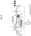
- Fig. 9 is a schematic view of cold-rolled material equipment according to the second related art.
- the same components as those in Fig. 1 are denoted by the same reference numerals as used in Fig. 1 .
- the cold-rolled material equipment includes, as main components: a reversible cold rolling mill 1; a unwinding device 2 which unwinds strips of input coils 101; a winding/unwinding device 3A (first winding/unwinding device) disposed on the entry side of a first pass of the cold rolling mill 1; a winding/unwinding device 4A (second winding/unwinding device) disposed on the delivery side of the first pass of the cold rolling mill 1; a joining device 5 for forming a buildup coil 102 from a plurality of input coils 101; a coil-building-up winding/unwinding device 6A for forming the buildup coil; a cutting device 7 for cutting up the buildup coil 102 to form output coils 103; a winding device 112 disposed on the entry side of the first pass of the cold rolling mill 1 to winding the output coils 103; a winding device 113 disposed on the delivery side of the first pass of the
- a solid type reel is applied to each of the winding/unwinding devices 3A, 4A and 6A, while a collapsible type reel is applied to the unwinding device 2 and each of the winding devices 112 and 113.
- An input coil 101a is fed into and unwound from the unwinding device 2, and the strip leading end is gripped by, and the strip is wound onto, the coil-building-up winding/unwinding device 6A.
- an input coil 101b is fed into the unwinding device 2, the strip thereof is unwound until the strip leading end is fed to the joining position of the joining device 5, and the strip is stopped.
- the strip tail end of the first input coil 101a and the strip leading end of the second input coil 101b are joined together by the joining device 5.
- the strip obtained through the joining is wound onto the coil-building-up winding/unwinding device 6A.
- the strip tail end of the second input coil 101b and the strip leading end of a third input coil 101c are joined together by the joining device 5.
- the strip obtained through the joining is wound onto the coil-building-up winding/unwinding device 6A. Consequently, the buildup coil 102 is formed at the coil-building-up winding/unwinding device 6A.
- the strip of the buildup coil 102 is unwound from the coil-building-up winding/unwinding device 6A, is threaded the rolling mill, is gripped by the winding/unwinding device 4A, and, after a rolling reduction control, the first pass of rolling is conducted by the cold rolling mill 1. Thereafter, the strip is subjected to the second and third passes of rolling between the winding/unwinding device 3A and the winding/unwinding device 4A.
- the operations relating to the coil building-up step and the first to third passes of the reversible rolling step according to the second related art as above-mentioned are substantially equivalent to the operations relating to the coil building-up step and the first to third passes of the reversible rolling step in the present embodiment.
- the remaining strip is also cut by the cutting device 7a, and the output coils 103b and 103c thus cut off are sequentially extracted from the winding device 112 and carried out.
- a collapsible type reel is applied to the winding/unwinding device 112, as above-mentioned.
- the cutting device 7b is disposed between the cold rolling mill 1 and the winding device 113, and cuts the strip of the buildup coil 102 in a pass in which winding is completed at the winding device 113.
- unrolled portions are generated only at the strip leading end of the output coil 103a and the strip tail end of the output coil 103c, so that the off-gage rate can be drastically lowered.
- threading the rolling mill is conducted twice and the reversible rolling is conducted four times, the actual rolling time in the operation time is made longer, and production efficiency is enhanced, as compared with the first related art.
- the cold-rolled material equipment according to the second related art assumes a comparatively large scale production facility with an annual production of not less than 800,000 tons.
- the cold-rolled material equipment according to the second related art includes the joining device 5, the cutting device 7, the winding/unwinding device 6A (for coil building-up) and the winding devices 112 and 113 as additional components, so that initial cost is increased.
- the cold-rolled material equipment according to the second related art assumes a comparatively large scale plant with a capacity of not less than 800,000 tons of product per year, so that some rise in initial cost does not matter, since priority is given to a lowering in off-gage rate and enhancement of production efficiency. If the cold-rolled material equipment according to the second related art is applied to a small- to medium-scale production facility with an annual prodution of about 300,000 to 600,000 tons, however, the problem of initial cost would become conspicuous, and there would be a problem from the viewpoint of cost-effectiveness.
- the outside diameter of the buildup coil 102 is not more than ⁇ 3000.
- the tension on the strip when the outside diameter of the buildup coil 102 is larger is set to be gradually lowered, as compared with the tension on the strip when the outside diameter is smaller.
- Fig. 10 is a diagram showing tension control during winding of the buildup coil 102.
- the outside diameter of the buildup coil 102 is less than ⁇ 1500, a steady predetermined tension is applied to the strip.
- the tension on the strip is set to be gradually lowered as the outside diameter increases.
- collapsible type reels can be applied to the winding/unwinding devices 3 and 4 in the present embodiment, unlike in the second related art in which it is necessary to apply solid block type reels to the winding/unwinding devices 3A and 4A.
- the cutting devices 7a and 7b each have an swing mechanism (not shown).
- a cutting device in cold tandem rolling equipment with an annual production of not less than 1,000,000 tons is generally of a flying shear type which cuts a coil while rolling of the strip of the coil is continued, and, after the cutting, the strips of coils are wound by a winding device called carousel reel or are wound alternately by two such winding devices.
- a winding device called carousel reel or are wound alternately by two such winding devices.
- the rolling speed at the time of coil cutting is lowered only to a level of about 100 to 300 mpm. Therefore, the conventional cutting device of the flying shear type which cuts a coil while rolling of the strips of coils is continued cannot be said to be inexpensive.
- the conventional cutting device is adopted in a small- to medium-scale plant with an annual production of about 300,000 to 600,000 tons, there would arise a problem of an increased initial cost.
- the rolling speed at the time of cutting the buildup coil 102 is set at a low speed (for example, 2 mpm). Therefore, a cutting device with an swing mechanism that is comparatively inexpensive can be applied, instead of the conventional expensive cutting device of the flying shear type. Thus, initial cost can be curtailed.
- the cutting device 7a with the swing mechanism can cuts a strip without stopping the rolling of the strip, as has been described in connection with the operation during the fourth pass.
- the rolling speed at the time of cutting the buildup coil 102 by the cutting device 7a is set at a low speed (for example, 2 mpm). While being rolled at a low speed by the cold rolling mill 1, the output coil 103 is cut by the cutting device 7a, is wound at a high speed onto the winding/unwinding device 3, and thereafter the output coil 103 is extracted from the winding/unwinding device 3 and carried out.
- This series of operations is conducted in a time of, for example, not more than 150 seconds.
- the distance from the cutting position of the cutting device 7a to the winding/unwinding device 3 is assumed to be 5 m and if the strip leading end of the buildup coil 102 after the cutting is fed out from the cutting position of the cutting device 7a to the winding/unwinding device 3 in conformity with the rolling speed (2 mpm) of the cold rolling mill 1, it takes 150 seconds for the strip leading end to reach the winding/unwinding device 3.
- the first output coil 103a is carried out during the preparation for winding of the second input coil 103b.
- the operations of extracting the output coil 103 after the cutting of the buildup coil 102, carrying out the output coil 103 and thereafter winding the next output coil 103 in a continuous manner are conducted using the single winding/unwinding device 3.
- the winding/unwinding device 4A can be replaced by the winding/unwinding device 4, and, consequently, the winding device 113 is unneccesitated.
- the winding/unwinding devices 3, 4 and 6 can be restrained from being enlarged, the winding devices 112 and 113 that are indispensable in the second related art are unnecessitated, whereby equipment configuration can be simplified, resulting in that initial cost can be curtailed.
- a joining device of the mash seam welding system which is comparatively inexpensive is used as the joining device 5. This makes it possible to cut down the initial cost.
- stop marks are generated due to a change in the coefficient of friction between the work roll and the strip. Besides, the stop marks would be transferred also to the work rolls. Consequently, the stop marks may be transferred onto the strip surfaces at regular intervals corresponding to the rotational pitch of the work rolls during the subsequent rolling.
- continuation of rolling a plurality of times may render the stop marks so inconspicuous that they are visually imperceptible. If the stop marks are generated in the final pass, however, they spoil the quality of surface gloss, thereby rendering the products defective in the case of materials with rigorous quality requirements.
- rolling is continued (low-speed rolling) at the time of cutting a strip, whereby stop marks of the work rolls can be prevented from being formed on the strip.
- the cold-rolled material equipment according to the present embodiment can be realized by improving the cold-rolled material equipment according to the first related art.
- the cold-rolled material equipment according to the first related art has the components (reversible rolling line) necessary for the reversible rolling step.
- the cold-rolled material equipment according to the present embodiment has a configuration in which the components (building-up line) necessary for the coil building-up step and the like are added to the components of the reversible rolling line.
- the cold-rolled material equipment according to the first related art includes the cold rolling mill 1, the winding device 2, the winding/unwinding devices 3 and 4, and the controller 20 for controlling them, as main components.
- the winding/unwinding devices 3 and 4 can be prevented from being enlarged, so that the winding/unwinding devices 3 and 4 in the first related art can be utilized in the present embodiment.
- the cold-rolled material equipment according to the present invention can be realized while effectively utilizing the existing equipment (first related art), and, therefore, initial cost thereof can be curtailed.
- the winding system is classified by the thickness of the strip to be wound, as follows.
- a gripper system is applied, and when the strip thickness is less than 4 mm, a belt wrapper system is applied. Both systems may be used in combination in the case where the strip thickness varies in a wide range (below and above 4 mm) . It is to be noted here, however, that in a small-scale production facility with an annual production of not more than 300,000 tons, the gripper system may be applied even where the strip thickness is less than 4 mm, from the viewpoint of initial cost-effectiveness.
- a gripper reel which is inexpensive is applied to the winding/unwinding device (for coil building-up) 6.
- the gripper reel is applied to the winding/unwinding device 6, a bent portion is generated at the strip tail end (in the first pass direction) of the buildup coil 102.
- a problem would be generated in the step (S2301) of gripping the strip end by the winding/unwinding device 3 in the second pass of the reversible rolling step. Specifically, the winding/unwinding device 3 cannot grip (or belt-wrap) the strip end.
- the strip tail end of the buildup strip 102 reaches a position immediately anterior to the cold rolling mill 1 and the cold rolling mill 1 stops rolling (S1103) in the first pass of the reversible rolling step, the bent portion generated at the strip tail end of the buildup coil 102 is cut by the cutting device 7a. This ensures that the just-mentioned problem can be solved.
- low-speed rolling is conducted at the time of cutting. This, however, would produce a new problem of a lowering in strip thickness control accuracy or a lowering in shape control accuracy.
- feedback control is applied to the strip thickness control and shape control during rolling at a steady rolling speed, such a control leads to a conspicuous time lag and, hence, to a lowered accuracy when applied to rolling at a low speed.
- the cold rolling mill 1 is, for example, a six-high UC mill including top and bottom work rolls 11, 11 which make direct contact with the work (material to be rolled) and roll the work, top and bottom intermediate rolls 12, 12 which support the work rolls in the vertical direction, and top and bottom back-up rolls 13, 13 which support the intermediate rolls 12, 12 in the vertical direction.
- a hydraulic rolling reduction device 14 is provided beneath the bottom back-up roll 13. Based on a command from the controller 20, the hydraulic rolling reduction device 14 moves a bearing for the bottom back-up roll 13 up or down, whereby the strip is rolled in such a manner as to obtain a predetermined rolling reduction.
- a load meter 15 is provided on the upper side of the top back-up roll 13, and information detected by the load meter 15 is outputted to the controller 20.
- a strip thickness meter 16a, a strip velocity meter 17a, a shape meter 18a are provided on the entry side of the first pass of the cold rolling mill 1.
- a strip thickness meter 16b, a strip velocity meter 17b and a shape meter 18b are provided on the delivery side of the first pass of the cold rolling mill 1. Pieces of information detected respectively by these meters are outputted to the controller 20.
- the strip thickness meters 16 may be laser Doppler type velocimeters; or, alternatively, the strip velocity may be detected from the rotational speed of a deflector roller or the shape detector.
- Strip thickness control during steady rolling will be described.
- BISRA-AGC control and monitor AGC control are jointly used, when required.
- the BISRA-AGC control is a control process in which a variation in the strip thickness on the entry side of the cold rolling mill 1 is detected as a variation in rolling load by the load meter 15, and the rolling reduction of the rolls is controlled correspondingly to the load variation detected.
- the monitor AGC control is a control process in which a variation in the strip thickness on the delivery side of the cold rolling mill 1 is detected by the strip thickness meter 16b on the delivery side, and the rolling reduction is controlled by proportional-plus-integral control while feeding back the thickness variation detected.
- the strip thickness meter 16b is provided at a distance of several meters from the cold rolling mill 1, so that a time lag is generated in the values detected by the strip thickness meter 16b.
- a time lag is generated in the values detected by the strip thickness meter 16b.
- steady rolling for example, at 1000 mpm
- the time lag produces little influence.
- this control is applied during low-speed rolling (for example, at 2 mpm)
- the influence of the time lag makes it impossible to obtain appropriate information, so that strip thickness control accuracy is lowered.
- Strip thickness control during low-speed rolling will be described.
- MF-AGC control is applied to low-speed rolling.
- the MF-AGC control is a control as follows.
- the values detected by the strip thickness meter 16a on the entry side are put to tracking up to a position directly under the rolling stand deemed as the object of control.
- the strip velocity meters 17a, 17b on the entry side and the delivery side the respective strip velocities on both sides are detected.
- the controller 20 estimates the delivery-side strip thickness by multiplying the entry-side strip thickness by an entry-side-to-delivery-side strip velocity ratio, and controls the rolling reduction so that the deviation between the estimated value and a target value of strip thickness is reduced to zero.
- Shape control during steady rolling will be described.
- a feedback control is applied in which the shape of the strip is measured by the shape meter 18b on the delivery side, and correction is conducted based on deviations between command values of shape and actual values of shape.
- the shape meter 18b is provided at a distance of several meters to ten and several meters from the cold rolling mill 1, so that a time lag is generated in the values detected at the shape meter 18b.
- the time lag produces little influence during steady rolling (for example, at 1000 mpm).
- this control is applied during low-speed rolling (for example, at 2 mpm), however, the influence of the time lag makes it impossible to obtain appropriate information, and lowers the accuracy of shape control.
- the roll bender control is a control as follows. Fluctuations in the rolling load in the cold rolling mill 1 are detected by the load meter 15. The controller 20 computes a roll deflection attendant on the fluctuations, and, based on the result of computation, exerts a force on an end portion of the work roll 11 or the intermediate roll 12 so as to forcibly bend the roll, thereby controlling the roll deflection.
- the coolant control is a control as follows. Several blocks obtained by dividing the roll surface of the work roll 11 or the intermediate roll 12 to predetermined lengths are preliminarily set. Fluctuations in the rolling load in the cold rolling mill 1 are detected by the load meter 15. The controller 20 computes a roll deflection attendant on the fluctuations, and, based on the result of computation, varies the quantity of coolant jetted on a block basis, thereby controlling the amount of expansion of the roll due to the working heating attendant on the rolling.
- the first input coil 101a and the second input coil 101b which are uniform in thickness are joined together, and the second input coil 101b and the third input coil 101c which are uniform in thickness are joined together. Therefore, it is assumed that there is no variation in thickness of the buildup coil 102. In practice, however, some differences in strip thickness may exist among the input coils 101a to 101c due to production errors or the like, so that the buildup coil 102 is not uniform in thickness. Accordingly, it may be impossible to maintain a sufficient strip thickness control accuracy, by only performing a strip thickness control in which the BISRA-AGC control and the monitor AGC control are used in combination when required.
- a strip thickness meter 16c is provided on the downstream side of the joining device 5 for joining the strips of coils by welding in the coil building-up step, and information detected by the strip thickness meter 16c is output to the controller 20.
- the feedforward control is a control as follows. Variations in strip thickness during coil building-up are detected by the strip thickness meter 16c.
- the controller 20 computes a rolling reduction control amount on the basis of the thus detected values, and computes an expected arrival time on the basis of the distance between the winding/unwinding device 6 and the cold rolling mill 1 and the rolling speed. When the expected arrival time has passed, the hydraulic rolling reduction device 14 of the cold rolling mill 1 adjusts the rolling reduction control amount.
- the strip would meander during rolling, with the result of uneven rolling; thus, there is a risk of strip breakage.
- the buildup coil 102 has an enhanced ratio of coil outside diameter to strip width, the problem relating to the telescopic state becomes conspicuous.
- Fig. 11 is a schematic perspective view of the coil centering mechanism 22 applied to the unwinding device 2.
- the coil centering mechanism 22 includes a detector 24 (for example, photo-sensor) for detecting a width-directional deviation of a strip, an actuator unit 25 (for example, hydraulic cylinder) for actuating the unwinding device 2 in the width direction, and wheels 26 enabling the unwinding device 2 to move in the width direction, and is controlled by the controller 20.
- the controller 20 is supplied with a detected value from the detector 24, executes predetermined computations, and outputs the computation result to the actuator unit 25.
- the coil 101 to be fed into the unwinding device 2 is in a telescopic state.
- a strip-width-directional deviation of the strip detected by the detector 24 is input to the controller 20 as a detected value (or image).
- the controller 20 computes such a strip-width-directional moving amount for the unwinding device that the width-directional deviation will be reduced to zero, and the computation result is output to the actuator unit 25.
- the actuator unit 25 actuates the unwinding device 2 in the width direction, whereby the width-directional deviation of the strip can be reduced to zero.
- the winding/unwinding device 6 also has a coil centering mechanism 23 configured in the same manner as the coil centering mechanism 22.
- the coil centering mechanism 23 is controlled by the controller 20.
- the controller 20 executes a control such that the coil centering mechanism 23 is operated at the time of winding the buildup coil 102 by the winding/unwinding device 6 (S0601 to S0608) and that the coil centering mechanism 23 is operated at the time of unwinding the buildup coil 102 by the winding/unwinding device 6 (S1601 to S1603).
- the coil centering mechanism 23 With the coil centering mechanism 23 thus applied, the coil end faces are prevented from getting out of alignment, and the problem relating to the telescopic state of the buildup coil 102 can be solved.
- the buildup coil 102 In forming the buildup coil 102, it is assumed that the first input coil 101a and the second input coil 101b being uniform in thickness are joined together, and the second input coil 101b and the third input coil 101c being uniform in thickness are joined together, so that the buildup coil 102 is free of variations in thickness. In practice, however, a step is generated at the joint portion in the case where a difference in strip thickness exists among the input coils 101a to 101c due to the order in which the coils to be manufactured are rolled, or the like. The joint portion is located in an inner layer portion of the buildup coil 102, and, when a tension acts on the coil in this state, the step at the joint portion is transferred to the inside and the outside of each coil layer, leading to a product defect that is dealt as a crack.
- the first input coil 101a has a strip thickness of 3.2 mm
- the second input coil 101b has a strip thickness of 2.0 mm
- the third input coil 101c has a strip thickness of 2.6 mm
- a step of 1.2 mm is generated at the joint portion between the first input coil 101a and the second input coil 101b.
- a process computer 21 (see Fig. 1 ) as a host computer for the controller 20 preliminarily manages the strip thicknesses of the input coils 101, and executes, for example, such a control that the order of feeding-in of the second input coil 101b and the third input coil 101c is changed.
- the step at the joint portion between the first input coil 101a and the second input coil 101b is 0.6 mm
- the step at the joint portion between the second input coil 101b and the third input coil 101c is 0.6 mm.
- the order of the coils fed into the unwinding device 2 is conditioned beforehand so that the absolute values of strip thickness differences will be not more than 1 mm, whereby it is possible to lower the possibility that a step at a joint portion located in an inner layer portion of the buildup coil might cause transfer of a crack to the adjacent coil layers. Furthermore, it is desirable that the absolute values of strip thickness differences will be not more than 0.5 mm.
- a joining device of the mash seam welding system is used as the joining device 5, for curtailing the initial cost.
- Fig. 12 is a conceptual illustration of the mash seam welding system.
- a mash seam welding machine adopts a system wherein materials to be joined are laid on each other and clamped between electrode wheels, and an electric current is passed therethrough to cause contact resistance and internal resistance heating of the materials, whereby a molten-solidified portion called nugget N is formed and the materials are joined.
- the joint portion increased in thickness constitutes a step, which applies an excessive force to the rolls when passing the rolling mill 1.
- the step may be transferred onto the work rolls as marks.
- the step at the joint portion may be transferred to the inside and the outside of each coil layer.
- Fig. 13 is a schematic view of the joining device 5.
- the joining device 5 includes a pair of upper and lower electrode wheels 51, 52, a pair of upper and lower pressure rollers 53, 54, entry-side and delivery-side clamp devices 55, 56, a carriage frame 57, an electrode wheel pressing device 58 and a pressure roller pressing device 59.
- the upper electrode wheel 51 and the upper pressure roller 53 are supported on an upper horizontal frame of the carriage frame 57 through the electrode wheel pressing device 58 and the pressure roller pressing device 59, respectively, whereas the lower electrode wheel 52 and the lower pressure roller 54 are supported on a lower horizontal frame of the carriage frame 57 through mount blocks, respectively.
- the pair of upper and lower pressure rollers 53, 54 are disposed adjacently to the pair of upper and lower electrode wheels 51, 52 in the carriage frame 57.
- both end portions of the strips are placed to overlap each other.
- the strips are gripped by clamp members of the entry-side and delivery-side clamp devices 55, 56, to be fixed in position.
- the carriage frame 57 is moved in a welding direction by a driving device, whereby the pair of upper and lower electrode wheels 51, 52 and the pair of upper and lower pressure rollers 53, 54 supported on the carriage frame 57 are moved relative to the strips, and joining and pressing are carried out in a continuous manner.
- the overlapping portions of the strips are clamped between the pair of upper and lower electrode wheels 51, 52, the electrode wheels 51, 52 are pressed against the overlapping portions of the strips by the electrode wheel pressing device 58, and, while positively driving the electrode wheels 51, 52 to rotate by an electric motor, a welding current is passed to the electrode wheels 51, 52 to cause resistance heating, whereby welding (mash seam welding) is achieved.
- the joint portion (welded joint) J is clamped between the pair of upper and lower pressure rollers 53, 54, the pressure rollers 53, 54 are pressed against the joint portion by the pressure roller pressing device 59, and, while positively driving the pressure rollers 53, 54 to rotate by an electric motor, the joint portion of the strip is pressed and rolled.
- the pressure roller pressing device 59 is provided with an inclining mechanism 60 for controlling the inclination angles of axes 61, 62 of the pressure rollers 53, 54.
- an inclining mechanism 60 for controlling the inclination angles of axes 61, 62 of the pressure rollers 53, 54.
- the electric motor and a chain and a sprocket mechanism for driving the pressure rollers to rotate are omitted in the drawing.
- Fig. 14 is a schematic view of the inclining mechanism 60.
- the inclining mechanism 60 includes a rotating shaft 71 rotatably inserted in the upper horizontal frame of the carriage frame 56, and an electric motor 74 for rotationally driving the rotating shaft 71 through pinions 72, 73, and the electric motor 74 is controlled by an inclination angle controller 75.
- the inclining mechanism 60 has an angle sensor 76 for detecting the inclination angle of the pressure roller 53.
- the inclination angle controller 75 is supplied with angle information according to the strip thickness of the strips from a host controller 77, sets an angle, and controls driving of the electric motor 74 by use of a signal from the angle sensor 76, in such a manner that the inclination angle of the pressure roller 53 will coincide with the set angle.
- Fig. 15 is a diagram showing a metal flow within an arc-of-contact length in the case of rolling a joint portion J by inclining the axes 61, 62 of the pressure rollers 53, 54, and it shows the case of the upper pressure roller 53, as an example.
- letter A denotes an arrow indicating the moving direction (rolling direction) of the pressure roller 53
- letter X denotes a straight line virtually indicating the weld line (joining line) of the joint portion J present on the moving direction A
- letter Y denotes a straight line orthogonal to the weld line X.
- numeral 63 denotes a straight line passing through a width-directionally central portion in a direction perpendicular to the axis of the pressure roller 53
- letter ⁇ denotes the inclination angle of the pressure roller 53 (the angle between the weld line X and the straight line 63 in the direction perpendicular to the axis of the upper pressure roller 53).
- numeral 64 denotes an arc-of-contact length portion where the pressure roller 53 makes contact with the joint portion J
- letter R denotes a velocity vector of the pressure roller 53 in the arc-of-contact length portion 64
- letter R1 denotes that component of the velocity vector R which is in the direction of the weld line X
- letter R2 denotes that component of the velocity vector R which is in a direction perpendicular to the weld line X.
- the angle ⁇ by which the pair of upper and lower pressure rollers 53, 54 are inclined can be set in two kinds of orientations.
- a first setting method corresponds to a case where, as shown in Figs. 16A and 16B , the axes 61, 62 of the pair of pressure rollers 53, 54 are each inclined relative to the straight line Y orthogonal to the weld line X in such a manner that moving direction portions 53A, 54A of the pair of pressure rollers 53, 54 are oriented in the opposite directions to the directions where the strip portions contacted first by the pressure rollers 53, 54 are present, in a horizontal plane.
- the axes 61, 62 of the pressure rollers 53, 54 are inclined in such a manner that the axial ends of the pressure rollers 53, 54 located at those portions of the joint portion J of the strip which are on the thicker side of the step S at the joint portion J (those material portions of the joint portion J which are contacted first by the pressure rollers 53, 54) are oriented in the rolling direction A of the joint portion J.
- the shearing forces 82 corresponding to the velocity vector component R2 act in the directions from the step S of the joint portion J of the strip toward the strip portions contacted first by the pressure rollers 53, 54, so that the step portion is rolled and smoothened while a shearing deformation is imparted thereto in the same direction perpendicular to the weld line.
- forces in the opposite directions to the shearing forces 82 act on the pressure rollers 53, 54 from the joint portion J as thrust forces 81.
- the shearing forces 82 as reactional forces of the thrust forces 81 act on the joint portion J.
- a second setting method corresponds to a case where, as shown in Figs. 17A and 17B , the pressure rollers 53, 54 are inclined in the reverse directions to those in the first setting method.
- the axes 61, 62 of the pair of pressure rollers 53, 54 are each inclined relative to the straight line Y orthogonal to the weld line X in such a manner that the moving direction portions 53A, 54A of the pair of pressure rollers 53, 54 are oriented in the directions where the strip portions contacted first by the pressure rollers 53, 54 are present, in a horizontal plane.
- the axes 61, 62 of the pressure rollers 53, 54 are inclined in such a manner that the axial ends of the pressure rollers 53, 54 located at those portions of the joint portion J (mash seam-welded joint) of the strip which are on the thinner side of the step S at the joint portion J (those material portions of the joint portion J which are not contacted first by the pressure rollers 53, 54) are oriented in the rolling direction A of the joint portion J.
- the shearing forces 82 corresponding to the velocity vector component R2 act in the directions from the step S of the joint portion J of the strip toward the strip portions relevant to the metallic material contacted first by the pressure rollers 53, 54, so that the step portion is rolled and smoothened while a shearing deformation is imparted thereto in the same direction perpendicular to the weld line.
- forces in the opposite directions to the shearing forces 82 act on the pressure rollers 53, 54 from the joint portion J as thrust forces 81.
- the first setting method is adopted.
- the reason is as follows. Even when the pair of upper and lower pressure rollers 53, 54 are inclined by the second setting method, the step S can be smoothened because it undergoes a plastic flow caused by the shearing force 82. In this case, however, the portion of the step S is folded into the base material as shown in Fig. 17B , so that a problem of embedding of the step S into the base material in a crack-like form is newly generated. This does not matter in the case where the joint portion J is required simply to have a smooth surface and it is applied to a part which does not need strength.
- the leading end portion of the embedded step constitutes a specific stress field, possibly causing breakage. Therefore, the directions in which the pressure rollers 53, 54 are to be inclined are preferably as shown in Figs.
- the step at the joint portion can be smoothened while avoiding embedding of the step S into the base material in a crack-like form, so that the quality of the joint portion is enhanced.
- the coil cutting in the final pass is conducted immediately posterior to the passage of the joint portion through the cutting device.
- the cutting position is posterior to the joint portion.
- the cutting position is computed by the controller 20 from the respective coil outside diameters and reel rotational speeds at the winding/unwinding devices 3 and 4.
- the coil cutting in the final pass may be conducted immediately anterior to the passage of the joint portion through the cutting device and immediately posterior to the passage of the joint portion through the cutting device.
- the joint portion is cut off the output coil 103 by the cutting device 7a.
- the work rolls may be replaced by dulled work rolls in a condition where a strip is threaded the rolling mill, and then the final-pass rolling may be conducted.
- Fig. 18 is a schematic view of a cold-rolled material equipment according to the second embodiment of the present invention. While the cold rolling mill 1 in the first embodiment has been of a one-stand type, cold rolling mills 1a, 1b in the second embodiment constitute a two-stand type mill.
- the building-up line (the unwinding device 2, the joining device 5 and the winding/unwinding device 6) and the reversible rolling line (the cold rolling mill 1, and the winding/unwinding devices 3, 4 and 6) are arranged juxtaposed, so that the coil building-up step and the reversible rolling step can be carried out simultaneously and in parallel relationship, whereby production amount can be increased.
- a coil building-up step for the next buildup coil 102 can be carried out during a reversible rolling step after the finish of a coil building-up step.
- the reversible rolling step resides in rolling a strip of a buildup coil 102 four times. As the rolling is repeated, the strip length increases, so that the rolling time becomes longer. In other words, the time required for the reversible rolling step becomes overwhelmingly longer, as compared with the time required for the coil building-up time, so that a production amount balance (tact balance) cannot be attained between these two steps.
- the cold-rolled material equipment according to the first embodiment is poor in tact balance between the coil building-up step and the reversible rolling step, so that the production efficiency thereof cannot be enhanced. Accordingly, there is a problem from the viewpoint of investment cost-effectiveness.
- the cold rolling mills 1a, 1b are provided to constitute a two-stand type mill. This makes it possible to shorten the time required for the reversible rolling step, to improve the tact balance between the coil building-up step and the reversible rolling step, and thereby to enhance production efficiency.
- the present embodiment is the same as the first embodiment; specifically, the two embodiments are the same in regard of control, operation, and the effects obtained.
- Fig. 19 is a schematic view of cold-rolled material equipment according to the third embodiment of the present invention. While the case where a cold-rolled steel plate is rolled as a material to be cold rolled in the first and second embodiment, there are also cases where a magnetic steel sheet or strip or a magnesium sheet with high quality is rolled.
- the present embodiment takes a magnetic steel sheet or strip or a magnesium sheet as an object.
- the cold-rolled material equipment according to the present embodiment is provided with electromagnetic induction heaters 19, in addition to the cold-rolled material equipment according to the first embodiment.
- the electromagnetic induction heater 19 is a strip heater for heating a strip, and is provided on the upstream side and the downstream side of the joining device 5.
- the electromagnetic induction heaters 19 heat the strips to a temperature of not less than 100°C to not more than 400°C. This ensures that the magnetic steel sheet or strip or magnesium sheet with high quality can be rolled stably.
- the electromagnetic induction heater is applied as a strip heater, this is a non-restrictive example; thus, an oil bath type heater, a heating furnace type heater and the like may also be applied.
- Fig. 20 is a schematic view of cold-rolled material equipment according to the fourth embodiment of the present invention. While the cold rolling mill 1 in the third embodiment has been of a one-stand type, cold rolling mills 1a, 1b in the fourth embodiment constitute a two-stand type mill. In other words, the present embodiment adopts a configuration in which electromagnetic induction heaters 19 are added to the configuration of the cold-rolled material equipment according to the second embodiment.
- the present embodiment has the characteristic configuration of the second embodiment and the characteristic configuration of the third embodiment, and, hence, has the effect of the second embodiment and the effect of the third embodiment.
Description
- The present invention relates to cold-rolled material manufacturing equipment and a cold rolling method, See for example
JP-S 57-39844 A - As rolling equipment for manufacturing cold-rolled materials of a variety of steels in small amounts of a total of about 300,000 tons of product per year, reversible cold rolling equipment (hereinafter referred to as RCM equipment) has been put to practical use which includes one cold rolling mill and strip winding/unwinding devices disposed respectively on the entry-side and the delivery side of the cold rolling mill to be used for both winding and unwinding of strip and in which the strip is put to reversible rolling between the winding/unwinding devices on the entry side and the delivery side of the cold rolling mill, to roll the strip down to a desired strip thickness.
- Furthermore, there has been equipment (hereinafter referred to as two-stand reverse equipment) which is provided with two rolling mills with an intention to increase the annual production of RCM equipment to a level of about 500,000 to 600,000 tons (see Patent Document 1).
- In such RCM equipment, in a first pass and a second pass of rolling, the leading end of a strip should be passed in an unrolled state so as to obviate camber of the strip. In the third and following passes, also, a preceding-pass rolled section should be left in an unrolled state at a pass switching part. This results in that the unrolled sections at the leading end and tail end portions of the strip would come out of a product strip thickness range and would not be salable as a product. The strips falling out of the product strip thickness range in this manner are referred to as "off-gage". In regard of the ratio of the off-gage, the proportion of the amount of off-gages based on the gross production is defined as off-gage rate. The off-gage rate in each of various rolling equipment is about 2.5% for RCM equipment and about 6.0% for two-stand reverse equipment. On the other hand, in PL-TCM equipment in which a pickling step and a tandem cold milling step are carried out in a continuous manner, the off-gage rate is as low as about 0.2%. Thus, the equipment of the reversible rolling system have a problem in that the off-gage rate is about 2.5 to 6.0%, which is very high as compared with that of the PL-TCM equipment.
- Especially, in the two-stand reverse equipment described in
Patent Document 1, the off-gage is generated in about 6.0%, so that the yield is conspicuously low and the production cost is raised greatly. - Furthermore, in the reversible rolling system, as the coil tail end portion approaches the rolling mill in a preceding pass, the rolling mill is decelerated and the rolling is stopped. In the subsequent pass, the rolling mill is newly accelerated, for rolling in the reverse direction to that in the preceding pass. Thus, in the reversible rolling system, the deceleration and acceleration and the stopping of rolling are repeated by a number of times equal to the number of passes, until a desired product strip thickness is reached; therefore, the actual rolling time within a given operation time is short, and the production efficiency is poor.
- In order to solve these problems, cold rolling equipment has been proposed which includes a coil buildup line for joining a plurality of coils to form a single long coil, and a reversible rolling line for performing reversible rolling of the long coil thus built up (buildup coil) a predetermined number of times by the cold rolling mill, and in which the buildup coil is cut in the final pass into coil lengths capable of being carried out (See Patent Document 2). In this cold rolling equipment, the strip length of the buildup coil can be enlarged to a level corresponding to the total strip length of the plurality of coils joined together, and the unrolled portions at the coil leading end and tail end sections are generated only at an innermost circumferential portion and an outermost circumferential portion of the buildup coil. Consequently, the off-gage rate can be remarkably lowered. In addition, the number of deceleration and acceleration operations in accordance with changing a rolling direction can be reduced by a number corresponding to the number of coils joined together, leading to an enhanced production efficiency.
-
- Patent Document 1:
Japanese Patent No. 3322984 - Patent Document 2:
JP-S-57-39844-A - The related art described in
Patent Document 2 solves the problems involved in the related art described inPatent Document 1, and enables a high efficiency and a high yield, but it has the following problems. - First, there is a problem relating to a complicated configuration and an enlarged apparatus.
- The related art described in
Patent Document 2, in which a plurality of coils are built up to form an elongated and enlarged buildup coil, In rolling the elongated and enlarged buildup coil, the outside diameter of the coil is so large that a rolling tension exerted on the coil increases the coil tightening force tending to cause shrinkage toward the inside diameter side of the coil. Therefore, if a collapsible type reel having a variable diameter is applied to the winding/unwinding device, it becomes difficult to provide the reel with a strength for holding the coil tightening force. Thus, it is difficult to apply a collapsible type reel to the winding/unwinding device, and, for solving this problem, a solid block type reel having an invariable diameter has to be applied. On the other hand, at the time of dividing the buildup coil after completion of rolling so as to extract and carry out the cut coils, a winding/unwinding device having a collapsible type reel is needed, since the solid bock type reel cannot be shrunk in diameter so as to extract the coil therefrom. Thus, in the related art described inPatent Document 2, a winding/unwinding device with a solid block type reel is needed at the time of rolling and a unwinding device with a collapsible type reel is needed at the time of carrying-out, so that the number of winding/unwinding devices is increased as compared with the related art described inPatent Document 1. Such a complication in configuration leads to a rise in initial cost. - In a plant of a comparatively large scale with an annual production of not less than 800,000 tons, the merit of a lowered off-gage rate and an enhanced production efficiency surpasses the demerit of an increased initial cost, so that the rise in the initial cost to some extent does not matter. In a small- to medium-scale plant with a capacity of about 300,000 to 600,000 tons of product per year, however, the problem of initial cost cannot be ignored, and became contribute to prevent the spread of cold rolling equipment of these configrations.
- Besides, in general, the joining devices applied to the use of cold rolling are a laser beam welding machine and a flash butt welding machine, which are of a butt joining system. These welding machines make it possible to secure a high butting accuracy; therefore, they use a large number of high-rigidity high-accuracy component parts, leading to larger equipment and a higher cost as compared with the other joining systems. When these welding machines are applied to a large-scale plant with an annual production in excess of 1,000,000 tons such as PL-TCM, the proportion of the welding machine cost based on the total plant and equipment investment is comparatively low and, hence, does not matter so much. When these welding machines are applied to a small- to medium-scale plant with an annual production of about 300,000 to 600,000 tons, however, the proportion is so high as to constitute a problem from the viewpoint of cost-effectiveness; therefore, the application is difficult to practice.
- Secondly, there is a problem relating to an elongated and enlarged coil.
- The related art described in
Patent Document 2 is an art by which a buildup coil is formed, and the buildup coil has an elongated and enlarged form. When the coil is elongated and enlarged, the torque required of a reel for exerting a tension necessary for rolling by the reel is increased in the manner of linear proportionality to the coil outside diameter. This leads to an enlarged reel-driving device. When the reel-driving device is enlarged, the winding/unwinding device is also enlarged, resulting in an increase in initial cost, like in the first problem. - Thirdly, there is a problem relating to coil cutting.
- Besides, in
Patent Document 2, cold rolling equipment is proposed in which a buildup coil is cut up in the final pass to a coil size that permits carrying-out of coils. In this equipment, if only one winding device is used to winding the cut coils, the rolling speed at the time of cutting is 0 mpm. When the rolling speed becomes 0 mpm, rolling is stopped. Therefore, the coefficient of friction between the work roll and the strip is changed at the surface of the strip clamped between the work rolls, whereby stop marks are generated. In addition, the stop marks would be transferred also to the work rolls. Consequently, in the subsequent rolling, the stop marks may be transferred to the strip surfaces at regular intervals corresponding to the rotational pitch of the work rolls. When the stop marks are generated in the first pass, the stop marks may be made so inconspicuous that they are visually imperceptible, due to the continutation of rolling a plurality of times. When the stop marks are generated in the final pass, however, they would spoil the quality of surface gloss, making the products defective in the case where the products are materials with rigorous quality requirements. - Fourthly, there is a problem relating to a so-called telescopic state.
- There are cases where the coil fed into the unwinding device has coil end faces being out of alignment. In other words, there are cases where the coil end faces are in a telescope-like form (telescopic state). In addition, the coil end faces may get into the telescopic state due to fluctuations in rolling speed or tension, in the process in which rolling is repeated while winding and unwinding a strip a plurality of times. When the strip of a coil in the telescopic state is unwound, the strip would meander. Consequently, it may be impossible to obtain a desired strip shape, and, in addition, there may be a risk of strip breakage due to uneven rolling.
- Especially, in the related art described in
Patent Document 2, an elongated and enlarged buildup coil is formed. In this case, the ratio of coil outside diameter to strip width is enhanced, by which the problem relating to the telescopic state is made conspicuous. - Fifthly, there is a problem relating to the joint portion of the buildup coil.
- In the coil building-up step, it is ideal that the coils to be built up are free of variations in thickness. In practice, however, some difference may exist between the strip thickness of a preceding coil and the strip thickness of a succeeding coil due to production errors or the like, leading to the generation of a step at the joint portion. When a tension is exerted on the buildup coil in the condition where a joint portion having a steep step is located at an inner layer portion of the buildup coil, the step at the joint portion would be transferred to the inside and the outside of each layer of coil, leading to a product defect that is dealt with as a crack.
- In addition, where coils are joined by seam welding of a lap system, a step would be generated at the joint portion, similarly leading to a product defect.
- Incidentally, while rolling of a cold-rolled steel plate as a cold-rolled material is common, there are also cases where a magnetic steel sheet or strip or a magnesium sheet with high quality is rolled, and, hence, stable joining of the cold-rolled materials is desired.
- It is an object of the present invention to provide cold-rolled material manufacturing equipment and a cold rolling method by which an excellent investment cost-effectiveness is realized while maintaining a high efficiency and a high yield, in a small- to medium-scale plant with an annual production of about 300,000 to 600,000 tons.
- A reversible cold rolling method according to a first invention for solving the above-mentioned first to third problems is a reversible cold rolling method including: a coil building-up step of sequentially unwinding strips from a plurality of coils to be subjected to a rolling step and joining the strips together by welding to build up a coil; a reversible rolling step of subjecting a strip unwound from the buildup coil to reversible rolling a predetermined number of times by a rolling mill; and a cutting step of cutting the coil in a final pass of the reversible rolling step to desired strip lengths to form a plurality of coils, the steps being performed on a rolling pass line, characterized in that the buildup coil has a coil outside diameter of not more than ϕ3000, and a rolling speed at the rolling mill in the cutting step is more than 0 mpm and not more than 50 mpm.
- The reversible cold rolling method according to a second invention for solving the above-mentioned second problem is the reversible cold rolling method according to the first invention, characterized in that a tension on a strip when the outside diameter of the buildup coil is larger is set to be gradually decreased as compared with a tension on the strip when the outside diameter is smaller.
- The reversible cold rolling method according to a third invention for solving the above-mentioned first problem is the reversible cold rolling method according to any one of the first and second inventions, characterized in that a bent portion at a tail end of the strip unwound from the buildup coil is cut upon finish of a first pass of the reversible rolling step.
- On the other hand, when the rolling speed at the time of cutting up the coil in the final pass is lowered to a value of more than 0 mpm and not more than 50 mpm, a problem that the strip thickness control accuracy is lowered is newly generated. Specifically, the strip thickness meter used for the strip thickness control is disposed at a distance from the work rolls of the rolling mill; when the rolling speed is lowered, therefore, a feedback control of strip thickness by use of measured values obtained by the strip thickness meter leads to a time lag, whereby strip thickness control accuracy is lowered.
- The reversible cold rolling method according to a fourth invention for solving the above-mentioned newly generated problem is the reversible cold rolling method according to the first to third invention, characterized in that in the cutting step, entry-side rolling speed and entry-side strip thickness and delivery-side rolling speed at the rolling mill are measured, the strip thickness beneath work rolls of the rolling mill is computed based on the measured values, and a strip thickness control such as to obtain a desired strip thickness is performed by a hydraulic rolling reduction device possessed by the rolling mill.
- Similarly, when the rolling speed at the time of cutting the coil in the final pass is lowered to a value of more than 0 mpm and not more than 50 mpm, a problem that shape control accuracy is lowered is newly generated. Specifically, a shape detector for measuring the shape of a strip is also disposed at a distance from the work rolls of the rolling mill, like the strip thickness meter; when the rolling speed is lowered, therefore, a time is taken from the shape recognition by the shape detector until shape correction by an actuator, so that shape control accuracy is lowered. Besides, in general, a lowering in rolling speed leads to a rise in the coefficient of friction between the work roll and the strip, resulting in that the rolling load is raised and the strip shape is disturbed.
- The reversible cold rolling method according to a fifth invention for solving the above-mentioned newly generated problem is the reversible cold rolling method according to any one of the first to fourth inventions, characterized in that in the cutting step, strip shape is controlled by a roll bender control or a coolant control or a combination of both controls on the basis of the computation result of roll deflection due to fluctuations in rolling load at the rolling mill.
- In addition, at the time of rolling the buildup coil, the strip thickness control by the related art may be insufficient in accuracy.
- The reversible rolling method according to a sixth invention for solving the above-mentioned newly generated problem is the reversible cold rolling method according to any one of the first to fifth inventions, characterized in that a strip thickness meter is provided on a downstream side of the joining device for joining by welding in the coil building-up step; the strip thickness meter measures the strip thickness after joining, in the coil building-up step; and a feedforward strip thickness control is performed in a first pass of the reversible rolling step.
- The reversible cold rolling method according to a seventh invention for solving the above-mentioned fourth problem is the reversible cold rolling method according to any one of the first to sixth inventions, characterized in that a coil-building-up winding/unwinding device is operative to winding and unwinding the buildup coil and has a coil centering mechanism; the coil-building-up winding/unwinding device operates the coil centering mechanism at the time of winding the buildup coil, in the coil building-up step; and the coil-building-up winding/unwinding device operates the coil centering mechanism at the time of unwinding the buildup coil, in a first pass of the reversible rolling step.
- The reversible cold rolling method according to an eighth invention for solving the above-mentioned fifth problem is the reversible cold rolling method according to any one of the first to seventh inventions, characterized in that the order of feeding-in of coils is preliminarily controlled prior to the coil building-up step so that the absolute value of a strip thickness difference between a preceding coil and a succeeding coil will be not more than 1 mm.
- The reversible cold rolling method according to a ninth invention for solving the above-mentioned first to fifth problems is the reversible cold rolling method according to any one of the first to eighth inventions, characterized in that the joining in the coil building-up step is by a mash seam welding system.
- On the other hand, when a joining device of the mash seam welding system is used, a problem relating to the joint portion is newly generated. Specifically, a mash seam welding machine adopts a system in which materials to be joined together are lapped on each other and clamped between electrode wheels, and an electric current is passed through the lapped materials to cause contact resistance and internal resistance heating of the materials, whereby the materials are joined together. As a result, the joint portion upon completion of the joining shows an increased strip thickness of about 1.2 to 1.5 times the original thickness. The increase in thickness causes the joint portion to constitute a step, so that an excessive force is exerted on the rolls when the step passes the rolling mill. Furthermore, the step may be transferred to the work rolls as marks. Thus, a problem similar to the fifth problem is generated.
- The reversible cold rolling method according to a tenth invention for solving the above-mentioned newly generated problem similar to the fifth problem is the reversible cold rolling method according to any one of the first to ninth inventions, characterized in that a cross swaging treatment is performed immediately after the joining by the mash seam welding system.
- The reversible cold rolling method according to an eleventh invention is the reversible cold rolling method according to any one of the first to tenth inventions, characterized in that a cutting device is operative to cut a coil in the cutting step; and a part at which the coil is cut in the cutting step is set at a part immediately posterior to the passage of a joint portion through the cutting device.
- The reversible cold rolling method according to a twelfth invention is the reversible cold rolling method according to the eleventh invention, characterized in that a part at which the coil is cut in the cutting step is set at a part immediately anterior to the passage of the joint portion through the cutting device and at a part immediately posterior to the passage of the joint portion through the cutting device.
- The reversible cold rolling method according to a thirteenth invention is the reversible cold rolling method according to any one of the first to twelfth inventions, characterized in that the joining device is operative to join strips together by welding and has a strip heater; and the strip heater heats the strips to a temperature of not less than 100°C to not more than 400°C in the coil building-up step.
- The reversible cold rolling method according to a fourteenth invention is the reversible cold rolling method according to any one of the first to thirteenth inventions, characterized in that the rolling mill is of a two-stand type.
- The reversible cold rolling method according to a fifteenth invention is the reversible cold rolling method according to any one of the first to fourteenth inventions, characterized in that prior to start of a final pass of the reversible rolling step, work rolls are replaced by dulled work rolls in a condition where a strip is threaded the rolling mill, and then rolling in the final pass is performed.
- Reversible cold rolling equipment according to a sixteenth invention for solving the above-mentioned first to third problems is reversible cold rolling equipment for performing a plurality of passes of cold rolling while changing a rolling direction, by use of a unwinding device for sequentially unwinding strips from a plurality of input coils, a coil-building-up winding/unwinding device for joining the strips together by welding to form a buildup coil and winding and unwinding a strip of the buildup coil, a joining device disposed between the unwinding device and the coil-building-up winding/unwinding device, at least one reversible rolling mill, first and second winding/unwinding devices disposed respectively on an entry side and an delivery side of a first pass of the rolling mill, a cutting device for cutting the strip of the buildup coil, and a controller by which the unwinding device, the coil-building-up winding/unwinding device, the joining device, the cold rolling mill, the first and second winding/unwinding devices and the cutting device are controlled, characterized in that the buildup coil has a coil outside diameter of not more than ϕ3000, and the controller has a speed controlling function by which a rolling speed of the cold rolling mill during cutting of the buildup coil is controlled to be more than 0 mpm and not more than 50 mpm.
- The reversible cold rolling equipment according to a seventeenth invention for solving the above-mentioned first to third problems is the reversible cold rolling equipment according to the sixteenth invention, characterized in that the cutting device has an swing mechanism which swings in a rolling direction.
- The reversible cold rolling equipment according to an eighteenth invention for solving the above-mentioned second problem is the reversible cold rolling equipment according to any one of the sixteenth and seventeenth inventions, characterized in that the controller has a tension controlling function by which, during coil building-up and during reversible rolling, a tension on a strip when the coil outside diameter is larger is compared with, and is set to be lower than, a tension on the strip when the coil outside diameter is smaller.
- The reversible cold rolling equipment according to a nineteenth invention for solving the above-mentioned problem newly generated attendantly on the first and third problems is the reversible cold rolling equipment according to any one of the sixteenth to eighteenth inventions, characterized in that the controller has a strip thickness controlling function by which, during coil cutting by the cutting device, entry-side rolling speed and entry-side strip thickness and delivery-side rolling speed at the rolling mill are measured, a strip thickness beneath work rolls of the rolling mill is computed based on the measured values, and a strip thickness control such as to obtain a desired strip thickness is performed by a hydraulic rolling reduction device possessed by the rolling mill.
- The reversible cold rolling equipment according to a twentieth invention for solving the above-mentioned problem newly generated attendantly on the first and third problems is the reversible cold rolling equipment according to any one of the sixteenth to nineteenth inventions, characterized in that the controller has a shape controlling function by which, during cutting by the cutting device, a strip shape is controlled by a roll bender control or a coolant control or a combination of both controls on the basis of a computation result of roll deflection due to fluctuations in rolling load at the cold rolling mill.
- The reversible cold rolling equipment according to a twenty-first invention for solving the above-mentioned fourth problem is the reversible cold rolling equipment according to any one of the sixteenth to twentieth inventions, characterized in that the coil-building-up winding/unwinding device has a coil centering mechanism; and the controller has a coil centering function of controlling the coil-building-up winding/unwinding device so as to operate the coil centering mechanism at the time of winding the buildup coil, and to operate the coil centering mechanism at the time of unwinding the buildup coil.
- The reversible cold rolling equipment according to a twenty-second invention for solving the above-mentioned first and fifth problems is the reversible cold rolling equipment according to any one of the sixteenth to twenty-first inventions, characterized in that the joining device is a mash seam welding machine.
- The reversible cold rolling equipment according to a twenty-third invention for solving the above-mentioned fifth problem is the reversible cold rolling equipment according to the twenty-second invention, characterized in that the mash seam welding machine as the joining device has a swaging roller having a mechanism for inclining an axis of the swaging roller relative to a horizontal plane perpendicular to a weld line.
- The reversible cold rolling equipment according to a twenty-fourth invention is the reversible cold rolling equipment according to any one of the sixteenth to twenty-third inventions, characterized in that the cold rolling mill is of a two-stand type.
- According to the present invention, the following effects can be obtained.
- In the first and sixteenth inventions, the buildup coil is formed in the coil building-up step, and the buildup coil is subjected to reversible rolling a predetermined number of times in the reversible rolling step. This ensures that the length of the material to be rolled is enlarged and, hence, the time of rolling at a steady rolling speed can be prolonged with the result of an enhanced production efficiency, as compared with the related art described in
Patent Document 1. In addition, an unrolled portion is generated only at an innermost circumferential portion and an outermost circumferential portion of the buildup coil, so that off-gage rate can be remarkably lowered. Further, there is little portion that is rolled at a non-steady rolling speed, so that strip thickness accuracy is enhanced. In other words, a high efficiency and a high yield comparable to those according to the related art described inPatent Document 2 can be maintained. - With the coil outside diameter of the buildup coil set to be not more than ϕ3000, a coil tightening force exerted on the buildup coil can be restricted, and the winding/unwinding device can be restrained from being enlarged due to enlargement of the outside diameter of the buildup coil. As a result, it is ensured that while the solid block type reel must be applied to the winding/unwinding device in the second related art, a collapsible type reel can be applied to the winding/unwinding device according to the just-mentioned inventions. The winding/unwinding device to which the collapsible type reel is applied is capable of performing both a winding and unwinding operation and a carrying-out operation.
- This eliminates the need for a winding/unwinding device having a solid block type reel and a winding device for carrying-out, which have been indispensable in the related art described in
Patent Document 2. Accordingly, equipment configuration can be simplified, and, consequently, initial cost can be curtailed. - In the cutting step, the rolling speed of the rolling mill is set to be more than 0 mpm and not more than 50 mpm. This ensures that after coil cutting, a series of operations of extracting a coil, carrying out the coil and then continuously winding the next coil can be performed using a single winding/unwinding device.
- Preferably, the rolling speed of the rolling mill during the cutting step is more than 0 mpm and not more than 20 mpm, more preferably more than 0 mpm and not more than 10 mpm, still more preferably more than 0 mpm and not more than 5 mpm, and further preferably more than 0 mpm and not more than 2 mpm. This ensures that the distance between the cutting device and the winding/unwinding device can be shortened, and equipment length can be thereby shortened. As a result, initial investment expenditure can be cut down.
- Furthermore, with the rolling continued, stop marks of the work rolls can be prevented from being formed on the strip.
- In the seventeenth invention, the cutting device has an swing mechanism which oscillates in the rolling direction. With the rolling speed of the rolling mill during the cutting step set to be more than 0 mpm and not more than 50 mpm, it is possible to apply a cutting device having an swing mechanism that is comparatively inexpensive and, hence, to curtail the initial cost.
- In the second and eighteenth inventions, tension control is conducted, whereby it is possible to restrict a coil tightening force exerted on the coil and to prevent the winding/unwinding device from being enlarged due to an enlargement of coil outside diameter.
- In the third invention, a bent portion at the tail end of the strip unwound from the buildup coil is cut, upon completion of the first pass of the reversible rolling step, whereby the reversible rolling line of an existing equipment (the related art described in Patent Document 1) can be improved in an inexpensive manner.
- On the other hand, when the rolling speed during the cutting step is lowered to a value of more than 0 mpm and not more than 50 mpm, a problem of a lowering in strip thickness control accuracy is newly generated. Specifically, a strip thickness meter used for strip thickness control is disposed at a distance from the work rolls of the rolling mill. When the rolling speed is lowered, therefore, a feedback control of strip thickness by use of measured values obtained from the strip thickness meter leads to a lowering in strip thickness control accuracy due to a time lag.
- In order to solve the just-mentioned newly generate problem, in the fourth and nineteenth inventions, in the cutting step the entry-side rolling speed and the entry-side strip thickness and the delivery-side rolling speed of the cold rolling mill are measured, the strip thickness beneath the work roll of the cold rolling mill is computed based on the measured values, and a strip thickness control is conducted by a hydraulic rolling reduction device possessed by the cold rolling mill so that a desired strip thickness will be obtained. Therefore, the accuracy of strip thickness can be maintained.
- Similarly, when the rolling speed during the cutting operation is lowered to a value of more than 0 mpm and not more than 50 mpm, a problem of lowering in shape control accuracy is newly generated. Specifically, like the strip thickness meter, a shape detector for measuring the shape of the strip is also disposed at a distance from the work rolls of the rolling mill. When the rolling speed is lowered, therefore, time is taken after the recognition of strip shape by the shape detector until the correction of strip shape by an actuator, whereby shape control accuracy is lowered. Besides, a lowering in rolling speed generally raises the coefficient of friction between the work roll and the strip, resulting in a rise in rolling load, changing the roll deflection, whereby the strip shape is disturbed.
- In order to solve the just-mentioned new problem, in the fifth and twentieth inventions, at the time of cutting the coil in the final pass, strip shape is controlled by a roll bender control or a coolant control or a combination of both controls on the basis of the computation result of roll warpage due to fluctuations in the rolling load at the rolling mill. This makes it possible to compensate for the detection lag and to maintain the shape of the strip.
- In addition, at the time of rolling the buildup coil, the strip thickness control according to the related art may result in an insufficient accuracy.
- In order to solve the just-mentioned new problem, in the sixth invention, a feedforward strip thickness control is conducted; specifically, prior to the reversible rolling step, a rolling reduction control quantity is predicted and controlled, whereby a strip thickness control accuracy can be maintained.
- In the seventh and twenty-first inventions, the coil centering mechanism is operated when the buildup coil is wound by the coil-building-up winding/unwinding device in the coil building-up step, whereby the buildup coil can be prevented from being formed in a telescopic state.
- In the first pass of the reversible rolling step, the coil-building-up winding/unwinding device operates the coil centering mechanism at the time of unwinding the buildup coil. This ensures that even if the buildup coil is formed in a telescopic state, a control can be performed so that the cold rolling mill and the center of the strip are made to conform to each other and rolling is maintained.
- With the
coil centering mechanism 23 thus applied to the coil-building-up winding/unwinding device, the coil end faces can be prevented from getting out of alignment, and the problem relating to the telescopic state of the buildup coil can be solved. - In the eighth invention, the order of feeding-in of coils into the unwinding device is preliminarily controlled so that the absolute value of a strip thickness difference between a preceding coil and a succeeding coil will be not more than 1 mm, preferably not more than 0.5 mm. This makes it possible to reduce the possibility that, due to a step at the joint portion located in an inner layer portion of the built-up coil, a crack might be transferred to the adjacent coil layers.
- In the ninth and twenty-second inventions, joining is conducted by use of a joining device of a mash seam welding system which is inexpensive. This makes it possible to solve the problem relating to cost-effectiveness, in a small- to medium-scale production facility with an annual output of about 300,000 to 600,000 tons.
- On the other hand, when a joining device of the mash seam welding system is used, a problem relating to the joint portion is newly generated. Specifically, a mash seam welding machine adopts a system wherein the materials to be joined are lapped on each other and clamped between electrode wheels, and an electric current is passed through the materials to cause contact resistance and internal resistance heating of the materials, whereby the materials are joined together. As a result, the joint portion upon completion of the joining shows an increased strip thickness of about 1.2 to 1.5 times the original thickness. The increase in thickness causes the joint portion to constitute a step, so that an excessive force is exerted on the rolls when the step passes the rolling mill. Furthermore, the step may be transferred to the work rolls as marks.
- In the tenth and twenty-third inventions, a cross swaging treatment for rolling the joint portion showing an increased strip thickness is conducted by inclining swaging rollers after the mash seam welding, whereby the step can be smoothened.
- Meanwhile, although the problem relating to the joint portion is solved as above-mentioned, the product coils may be required to have a further accuracy.
- In the eleventh invention, coil cutting in the final pass is performed immediately posterior to the passage of the joint portion through the cutting device. By this, the joint portion can be disposed at the outer surface of the cut coil, and a treatment of the joint portion after coil extraction can be easily carried out.
- In the twelfth invention, the coil cutting in the final pass is conducted immediately anterior to the passage of the joint portion through the cutting device and immediately posterior to the passage of the joint portion through the cutting device. This ensures that the joint portion is not wound around the product coil, so that the need for an after-treatment of the joint portion can be eliminated.
- In the thirteenth invention, the strip heater heats the strip to a temperature of not less than 100°C to not more than 400°C, whereby a magnetic steel sheet or strip or a magnesium sheet with high quality can be stably rolled.
- Meanwhile, in the case where rolling is conducted using a one-stand type cold rolling mill, the time necessary for the reversible rolling step is by far longer, as compared with the time required for the coil building-up step. Thus, there is a problem of a bad tact balance.
- In the fourteenth and twenty-fourth invention, rolling is conducted using a two-stand type cold rolling mill. This makes it possible to reduce the number of rolling passes to be conducted until a desired strip thickness is obtained and, thereby, to shorten the time necessary for the reversible rolling step. As a result, it is possible to improve the tact balance between the coil building-up step and the reversible rolling step, and to enhance production efficiency.
- In the fifteenth invention, the work rolls are replaced by dulled work rolls in a condition where a strip is threaded the cold rolling mill, before the start of the final-pass rolling, and then the final-pass rolling is conducted. This makes it possible to enhance malleability at the time of deep drawing conducted as a preparatory step for the cold rolling step, or the adhesion and sharpness relating to painting.
- As above-described, it is possible to provide cold-rolled material manufacturing equipment and a cold rolling method by which an excellent investment cost-effectiveness is realized while maintaining a high efficiency and a high yield in a small- to medium-scale plant with an annual production of about 300,000 to 600,000 tons.
-
-
Fig. 1 is a schematic view of cold-rolled material equipment according to a first embodiment of the present invention. -
Fig. 2 is a control flow showing a procedure (coil building-up step) executed by a controller. -
Fig. 3 is a control flow showing procedures (first to third passes of a reversible rolling step) executed by the controller. -
Fig. 4 is a control flow showing procedures (fourth pass of the reversible rolling step, and a cutting step) executed by the controller. -
Fig. 5 is a timetable (coil building-up step) for each of devices. -
Fig. 6 is a timetable (first to third passes of the reversible rolling step) for each of the devices. -
Fig. 7 is a timetable (fourth pass of the reversible rolling step, and the cutting step) for each of the devices. -
Fig. 8 is a schematic view of cold-rolled material equipment according to a first related art used for comparison. -
Fig. 9 is a schematic view of cold-rolled material equipment according to a second related art used for comparison. -
Fig. 10 is a diagram showing a tension control at the time of winding a buildup coil. -
Fig. 11 is a schematic perspective view of a coil centering mechanism applied to a unwinding device. -
Fig. 12 is a conceptual illustration of a mash seam welding system. -
Fig. 13 is a schematic view of a joining device of the mash seam welding system. -
Fig. 14 is a schematic view of an inclining mechanism provided in the joining device. -
Fig. 15 is an illustration of metal flow at a joint portion. -
Fig. 16 shows illustrations of a first setting method for an angle of inclination of pressure rollers. -
Fig. 17 shows illustrations of a second setting method for the angle of inclination of the pressure rollers. -
Fig. 18 is a schematic view of cold-rolled material equipment according to a second embodiment of the present invention. -
Fig. 19 is a schematic view of cold-rolled material equipment according to a third embodiment of the present invention. -
Fig. 20 is a schematic view of cold-rolled material equipment according to a fourth embodiment of the present invention. - Now, a first embodiment of the present invention will be described below, referring to the drawings. Description will be made of an exemplary case where the cold-rolled material in the present embodiment is a cold-rolled steel plate.
-
Fig. 1 is a schematic view of cold-rolled material equipment according to the first embodiment of the present invention. - In
Fig. 1 , the cold-rolled material equipment according to the present embodiment includes, as main components: a reversiblecold rolling mill 1; a unwindingdevice 2 for unwinding a strip of aninput coil 101; a winding/unwinding device 3 (first winding/unwinding device) disposed on the entry side of a first pass of thecold rolling mill 1; a winding/unwinding device 4 (second winding/unwinding device) disposed on the delivery side of the first pass of thecold rolling mill 1; a joiningdevice 5 disposed downstream of the unwindingdevice 2 for forming abuildup coil 102 from a plurality of input coils 101; a winding/unwindingdevice 6 for coil building-up for winding and unwinding the strip of thebuildup coil 102; acutting devices 7 for cutting up the strip of thebuildup coil 102 in a final pass to form output coils 103; and acontroller 20 for controlling thecold rolling mill 1, the unwindingdevice 2, the winding/unwinding devices device 5, winding/unwinding device 6 and thecutting devices 7. - The reversible
cold rolling mill 1 is, for example, a six-high UC mill which includes top and bottom work rolls 11, 11 which make direct contact with a work (material to be rolled) and roll the work, top and bottom intermediate rolls 12, 12 which support the work rolls in the vertical direction, and top and bottom back-up rolls 13, 13 which support theintermediate rolls - A hydraulic
rolling reduction device 14 is provided beneath the bottom back-up roll 13. Based on a command, the hydraulic rollingreduction device 14 moves vertically a bearing for the bottom back-up roll 13, whereby a strip is reduced to obtain a predetermined rolling reduction. Aload meter 15 is provided on the upper side of the top back-up roll 13, and the rolling reduction of the rolls is controlled correspondingly to a variation in load that is detected by theload meter 15. This series of operations is referred to as reduction control. - Incidentally, a
strip thickness meter 16a, aplate velocity meter 17a and ashape meter 18a are provided on the entry side of the first pass of thecold rolling mill 1, whereas astrip thickness meter 16b, aplate velocity meter 17b and ashape meter 18b are provided on the delivery side of the first pass of thecold rolling mill 1. These meters are used for a strip thickness control and a shape control, and the reduction control is carried out based on the results of these controls. - The unwinding
device 2 includes a collapsible type reel having an expansion/collapse, sets theinput coil 101, and unwinds a strip of theinput coil 101. In addition, the unwindingdevice 2 includes a coil centering mechanism 22 (described later). - The winding/unwinding
device 3 and the winding/unwindingdevice 4 each repeats winding and unwinding a work between the winding/unwindingdevice 3 and the winding/unwindingdevice 4, whereby a plurality of passes of cold rolling are carried out while changing the rolling direction. In addition, the winding/unwindingdevice 3 and the winding/unwindingdevice 4 include a collapsible type reel having an expansion/collapse and carry out theoutput coil 103 which is formed by cutting. - The joining
device 5 joins the tail end of the strip of afirst input coil 101a already unwound with the leading end of the strip of asecond input coil 101b subsequently unwound, and subsequently and similarly joins the tail end of the strip of thesecond input coil 101b with the leading end of the strip of a third input coil 101c, to form abuildup coil 102. - The winding/unwinding device 6 (for coil building-up) sequentially winds the strips of the
buildup coil 102 joined by the joiningdevice 5, and unwinds the strip of thebuildup coil 102 in the first pass. The winding/unwindingdevice 6 has a solid type reel which does not have an expansion/collapse. Incidentally, the winding/unwindingdevice 6 may not necessarily have the solid type reel, but may have a collapsible type reel. In addition, the winding/unwindingdevice 6 has a coil centering mechanism 23 (described later). - The
cutting device 7 includes acutting device 7a and acutting device 7b. Thecutting device 7a is disposed between thecold rolling mill 1 and the winding/unwindingdevice 3, and cuts up the strip of thebuildup coil 102 in a pass in which the winding in a final pass is completed at the winding/unwindingdevice 3. Besides, thecutting device 7b is disposed between thecold rolling mill 1 and the winding/unwindingdevice 4, and cuts up the strip of thebuildup coil 102 in a pass in which the winding in the final pass is completed at the winding/unwindingdevice 4. Thecutting devices -
Figs. 2 to 4 are control flows showing the procedures executed by thecontroller 20. Dotted lines indicate relationships among thedevices 1 to 7. Description will be made of a control in the case where abuildup coil 102 is formed from threeinput coils 101, four passes of rolling are conducted, and thereafter threeoutput coils 103 are formed.Figs. 5 to 7 are timetables for each of thedevices 1 to 7 corresponding to the control flows, and the same step numbers as inFigs. 2 to 4 are given to those parts of the timetables which correspond to the procedure steps in the control flows. - A main control in the coil building-up step will be described referring to
Fig. 2 . - The
controller 20 controls the unwindingdevice 2 in the following manner. When afirst input coil 101a is fed into and mounted onto the unwindingdevice 2, the unwindingdevice 2 unwinds a strip of thefirst input coil 101a at a speed (hereafter referred to as passing speed, for convenience) comparable to the speed at which the strip is threaded the rolling mill (S0201). When the strip of thefirst input coil 101a is gripped by the winding/unwindingdevice 6, the unwindingdevice 2 unwinds the strip of thefirst input coil 101a at a steady speed (S0202). Here, the steady speed means a maximum speed at which the capability of the cold rolling mill can be exhibited to the utmost (hereafter the same applies also to the steady speeds at the winding/unwinding devices 3 and 4). Upon unwinding the strip tail end of thefirst input coil 101a, the unwindingdevice 2 is stopped (S0203). When asecond input coil 101b is fed into and mounted onto the unwindingdevice 2, the unwindingdevice 2 unwinds a strip of thesecond input coil 101b to the joiningdevice 5 at the passing speed, and, when the strip leading end of thesecond input coil 101b is fed out to a joining position of the joiningdevice 5, the unwindingdevice 2 stops unwinding (S0204). Upon joining between thefirst input coil 101a and thesecond input coil 101b, the unwindingdevice 2 unwinds the remaining strip of thesecond input coil 101b at the steady speed (S0205). The unwindingdevice 2 is stopped upon unwinding the strip tail end of thesecond input coil 101b (S0206). When a third input coil 101c is fed into and mounted onto the unwindingdevice 2, the unwindingdevice 2 unwinds a strip of the third input coil 101c to the joiningdevice 5 at the threading speed, and, when the strip leading end of the third input coil 101c is fed out to the joining position of the joiningdevice 5, the unwindingdevice 2 stops unwinding (S0207). Subsequent to joining between thesecond input coil 101b and the third input coil 101c, the unwindingdevice 2 unwinds the remaining strip of the third input coil 101c at the steady speed (S0208). When the strip tail end of the third input coil 101c is unwound from the unwindingdevice 2, the unwindingdevice 2 is stopped (S0209). - The
controller 20 controls the joiningdevice 5 as follows. When the strip tail end of thefirst input coil 101a reaches and is stopped at the joining position and the strip leading end of thesecond input coil 101b is fed out to the joining position, the joiningdevice 5 joins thefirst input coil 101a and thesecond input coil 101b (S0501). Thereafter, when the strip tail end of thesecond input coil 101b reaches and is stopped at the joining position and the strip leading end of the third input coil 101c is fed out to the joining position of the joiningdevice 5, the joiningdevice 5 joins thesecond input coil 101b and the third input coil 101c (S0502). - The
controller 20 controls the winding/unwinding device 6 (for coil building-up) in the following manner. When the strip of thefirst input coil 101a is unwound from the unwindingdevice 2 and is fed out further to the winding/unwindingdevice 6, the winding/unwindingdevice 6 grips the strip leading end of thefirst input coil 101a (S0601). The winding/unwindingdevice 6 winds the strip of thefirst input coil 101a at the steady speed (S0602), and, when the strip tail end of thefirst input coil 101a reaches the joiningdevice 5, the winding/unwindingdevice 6 is decelerated and stops winding (S0603). Upon joining between thefirst input coil 101a and thesecond input coil 101b, the winding/unwindingdevice 6 winds the remaining strip of thefirst input coil 101a at the steady speed, and, subsequently, winds the strip of thesecond input coil 101b joined (S0604). Upon arrival of the strip tail end of thesecond input coil 101b at the joiningdevice 5, the winding/unwindingdevice 6 is decelerated and stops winding (S0605). Upon joining between thesecond input coil 101b and the third input coil 101c, the winding/unwindingdevice 6 winds the remaining strip of thesecond input coil 101b at the steady speed, and, subsequently, winds the strip of the third input coil joined (S0606). When the strip of the third input coil 101c is wound completely, the winding/unwindingdevice 6 is stopped (S0607). In this condition, thebuildup coil 102 is formed from the threecoils buildup coil 102 is not more than ϕ3000. - A main control in the first to third passes of the reversible rolling step will be described referring to
Fig. 3 . - The
controller 20 controls thecold rolling mill 1 as follows. Prior to the start of first-pass rolling, the strip leading end of thebuildup coil 102 is unwound from the winding/unwindingdevice 6 to the winding/unwindingdevice 4 and is gripped by the winding/unwindingdevice 4, whereon thecold rolling mill 1 is subjected to a rolling reduction control (S1101). When the preparation for rolling is completed, thecold rolling mill 1 is accelerated to the steady rolling speed, and performs the first-pass rolling at the steady rolling speed (S1102). When the strip tail end of thebuildup coil 102 is unwound and fed out from the winding/unwindingdevice 6, thecold rolling mill 1 is decelerated. When the strip tail end of thebuildup coil 102 arrives at a position immediately anterior to thecold rolling mill 1, thecold rolling mill 1 stops rolling (S1103), and the first-pass rolling is finished (S1111). - When the strip tail end of the
buildup coil 102 stopped at a position immediately anterior to thecold rolling mill 1 upon the finish of the first pass is fed out in the reverse direction to that in the first pass to the winding/unwindingdevice 3 and the strip leading end is gripped by the winding/unwindingdevice 3, before the start of second-pass rolling, thecold rolling mill 1 is subjected to a rolling reduction control (S2101). When the preparation for rolling is completed, thecold rolling mill 1 is accelerated to the steady rolling step in the reverse direction to that in the first pass, and second-pass rolling is performed at the steady rolling speed (S2102). When the strip of thebuildup coil 102 is unwound from the winding/unwindingdevice 4 with its end gripped by the winding/unwindingdevice 4, thecold rolling mill 1 is decelerated and stopped (S2103), whereby the second-pass rolling is finished (S2104). - Thereafter, prior to the start of third-pass rolling, the
cold rolling mill 1 is subjected to a rolling reduction control such as to obtain a desired strip thickness (S3101). When the preparation for rolling is completed, thecold rolling mill 1 is accelerated to the steady rolling speed, and performs the third-pass rolling at the steady rolling speed (S3102). When the strip of thebuildup coil 102 is unwound from the winding/unwindingdevice 3 with its end gripped by the winding/unwindingdevice 3, thecold rolling mill 1 is decelerated and stopped (S3103), whereby the third-pass rolling is finished (S3104). Here, the steady rolling speed means a maximum speed at which the capability of the cold rolling mill can be exhibited to the utmost, in obtaining a desired strip thickness. The steady rolling speed in reversible cold rolling equipment is generally in the range of 400 to 1400 mpm. - The
controller 20 controls the winding/unwinding device 6 (for coil building-up) in the following manner. The winding/unwindingdevice 6 unwinds the strip of thebuildup coil 102, which has been formed in the coil building-up step, to the winding/unwindingdevice 4 at the threading speed (S1601). Upon completion of the preparation for the first-pass rolling, the winding/unwindingdevice 6 unwinds the strip of thebuildup coil 102 according to the rolling speed of thecold rolling mill 1 which is rolling at the steady rolling speed (S1602), and, when the strip is unwound completely, the winding/unwindingdevice 6 is stopped (S1603). - The
controller 20 controls the winding/unwinding device 3 (first winding/unwinding device) as follows. When the strip tail end of thebuildup coil 102 stopped at a position immediately anterior to thecold rolling mill 1 upon the finish of the first pass is fed out in the reverse direction to that in the first pass to the winding/unwindingdevice 3, the winding/unwindingdevice 3 grips the strip end (S2301). According to the rolling speed of thecold rolling mill 1 which is rolling at the steady rolling speed, the winding/unwindingdevice 3 winds the strip of the buildup coil 102 (S2302), and is decelerated and stopped in conformity with the finishing of the second-pass rolling (S2303). Thereafter, according to the rolling speed of thecold rolling mill 1 which is rolling at the steady rolling speed, the winding/unwindingdevice 3 unwinds the strip of the buildup coil 102 (S3301), and it is decelerated and stopped in conformity with the finishing of the third pass (S3302). - The
controller 20 controls the winding/unwinding device 4 (second winding/unwinding device) in the following manner. When the strip leading end of thebuildup coil 102 is fed out to the winding/unwindingdevice 4, the winding/unwindingdevice 4 grips the strip end (S1401). According to the rolling speed of thecold rolling mill 1 which is rolling at the steady rolling speed, the winding/unwindingdevice 4 winds the strip of the buildup coil 102 (S1402), and it is decelerated and stopped in conformity with the finishing of the first-pass rolling (S1403). Then, the winding/unwindingdevice 4 unwinds the strip of thebuildup coil 102 at the threading speed in the reverse direction to that in the first pass to the winding/unwinding device 3 (S2401). When the preparation for second-pass rolling is completed, the winding/unwindingdevice 4 unwinds the strip of thebuildup coil 102 according to the rolling speed of thecold rolling mill 1 which is rolling at the steady rolling speed (S2402). Then, the winding/unwindingdevice 4 is decelerated and stopped in conformity with the finishing of the second-pass rolling (S2403). Thereafter, according to the rolling speed in a third pass of thecold rolling mill 1 which is rolling at the steady rolling speed in the reverse direction to that in the second pass, the winding/unwindingdevice 4 winds the strip of the buildup coil 102 (S3401), and it is decelerated and stopped in conformity with the finishing of the third-pass rolling (S3402). - Description will be made of a main control during a fourth pass (final pass) of the reversible rolling step and during the cutting step. In the cutting step, the buildup coil is divided (cut up) into three output coils 103a to 103c. The coil building-up step and the first to third passes of the reversible rolling step are steps which are substantially common to the present embodiment and a second related art (described later). On the other hand, the fourth pass (final pass) in the reversible rolling step and the cutting step are characteristic of the present embodiment.
- The
controller 20 controls thecold rolling mill 1 in the following manner. After the finish of the third-pass rolling and before the start of a fourth-pass rolling, thecold rolling mill 1 is subjected to a rolling reduction control so that a desired strip thickness will be obtained (S4101). When the preparation for rolling is completed, thecold rolling mill 1 is accelerated in the reverse direction to that in the third pass to a steady rolling speed, and the fourth-pass (final-pass) rolling is conducted at the steady rolling speed (S4102). According to a procedure in which the strip of thebuildup coil 102 is cut by thecutting device 7a and a first output coil 103a is carried out from the winding/unwindingdevice 3, thecold rolling mill 1 is decelerated and conducts rolling at a low speed (for example, 2 mpm) (S4103). When the preparation for winding of the remaining strip (corresponding to a second input coil 103b) is completed, thecold rolling mill 1 is accelerated again to a steady rolling speed, and rolls the remaining strip in the final pass of the buildup coil 102 (S4104). According to the procedure in which the strip of thebuildup coil 102 is cut by thecutting device 7a and the second output coil 103b is carried out from the winding/unwindingdevice 3, thecold rolling mill 1 is decelerated and performs rolling at a low speed (for example, 2 mpm) (S4105). When the preparation for winding of the remaining strip (corresponding to a third input coil 103c), thecold rolling mill 1 is accelerated again to a steady rolling speed, and rolls the remaining strip in the final pass of thebuildup coil 102 at the steady rolling speed (S4106). According to the procedure in which the strip of thebuildup coil 102 is cut by thecutting device 7a and the third output coil 103c is carried out from the winding/unwindingdevice 3, thecold rolling mill 1 is decelerated and conducts rolling at a low speed (for example, 2 mpm) (S4107). When the third output coil 103c is cut off the strip of thebuildup coil 102 by thecutting device 7a, thecold rolling mill 1 stops rolling (S4108), and the fourth-pass (final-pass) rolling is finished (S4109). - The
controller 20 controls the winding/unwinding device 3 (first winding/unwinding device) as follows. According to the rolling speed in the fourth pass (final pass) of thecold rolling mill 1 which is rolling at a steady rolling speed, the winding/unwindingdevice 3 winds the strip of the buildup coil 102 (S4301). Upon winding of a predetermined length of the strip, according to the rolling speed of thecold rolling mill 1 which is rolling at a low speed (for example, 2 mpm) in conformity with the procedure of cutting, the winding/unwindingdevice 3 winds the strip of the buildup coil 102 (S4302). After cutting of the first output coil 103a, the winding/unwindingdevice 3 winds the remaining strip at a high speed (S4303). After completion of the winding, the winding/unwindingdevice 3 permits the first output coil 103a to be extracted therefrom and carried out (S4304). The leading end of the strip unwound subsequently (the leading end of the second input coil 103b) is wound by a belt wrapper (S4305). Upon completion of the preparation for winding, according to the rolling speed in the fourth pass (final pass) of thecold rolling mill 1 which is rolling at a steady rolling speed, the winding/unwindingdevice 3 winds the strip of the buildup coil 102 (S4306). Upon winding of a predetermined length of the strip, according to the rolling speed of thecold rolling mill 1 which is rolling at a low speed (for example, 2 mpm) in conformity with the procedure of cutting, the winding/unwindingdevice 3 winds the strip of the buildup coil 102 (S4307). After cutting of the second output coil 103b, the winding/unwindingdevice 3 winds the remaining strip at a high speed (S4308), and, after completion of the winding, the winding/unwindingdevice 3 permits the second output coil 103b to be extracted therefrom and carried out (S4309). The leading end of the strip unwound subsequently (the leading end of the third input coil 103c) is wound by the belt wrapper (S4310). Upon completion of the preparation for winding, according to the rolling speed in the fourth pass (final pass) of thecold rolling mill 1 which is rolling at a steady rolling speed, the winding/unwindingdevice 3 winds the strip of the buildup coil 102 (S4311). Upon winding of a predetermined length of the strip, according to the rolling speed of thecold rolling mill 1 which is rolling at a low speed (for example, 2 mpm) in conformity with the procedure of cutting, the strip of thebuildup coil 102 is wound (S4312). After cutting of the third output coil 103b, the winding/unwindingdevice 3 winds the remaining strip at a high speed (S4313). After completion of the winding, the winding/unwindingdevice 3 permits the third output coil 103c to be extracted therefrom and carried out (S4314). - Incidentally, while a system in which the winding of the strip leading end onto the winding/unwinding
device 3 that is conducted in the fourth pass (final pass) and the cutting step is conducted by the belt wrapper is adopted in the present embodiment, a system in which the strip leading end is gripped is adopted in the case where the winding/unwindingdevice 3 is not provided with the belt wrapper (not shown). - The
controller 20 controls the winding/unwinding device 4 (second winding/unwinding device) as follows. According to the rolling speed in the fourth pass (final pass) of thecold rolling mill 1 which is rolling at a steady rolling speed, the winding/unwindingdevice 4 unwinds the strip of the buildup coil 102 (S4401). Upon unwinding of a predetermined length of the strip, according to the rolling speed of thecold rolling mill 1 which is rolling at a low speed (for example, 2 mpm) in conformity with the procedure of cutting, the winding/unwindingdevice 4 unwinds the strip of the buildup coil 102 (S4402). Thereafter, according to the rolling speed of thecold rolling mill 1 which is rolling again at the steady rolling speed, the winding/unwindingdevice 4 unwinds the strip of the buildup coil 102 (S4403). Upon unwinding of a predetermined length of the strip, according to the rolling speed of thecold rolling mill 1 which is rolling at a low speed (for example, 2 mpm) in conformity with the procedure of cutting, the winding/unwindingdevice 4 unwinds the strip of the buildup coil 102 (S4404). Thereafter, according to the rolling speed of thecold rolling mill 1 which is rolling again at the steady rolling speed, the winding/unwindingdevice 4 unwinds the strip of the buildup coil 102 (S4405). Upon unwinding of a predetermined length of the strip, according to the rolling speed of thecold rolling mill 1 which is rolling at a low speed (for example, 2 mpm) in conformity with the procedure of cutting, the winding/unwindingdevice 4 unwinds the strip of the buildup coil 102 (S4406). After cutting of the third output coil 103b, the winding/unwindingdevice 4 winds the remaining strip, and permits an off-gage coil 103d to be extracted therefrom and carried out (S4407). - The
controller 20 controls thecutting device 7a in the following manner. Thecontroller 20 computes each of cutting positions from respective coil outside diameters and reel rotational speeds at the winding/unwinding devices cutting device 7a cuts the first output coil 103a off the strip of thebuildup coil 102 at the cutting position (S4701), cuts the second output coil 103b off the remaining strip at the next cutting position (S4702), and cuts the third output coil 103c off the remaining strip at a further cutting position (S4703). - While the
controller 20 computes the cutting positions on the basis of the coil outside diameters and reel rotational speeds in the present embodiment, a method may be adopted in which boring of holes in the cutting positions or the like is applied and the cutting positions are detected by a cutting position detector (not shown) or the like. Besides, a method may also be adopted in which the cutting positions are grasped through computation of distances by use of a distance measuring function of the strip velocity meter. - Operations of the cold-rolled material equipment according to the present embodiment will be described. Description will be made of the operations in the case where a
buildup coil 102 is formed from threeinput coils 101 and is subjected to four passes of rolling, to form three input coils 103. - When a
first input coil 101a is fed into and mounted onto the unwindingdevice 2, the strip of thefirst input coil 101a is unwound at a speed (hereinafter, referred to as passing speed, for convenience) that is approximate to a threading speed, and the strip is gripped by a winding/unwindingdevice 6 and is wound further by a several-turn amount. When the preparation for winding is completed, the strip of thefirst input coil 101a is unwound from the unwindingdevice 2 at a steady speed, to be wound onto the winding/unwinding device 6 (S0201 → S0601 → S0202 → S0602). Here, the steady speed means a maximum speed at which the capabilities of the unwindingdevice 2 and the winding/unwindingdevice 6 can be exhibited to the utmost (hereinafter, the same applies also to the steady speeds at the winding/unwinding devices 3 and 4). - When the strip of the
first input coil 101a is unwound from the unwindingdevice 2 and the strip tail end of thefirst input coil 101a reaches and is stopped at the joining position of the joiningdevice 5, the unwindingdevice 2 and the winding/unwindingdevice 6 are stopped, asecond input coil 101b is fed into and mounted onto the unwindingdevice 2, the strip of thesecond input coil 101b is unwound from the unwindingdevice 2 at the threading speed, and the strip leading end is fed out to the joining position of the joining device 5 (S0203 → S0603 → S0204). - In the condition where the unwinding
device 2 and the winding/unwindingdevice 6 are stopped, the strip tail end of thefirst input coil 101a and the strip leading end of thesecond input coil 101b are joined together by the joining device 5 (S0501). - Upon joining between the
first input coil 101a and thesecond input coil 101b, the remaining strip of thefirst input coil 101a is wound onto the winding/unwindingdevice 6; subsequently, the strip of thesecond input coil 101b joined is unwound from the unwindingdevice 2 at the steady speed, and is wound onto the winding/unwinding device 6 (S0205 → S0604). - When the strip of the
second input coil 101b is unwound from the unwindingdevice 2 and the strip tail end of thesecond input coil 101b reaches and is stopped at the joining position of the joiningdevice 5, the unwindingdevice 2 and the winding/unwindingdevice 6 are stopped, a third input coil 101c is fed into and mounted onto the unwindingdevice 2, the strip of the third input coil 101c is unwound from the unwindingdevice 2 at the threading speed, and the strip leading end is fed out to the joining position of the joining device 5 (S0206 → S0605 → S0207). - In the condition where the unwinding
device 2 and the winding/unwindingdevice 6 are stopped, the strip tail end of thesecond input coil 101b and the strip leading end of the third input coil 101c are joined together by the joining device 5 (S0502). - Upon joining between the
second input coil 101b and the third input coil 101cb, the remaining strip of thesecond input coil 101b is wound onto the winding/unwindingdevice 6; subsequently, the strip of thethird input coil 101b joined is unwound from the unwindingdevice 2 and wound onto the winding/unwinding device 4 (S0208 → S0606). - When the strip of the third input coil 101c is unwound completely, the unwinding
device 2 is stopped, and, when the strip of the third input coil 101c is wound completely, the winding/unwindingdevice 4 is stopped (S0209 → S0607). - As a result, the
buildup coil 102 is formed at the winding/unwinding device 6 (S0608). Incidentally, the outside diameter of thebuildup coil 102 is not more than ϕ3000. - After the finish of the coil building-up step, a first pass of a reverse rolling step is started.
- The strip of the
buildup coil 102 is unwound from the winding/unwindingdevice 6 at a threading speed, the strip leading end is gripped by the winding/unwindingdevice 4, and the strip is wound further by a several-turn amount. Thereafter, thecold rolling mill 1 is subjected to a rolling reduction control (S1601 → S1401 → S1101). - When the preparation for the first-pass rolling is completed and the
controller 20 gives a command as to the rolling speed of thecold rolling mill 1, thecold rolling mill 1 is subjected to a feedback control such as to obtain a command rolling speed. In addition, the winding/unwindingdevice 6 is subjected to a tension feedback control such that the tension on the strip between the winding/unwindingdevice 6 and thecold rolling mill 1 will be a predetermined value. Furthermore, the winding/unwindingdevice 4 is also subjected to a tension feedback control such that the tension on the strip between the winding/unwindingdevice 4 and thecold rolling mill 1 will be a predetermined value. - The strip of the
buildup coil 102 is rolled at a steady rolling speed by thecold rolling mill 1, and, according to the rolling speed at thecold rolling mill 1, the strip is unwound from the winding/unwindingdevice 6 and is wound onto the winding/unwinding device 4 (S1602 → S1102 → S1402). When the strip of thebuildup coil 102 is unwound by a predetermined length, thecold rolling mill 1 is stopped to finish the first pass, and the winding/unwindingdevice 4 and the winding/unwindingdevice 6 are stopped according to the stopping of the cold rolling mill 1 (S1103 → S1603 → S1403 → S1104). - After the first pass is finished, the rolling direction is changed to the reverse direction, and the second pass is started.
- The strip of the
buildup coil 102 is unwound from the winding/unwindingdevice 4 at a threading speed, the strip tail end (the strip leading end in the second-pass direction) is gripped by the winding/unwindingdevice 3, and the strip is wound further by a several-turn amount. Thereafter, thecold rolling mill 1 is subjected to a rolling reduction control (S2401 → S2301 → S2101). - Upon completion of the preparation for second-pass rolling, the strip of the
buildup coil 102 is rolled at a steady rolling speed by thecold rolling mill 1, and, according to the rolling speed of thecold rolling mill 1, the strip is unwound from the winding/unwindingdevice 4 and wound onto the winding/unwinding device 3 (S2402 → S2102 → S2302). When the strip of thebuildup coil 102 is unwound by a predetermined length, thecold rolling mill 1 is stopped to finish the second pass, and the winding/unwindingdevice 3 and the winding/unwindingdevice 4 are stopped according to the stopping of the cold rolling mill 1 (S2103 → S2403 → S2303 → S2104). - After the second pass is finished, the rolling direction is changed to the reverse direction, and the third pass is started.
- In the condition where the strip of the
buildup coil 102 is gripped by the winding/unwindingdevice 4 and the winding/unwindingdevice 3, thecold rolling mill 1 is subjected to a rolling reduction control, the strip of thebuildup coil 102 is rolled at a steady rolling speed by thecold rolling mill 1, and, according to the rolling speed of thecold rolling mill 1, the strip is unwound from the winding/unwindingdevice 3 and wound onto the winding/unwinding device 4 (S3101 → S3102 → S3301 → S3401). When the strip of thebuildup coil 102 is unwound by a predetermined length, thecold rolling mill 1 is stopped to finish the third pass, and the winding/unwindingdevice 3 and the winding/unwindingdevice 4 are stopped according to the stopping of the cold rolling mill 1 (S3103 → S3302 → S3402 → S3104). - After the third pass is finished, the rolling direction is changed to the reverse direction, and a fourth pass is started. The operations relating to the coil building-up step and the first to third passes of the reversible rolling step as above-mentioned are operations which are common to the present embodiment and the second related art (described later). Meanwhile, the operations relating to the fourth pass (final pass) of the reversible rolling step and the cutting step are operations which are characteristic of the present embodiment.
- In the condition where the strip of the
buildup coil 102 is gripped by the winding/unwindingdevice 4 and the winding/unwindingdevice 3, thecold rolling mill 1 is subjected to a rolling reduction control, the strip of thebuildup coil 102 is rolled at a steady rolling speed by thecold rolling mill 1, and, according to the rolling speed of thecold rolling mill 1, the strip is unwound from the winding/unwindingdevice 4 and wound onto the winding/unwinding device 3 (S4101 → S4102 → S4301 → S4401). - Immediately before the strip corresponding to the first output coil 103a is wound onto the winding/unwinding
device 3, thecold rolling mill 1 is decelerated to a predetermined low speed, the strip of thebuildup coil 102 is rolled at the low speed (for example, 2 mpm) by thecold rolling mill 1, and, according to the rolling speed of thecold rolling mill 1, the strip is unwound from the winding/unwindingdevice 4 and wound onto the winding/unwinding device 3 (S4103 → S4302 → S4402). - In the condition where the strip is wound at a low speed onto the winding/unwinding
device 3, the strip of thebuildup coil 102 is cut at a strip cutting position by thecutting device 7a, and the remaining strip of the first output coil 103a thus cut off is wound at a high speed onto the winding/unwindingdevice 3. Upon this winding of the strip, the winding/unwindingdevice 3 is stopped, and the first output coil 103a is extracted from the winding/unwindingdevice 3 and carried out (S4701 → S4303 → S4304). Incidentally, a collapsible type reel is applied to the winding/unwindingdevice 3, as above-mentioned. - Even during the carrying-out of the first output coil 103a, the remaining strip of the
buildup coil 102 having been cut is rolled at a low speed by thecold rolling mill 1, and is unwound from the winding/unwindingdevice 4 according to the rolling speed of thecold rolling mill 1. The leading end of the strip (corresponding to the second input coil 103b) fed out is wound by the belt wrapper of the winding/unwinding device 3 (S4305). - Upon completion of the preparation for winding at the winding/unwinding
device 3, the remaining strip of thebuildup coil 102 is rolled at a steady rolling speed by thecold rolling mill 1, and, according to the rolling speed of thecold rolling mill 1, the strip is unwound from the winding/unwindingdevice 4 and wound onto the winding/unwinding device 3 (S4104 → S4403 → S4306). - Immediately before the strip corresponding to the second output coil 103b is wound onto the winding/unwinding
device 3, thecold rolling mill 1 is decelerated to a predetermined low speed, the strip of thebuildup coil 102 is rolled at the low speed by thecold rolling mill 1, and, according to the rolling speed of thecold rolling mill 1, the strip is unwound from the winding/unwindingdevice 4 and wound onto the winding/unwinding device 3 (S4105 → S4404 → S4307). - In the condition where the strip is wound at a low speed onto the winding/unwinding
device 3, the strip of thebuildup coil 102 is cut at the strip cutting position by thecutting device 7a, and the remaining strip of the second output coil 103b thus cut off is wound at a high speed onto the winding/unwindingdevice 3. Upon this winding of the strip, the winding/unwindingdevice 3 is stopped, and the second output coil 103b is extracted from the winding/unwindingdevice 3 and carried out (S4702 → S4308 → S4309). - Even during when the second output coil 103b is being carried out, the remaining strip of the
buildup coil 102 having been cut is rolled at a low speed by thecold rolling mill 1, and the strip is unwound from the winding/unwindingdevice 4 according to the rolling speed of thecold rolling mill 1. The leading end of the strip (corresponding to the third input coil 103c) thus fed out is wound by the belt wrapper of the winding/unwinding device 3 (S4310). - Upon completion of the preparation for winding at the winding/unwinding
device 3, the remaining strip of thebuildup coil 102 is rolled at the steady rolling speed by thecold rolling mill 1, and, according to the rolling speed of thecold rolling mill 1, the strip is unwound from the winding/unwindingdevice 4 and wound onto the winding/unwinding device 3 (S4106 → S4405 → S4311). - Immediately before the strip corresponding to the third output coil 103c is wound onto the winding/unwinding
device 3, thecold rolling mill 1 is decelerated to a predetermined low speed, the strip of thebuildup coil 102 is rolled at the low speed by thecold rolling mill 1, and, according to the rolling speed of thecold rolling mill 1, the strip is unwound from the winding/unwindingdevice 4 and wound onto the winding/unwinding device 3 (S4107 → S4406 → S4312). - In the condition where the strip is wound at a low speed onto the winding/unwinding
device 3, the strip of thebuildup coil 102 is cut at a strip cutting position by thecutting device 7a, and the remaining strip of the third output coil 103c thus cut off is wound at a high speed onto the winding/unwindingdevice 3. Upon this winding of the strip, the winding/unwindingdevice 3 is stopped, and the third output coil 103c is extracted from the winding/unwindingdevice 3 and carried out (S4703 → S4313 → S4314). - When the third output coil 103c is cut off, the
cold rolling mill 1 stops rolling to finish the fourth pass, the remaining strip of thebuildup coil 102 thus cut is wound onto the winding/unwindingdevice 4, and the off-gage coil 103d thus wound is extracted from the winding/unwindingdevice 4 and carried out (S4108 → S4109 → S4407). Incidentally, a collapsible type reel is applied to the winding/unwindingdevice 4, as above-mentioned. - As a result of this, the output coils 103a to 103c are carried out from the winding/unwinding
device 3, whereas the off-gage coil 103d is carried out from the winding/unwindingdevice 4. Incidentally, in the case where the final pass is an odd-numbered pass, the strip of thebuildup coil 102 is cut by thecutting device 7b, the output coils 103a to 103c are extracted from the winding/unwindingdevice 4 and carried out, whereas the off-gage coil 103d is carried out from the winding/unwindingdevice 3. - Incidentally, while the steady rolling speed in each of the first to fourth passes has been described without distinction, for convenience of description, the steady rolling speed in practice increases gradually since the strip thickness becomes smaller as the rolling is repeated, as shown in the timetables in
Figs. 5 to 7 . - In addition, while a system in which the winding of the strip leading end onto the winding/unwinding
device 3 in the fourth pass (final pass) and the cutting step is conducted by use of the belt wrapper has been adopted in the present embodiment, a system in which the strip leading end is gripped is adopted in the case where the winding/unwindingdevice 3 is not provided with the belt wrapper (not shown). - The effect of the present embodiment will be described through comparison with the second related art.
-
Fig. 8 is a schematic illustration of cold-rolled material equipment according to the first related art. The same components as those inFig. 1 are denoted by the same reference numerals as used inFig. 1 . - In
Fig. 8 , the cold-rolled material equipment (RCM equipment) according to the first related art includes, as main components: a reversiblecold rolling mill 1; a unwindingdevice 2 which unwinds a strip to thecold rolling mill 1 in a first pass; a winding/unwindingdevice 3 disposed on the entry side of the first pass of thecold rolling mill 1; a winding/unwindingdevice 4 disposed on the delivery side of the first pass of thecold rolling mill 1; and acontroller 20 by which thecold rolling mill 1, the unwindingdevice 2, and the winding/unwinding devices - Description will be made of operations in the case where three
input coils 101 are each subjected to four passes of rolling by the cold-rolled material equipment according to the first related art. - First-pass rolling is started by the
cold rolling mill 1 after theinput coil 101a is fed into the unwindingdevice 2, the strip leading end is threaded thecold rolling mill 1 and gripped by the winding/unwindingdevice 4, the strip is wound further by a several-turn amount, and the preparation for rolling such as tension application and rolling reduction setting is completed. The first-pass rolling is finished when the strip tail end comes to a position immediately anterior to thecold rolling mill 1. - Thereafter, second-pass rolling is started by the
cold rolling mill 1 after the strip leading end is threaded thecold rolling mill 1 in the reverse direction to that in the first pass, the strip leading end is gripped by the winding/unwindingdevice 3, the strip is wound further by a several-turn amount, and the preparation for rolling such as tension application and rolling reduction setting is completed. The second-pass rolling is finished in the condition where a strip end portion in a several-turn amount is gripped by the winding/unwindingdevice 4. - After the preparation for third-pass rolling such as tension application and rolling reduction setting is completed, the third-pass rolling is started by the
cold rolling mill 1. The third-pass rolling is finished in the condition where a strip end portion in a several-turn amount is gripped by the winding/unwindingdevice 3. - After the preparation for fourth-pass rolling such as tension application and rolling reduction setting is completed, the fourth-pass rolling is started by the
cold rolling mill 1. The output coil 103a after the fourth-pass rolling is wound onto the winding/unwindingdevice 3, is extracted therefrom, and is carried out. Incidentally, a collapsible type reel is applied to the winding/unwindingdevice 3, as above-mentioned. - Similarly, the
input coil 101b is fed into the unwindingdevice 2, the output coil 103b is carried out from the winding/unwindingdevice 3, the input coil 101c is fed into the unwindingdevice 2, and the output coil 103c is carried out from the winding/unwindingdevice 3. - In this instance, the strip leading end and tail end portions of the output coils 103a to 103c are made to be unrolled portions; therefore, there has been the problem of a high off-gage rate of about 2.5%. In addition, since passing of strip through the rolling mill is performed a total of six times and the reversible rolling is conducted a total of 12 times to the three coils, there has been the problem that the actual rolling time in the operation time is short and production efficiency is poor. The second related art solves the problems involved in the first related art.
-
Fig. 9 is a schematic view of cold-rolled material equipment according to the second related art. The same components as those inFig. 1 are denoted by the same reference numerals as used inFig. 1 . - In
Fig. 9 , the cold-rolled material equipment according to the second related art includes, as main components: a reversible cold rolling mill 1; a unwinding device 2 which unwinds strips of input coils 101; a winding/unwinding device 3A (first winding/unwinding device) disposed on the entry side of a first pass of the cold rolling mill 1; a winding/unwinding device 4A (second winding/unwinding device) disposed on the delivery side of the first pass of the cold rolling mill 1; a joining device 5 for forming a buildup coil 102 from a plurality of input coils 101; a coil-building-up winding/unwinding device 6A for forming the buildup coil; a cutting device 7 for cutting up the buildup coil 102 to form output coils 103; a winding device 112 disposed on the entry side of the first pass of the cold rolling mill 1 to winding the output coils 103; a winding device 113 disposed on the delivery side of the first pass of the cold rolling mill 1; and a controller 20 by which the cold rolling mill 1, the unwinding device 2, the winding/unwinding devices 3A and 4A, the joining device 5, the cutting device 7, the coil-building-up winding/unwinding device 6A, and the winding devices 112 and 113 are controlled. - Incidentally, a solid type reel is applied to each of the winding/
unwinding devices device 2 and each of the windingdevices - Description will be made of operations in the case where the three
input coils 101 are each subjected to four passes of rolling by the cold-rolled material equipment according to the second related art. Aninput coil 101a is fed into and unwound from the unwindingdevice 2, and the strip leading end is gripped by, and the strip is wound onto, the coil-building-up winding/unwinding device 6A. When the strip tail end of theinput coil 101a reaches and is stopped at a joining position of the joiningdevice 5, aninput coil 101b is fed into the unwindingdevice 2, the strip thereof is unwound until the strip leading end is fed to the joining position of the joiningdevice 5, and the strip is stopped. Then, the strip tail end of thefirst input coil 101a and the strip leading end of thesecond input coil 101b are joined together by the joiningdevice 5. The strip obtained through the joining is wound onto the coil-building-up winding/unwinding device 6A. - Similarly, the strip tail end of the
second input coil 101b and the strip leading end of a third input coil 101c are joined together by the joiningdevice 5. The strip obtained through the joining is wound onto the coil-building-up winding/unwinding device 6A. Consequently, thebuildup coil 102 is formed at the coil-building-up winding/unwinding device 6A. - The strip of the
buildup coil 102 is unwound from the coil-building-up winding/unwinding device 6A, is threaded the rolling mill, is gripped by the winding/unwinding device 4A, and, after a rolling reduction control, the first pass of rolling is conducted by thecold rolling mill 1. Thereafter, the strip is subjected to the second and third passes of rolling between the winding/unwinding device 3A and the winding/unwinding device 4A. - The operations relating to the coil building-up step and the first to third passes of the reversible rolling step according to the second related art as above-mentioned are substantially equivalent to the operations relating to the coil building-up step and the first to third passes of the reversible rolling step in the present embodiment.
- Operations relating to the fourth pass of the reversible rolling step in the second related art will be described. After the third pass is finished, the gripping by the winding/unwinding
device 3 is released, and the strip end is unwound from the winding/unwindingdevice 3. The strip end thus unwound is gripped by the windingdevice 112, and, after a rolling reduction control, fourth-pass rolling is conducted. When a predetermined length of strip corresponding to the output coil 103a is wound onto the windingdevice 112, the strip of thebuildup coil 102 is cut at a strip cutting position by thecutting device 7a, and the output coil 103a thus cut off is extracted from the windingdevice 112 and carried out. - Similarly, the remaining strip is also cut by the
cutting device 7a, and the output coils 103b and 103c thus cut off are sequentially extracted from the windingdevice 112 and carried out. Incidentally, a collapsible type reel is applied to the winding/unwindingdevice 112, as above-mentioned. - Incidentally, the
cutting device 7b is disposed between thecold rolling mill 1 and the windingdevice 113, and cuts the strip of thebuildup coil 102 in a pass in which winding is completed at the windingdevice 113. - In this instance, unrolled portions are generated only at the strip leading end of the output coil 103a and the strip tail end of the output coil 103c, so that the off-gage rate can be drastically lowered. In addition, since threading the rolling mill is conducted twice and the reversible rolling is conducted four times, the actual rolling time in the operation time is made longer, and production efficiency is enhanced, as compared with the first related art.
- While the case where three input coils are rolled has been described above for convenience, the cold-rolled material equipment according to the second related art assumes a comparatively large scale production facility with an annual production of not less than 800,000 tons. As compared with the cold-rolled material equipment according to the first related art, the cold-rolled material equipment according to the second related art includes the joining
device 5, thecutting device 7, the winding/unwinding device 6A (for coil building-up) and the windingdevices unwinding devices - In addition, with the
buildup coil 102 made longer and larger, it becomes difficult to apply collapsible type reels to the winding/unwinding devices devices unwinding devices - The cold-rolled material equipment according to the second related art assumes a comparatively large scale plant with a capacity of not less than 800,000 tons of product per year, so that some rise in initial cost does not matter, since priority is given to a lowering in off-gage rate and enhancement of production efficiency. If the cold-rolled material equipment according to the second related art is applied to a small- to medium-scale production facility with an annual prodution of about 300,000 to 600,000 tons, however, the problem of initial cost would become conspicuous, and there would be a problem from the viewpoint of cost-effectiveness.
- An effect of the present embodiment will be described through comparison with the first related art. In the cold-rolled material equipment according to the present embodiment, threading the rolling mill is conducted twice and reversible rolling is conducted four times, like in the second related art. Specifically, the
buildup coil 102 is formed in the coil building-up step and reversible rolling of thebuildup coil 102 is conducted in the reversible rolling step, whereby the number of times the strip is threaded the rolling mill and the number of times acceleration and deceleration are conducted can be made to be the inverse (in the present embodiment, 1/3) of the number of coils to be joined. In addition, since the length of material to be rolled is enlarged, the time for which rolling is conducted at a steady rolling speed can be prolonged. Consequently, production efficiency is enhanced, as compared with the first related art. Besides, since unrolled portions are generated only at the strip leading end of the output coil 103a and the strip tail end of the output coil 103c, off-gage rate can be greatly reduced. Further, there is little strip portion that is rolled at a non-steady rolling speed, so that strip thickness accuracy is enhanced. In short, a high efficiency and a high yield comparable to those in the second related art can be maintained. - Another effect of the present embodiment will be described through comparison with the second related art.
- In the present embodiment, the outside diameter of the
buildup coil 102 is not more than ϕ3000. In addition, the tension on the strip when the outside diameter of thebuildup coil 102 is larger is set to be gradually lowered, as compared with the tension on the strip when the outside diameter is smaller.Fig. 10 is a diagram showing tension control during winding of thebuildup coil 102. When the outside diameter of thebuildup coil 102 is less than ϕ1500, a steady predetermined tension is applied to the strip. When the outside diameter of thebuildup coil 102 is not less than ϕ1500, on the other hand, the tension on the strip is set to be gradually lowered as the outside diameter increases. - This ensures that the coil tightening force exerted on the
buildup coil 102 can be restricted, and the winding/unwinding devices buildup coil 102. - As a result, collapsible type reels can be applied to the winding/
unwinding devices unwinding devices - In the present embodiment, the
cutting devices - A cutting device in cold tandem rolling equipment with an annual production of not less than 1,000,000 tons is generally of a flying shear type which cuts a coil while rolling of the strip of the coil is continued, and, after the cutting, the strips of coils are wound by a winding device called carousel reel or are wound alternately by two such winding devices. For restraining worsening of off-gage rate as well as a reduction in annual production, the rolling speed at the time of coil cutting is lowered only to a level of about 100 to 300 mpm. Therefore, the conventional cutting device of the flying shear type which cuts a coil while rolling of the strips of coils is continued cannot be said to be inexpensive. In addition, if the conventional cutting device is adopted in a small- to medium-scale plant with an annual production of about 300,000 to 600,000 tons, there would arise a problem of an increased initial cost.
- In the present embodiment, as has been described in connection with the operation during the fourth pass (final pass), the rolling speed at the time of cutting the
buildup coil 102 is set at a low speed (for example, 2 mpm). Therefore, a cutting device with an swing mechanism that is comparatively inexpensive can be applied, instead of the conventional expensive cutting device of the flying shear type. Thus, initial cost can be curtailed. - The
cutting device 7a with the swing mechanism can cuts a strip without stopping the rolling of the strip, as has been described in connection with the operation during the fourth pass. - In the present invention, as has been described in connection with the operation in the fourth pass (final pass), the rolling speed at the time of cutting the
buildup coil 102 by thecutting device 7a is set at a low speed (for example, 2 mpm). While being rolled at a low speed by thecold rolling mill 1, theoutput coil 103 is cut by thecutting device 7a, is wound at a high speed onto the winding/unwindingdevice 3, and thereafter theoutput coil 103 is extracted from the winding/unwindingdevice 3 and carried out. This series of operations is conducted in a time of, for example, not more than 150 seconds. On the other hand, when the distance from the cutting position of thecutting device 7a to the winding/unwindingdevice 3 is assumed to be 5 m and if the strip leading end of thebuildup coil 102 after the cutting is fed out from the cutting position of thecutting device 7a to the winding/unwindingdevice 3 in conformity with the rolling speed (2 mpm) of thecold rolling mill 1, it takes 150 seconds for the strip leading end to reach the winding/unwindingdevice 3. In other words, during the preparation for winding of the second input coil 103b, the first output coil 103a is carried out. - Thus, in addition to the application of a collapsible type reel to the winding/unwinding
device 3, the operations of extracting theoutput coil 103 after the cutting of thebuildup coil 102, carrying out theoutput coil 103 and thereafter winding thenext output coil 103 in a continuous manner are conducted using the single winding/unwindingdevice 3. This ensures that a large-type winding/unwinding device 3A with a solid block type reel applied thereto can be replaced by a small-type winding/unwindingdevice 3 with a collapsible type reel applied thereto; as a result, the windingdevice 112 is unnecessitated. Besides, where the final pass is an odd-numbered pass, the winding/unwinding device 4A can be replaced by the winding/unwindingdevice 4, and, consequently, the windingdevice 113 is unneccesitated. - Thus, the winding/
unwinding devices devices - Furthermore, in the present embodiment, a joining device of the mash seam welding system which is comparatively inexpensive is used as the joining
device 5. This makes it possible to cut down the initial cost. - As above-mentioned, it is possible to curtail the initial cost and thereby enhance investment cost-effectiveness while maintaining a high efficiency and a high yield, in a small- to medium-scale plant with an annual production of about 300,000 to 600,000 tons.
- In addition, in the second related art, rolling is stopped at the time of cutting the strip in the final pass of the reversible rolling step. Therefore, at the surfaces of the strip clamped between the work rolls, stop marks are generated due to a change in the coefficient of friction between the work roll and the strip. Besides, the stop marks would be transferred also to the work rolls. Consequently, the stop marks may be transferred onto the strip surfaces at regular intervals corresponding to the rotational pitch of the work rolls during the subsequent rolling. When the stop marks are generated in the first pass, continuation of rolling a plurality of times may render the stop marks so inconspicuous that they are visually imperceptible. If the stop marks are generated in the final pass, however, they spoil the quality of surface gloss, thereby rendering the products defective in the case of materials with rigorous quality requirements.
- In the present embodiment, rolling is continued (low-speed rolling) at the time of cutting a strip, whereby stop marks of the work rolls can be prevented from being formed on the strip.
- The cold-rolled material equipment according to the present embodiment can be realized by improving the cold-rolled material equipment according to the first related art. The cold-rolled material equipment according to the first related art has the components (reversible rolling line) necessary for the reversible rolling step. The cold-rolled material equipment according to the present embodiment has a configuration in which the components (building-up line) necessary for the coil building-up step and the like are added to the components of the reversible rolling line.
- Specifically, the cold-rolled material equipment according to the first related art includes the
cold rolling mill 1, the windingdevice 2, the winding/unwinding devices controller 20 for controlling them, as main components. In the present embodiment, as above-mentioned, the winding/unwinding devices unwinding devices device 5, the winding/unwinding device (for coil building-up) 6 and thecutting devices - Thus, the cold-rolled material equipment according to the present invention can be realized while effectively utilizing the existing equipment (first related art), and, therefore, initial cost thereof can be curtailed.
- Now, description will be made of a system by which a strip is wound around a mandrel (drum) of a winding/unwinding device. In general, the winding system is classified by the thickness of the strip to be wound, as follows. When the strip thickness is not less than 4 mm, a gripper system is applied, and when the strip thickness is less than 4 mm, a belt wrapper system is applied. Both systems may be used in combination in the case where the strip thickness varies in a wide range (below and above 4 mm) . It is to be noted here, however, that in a small-scale production facility with an annual production of not more than 300,000 tons, the gripper system may be applied even where the strip thickness is less than 4 mm, from the viewpoint of initial cost-effectiveness.
- In the coil building-up step, preferably, a gripper reel which is inexpensive is applied to the winding/unwinding device (for coil building-up) 6. When the gripper reel is applied to the winding/unwinding
device 6, a bent portion is generated at the strip tail end (in the first pass direction) of thebuildup coil 102. When the bent portion is present, a problem would be generated in the step (S2301) of gripping the strip end by the winding/unwindingdevice 3 in the second pass of the reversible rolling step. Specifically, the winding/unwindingdevice 3 cannot grip (or belt-wrap) the strip end. - In order to solve this problem, when the strip tail end of the
buildup strip 102 reaches a position immediately anterior to thecold rolling mill 1 and thecold rolling mill 1 stops rolling (S1103) in the first pass of the reversible rolling step, the bent portion generated at the strip tail end of thebuildup coil 102 is cut by thecutting device 7a. This ensures that the just-mentioned problem can be solved. - In the present embodiment, low-speed rolling is conducted at the time of cutting. This, however, would produce a new problem of a lowering in strip thickness control accuracy or a lowering in shape control accuracy. Specifically, while feedback control is applied to the strip thickness control and shape control during rolling at a steady rolling speed, such a control leads to a conspicuous time lag and, hence, to a lowered accuracy when applied to rolling at a low speed.
- The
cold rolling mill 1 is, for example, a six-high UC mill including top and bottom work rolls 11, 11 which make direct contact with the work (material to be rolled) and roll the work, top and bottom intermediate rolls 12, 12 which support the work rolls in the vertical direction, and top and bottom back-up rolls 13, 13 which support theintermediate rolls rolling reduction device 14 is provided beneath the bottom back-up roll 13. Based on a command from thecontroller 20, the hydraulic rollingreduction device 14 moves a bearing for the bottom back-up roll 13 up or down, whereby the strip is rolled in such a manner as to obtain a predetermined rolling reduction. Aload meter 15 is provided on the upper side of the top back-up roll 13, and information detected by theload meter 15 is outputted to thecontroller 20. - A
strip thickness meter 16a, astrip velocity meter 17a, ashape meter 18a are provided on the entry side of the first pass of thecold rolling mill 1. Astrip thickness meter 16b, astrip velocity meter 17b and ashape meter 18b are provided on the delivery side of the first pass of thecold rolling mill 1. Pieces of information detected respectively by these meters are outputted to thecontroller 20. The strip thickness meters 16 may be laser Doppler type velocimeters; or, alternatively, the strip velocity may be detected from the rotational speed of a deflector roller or the shape detector. - Strip thickness control during steady rolling will be described. During the steady rolling, BISRA-AGC control and monitor AGC control are jointly used, when required.
- The BISRA-AGC control is a control process in which a variation in the strip thickness on the entry side of the
cold rolling mill 1 is detected as a variation in rolling load by theload meter 15, and the rolling reduction of the rolls is controlled correspondingly to the load variation detected. - The monitor AGC control is a control process in which a variation in the strip thickness on the delivery side of the
cold rolling mill 1 is detected by thestrip thickness meter 16b on the delivery side, and the rolling reduction is controlled by proportional-plus-integral control while feeding back the thickness variation detected. - The
strip thickness meter 16b is provided at a distance of several meters from thecold rolling mill 1, so that a time lag is generated in the values detected by thestrip thickness meter 16b. During steady rolling (for example, at 1000 mpm), however, the time lag produces little influence. When this control is applied during low-speed rolling (for example, at 2 mpm), on the other hand, the influence of the time lag makes it impossible to obtain appropriate information, so that strip thickness control accuracy is lowered. - Strip thickness control during low-speed rolling will be described. In the present embodiment, MF-AGC control is applied to low-speed rolling.
- The MF-AGC control is a control as follows. The values detected by the
strip thickness meter 16a on the entry side are put to tracking up to a position directly under the rolling stand deemed as the object of control. By use of thestrip velocity meters controller 20 estimates the delivery-side strip thickness by multiplying the entry-side strip thickness by an entry-side-to-delivery-side strip velocity ratio, and controls the rolling reduction so that the deviation between the estimated value and a target value of strip thickness is reduced to zero. - Since the value detected by the
strip thickness meter 16b is not used, a strip thickness control accuracy comparable to that during steady rolling can be maintained even during the time of low-speed rolling. - Shape control during steady rolling will be described. During the steady rolling, a feedback control is applied in which the shape of the strip is measured by the
shape meter 18b on the delivery side, and correction is conducted based on deviations between command values of shape and actual values of shape. - The
shape meter 18b is provided at a distance of several meters to ten and several meters from thecold rolling mill 1, so that a time lag is generated in the values detected at theshape meter 18b. The time lag produces little influence during steady rolling (for example, at 1000 mpm). When this control is applied during low-speed rolling (for example, at 2 mpm), however, the influence of the time lag makes it impossible to obtain appropriate information, and lowers the accuracy of shape control. - Description will be made of a shape control during low-speed rolling. In the present embodiment, a roll bender control or a coolant control or a combination of both controls is used.
- The roll bender control is a control as follows. Fluctuations in the rolling load in the
cold rolling mill 1 are detected by theload meter 15. Thecontroller 20 computes a roll deflection attendant on the fluctuations, and, based on the result of computation, exerts a force on an end portion of thework roll 11 or theintermediate roll 12 so as to forcibly bend the roll, thereby controlling the roll deflection. - The coolant control is a control as follows. Several blocks obtained by dividing the roll surface of the
work roll 11 or theintermediate roll 12 to predetermined lengths are preliminarily set. Fluctuations in the rolling load in thecold rolling mill 1 are detected by theload meter 15. Thecontroller 20 computes a roll deflection attendant on the fluctuations, and, based on the result of computation, varies the quantity of coolant jetted on a block basis, thereby controlling the amount of expansion of the roll due to the working heating attendant on the rolling. - In neither of the controls, the information obtained at the
shape meter 18b is used. Therefore, a strip thickness control accuracy comparable to the shape control accuracy during steady rolling can be maintained even during low-speed rolling. - In the present embodiment, in forming the
buildup coil 102, thefirst input coil 101a and thesecond input coil 101b which are uniform in thickness are joined together, and thesecond input coil 101b and the third input coil 101c which are uniform in thickness are joined together. Therefore, it is assumed that there is no variation in thickness of thebuildup coil 102. In practice, however, some differences in strip thickness may exist among theinput coils 101a to 101c due to production errors or the like, so that thebuildup coil 102 is not uniform in thickness. Accordingly, it may be impossible to maintain a sufficient strip thickness control accuracy, by only performing a strip thickness control in which the BISRA-AGC control and the monitor AGC control are used in combination when required. - In the present embodiment, feedforward control is jointly used, whereby the above-mentioned problem can be solved. A
strip thickness meter 16c is provided on the downstream side of the joiningdevice 5 for joining the strips of coils by welding in the coil building-up step, and information detected by thestrip thickness meter 16c is output to thecontroller 20. - The feedforward control is a control as follows. Variations in strip thickness during coil building-up are detected by the
strip thickness meter 16c. Thecontroller 20 computes a rolling reduction control amount on the basis of the thus detected values, and computes an expected arrival time on the basis of the distance between the winding/unwindingdevice 6 and thecold rolling mill 1 and the rolling speed. When the expected arrival time has passed, the hydraulic rollingreduction device 14 of thecold rolling mill 1 adjusts the rolling reduction control amount. - With the feedforward control thus used jointly, it is possible, even where the
buildup coil 102 is not uniform in thickness, to maintain a strip thickness control accuracy by predicting and adjusting the rolling reduction control amount prior to the reversible rolling step. - There are cases where the
coil 101 fed into the unwindingdevice 2 has coil end faces being out of alignment. In other words, there are cases where the coil end faces are in a telescope-like form (telescopic state). In addition, while the winding/unwinding device 6 (for coil building-up) winds and unwinds thebuildup coil 102, the coil end faces may get into the telescopic state due to fluctuations in rolling speed or tension, in the process in which winding and unwinding are repeated. When the strip of a coil in the telescopic state is unwound, there arises a deviation between the center of thecold rolling mill 1 and the center of the strip, making it impossible to obtain a desired strip shape. In addition, the strip would meander during rolling, with the result of uneven rolling; thus, there is a risk of strip breakage. Especially, since thebuildup coil 102 has an enhanced ratio of coil outside diameter to strip width, the problem relating to the telescopic state becomes conspicuous. - Description will be made of the configuration of a
coil centering mechanism 22. The unwindingdevice 2 has thecoil centering mechanism 22.Fig. 11 is a schematic perspective view of thecoil centering mechanism 22 applied to the unwindingdevice 2. - The
coil centering mechanism 22 includes a detector 24 (for example, photo-sensor) for detecting a width-directional deviation of a strip, an actuator unit 25 (for example, hydraulic cylinder) for actuating the unwindingdevice 2 in the width direction, andwheels 26 enabling the unwindingdevice 2 to move in the width direction, and is controlled by thecontroller 20. Thecontroller 20 is supplied with a detected value from thedetector 24, executes predetermined computations, and outputs the computation result to theactuator unit 25. - Description will be made of the operation and effect of the
coil centering mechanism 22. - It is assumed that the
coil 101 to be fed into the unwindingdevice 2 is in a telescopic state. At the time when the unwindingdevice 2 unwinds a strip of theinput coil 101, a strip-width-directional deviation of the strip detected by thedetector 24 is input to thecontroller 20 as a detected value (or image). Based on the detected value, thecontroller 20 computes such a strip-width-directional moving amount for the unwinding device that the width-directional deviation will be reduced to zero, and the computation result is output to theactuator unit 25. Based on a command from thecontroller 20, theactuator unit 25 actuates the unwindingdevice 2 in the width direction, whereby the width-directional deviation of the strip can be reduced to zero. - By applying the
coil centering mechanism 22 and thereby reducing the width-directional deviation of the strip at the time of unwinding to zero, it is ensured that the coil end faces are prevented from getting out of alignment. Consequently, it is possible to solve the problem occurring in the case where thecoil 101 to be fed into the unwindingdevice 2 is in the telescopic state. - The winding/unwinding
device 6 also has acoil centering mechanism 23 configured in the same manner as thecoil centering mechanism 22. Thecoil centering mechanism 23 is controlled by thecontroller 20. - The
controller 20 executes a control such that thecoil centering mechanism 23 is operated at the time of winding thebuildup coil 102 by the winding/unwinding device 6 (S0601 to S0608) and that thecoil centering mechanism 23 is operated at the time of unwinding thebuildup coil 102 by the winding/unwinding device 6 (S1601 to S1603). - This ensures that the
buildup coil 102 can be prevented from being formed in a telescopic state in the coil building-up step and that, even if thebuildup coil 102 is formed in the telescopic state, the strip can be prevented from meandering during rolling. - With the
coil centering mechanism 23 thus applied, the coil end faces are prevented from getting out of alignment, and the problem relating to the telescopic state of thebuildup coil 102 can be solved. - In forming the
buildup coil 102, it is assumed that thefirst input coil 101a and thesecond input coil 101b being uniform in thickness are joined together, and thesecond input coil 101b and the third input coil 101c being uniform in thickness are joined together, so that thebuildup coil 102 is free of variations in thickness. In practice, however, a step is generated at the joint portion in the case where a difference in strip thickness exists among theinput coils 101a to 101c due to the order in which the coils to be manufactured are rolled, or the like. The joint portion is located in an inner layer portion of thebuildup coil 102, and, when a tension acts on the coil in this state, the step at the joint portion is transferred to the inside and the outside of each coil layer, leading to a product defect that is dealt as a crack. - For example, when it is assumed that the
first input coil 101a has a strip thickness of 3.2 mm, thesecond input coil 101b has a strip thickness of 2.0 mm and the third input coil 101c has a strip thickness of 2.6 mm, a step of 1.2 mm is generated at the joint portion between thefirst input coil 101a and thesecond input coil 101b. - In this instance, a process computer 21 (see
Fig. 1 ) as a host computer for thecontroller 20 preliminarily manages the strip thicknesses of the input coils 101, and executes, for example, such a control that the order of feeding-in of thesecond input coil 101b and the third input coil 101c is changed. After the change in the feeding-in order, the step at the joint portion between thefirst input coil 101a and thesecond input coil 101b is 0.6 mm, and the step at the joint portion between thesecond input coil 101b and the third input coil 101c is 0.6 mm. - Thus, the order of the coils fed into the unwinding
device 2 is conditioned beforehand so that the absolute values of strip thickness differences will be not more than 1 mm, whereby it is possible to lower the possibility that a step at a joint portion located in an inner layer portion of the buildup coil might cause transfer of a crack to the adjacent coil layers. Furthermore, it is desirable that the absolute values of strip thickness differences will be not more than 0.5 mm. - In the present embodiment, a joining device of the mash seam welding system is used as the joining
device 5, for curtailing the initial cost. -
Fig. 12 is a conceptual illustration of the mash seam welding system. - On the other hand, when the joining device of the mash seam welding system is used, a problem relating to the joint portion is newly generated. A mash seam welding machine adopts a system wherein materials to be joined are laid on each other and clamped between electrode wheels, and an electric current is passed therethrough to cause contact resistance and internal resistance heating of the materials, whereby a molten-solidified portion called nugget N is formed and the materials are joined. This results in that the strip thickness of the joint portion after the finish of the joining has an increased value of 1.2 to 1.5 times the original. The joint portion increased in thickness constitutes a step, which applies an excessive force to the rolls when passing the rolling
mill 1. Furthermore, the step may be transferred onto the work rolls as marks. In addition, the step at the joint portion may be transferred to the inside and the outside of each coil layer. There has been a problem of causing such a product defect. - In operation of the joining
device 5, a cross swaging treatment of inclining swaging rollers and rolling the joint portion increased in thickness is carried out after the mash seam welding. This ensures that the step can be smoothened, and the problem concerning the joint portion can be solved. Now, the configuration and operation of the joiningdevice 5 will be described. -
Fig. 13 is a schematic view of the joiningdevice 5. The joiningdevice 5 includes a pair of upper andlower electrode wheels lower pressure rollers side clamp devices carriage frame 57, an electrode wheelpressing device 58 and a pressureroller pressing device 59. Theupper electrode wheel 51 and theupper pressure roller 53 are supported on an upper horizontal frame of thecarriage frame 57 through the electrode wheelpressing device 58 and the pressureroller pressing device 59, respectively, whereas thelower electrode wheel 52 and thelower pressure roller 54 are supported on a lower horizontal frame of thecarriage frame 57 through mount blocks, respectively. The pair of upper andlower pressure rollers lower electrode wheels carriage frame 57. - At the time of joining, first, both end portions of the strips are placed to overlap each other. In this condition, the strips are gripped by clamp members of the entry-side and delivery-
side clamp devices carriage frame 57 is moved in a welding direction by a driving device, whereby the pair of upper andlower electrode wheels lower pressure rollers carriage frame 57 are moved relative to the strips, and joining and pressing are carried out in a continuous manner. In this case, the overlapping portions of the strips are clamped between the pair of upper andlower electrode wheels electrode wheels pressing device 58, and, while positively driving theelectrode wheels electrode wheels electrode wheels lower pressure rollers pressure rollers roller pressing device 59, and, while positively driving thepressure rollers - The pressure
roller pressing device 59 is provided with aninclining mechanism 60 for controlling the inclination angles ofaxes pressure rollers -
Fig. 14 is a schematic view of theinclining mechanism 60. By operating theinclining mechanism 60, the inclination angle of the axis of thepressure roller 53 can be set to an arbitrary angle in a horizontal plane. Theinclining mechanism 60 includes a rotating shaft 71 rotatably inserted in the upper horizontal frame of thecarriage frame 56, and anelectric motor 74 for rotationally driving the rotating shaft 71 throughpinions electric motor 74 is controlled by aninclination angle controller 75. In addition, theinclining mechanism 60 has anangle sensor 76 for detecting the inclination angle of thepressure roller 53. Before the start of joining, theinclination angle controller 75 is supplied with angle information according to the strip thickness of the strips from ahost controller 77, sets an angle, and controls driving of theelectric motor 74 by use of a signal from theangle sensor 76, in such a manner that the inclination angle of thepressure roller 53 will coincide with the set angle. - Details of an action wherein a plastic flow (metal flow) in a direction perpendicular to a weld line is accelerated by inclination of the
axes lower pressure rollers Fig. 13 . -
Fig. 15 is a diagram showing a metal flow within an arc-of-contact length in the case of rolling a joint portion J by inclining theaxes pressure rollers upper pressure roller 53, as an example. In the figure, letter A denotes an arrow indicating the moving direction (rolling direction) of thepressure roller 53, letter X denotes a straight line virtually indicating the weld line (joining line) of the joint portion J present on the moving direction A, and letter Y denotes a straight line orthogonal to the weld line X. In addition, numeral 63 denotes a straight line passing through a width-directionally central portion in a direction perpendicular to the axis of thepressure roller 53, and letter α denotes the inclination angle of the pressure roller 53 (the angle between the weld line X and thestraight line 63 in the direction perpendicular to the axis of the upper pressure roller 53). Furthermore, numeral 64 denotes an arc-of-contact length portion where thepressure roller 53 makes contact with the joint portion J, letter R denotes a velocity vector of thepressure roller 53 in the arc-of-contact length portion 64, letter R1 denotes that component of the velocity vector R which is in the direction of the weld line X, and letter R2 denotes that component of the velocity vector R which is in a direction perpendicular to the weld line X.) - When the
pressure roller 53 is positively driven to rotate while pressing thepressure roller 53 against the joint portion J in the condition where theaxis 61 of thepressure roller 53 is inclined in a horizontal plane relative to the straight line Y orthogonal to the weld line X, a frictional force corresponding to the velocity vector component R2 in the direction perpendicular to the weld line X acts on the arc-of-contact length portion 64 in contact with the joint portion J, due to a pressing force and the coefficient of friction between thepressure roller 53 and the joint portion J. In addition, a shearing force 82 (seeFigs. 16A to 17B ) in a direction orthogonal to the weld line X that corresponds to the frictional force acts on the joint portion J. As a result, not only a metal flow in the direction of the velocity vector component R1 (the direction parallel to the weld line X) but also a metal flow in the direction of the velocity vector component R2 (the direction perpendicular to the weld line X), that is a plastic flow in the direction perpendicular to the weld line X due to shearing deformation caused by the shearingforce 82, is generated in the joint portion J. By this shearing deformation or plastic flow in the direction perpendicular to the weld line X, the step S at the joint portion J can be smoothened. - The angle α by which the pair of upper and
lower pressure rollers Figs. 16A and 16B , theaxes pressure rollers direction portions pressure rollers pressure rollers axes pressure rollers pressure rollers pressure rollers 53, 54) are oriented in the rolling direction A of the joint portion J. In this case, the shearingforces 82 corresponding to the velocity vector component R2 act in the directions from the step S of the joint portion J of the strip toward the strip portions contacted first by thepressure rollers shearing forces 82 act on thepressure rollers forces 82 as reactional forces of the thrust forces 81 act on the joint portion J. - A second setting method corresponds to a case where, as shown in
Figs. 17A and 17B , thepressure rollers axes pressure rollers direction portions pressure rollers pressure rollers axes pressure rollers pressure rollers pressure rollers 53, 54) are oriented in the rolling direction A of the joint portion J. In this case, the shearingforces 82 corresponding to the velocity vector component R2 act in the directions from the step S of the joint portion J of the strip toward the strip portions relevant to the metallic material contacted first by thepressure rollers shearing forces 82 act on thepressure rollers - In the present embodiment, the first setting method is adopted. The reason is as follows. Even when the pair of upper and
lower pressure rollers force 82. In this case, however, the portion of the step S is folded into the base material as shown inFig. 17B , so that a problem of embedding of the step S into the base material in a crack-like form is newly generated. This does not matter in the case where the joint portion J is required simply to have a smooth surface and it is applied to a part which does not need strength. In the case of application to a part on which a stress acts and in a plastic-working use such as the case where the strip is press molded like a tailored blank, however, the leading end portion of the embedded step constitutes a specific stress field, possibly causing breakage. Therefore, the directions in which thepressure rollers Figs. 16A and 16B , wherein theaxes pressure rollers direction portions pressure rollers pressure rollers Fig. 16B , the step at the joint portion can be smoothened while avoiding embedding of the step S into the base material in a crack-like form, so that the quality of the joint portion is enhanced. - Incidentally, although the problem relating to the joint portion is solved as above-described, a product coil may be required to have a further accuracy.
- In the present embodiment, the coil cutting in the final pass is conducted immediately posterior to the passage of the joint portion through the cutting device. In other words, the cutting position is posterior to the joint portion. The cutting position is computed by the
controller 20 from the respective coil outside diameters and reel rotational speeds at the winding/unwinding devices - This ensures that the joint portion can be disposed at the outer surface of the
output coil 103 and, hence, the treatment of the joint portion can be easily carried out after extraction of theoutput coil 103. - Furthermore, the coil cutting in the final pass may be conducted immediately anterior to the passage of the joint portion through the cutting device and immediately posterior to the passage of the joint portion through the cutting device. In other words, the joint portion is cut off the
output coil 103 by thecutting device 7a. - This ensures that the joint portion is not wound around the
output coil 103, so that an after-treatment of the joint portion can be unnecessitated. - In addition, before the start of the final-pass rolling in the rolling step, the work rolls may be replaced by dulled work rolls in a condition where a strip is threaded the rolling mill, and then the final-pass rolling may be conducted.
- This makes it possible to enhance malleability at the time of deep drawing conducted as a preparatory step for the cold rolling step, or the adhesion and sharpness relating to painting.
- Now, a second embodiment of the present invention will be described below referring to the drawing.
Fig. 18 is a schematic view of a cold-rolled material equipment according to the second embodiment of the present invention. While thecold rolling mill 1 in the first embodiment has been of a one-stand type,cold rolling mills 1a, 1b in the second embodiment constitute a two-stand type mill. - In the cold-rolled material equipment according to the first embodiment, the building-up line (the unwinding
device 2, the joiningdevice 5 and the winding/unwinding device 6) and the reversible rolling line (thecold rolling mill 1, and the winding/unwinding devices next buildup coil 102 can be carried out. - However, while the coil building-up step resides in forming a
buildup coil 102 through conducting joining (S0501, S0502) twice, the reversible rolling step resides in rolling a strip of abuildup coil 102 four times. As the rolling is repeated, the strip length increases, so that the rolling time becomes longer. In other words, the time required for the reversible rolling step becomes overwhelmingly longer, as compared with the time required for the coil building-up time, so that a production amount balance (tact balance) cannot be attained between these two steps. To be more specific, while the reversible rolling line is constantly operating during the reversible rolling step, the coil building-up step is completed within the reversible rolling step and, hence, the building-up line is in a stand-by state until the next reversible rolling step is started. Thus, the cold-rolled material equipment according to the first embodiment is poor in tact balance between the coil building-up step and the reversible rolling step, so that the production efficiency thereof cannot be enhanced. Accordingly, there is a problem from the viewpoint of investment cost-effectiveness. - In the present embodiment, the
cold rolling mills 1a, 1b are provided to constitute a two-stand type mill. This makes it possible to shorten the time required for the reversible rolling step, to improve the tact balance between the coil building-up step and the reversible rolling step, and thereby to enhance production efficiency. - In the other points of configuration, the present embodiment is the same as the first embodiment; specifically, the two embodiments are the same in regard of control, operation, and the effects obtained.
- Now, a third embodiment of the present invention will be described below referring to the drawing.
Fig. 19 is a schematic view of cold-rolled material equipment according to the third embodiment of the present invention. While the case where a cold-rolled steel plate is rolled as a material to be cold rolled in the first and second embodiment, there are also cases where a magnetic steel sheet or strip or a magnesium sheet with high quality is rolled. The present embodiment takes a magnetic steel sheet or strip or a magnesium sheet as an object. - The cold-rolled material equipment according to the present embodiment is provided with
electromagnetic induction heaters 19, in addition to the cold-rolled material equipment according to the first embodiment. Theelectromagnetic induction heater 19 is a strip heater for heating a strip, and is provided on the upstream side and the downstream side of the joiningdevice 5. - At the time of joining the tail end of a preceding strip and the leading end of a succeeding strip by the joining
device 5 in the coil building-up step, theelectromagnetic induction heaters 19 heat the strips to a temperature of not less than 100°C to not more than 400°C. This ensures that the magnetic steel sheet or strip or magnesium sheet with high quality can be rolled stably. - Incidentally, while the electromagnetic induction heater is applied as a strip heater, this is a non-restrictive example; thus, an oil bath type heater, a heating furnace type heater and the like may also be applied.
- Now, a fourth embodiment of the present invention will be described below referring to the drawing.
Fig. 20 is a schematic view of cold-rolled material equipment according to the fourth embodiment of the present invention. While thecold rolling mill 1 in the third embodiment has been of a one-stand type,cold rolling mills 1a, 1b in the fourth embodiment constitute a two-stand type mill. In other words, the present embodiment adopts a configuration in whichelectromagnetic induction heaters 19 are added to the configuration of the cold-rolled material equipment according to the second embodiment. - In other words, the present embodiment has the characteristic configuration of the second embodiment and the characteristic configuration of the third embodiment, and, hence, has the effect of the second embodiment and the effect of the third embodiment.
-
- 1, 1a, 1b Cold rolling mill
- 2 Unwinding device
- 3 Winding/unwinding device (first winding/unwinding device)
- 3A Winding/unwinding device (first winding/unwinding device, solid type)
- 4 Winding/unwinding device (second winding/unwinding device
- 4A Winding/unwinding device (second winding/unwinding device, solid type)
- 5 Joining device
- 6 Winding/unwinding device (coil-building-up winding/unwinding device)
- 7, 7a, 7b Cutting device
- 11 Work roll
- 12 Intermediate roll
- 13 Back-up roll
- 14 Hydraulic rolling reduction device
- 15 Load meter
- 16a, 16b, 16c Strip thickness meter
- 17a, 17b Strip velocity meter
- 18a, 18b Shape meter
- 19 Electromagnetic induction heater
- 20 Controller
- 21 Process computer
- 22 Coil centering mechanism
- 23 Coil centering mechanism
- 24 Detector
- 25 Actuator unit
- 26 Wheel
- 51, 52 Electrode wheel
- 53, 54 Pressure roller
- 55, 56 Clamp device
- 57 Carriage frame
- 58 Electrode wheel pressing device
- 59 Pressure roller pressing device
- 60 Inclining mechanism
- 61, 62 Axis
- 63 Straight line passing through width-directionally central portion in a direction perpendicular to axes of pressure rollers
- 64 Arc-of-contact length portion
- 71 Rotating shaft
- 72, 73 Pinion
- 74 Electric motor
- 75 Inclination angle controller
- 76 Angle sensor
- 77 Host controller
- 81 Thrust force
- 82 Shearing force
- 101, 101a to 101c Input coil
- 102 Buildup coil
- 103, 103a to 103c Output coil
- 112, 113 Winding device
Claims (24)
- A reversible cold rolling method comprising: a coil building-up step (S0201 to S0608) of sequentially unwinding strips from a plurality of coils (101) to be subjected to a rolling step and joining the strips together by welding to build up a coil; a reversible rolling step (S1101 to S4407) of subjecting a strip unwound from the buildup coil (102) to reversible rolling a predetermined number of times by a cold rolling mill (1, 1a, 1b); and a cutting step (S4103, S4302 to S4304, S4701, S4105, S4307 to S4309, S4702, S4107, S4312 to S4314, and S4703) of cutting the coil in a final pass of the reversible rolling step to desired strip lengths to form a plurality of coils (103), the steps being performed on a rolling pass line,
characterized in that the buildup coil (102) has a coil outside diameter of not more than φ3000 mm,
a rolling speed at the cold rolling mill (1, 1a, 1b) in the cutting step (S4103, S4302 to S4304, S4701, S4105, S4307 to S4309, S4702, S4107, S4312 to S4314, and S4703) is more than 0 mpm and not more than 50 mpm, and
in the final pass of the reversible rolling step and the cutting step, the buildup coil (102) is wound and the coils (103) after the cutting are carried out, by use of one of the winding/unwinding devices (3, 4) used in the reversible rolling step. ' - The reversible cold rolling method according to claim 1,
wherein a tension on a strip when the outside diameter of the buildup coil (102) is larger is set to be gradually decreased as compared with a tension on the strip when the outside diameter is smaller. - The reversible cold rolling method according to any one of claims 1 and 2,
wherein a bent portion at a tail end of the strip unwound from the buildup coil (102) is cut upon finish of a first pass of the reversible rolling step (S1104). - The reversible cold rolling method according to any one of claims 1 to 3,
wherein in the cutting step (S4103, S4302 to S4304, S4701, S4105, S4307 to S4309, S4702, S4107, S4312 to S4314, and S4703), entry-side rolling speed and entry-side strip thickness and delivery-side rolling speed at the cold rolling mill (1, 1a, 1b) are measured, the strip thickness beneath work rolls of the cold rolling mill (1, 1a, 1b) is computed based on the measured values, and a strip thickness control such as to obtain a desired strip thickness is performed by a hydraulic rolling reduction device (14) possessed by the cold rolling mill (1, 1a, 1b). - The reversible cold rolling method according to any one of claims 1 to 4,
wherein in the cutting step (S4103, S4302 to S4304, S4701, S4105, S4307 to S4309, S4702, S4107, S4312 to S4314, and S4703), strip shape is controlled by a roll bender control or a coolant control or a combination of both controls on the basis of the computation result of roll deflection due to fluctuations in rolling load at the cold rolling mill (1, 1a, 1b). - The reversible cold rolling method according to any one of claims 1 to 5,
wherein a strip thickness meter (16c) is provided on a downstream side of the joining device (5) for joining by welding in the coil building-up step (S0201 to S0608);
the strip thickness meter (16c) measures the strip thickness after joining, in the coil building-up step (S0201 to S0608); and
a feedforward strip thickness control is performed in a first pass (S1101 to S1603) of the reversible rolling step. - The reversible cold rolling method according to any one of claims 1 to 6,
wherein a coil-building-up winding/unwinding device (6) is operative to winding and unwinding the buildup coil (102) and has a coil centering mechanism (23);
the coil-building-up winding/unwinding device (6) operates the coil centering mechanism (23) at the time of winding the buildup coil, in the coil building-up step (S0201 to S0608); and
the coil-building-up winding/unwinding device (6) operates the coil centering mechanism (23) at the time of unwinding the buildup coil (102), in a first pass (S1101 to S1603) of the reversible rolling step. - The reversible cold rolling method according to any one of claims 1 to 7,
wherein the order of feeding-in of coils (101) is preliminarily controlled prior to the coil building-up step (S0201 to S0608) so that the absolute value of a strip thickness difference between a preceding coil and a succeeding coil will be not more than 1 mm. - The reversible cold rolling method according to any one of claims 1 to 8,
wherein the joining in the coil building-up step (S0201 to S0608) is by a mash seam welding system. - The reversible cold rolling method according to claim 9,
wherein a cross swaging treatment is performed immediately after the joining by the mash seam welding system. - The reversible cold rolling method according to any one of claims 1 to 10,
wherein a cutting device (7, 7a, 7b) is operative to cut a coil in the cutting step (S4103, S4302 to S4304, S4701, S4105, S4307 to S4309, S4702, S4107, S4312 to S4314, and S4703); and
a part at which the coil is cut in the cutting step (S4103, S4302 to S4304, S4701, S4105, S4307 to S4309, S4702, S4107, S4312 to S4314, and S4703) is set at a part immediately posterior to the passage of a joint portion through the cutting device (7, 7a, 7b). - The reversible cold rolling method according to claim 11,
wherein a part at which the coil is cut in the cutting step (S4103, S4302 to S4304, S4701, S4105, S4307 to S4309, S4702, S4107, S4312 to S4314, and S4703) is set at a part immediately anterior to the passage of the joint portion through the cutting device (7, 7a, 7b) and at a part immediately posterior to the passage of the joint portion through the cutting device (7, 7a, 7b). - The reversible cold rolling method according to any one of claims 1 to 12,
wherein the joining device (5) is operative to join strips together by welding and has a strip heater (19); and
the strip heater (19) heats the strips to a temperature of not less than 100°C to not more than 400°C in the coil building-up step (S0201 to S0608). - The reversible cold rolling method according to any one of claims 1 to 13,
wherein the cold rolling mill (1a, 1b) is of a two-stand type. - The reversible cold rolling method according to any one of claims 1 to 14,
wherein prior to start of a final pass (S4101) of the reversible rolling step, work rolls are replaced by dulled work rolls in a condition where a strip is threaded the rolling mill, and then rolling in the final pass is performed. - Reversible cold rolling equipment for performing a plurality of passes of cold rolling while changing a rolling direction, by use of a unwinding device (2) for sequentially unwinding strips from a plurality of input coils (101), a coil-building-up winding/unwinding device (6) for joining the strips together by welding to form a buildup coil (102) and winding and unwinding a strip of the buildup coil (102), a joining device (5) disposed between the unwinding device (2) and the coil-building-up winding/unwinding device (6), at least one reversible cold rolling mill (1, 1a, 1b), first and second winding/unwinding devices (3, 4) disposed respectively on an entry side and an delivery side of a first pass of the cold rolling mill (1, 1a, 1b), a cutting device (7, 7a, 7b) for cutting the strip of the buildup coil (102), and a controller (20) by which the unwinding device (2), the coil-building-up winding /unwinding device (6), the joining device (5), the cold rolling mill (1, 1a, 1b), the first and second winding/unwinding devices (3, 4) and the cutting device (7, 7a, 7b) are controlled,
characterized in that the buildup coil (102) has a coil outside diameter of not more than φ3000 mm,
the controller (20) has a speed controlling function by which a rolling speed of the cold rolling mill (1, 1a, 1b) during cutting of the buildup coil is controlled to be more than 0 mpm and not more than 50 mpm, and
either one of the first and second winding/unwinding devices (3, 4) is a winding/unwinding device by which the buildup coil (102) is wound in the final pass and the output coils (103) are carried out. - The reversible cold rolling equipment according to claim 16,
wherein the cutting device (7, 7a, 7b) has an swing mechanism which swings in a rolling direction. - The reversible cold rolling equipment according to any one of claims 16 and 17,
wherein the controller (20) has a tension controlling function by which, during coil building-up and during reversible rolling, a tension on a strip when the coil outside diameter is larger is compared with, and is set to be lower than, a tension on the strip when the coil outside diameter is smaller. - The reversible cold rolling equipment according to any one of claims 16 to 18,
wherein the controller (20) has a strip thickness controlling function by which, during coil cutting by the cutting device (7, 7a, 7b), entry-side rolling speed and entry-side strip thickness and delivery-side rolling speed at the cold rolling mill (1, 1a, 1b) are measured, a strip thickness beneath work rolls of the cold rolling mill (1, 1a, 1b) is computed based on the measured values, and a strip thickness control such as to obtain a desired strip thickness is performed by a hydraulic rolling reduction device (14) possessed by the cold rolling mill (1, 1a, 1b). - The reversible cold rolling equipment according to any one of claims 16 to 19,
wherein the controller (20) has a shape controlling function by which, during cutting by the cutting device (7, 7a, 7b), a strip shape is controlled by a roll bender control or a coolant control or a combination of both controls on the basis of a computation result of roll deflection due to fluctuations in rolling load at the cold rolling mill (1, 1a, 1b). - The reversible cold rolling equipment according to any one of claims 16 to 20,
wherein the coil-building-up winding/unwinding device (6) has a coil centering mechanism (23); and
the controller (20)
has a coil centering function of controlling the coil-building-up winding/unwinding device (6) so as to operate the coil centering mechanism (23) at the time of winding the buildup coil (102), and
to operate the coil centering mechanism (23) at the time of unwinding the buildup coil (102). - The reversible cold rolling equipment according to any one of claims 16 to 21,
wherein the joining device (5) is a mash seam welding machine. - The reversible cold rolling equipment according to claim 22,
wherein the mash seam welding machine as the joining device (5) has a swaging roller having a mechanism (60) for inclining an axis of the swaging roller relative to a horizontal plane perpendicular to a weld line. - The reversible cold rolling equipment according to any one of claims 16 to 23,
wherein the cold rolling mill (1a, 1b) is of a two-stand type.
Applications Claiming Priority (1)
| Application Number | Priority Date | Filing Date | Title |
|---|---|---|---|
| PCT/JP2009/070926 WO2011074080A1 (en) | 2009-12-15 | 2009-12-15 | Equipment for manufacturing a cold-rolled material, and cold-rolling method |
Publications (3)
| Publication Number | Publication Date |
|---|---|
| EP2514534A1 EP2514534A1 (en) | 2012-10-24 |
| EP2514534A4 EP2514534A4 (en) | 2014-09-10 |
| EP2514534B1 true EP2514534B1 (en) | 2016-03-16 |
Family
ID=44166875
Family Applications (1)
| Application Number | Title | Priority Date | Filing Date |
|---|---|---|---|
| EP09852274.1A Active EP2514534B1 (en) | 2009-12-15 | 2009-12-15 | Equipment for manufacturing a cold-rolled material, and cold-rolling method |
Country Status (7)
| Country | Link |
|---|---|
| EP (1) | EP2514534B1 (en) |
| JP (1) | JP4864172B2 (en) |
| KR (1) | KR101376007B1 (en) |
| CN (1) | CN102655954B (en) |
| BR (1) | BR112012014342A2 (en) |
| IN (1) | IN2012DN03833A (en) |
| WO (1) | WO2011074080A1 (en) |
Families Citing this family (10)
| Publication number | Priority date | Publication date | Assignee | Title |
|---|---|---|---|---|
| CN102513366B (en) * | 2011-12-08 | 2013-09-25 | 山西太钢不锈钢股份有限公司 | Channel automatic switching device and control method thereof |
| KR101435562B1 (en) * | 2012-11-14 | 2014-08-28 | 동국산업(주) | Reverse roll cold rolling method of TWIP steel |
| CN105377458B (en) * | 2013-08-06 | 2017-03-08 | 日新制钢株式会社 | The manufacture method of mild steel cold-rolled strip |
| CN105149355B (en) * | 2015-09-30 | 2017-09-01 | 中镁镁业有限公司 | The asynchronous warm-rolling device of wide magnesium alloy tabular band |
| KR20170056321A (en) * | 2015-11-13 | 2017-05-23 | 부곡스텐레스(주) | Apparatus with roller and pullout die and the method of manufacturing a stainless steel material according the apparatus |
| KR101780460B1 (en) * | 2016-06-24 | 2017-09-21 | (주)동아금속 | Oscillator |
| WO2020104078A1 (en) * | 2018-11-23 | 2020-05-28 | Cockerill Maintenance & Ingenierie S.A. | Flexible cold rolling mill and method for converting the same |
| CN113857251B (en) * | 2021-09-26 | 2024-03-22 | 马鞍山钢铁股份有限公司 | Cold rolling device and cold rolling method for electrical steel with increased reduction rate |
| CN114101338B (en) * | 2021-10-26 | 2023-06-23 | 中冶南方工程技术有限公司 | Cold rolled silicon steel thickness control method and device based on full-flow data |
| CN114101337B (en) * | 2021-10-26 | 2023-06-23 | 中冶南方工程技术有限公司 | Thickness control method and device of single-frame reversible rolling mill |
Family Cites Families (17)
| Publication number | Priority date | Publication date | Assignee | Title |
|---|---|---|---|---|
| US4123011A (en) * | 1975-02-19 | 1978-10-31 | Hitachi, Ltd. | Coil unwind and wind-up method and apparatus therefor |
| JPS525649A (en) * | 1975-07-02 | 1977-01-17 | Hitachi Ltd | Method and device for reversible rolling |
| JPS5850739B2 (en) * | 1980-08-22 | 1983-11-12 | 日新薬品工業株式会社 | Garlic tablets for moxibustion treatment |
| JP2743108B2 (en) * | 1990-03-28 | 1998-04-22 | 日新製鋼株式会社 | Reverse type cold rolling equipment |
| US5131581A (en) * | 1991-02-28 | 1992-07-21 | Newcor, Inc. | Mash seam weld sheet splicer |
| JP2800640B2 (en) * | 1992-07-02 | 1998-09-21 | 株式会社日立製作所 | Descaling and cold rolling method and equipment |
| TW235255B (en) * | 1992-07-02 | 1994-12-01 | Hitachi Seisakusyo Kk | |
| JP2879397B2 (en) * | 1992-12-25 | 1999-04-05 | 住友重機械工業株式会社 | Automatic coil centering method |
| JP2002126805A (en) * | 1993-10-07 | 2002-05-08 | Kawasaki Steel Corp | Method for rolling and cutting endless hot rolled steel strip |
| US5560236A (en) * | 1993-10-07 | 1996-10-01 | Kawasaki Steel Corporation | Method of rolling and cutting endless hot-rolled steel strip |
| JP3083130B2 (en) * | 1995-11-20 | 2000-09-04 | 株式会社電元社製作所 | Seam welding method |
| JP3411163B2 (en) * | 1996-09-20 | 2003-05-26 | 新日本製鐵株式会社 | Determination of Rolling Order of Steel Sheet in Hot Rolling Continuous Process |
| JP3760821B2 (en) * | 2001-08-31 | 2006-03-29 | Jfeスチール株式会社 | Steel strip joining method in continuous processing line |
| DE10357622A1 (en) * | 2003-12-10 | 2005-07-07 | Sms Demag Ag | Process and plant for rolling rolling stock |
| JP4305185B2 (en) * | 2004-01-05 | 2009-07-29 | 住友金属工業株式会社 | Steel strip manufacturing method |
| EP2087948B1 (en) * | 2006-11-20 | 2013-09-25 | Mitsubishi-Hitachi Metals Machinery, Inc. | Cold rolled material production equipment and cold rolling method |
| JP4980119B2 (en) * | 2007-04-09 | 2012-07-18 | 新日本製鐵株式会社 | Cold rolling method of steel sheet with improved rolling stability during temper rolling, cold rolling equipment, and cold rolled steel sheet used in the method |
-
2009
- 2009-12-15 CN CN200980162882.9A patent/CN102655954B/en active Active
- 2009-12-15 IN IN3833DEN2012 patent/IN2012DN03833A/en unknown
- 2009-12-15 BR BR112012014342A patent/BR112012014342A2/en not_active Application Discontinuation
- 2009-12-15 KR KR1020127014179A patent/KR101376007B1/en active IP Right Grant
- 2009-12-15 JP JP2011525320A patent/JP4864172B2/en active Active
- 2009-12-15 WO PCT/JP2009/070926 patent/WO2011074080A1/en active Application Filing
- 2009-12-15 EP EP09852274.1A patent/EP2514534B1/en active Active
Also Published As
| Publication number | Publication date |
|---|---|
| KR101376007B1 (en) | 2014-03-19 |
| IN2012DN03833A (en) | 2015-08-28 |
| JPWO2011074080A1 (en) | 2013-04-25 |
| CN102655954A (en) | 2012-09-05 |
| EP2514534A4 (en) | 2014-09-10 |
| JP4864172B2 (en) | 2012-02-01 |
| BR112012014342A2 (en) | 2016-06-07 |
| WO2011074080A1 (en) | 2011-06-23 |
| KR20120076403A (en) | 2012-07-09 |
| EP2514534A1 (en) | 2012-10-24 |
| CN102655954B (en) | 2016-01-27 |
Similar Documents
| Publication | Publication Date | Title |
|---|---|---|
| EP2514534B1 (en) | Equipment for manufacturing a cold-rolled material, and cold-rolling method | |
| EP2500114B1 (en) | Cold rolling apparatus and method for cold rolling | |
| EP2087948B1 (en) | Cold rolled material production equipment and cold rolling method | |
| EP0613736B1 (en) | Coating system for coating a hot rolled strip material | |
| JP2528808B2 (en) | Continuous hot rolling method for billet | |
| JP6818904B2 (en) | Combined continuous casting and metal strip hot rolling plant | |
| EP0469483A2 (en) | Process for coiler drum alternation in incessant hot rolling and apparatus therefor | |
| JPH0763724B2 (en) | Method and apparatus for continuous hot rolling of hot billet | |
| EP3208005B1 (en) | Combined welding and rolling plant for metallic strips | |
| JP2657444B2 (en) | Learning method for changing the running gauge of a cold rolling mill | |
| JP2002126811A (en) | Cold rolling equipment and cold rolling method | |
| CN113909297B (en) | Rolling forming method for ultrathin corrosion-resistant hot rolled strip steel | |
| JPH08141618A (en) | Method for controllibg shape in continuous rolling mill and device therefor | |
| JP4211123B2 (en) | Continuous hot rolling apparatus and hot rolled coil manufacturing method | |
| JP4000705B2 (en) | Sheet thickness press apparatus and sheet thickness press method for hot material | |
| JPS61283476A (en) | Method and equipment for producing clad steel sheet | |
| KR20050033708A (en) | Method for cooling a part of hot rolled steel strip by continuous hot rolling equipment | |
| JPH07110363B2 (en) | Continuous rolling method | |
| KR20050044188A (en) | Method and device for controlling tension of hot rolled steel strip between welder and rolling mill in continuous hot rolling equipment | |
| JP2000254705A (en) | Production of hot-rolled steel sheet with plate thickness press |
Legal Events
| Date | Code | Title | Description |
|---|---|---|---|
| PUAI | Public reference made under article 153(3) epc to a published international application that has entered the european phase |
Free format text: ORIGINAL CODE: 0009012 |
|
| 17P | Request for examination filed |
Effective date: 20120716 |
|
| AK | Designated contracting states |
Kind code of ref document: A1 Designated state(s): AT BE BG CH CY CZ DE DK EE ES FI FR GB GR HR HU IE IS IT LI LT LU LV MC MK MT NL NO PL PT RO SE SI SK SM TR |
|
| DAX | Request for extension of the european patent (deleted) | ||
| A4 | Supplementary search report drawn up and despatched |
Effective date: 20140812 |
|
| RIC1 | Information provided on ipc code assigned before grant |
Ipc: B21B 37/38 20060101ALI20140806BHEP Ipc: B21B 15/00 20060101ALI20140806BHEP Ipc: B21B 37/18 20060101ALI20140806BHEP Ipc: B21C 47/00 20060101ALI20140806BHEP Ipc: B21B 1/36 20060101AFI20140806BHEP |
|
| GRAP | Despatch of communication of intention to grant a patent |
Free format text: ORIGINAL CODE: EPIDOSNIGR1 |
|
| RAP1 | Party data changed (applicant data changed or rights of an application transferred) |
Owner name: PRIMETALS TECHNOLOGIES JAPAN, LTD. |
|
| INTG | Intention to grant announced |
Effective date: 20150917 |
|
| GRAS | Grant fee paid |
Free format text: ORIGINAL CODE: EPIDOSNIGR3 |
|
| GRAA | (expected) grant |
Free format text: ORIGINAL CODE: 0009210 |
|
| AK | Designated contracting states |
Kind code of ref document: B1 Designated state(s): AT BE BG CH CY CZ DE DK EE ES FI FR GB GR HR HU IE IS IT LI LT LU LV MC MK MT NL NO PL PT RO SE SI SK SM TR |
|
| REG | Reference to a national code |
Ref country code: GB Ref legal event code: FG4D |
|
| REG | Reference to a national code |
Ref country code: CH Ref legal event code: EP |
|
| REG | Reference to a national code |
Ref country code: IE Ref legal event code: FG4D |
|
| REG | Reference to a national code |
Ref country code: AT Ref legal event code: REF Ref document number: 780738 Country of ref document: AT Kind code of ref document: T Effective date: 20160415 |
|
| REG | Reference to a national code |
Ref country code: DE Ref legal event code: R096 Ref document number: 602009036900 Country of ref document: DE |
|
| REG | Reference to a national code |
Ref country code: NL Ref legal event code: MP Effective date: 20160316 |
|
| REG | Reference to a national code |
Ref country code: LT Ref legal event code: MG4D |
|
| PG25 | Lapsed in a contracting state [announced via postgrant information from national office to epo] |
Ref country code: GR Free format text: LAPSE BECAUSE OF FAILURE TO SUBMIT A TRANSLATION OF THE DESCRIPTION OR TO PAY THE FEE WITHIN THE PRESCRIBED TIME-LIMIT Effective date: 20160617 Ref country code: FI Free format text: LAPSE BECAUSE OF FAILURE TO SUBMIT A TRANSLATION OF THE DESCRIPTION OR TO PAY THE FEE WITHIN THE PRESCRIBED TIME-LIMIT Effective date: 20160316 Ref country code: NO Free format text: LAPSE BECAUSE OF FAILURE TO SUBMIT A TRANSLATION OF THE DESCRIPTION OR TO PAY THE FEE WITHIN THE PRESCRIBED TIME-LIMIT Effective date: 20160616 Ref country code: HR Free format text: LAPSE BECAUSE OF FAILURE TO SUBMIT A TRANSLATION OF THE DESCRIPTION OR TO PAY THE FEE WITHIN THE PRESCRIBED TIME-LIMIT Effective date: 20160316 |
|
| PG25 | Lapsed in a contracting state [announced via postgrant information from national office to epo] |
Ref country code: NL Free format text: LAPSE BECAUSE OF FAILURE TO SUBMIT A TRANSLATION OF THE DESCRIPTION OR TO PAY THE FEE WITHIN THE PRESCRIBED TIME-LIMIT Effective date: 20160316 Ref country code: LV Free format text: LAPSE BECAUSE OF FAILURE TO SUBMIT A TRANSLATION OF THE DESCRIPTION OR TO PAY THE FEE WITHIN THE PRESCRIBED TIME-LIMIT Effective date: 20160316 Ref country code: LT Free format text: LAPSE BECAUSE OF FAILURE TO SUBMIT A TRANSLATION OF THE DESCRIPTION OR TO PAY THE FEE WITHIN THE PRESCRIBED TIME-LIMIT Effective date: 20160316 Ref country code: SE Free format text: LAPSE BECAUSE OF FAILURE TO SUBMIT A TRANSLATION OF THE DESCRIPTION OR TO PAY THE FEE WITHIN THE PRESCRIBED TIME-LIMIT Effective date: 20160316 |
|
| PG25 | Lapsed in a contracting state [announced via postgrant information from national office to epo] |
Ref country code: PL Free format text: LAPSE BECAUSE OF FAILURE TO SUBMIT A TRANSLATION OF THE DESCRIPTION OR TO PAY THE FEE WITHIN THE PRESCRIBED TIME-LIMIT Effective date: 20160316 Ref country code: IS Free format text: LAPSE BECAUSE OF FAILURE TO SUBMIT A TRANSLATION OF THE DESCRIPTION OR TO PAY THE FEE WITHIN THE PRESCRIBED TIME-LIMIT Effective date: 20160716 Ref country code: EE Free format text: LAPSE BECAUSE OF FAILURE TO SUBMIT A TRANSLATION OF THE DESCRIPTION OR TO PAY THE FEE WITHIN THE PRESCRIBED TIME-LIMIT Effective date: 20160316 |
|
| PG25 | Lapsed in a contracting state [announced via postgrant information from national office to epo] |
Ref country code: CZ Free format text: LAPSE BECAUSE OF FAILURE TO SUBMIT A TRANSLATION OF THE DESCRIPTION OR TO PAY THE FEE WITHIN THE PRESCRIBED TIME-LIMIT Effective date: 20160316 Ref country code: RO Free format text: LAPSE BECAUSE OF FAILURE TO SUBMIT A TRANSLATION OF THE DESCRIPTION OR TO PAY THE FEE WITHIN THE PRESCRIBED TIME-LIMIT Effective date: 20160316 Ref country code: SK Free format text: LAPSE BECAUSE OF FAILURE TO SUBMIT A TRANSLATION OF THE DESCRIPTION OR TO PAY THE FEE WITHIN THE PRESCRIBED TIME-LIMIT Effective date: 20160316 Ref country code: SM Free format text: LAPSE BECAUSE OF FAILURE TO SUBMIT A TRANSLATION OF THE DESCRIPTION OR TO PAY THE FEE WITHIN THE PRESCRIBED TIME-LIMIT Effective date: 20160316 Ref country code: PT Free format text: LAPSE BECAUSE OF FAILURE TO SUBMIT A TRANSLATION OF THE DESCRIPTION OR TO PAY THE FEE WITHIN THE PRESCRIBED TIME-LIMIT Effective date: 20160718 Ref country code: ES Free format text: LAPSE BECAUSE OF FAILURE TO SUBMIT A TRANSLATION OF THE DESCRIPTION OR TO PAY THE FEE WITHIN THE PRESCRIBED TIME-LIMIT Effective date: 20160316 |
|
| REG | Reference to a national code |
Ref country code: DE Ref legal event code: R097 Ref document number: 602009036900 Country of ref document: DE |
|
| PG25 | Lapsed in a contracting state [announced via postgrant information from national office to epo] |
Ref country code: BE Free format text: LAPSE BECAUSE OF FAILURE TO SUBMIT A TRANSLATION OF THE DESCRIPTION OR TO PAY THE FEE WITHIN THE PRESCRIBED TIME-LIMIT Effective date: 20160316 |
|
| PLBE | No opposition filed within time limit |
Free format text: ORIGINAL CODE: 0009261 |
|
| STAA | Information on the status of an ep patent application or granted ep patent |
Free format text: STATUS: NO OPPOSITION FILED WITHIN TIME LIMIT |
|
| PG25 | Lapsed in a contracting state [announced via postgrant information from national office to epo] |
Ref country code: DK Free format text: LAPSE BECAUSE OF FAILURE TO SUBMIT A TRANSLATION OF THE DESCRIPTION OR TO PAY THE FEE WITHIN THE PRESCRIBED TIME-LIMIT Effective date: 20160316 |
|
| 26N | No opposition filed |
Effective date: 20161219 |
|
| PG25 | Lapsed in a contracting state [announced via postgrant information from national office to epo] |
Ref country code: BG Free format text: LAPSE BECAUSE OF FAILURE TO SUBMIT A TRANSLATION OF THE DESCRIPTION OR TO PAY THE FEE WITHIN THE PRESCRIBED TIME-LIMIT Effective date: 20160616 |
|
| PG25 | Lapsed in a contracting state [announced via postgrant information from national office to epo] |
Ref country code: SI Free format text: LAPSE BECAUSE OF FAILURE TO SUBMIT A TRANSLATION OF THE DESCRIPTION OR TO PAY THE FEE WITHIN THE PRESCRIBED TIME-LIMIT Effective date: 20160316 |
|
| REG | Reference to a national code |
Ref country code: CH Ref legal event code: PL |
|
| GBPC | Gb: european patent ceased through non-payment of renewal fee |
Effective date: 20161215 |
|
| PG25 | Lapsed in a contracting state [announced via postgrant information from national office to epo] |
Ref country code: MC Free format text: LAPSE BECAUSE OF FAILURE TO SUBMIT A TRANSLATION OF THE DESCRIPTION OR TO PAY THE FEE WITHIN THE PRESCRIBED TIME-LIMIT Effective date: 20160316 |
|
| REG | Reference to a national code |
Ref country code: FR Ref legal event code: ST Effective date: 20170831 |
|
| REG | Reference to a national code |
Ref country code: IE Ref legal event code: MM4A |
|
| PG25 | Lapsed in a contracting state [announced via postgrant information from national office to epo] |
Ref country code: CH Free format text: LAPSE BECAUSE OF NON-PAYMENT OF DUE FEES Effective date: 20161231 Ref country code: LU Free format text: LAPSE BECAUSE OF NON-PAYMENT OF DUE FEES Effective date: 20161215 Ref country code: LI Free format text: LAPSE BECAUSE OF NON-PAYMENT OF DUE FEES Effective date: 20161231 Ref country code: FR Free format text: LAPSE BECAUSE OF NON-PAYMENT OF DUE FEES Effective date: 20170102 |
|
| PG25 | Lapsed in a contracting state [announced via postgrant information from national office to epo] |
Ref country code: IE Free format text: LAPSE BECAUSE OF NON-PAYMENT OF DUE FEES Effective date: 20161215 Ref country code: GB Free format text: LAPSE BECAUSE OF NON-PAYMENT OF DUE FEES Effective date: 20161215 |
|
| PG25 | Lapsed in a contracting state [announced via postgrant information from national office to epo] |
Ref country code: CY Free format text: LAPSE BECAUSE OF FAILURE TO SUBMIT A TRANSLATION OF THE DESCRIPTION OR TO PAY THE FEE WITHIN THE PRESCRIBED TIME-LIMIT Effective date: 20160316 Ref country code: HU Free format text: LAPSE BECAUSE OF FAILURE TO SUBMIT A TRANSLATION OF THE DESCRIPTION OR TO PAY THE FEE WITHIN THE PRESCRIBED TIME-LIMIT; INVALID AB INITIO Effective date: 20091215 |
|
| PG25 | Lapsed in a contracting state [announced via postgrant information from national office to epo] |
Ref country code: MK Free format text: LAPSE BECAUSE OF FAILURE TO SUBMIT A TRANSLATION OF THE DESCRIPTION OR TO PAY THE FEE WITHIN THE PRESCRIBED TIME-LIMIT Effective date: 20160316 Ref country code: TR Free format text: LAPSE BECAUSE OF FAILURE TO SUBMIT A TRANSLATION OF THE DESCRIPTION OR TO PAY THE FEE WITHIN THE PRESCRIBED TIME-LIMIT Effective date: 20160316 |
|
| PG25 | Lapsed in a contracting state [announced via postgrant information from national office to epo] |
Ref country code: MT Free format text: LAPSE BECAUSE OF NON-PAYMENT OF DUE FEES Effective date: 20161215 |
|
| REG | Reference to a national code |
Ref country code: AT Ref legal event code: UEP Ref document number: 780738 Country of ref document: AT Kind code of ref document: T Effective date: 20160316 |
|
| PGFP | Annual fee paid to national office [announced via postgrant information from national office to epo] |
Ref country code: IT Payment date: 20231110 Year of fee payment: 15 Ref country code: DE Payment date: 20231031 Year of fee payment: 15 Ref country code: AT Payment date: 20231127 Year of fee payment: 15 |