EP0613736A1 - Coating system for coating a hot rolled strip material - Google Patents
Coating system for coating a hot rolled strip material Download PDFInfo
- Publication number
- EP0613736A1 EP0613736A1 EP94101902A EP94101902A EP0613736A1 EP 0613736 A1 EP0613736 A1 EP 0613736A1 EP 94101902 A EP94101902 A EP 94101902A EP 94101902 A EP94101902 A EP 94101902A EP 0613736 A1 EP0613736 A1 EP 0613736A1
- Authority
- EP
- European Patent Office
- Prior art keywords
- coating
- strip
- cold rolling
- rolling mill
- rolling
- Prior art date
- Legal status (The legal status is an assumption and is not a legal conclusion. Google has not performed a legal analysis and makes no representation as to the accuracy of the status listed.)
- Granted
Links
Images

Classifications
-
- C—CHEMISTRY; METALLURGY
- C23—COATING METALLIC MATERIAL; COATING MATERIAL WITH METALLIC MATERIAL; CHEMICAL SURFACE TREATMENT; DIFFUSION TREATMENT OF METALLIC MATERIAL; COATING BY VACUUM EVAPORATION, BY SPUTTERING, BY ION IMPLANTATION OR BY CHEMICAL VAPOUR DEPOSITION, IN GENERAL; INHIBITING CORROSION OF METALLIC MATERIAL OR INCRUSTATION IN GENERAL
- C23C—COATING METALLIC MATERIAL; COATING MATERIAL WITH METALLIC MATERIAL; SURFACE TREATMENT OF METALLIC MATERIAL BY DIFFUSION INTO THE SURFACE, BY CHEMICAL CONVERSION OR SUBSTITUTION; COATING BY VACUUM EVAPORATION, BY SPUTTERING, BY ION IMPLANTATION OR BY CHEMICAL VAPOUR DEPOSITION, IN GENERAL
- C23C2/00—Hot-dipping or immersion processes for applying the coating material in the molten state without affecting the shape; Apparatus therefor
- C23C2/34—Hot-dipping or immersion processes for applying the coating material in the molten state without affecting the shape; Apparatus therefor characterised by the shape of the material to be treated
- C23C2/36—Elongated material
- C23C2/40—Plates; Strips
-
- B—PERFORMING OPERATIONS; TRANSPORTING
- B21—MECHANICAL METAL-WORKING WITHOUT ESSENTIALLY REMOVING MATERIAL; PUNCHING METAL
- B21B—ROLLING OF METAL
- B21B1/00—Metal-rolling methods or mills for making semi-finished products of solid or profiled cross-section; Sequence of operations in milling trains; Layout of rolling-mill plant, e.g. grouping of stands; Succession of passes or of sectional pass alternations
- B21B1/22—Metal-rolling methods or mills for making semi-finished products of solid or profiled cross-section; Sequence of operations in milling trains; Layout of rolling-mill plant, e.g. grouping of stands; Succession of passes or of sectional pass alternations for rolling plates, strips, bands or sheets of indefinite length
- B21B1/24—Metal-rolling methods or mills for making semi-finished products of solid or profiled cross-section; Sequence of operations in milling trains; Layout of rolling-mill plant, e.g. grouping of stands; Succession of passes or of sectional pass alternations for rolling plates, strips, bands or sheets of indefinite length in a continuous or semi-continuous process
- B21B1/28—Metal-rolling methods or mills for making semi-finished products of solid or profiled cross-section; Sequence of operations in milling trains; Layout of rolling-mill plant, e.g. grouping of stands; Succession of passes or of sectional pass alternations for rolling plates, strips, bands or sheets of indefinite length in a continuous or semi-continuous process by cold-rolling, e.g. Steckel cold mill
-
- B—PERFORMING OPERATIONS; TRANSPORTING
- B21—MECHANICAL METAL-WORKING WITHOUT ESSENTIALLY REMOVING MATERIAL; PUNCHING METAL
- B21B—ROLLING OF METAL
- B21B15/00—Arrangements for performing additional metal-working operations specially combined with or arranged in, or specially adapted for use in connection with, metal-rolling mills
-
- B—PERFORMING OPERATIONS; TRANSPORTING
- B21—MECHANICAL METAL-WORKING WITHOUT ESSENTIALLY REMOVING MATERIAL; PUNCHING METAL
- B21B—ROLLING OF METAL
- B21B31/00—Rolling stand structures; Mounting, adjusting, or interchanging rolls, roll mountings, or stand frames
- B21B31/02—Rolling stand frames or housings; Roll mountings ; Roll chocks
-
- B—PERFORMING OPERATIONS; TRANSPORTING
- B21—MECHANICAL METAL-WORKING WITHOUT ESSENTIALLY REMOVING MATERIAL; PUNCHING METAL
- B21B—ROLLING OF METAL
- B21B13/00—Metal-rolling stands, i.e. an assembly composed of a stand frame, rolls, and accessories
- B21B2013/003—Inactive rolling stands
-
- B—PERFORMING OPERATIONS; TRANSPORTING
- B21—MECHANICAL METAL-WORKING WITHOUT ESSENTIALLY REMOVING MATERIAL; PUNCHING METAL
- B21B—ROLLING OF METAL
- B21B13/00—Metal-rolling stands, i.e. an assembly composed of a stand frame, rolls, and accessories
- B21B13/02—Metal-rolling stands, i.e. an assembly composed of a stand frame, rolls, and accessories with axes of rolls arranged horizontally
- B21B2013/028—Sixto, six-high stands
-
- B—PERFORMING OPERATIONS; TRANSPORTING
- B21—MECHANICAL METAL-WORKING WITHOUT ESSENTIALLY REMOVING MATERIAL; PUNCHING METAL
- B21B—ROLLING OF METAL
- B21B15/00—Arrangements for performing additional metal-working operations specially combined with or arranged in, or specially adapted for use in connection with, metal-rolling mills
- B21B2015/0057—Coiling the rolled product
-
- B—PERFORMING OPERATIONS; TRANSPORTING
- B21—MECHANICAL METAL-WORKING WITHOUT ESSENTIALLY REMOVING MATERIAL; PUNCHING METAL
- B21B—ROLLING OF METAL
- B21B15/00—Arrangements for performing additional metal-working operations specially combined with or arranged in, or specially adapted for use in connection with, metal-rolling mills
- B21B2015/0064—Uncoiling the rolled product
-
- B—PERFORMING OPERATIONS; TRANSPORTING
- B21—MECHANICAL METAL-WORKING WITHOUT ESSENTIALLY REMOVING MATERIAL; PUNCHING METAL
- B21B—ROLLING OF METAL
- B21B15/00—Arrangements for performing additional metal-working operations specially combined with or arranged in, or specially adapted for use in connection with, metal-rolling mills
- B21B2015/0092—Welding in the rolling direction
-
- B—PERFORMING OPERATIONS; TRANSPORTING
- B21—MECHANICAL METAL-WORKING WITHOUT ESSENTIALLY REMOVING MATERIAL; PUNCHING METAL
- B21B—ROLLING OF METAL
- B21B31/00—Rolling stand structures; Mounting, adjusting, or interchanging rolls, roll mountings, or stand frames
- B21B31/02—Rolling stand frames or housings; Roll mountings ; Roll chocks
- B21B2031/021—Integral tandem mill housings
-
- B—PERFORMING OPERATIONS; TRANSPORTING
- B21—MECHANICAL METAL-WORKING WITHOUT ESSENTIALLY REMOVING MATERIAL; PUNCHING METAL
- B21B—ROLLING OF METAL
- B21B31/00—Rolling stand structures; Mounting, adjusting, or interchanging rolls, roll mountings, or stand frames
- B21B31/08—Interchanging rolls, roll mountings, or stand frames, e.g. using C-hooks; Replacing roll chocks on roll shafts
- B21B31/10—Interchanging rolls, roll mountings, or stand frames, e.g. using C-hooks; Replacing roll chocks on roll shafts by horizontally displacing, i.e. horizontal roll changing
-
- Y—GENERAL TAGGING OF NEW TECHNOLOGICAL DEVELOPMENTS; GENERAL TAGGING OF CROSS-SECTIONAL TECHNOLOGIES SPANNING OVER SEVERAL SECTIONS OF THE IPC; TECHNICAL SUBJECTS COVERED BY FORMER USPC CROSS-REFERENCE ART COLLECTIONS [XRACs] AND DIGESTS
- Y10—TECHNICAL SUBJECTS COVERED BY FORMER USPC
- Y10T—TECHNICAL SUBJECTS COVERED BY FORMER US CLASSIFICATION
- Y10T29/00—Metal working
- Y10T29/51—Plural diverse manufacturing apparatus including means for metal shaping or assembling
- Y10T29/5197—Multiple stations working strip material
Definitions
- the hot coil is passed sequentially through a coil uncoiler, a strip welder, a pickling line and a heating and deoxidizing furnace, then coated in a coating pot, and thereafter passed through a skin pass mill, etc, to provide a product.
- the product manufactured by such an equipment is called a "coating strip of hot rolling".
- Japanese Patent Laid-Open No. 64403/1982 describes an equipment in which a hot col is passed through a descaling apparatus, rolls it by a plurality of passes through a reverse cold rolling mill and thereafter passes it through a cold-rolled material coating line.
- This equipment is provided with strip storage devices on the entry and exit sides of the reverse cold rolling mill, respectively.
- the first step is selected.
- the cold rolling mill is kept open for empty pass, and coating treatment is directly carried out.
- the coating equipment of the present invention can be used in the same way as of the conventional hot rolling strip coil coating equipment.
- the construction of the coating equipment shown in this drawing is the same as that of the coating equipment shown in Fig. 1.
- three, rolling mills No.1 to No.3 7A, 7B and 7C are disposed as the cold rolling mills interposed between the pickling tank 5 and the heating and deoxidizing furnace 12, and this rolling equipment can produce hot coils having a thickness of about 1.8 mm to coating strips having a minimum thickness of 0.27 mm.
- Tension meters 8A and 8B are disposed between the rolling mills 7A and 7B and between 7B and 7C.
- the number of operators necessary for the operations can be reduced.
- One-stand reverse cold mills are generally used for the line described above with the exception of integrated steelworks of major steel manufactures.
- unrolled portions are left at the leading and trailing end portions of the coil in the reverse cold rolling mill, and the yield is generally 3%. In this embodiment, the unrolled portions can be made zero. Assuming the saving of this loss is ⁇ 1,800 when the price is 60,000 yen/ton and production output is 200,000 tons/annum, an increase of ⁇ 360,000,000/annum of revenue can be gained.
Abstract
Description
- This invention relates to a coating equipment and a method of operating the coating equipment. More particularly, the present invention relates to a coating equipment for producing a zinc-coated steel strip using a hot rolling strip coil as the material and a method of operating the coating equipment.
- As described, for example, in "SEITETSU KIKAI SETSUBI SORAN" (Handbook of Iron Manufacturing Machine and Equipment; published on March 25, 1980), in a coating equipment for producing a coated strip with a material of hot-rolling strip coil (which will be sometimes referred to as a "hot coil"), the hot coil is passed sequentially through a coil uncoiler, a strip welder, a pickling line and a heating and deoxidizing furnace, then coated in a coating pot, and thereafter passed through a skin pass mill, etc, to provide a product. The product manufactured by such an equipment is called a "coating strip of hot rolling".
- On the other hand, as described, for example, in Japanese Patent Laid-Open No. 122611/1981, a coating strip of cold rolling is produced by an equipment wherein a hot coil is first passed through a pickling line, then through a tandem type cold rolling mill having a differential speed rolling mill at its preceding stage, and thereafter through a coating line for coating strip of cold rolling. In this equipment, the pickling line, the rolling mill, the coating line, etc, are generally constituted as mutually independent equipments, and each of them is equipped with an uncoiler and a coiler for sequentially passing the hot coil through each of these independent lines. According to the technology described in above Japanese Patent Laid-Open No. 122611/1981, a treatment process as independent equipments and its continuing treatment process are selected by providing an uncoiler and a coiler to each of the pickling line, rolling mill and coating line so as to combining them as independent equipments, combining them and controlling the matching between them by a process computer.
- Further, Japanese Patent Laid-Open No. 64403/1982 describes an equipment in which a hot col is passed through a descaling apparatus, rolls it by a plurality of passes through a reverse cold rolling mill and thereafter passes it through a cold-rolled material coating line. This equipment is provided with strip storage devices on the entry and exit sides of the reverse cold rolling mill, respectively.
- Among the equipments described above, integrated steel makers producing steel products from hot coils mostly use a tandem type cold rolling mill in the rolling line, whereas merely-rolling manufactures who do not produce hot coils by themselves but purchase them from other manufacturers mostly employ a reverse cold rolling mill.
- However, the prior art technologies described above are not free from the following problems.
- Using the conventional coating equipment for producing hot rolling coating strips, coating strips can be produced at a by far lower cost than that of the coating strip of cold rolling. However, there is a limit of reduction of strip thickness because it is difficult to reduce the finish thickness in hot rolling. In other words, an ordinary hot strip mill is generally a tandem rolling mill having 5 to 7 stands. The minimum practical thickness is 1.2 mm. However, when 1.2 mm-thick strip is produced by a finishing mill having 6 to 7 stands, the surface of the work rolls turns rough due to high pressure, and bending and breakage of the strip during threading and at tailing-off, resulting in extremely low productivity. Although demand for strips of smaller thickness of 1.0 to 0.8 mm exists on the market, this demand has not yet been satisfied.
- In the equipment of producing coating strips of cold rolling, the thickness of the product can further be reduced. However, since strip coils must be passed sequentially through independent lines such as a pickling line, rolling line, coating line, and so forth, in each of these lines an uncoiler, a coiler, a welder for joining strips, etc, need to be installed redundantly. Accordingly, the overall installation cost becomes high and the transfer cost of coils between these lines further is added. As a result, the production cost rises. This can be also applied to the prior art technology described in Japanese Patent Laid-Open No. 122611/1981.
- As described in "Prior Art" of Japanese Patent Laid-Open No. 64403/1982, the use of a reverse cold mill involves the problems of high costs of installing equipments including strip storing equipments arranged on both entry and exit sides of a reverse cold rolling mill, and of transferring coils between equipments, and further involves the problem that the reverse cold mill cannot inherently roll the leading and trailing edges of a coil. These problems lead to a low yield.
- Furthermore, by the prior art technologies described above, it has been difficult to promptly produce a wide variety of coated strips required by users. For example, manufacturers having only a coating line for coating cold-rolled strip cannot purchase timely a variety of coils in small lots. Plating workers are also suffered from this problem. Even in the case of integrated steel makes, the same problem remains unsolved unless close production plans of hot strip mill is made with the sacrifice of the operation factor.
- As described above, it has been difficult to promptly produce a variety of coating strips by the conventional equipments.
- It is therefore an object of the present invention to provide a coating equipment and an operation method of the coating equipment which can promptly produce a variety of coating strips required by users at a low cost approximate to that of coating strips of hot rolling without rolling thin strips the rolling of which has been difficult by a hot strip mill.
- To accomplish the object described above, according to the present invention a hot-rolling coil uncoiler, a strip welder, a pickling equipment, a heating and deoxidising furnace, a coating pot and a coiler are sequentially disposed in this order, to coat the surface of a hot rolling strip coil wherein at least one stand of cold rolling mill is interposed between the pickling tank and the heating and deoxidizing furnace so that the hot rolling strip coil can be rolled in one pass.
- In the coating equipment described above, the cold rolling mill can selectively effect cold rolling or empty pass of the hot-rolled strip coil.
- In the coating equipment described above, at least one stand of cold rolling mill comprises a plurality of cold rolling mills arranged in a plural-stand tandem arrangement, and a hot-rolling strip coil is rolled by selectively using some of the cold rolling mills of a plurality of stands.
- To accomplish the object described above, according to the present invention, an operation method of a coating equipment which includes a hot rolling coil uncoiler, a strip welder, a pickling equipment, a heating and deoxidizing furnace, a coating pot and a coiler, sequentially disposed in this order to coat the surface of a hot rolling strip coil, comprises selectively one of the following first and second steps: The first step of disposing at least one stand of cold rolling mill between the pickling equipment and the heating and deoxidizing furnace, opening the cold rolling mill so as to effect empty pass in accordance with the kind of the coating product, and coating the strip in the coating equipment; and
The second step of effecting coating treatment in the coating equipment after cold rolling is carried out by the cold rolling mill. - In other words, the first step is selected to coat a strip having a large thickness, and the second step is selected to coat a strip having a small thickness.
- According to the present invention described above, the hot-rolled strip coil can be rolled by a cold rolling mill in one pass and consequently, the coated strip can promptly be produced.
- Since the cold rolling mill can selectively effect cold rolling or empty pass for the hot-rolled strip coil, a variety of coating strips required by users can be promptly produced.
- First, when a coating product having a large thickness is produced, the first step is selected. In other words, the cold rolling mill is kept open for empty pass, and coating treatment is directly carried out. In other words, the coating equipment of the present invention can be used in the same way as of the conventional hot rolling strip coil coating equipment.
- When a coating strip having a small thickness is produced, the second step is selected, and after cold rolling is effected by the cold rolling mill, the coating is performed. It is possible to produce, for example, a 1.0 mm-thick coating strip from a 2 mm-thick hot coil and a one-stand cold rolling mill, and a 0.8 mm-thick coating strip from a 1.6 mm-thick hot coil. When a hot coil having a constant thickness of, e.g., 1.6 mm, which can be easily produced, is employed, the thickness of the product can be changed within the range of thickness of 1.28 to 0.8 mm by changing the draft within a range of 20 to 50%. In this way, a variety of kinds of products in small lots can be timely produced and shipped.
- According to the present invention, all the devices and equipments other than the cold rolling mills can be those for hot rolling strip. Therefore, redundant installation of uncoilers, winding machines, strip welders, etc, is not necessary, and rise of the installation cost and the operation cost can be limited to a low level.
- Another advantage of the present invention is the reduction of scale loss. In other words, oxidized scale generally adheres to the surface of the hot-rolling strip, and the thickness of the adhering scale is about 15 µm on one side and 30 µm in total, on both sides. Though the oxidized scale is descaled by pickling, the thickness of the scale is irrelevant to the strip thickness.
- Assuming that a 1.0 mm-thick hot coil is descaled, the scale loss results in the drop of yield of 0.03/1.0 = 3%.
- When a 1.0 mm-thick strip is produced from a 2.0 mm-thick hot coil according to the present invention, the scale loss is 0.03/2 = 1.5% and the production yield can be improved by 1.5%.
- As described above, the present invention can promptly produce a wide variety of coating strips required by users at a cost approximate to that of a hot rolling coating strip without rolling a thin strip which has been difficult to roll by a hot strip mill.
- Incidentally, in the case of coating strips of hot rolling, annealing is not necessary and consequently, the heating temperature in a heating furnace may be about 500°C. However, coating strips of cold rolling need annealing and the heating temperature must therefore be raised to about 700°C. However, most coating strips of hot rolling are as thick as up to 4 to 6 mm, and the furnace has a heating capacity for them. In contrast, although the heating temperature must be elevated in the case of the coating strip of cold rolling, the strip thickness after cold-rolled is generally as thin as about 1 mm. Accordingly, the operation can be carried out without particularly lowering the threading rate. When, for example, three cold rolling mills described above are disposed in a tandem arrangement, strip of thickness of 0.27 mm, which is said to be the minimum thickness of the coating strip of continuous cold rolling, can be produced from a 1.8 mm-thick hot coil by setting the draws of the stands to feasible values of 50%. 50% and 40%, respectively.
-
- Fig. 1 is a schematic view of a coating equipment of the first embodiment according to the present invention;
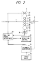
- Fig. 2 shows a cold rolling mill shown in Fig. 1 and its control system; and
- Fig. 3 is a schematic view of a coating equipment of the second embodiment according to the present invention.
- Hereinafter, preferred embodiments of the present invention will be described with reference to the accompanying drawings.
- First of all, the first embodiment of the present invention, a coating strip of cold rolling, will be explained with reference to Figs. 1 and 2.
- Referring to Fig. 1, the coating equipment of this embodiment comprises
uncoilers hot coils welder 2 for joining strips, a bridle roll No.1 3, anentry looper 4, apickling tank 5, a bridle roll No.2 6, acold rolling mill 7, atension meter 8, athickness gauge 9, a bridle roll No.3 10, a furnace entryside deflector roll 11, a heating anddeoxidizing furnace 12, acoating pot 13 having asink roll 14 and acoating bath 16, acoating thickness controller 15, adeflector roller 17, a bridle roll No.4 18, askin pass mill 19, a deflector roller 20, anexit looper 21, a bridle roll No.5 22, anexit shear 23 and auncoiler 51 of aproduct coil 24, that are sequentially disposed in this order. - The
cold rolling mill 7 is interposed between thepickling tank 5 and the heating anddeoxidizing furnace 12. Onecold rolling mill 7 is used in this embodiment, and effects rolling at a draft of 20 to 50% in the case of production of thin coated strips. Thecold rolling mill 7 is kept open for empty pass in the case of the production of thick coated strips. - The
cold rolling mill 7 desirably is small in size but can attain a high draft, and has the function of not deteriorating the shape of the strip even when the draft is changed. The most suitable rolling mill for this purpose is HC-MILL comprising a work roll to which a bending force is applied and a 6-high mill having an intermediate roll capable of shifting in the axial direction. Furthermore, UC-MILL equipped with means for imparting bending force to the intermediate roll, too, is most suitable. These rolling mills can easily attain a draft of 50% by one pass and have the function of stably maintaining the flat strip shape even when the draft, that is, the rolling force, is changed. - Fig. 2 shows the
cold rolling mill 7 and its control system. In this embodiment, thecold rolling mill 7 is for example, HC-MILL, which includes back-up rolls 26, 26,intermediate rolls - In the
cold rolling mill 7, the thickness of the rollingmaterial 1 is subjected to feedback control in the same way as in the conventional thickness control method. In other words, thethickness gauge 9 is disposed on the downstream side of thecold rolling mill 7 so that the thickness of the rollingmaterial 1 rolled between the work rolls 28, 28 of thecold rolling mill 7 can be measured by thethickness gauge 9. The thickness measurement value ha measured by thethickness gauge 9 is compared with a thickness control target value hAGC from a thicknesscontrol target setter 34 by athickness comparator 33, and a signal representing this difference is sent to a rollingforce control equipment 32. The thickness difference signal from thethickness comparator 33, a rolling force signal in thecold rolling mill 7 from aload cell 25 and a rolling position signal from a rollingposition sensor 30 are inputted to the rollingforce control equipment 32, which outputs a rolling force signal to a hydraulicroll positioning device 31. When the thickness control target value is set to be greater than the thickness, the rolling force becomes zero, and the rolling mill can be kept open for empty pass. - Fig. 3 is a schematic view of the second embodiment, wherein the present invention is applied to the production of coating strip of cold rolling. This embodiment is directed to produce thinner coating strips, mainly coating strips of cold rolling.
- The construction of the coating equipment shown in this drawing is the same as that of the coating equipment shown in Fig. 1. However, three, rolling mills No.1 to No.3 7A, 7B and 7C are disposed as the cold rolling mills interposed between the
pickling tank 5 and the heating anddeoxidizing furnace 12, and this rolling equipment can produce hot coils having a thickness of about 1.8 mm to coating strips having a minimum thickness of 0.27 mm.Tension meters mills - To exchange the work roll of the rolling mill No.2 7B in the embodiment shown in Fig. 3, the thickness is set to a value so that the strip can be rolled by only the rolling mill No.1 7A and the rolling mill No.3 7C, and the work roll is then exchanged while the roll gap of the rolling mill No.2 7B is kept open. After a new roll is mounted, rolling is carried out using the three
rolling mills tension meters - The embodiments shown in Figs. 1 to 3 can first provide an economical coating strip in place of a coating strip of hot rolling. The minimum thickness which can be produced on the commercial basis by an orindary hot strip mill is 1.2 mm, but troubles are frequently occur due to rough surface of the rolls under a high pressure, bending and breakage of the strip at the time of threading and trailing-off, etc. Accordingly, rolling must be done with utmost care and quite naturally, the production cost becomes very high. Though there is a demand for further reduction of the thickness, the operation becomes all the more difficult. Even when hot rolling of a thickness of 1.0 mm can be done, the productivity drops to 1/2 in comparison with rolling of 2.0 mm and the scale loss rises from 1.5% to 3%, so that the loss of coil becomes ¥900/ton.
- On the other hand, energy required for cold-rolling a strip from 2.0 mm to 1.0 mm is 15 KWhr/ton and is about ¥300, and saving of ¥600/ton can be attained.
- To ensure a minimum thickness of 0.27 mm as in ordinary production lines of a coating strip of cold rolling, three cold rolling mills must be provided using a 1.8 mm-thick hot rolled strip as its material. In this embodiment, however, the
pickling tank 5, thecold rolling mills coating pot 13 are disposed in series, and redundant installation of feeders, winding machines and welders for joining the strips as in the ordinary independent pickling line, the cold rolling mill and the coating line can be avoided. Accordingly, the installation cost becomes lower, and since two coil-transfer-operations between the lines can be eliminated, saving of ¥5,000/ton on an average can be attained. - Furthermore, the number of operators necessary for the operations can be reduced. One-stand reverse cold mills are generally used for the line described above with the exception of integrated steelworks of major steel manufactures. As to this example, 21 operators in total, are necessary, that is, two for the pickling line, two for the rolling mils, three for the coating line, i.e., seven operators, on three shifts, (7 × 3 = 21). By adopting the through-process line of this embodiment, on the other hand, the number of operators can be reduced to 4 × 3 = 12, and line operators can be saved. In connection with the production yield, unrolled portions are left at the leading and trailing end portions of the coil in the reverse cold rolling mill, and the yield is generally 3%. In this embodiment, the unrolled portions can be made zero. Assuming the saving of this loss is ¥1,800 when the price is 60,000 yen/ton and production output is 200,000 tons/annum, an increase of ¥360,000,000/annum of revenue can be gained.
- Further, the rolling speed of 180 m/min of the cold rolling mill 7 (or 7A, 7B, 7C) is lower than those of ordinary reverse rolling mills (1,000 to 1,400 m/min) and the work roll diameter can be reduced to as small as 200 to 300 mm in comparison with the diameters of the ordinary rolls of 400 to 500 mm. Accordingly, the rolling force can be reduced and the roll can be small. Since the right and left winding machines and the feeder of the coil which are necessary for the reverse rolling mill are not necessary, even three sets of the rolling mill can roll strips at substantially the same installation cost of the high speed reverse rolling mill.
- It is conceivable to dispose a looper so as not to stop the coating line at the time of the exchange of the roll. In the embodiment shown in Fig. 3, however, the gaps of two stands among the three are set to a value with which rolling can be done at the time of the exchange of the roll, and the roll exchange is carried out while the stand to be exchange is brought into the empty pass state. Accordingly, the looper for this purpose is not necessary.
- As described above, according to the present invention, a variety of coating strips required by users can be promptly produced at costs approximate to those of hot rolled coating material without carrying out thin strip rolling which cannot be rolled easily by a hot strip mill.
Claims (7)
- A coating equipment including a hot rolling coil uncoiler (50a, 50b), a strip welder (2), a pickling equipment (5), a heating and deoxidizing furnace (12), a coating pot (13), and a coiler (51) sequentially disposed in this order, for applying coating to the strip surface using a hot rolling strip coil (1a, 1b) as a material,
characterized in that
at least one stand of cold rolling mill (7) is interposed between said pickling tank (5) and said heating and deoxidizing furnace (12) so that said hot rolling strip coil (1a, 1b) can be rolled in one pass. - A coating equipment according to claim 1, wherein said cold rolling mill (7) can selectively effect cold rolling or empty pass of said hot rolling strip coil (1a, 1b).
- A coating equipment according to claim 1 or 2, wherein said at least one stand of cold rolling mill (7) comprises a plurality of cold rolling mills (7A-7C) arranged in a tandem arrangement, and said hot rolling strip coil is rolled by selectively using said cold rolling mills of a plurality of stands.
- A method of coating a hot rolling strip including the steps of uncoiling the strip in an uncoiler (50a, 50b), welding the strip in a strip welder (2), pickling the strip in a pickling equipment (5), heating and deoxidizing the strip in a furnace (12), coating the strip in a coating pot (13) and coiling up the strip in a coil winding machine (51) sequentially disposed in this order, for applying a coating to the hot rolling strip surface, characterized by selectively effecting one of the following first and second steps:
feeding the strip through at least one stand of cold rolling mill (7) disposed between said pickling equipment (5) and said furnace (12),
opening said cold rolling mill (7) so as to effect empty pass in accordance with the kind of coating product, and applying coating directly in said pickling equipment (5); or
closing said cold rolling mill (7) for cold rolling the strip and effecting coating treatment in said pickling equipment after cold rolling is carried out by said cold rolling mill. - Method according to claim 4, wherein said first step is selected to coat a coating product having a large thickness, and said second step is selected to coat a coating product having a small thickness.
- Method according to claim 4, wherein, when the thicknesses of materials of hot rolling strip coils are the same, coating products having various thicknesses are produced by selecting one of said first step and said second step, and by changing the draft of said cold rolling mill in said second step.
- Method according to claims 4 to 6, wherein the strip is cold rolled in one or more cold rolling stands (7A to 7C) in dependence of the kind of the material, the thickness and the shape of the strip.
Applications Claiming Priority (2)
| Application Number | Priority Date | Filing Date | Title |
|---|---|---|---|
| JP38135/93 | 1993-02-26 | ||
| JP5038135A JP2799275B2 (en) | 1993-02-26 | 1993-02-26 | Plating equipment and its operation method |
Publications (2)
| Publication Number | Publication Date |
|---|---|
| EP0613736A1 true EP0613736A1 (en) | 1994-09-07 |
| EP0613736B1 EP0613736B1 (en) | 1996-12-04 |
Family
ID=12516992
Family Applications (1)
| Application Number | Title | Priority Date | Filing Date |
|---|---|---|---|
| EP94101902A Revoked EP0613736B1 (en) | 1993-02-26 | 1994-02-08 | Coating system for coating a hot rolled strip material |
Country Status (5)
| Country | Link |
|---|---|
| US (1) | US5463801A (en) |
| EP (1) | EP0613736B1 (en) |
| JP (1) | JP2799275B2 (en) |
| KR (1) | KR100307110B1 (en) |
| DE (1) | DE69401015T2 (en) |
Cited By (9)
| Publication number | Priority date | Publication date | Assignee | Title |
|---|---|---|---|---|
| EP0863222A1 (en) * | 1997-03-04 | 1998-09-09 | Sms Schloemann-Siemag Aktiengesellschaft | Method and device for manufacturing metal strip |
| WO2001064970A2 (en) * | 2000-03-01 | 2001-09-07 | Sms Demag Aktiengesellschaft | Method and installation for hot dip coating metal strips |
| DE10109056B4 (en) * | 2001-02-24 | 2010-03-11 | Sms Siemag Aktiengesellschaft | Plant and method for treating a metal strip or sheet |
| CN102239028A (en) * | 2008-12-05 | 2011-11-09 | 蒂森克虏伯激光拼焊板有限公司 | Method for producing tailor-made sheet strips |
| CN103464505A (en) * | 2013-09-06 | 2013-12-25 | 武汉钢铁(集团)公司 | Device and method for producing high-frequency roll welding multilayer composite plate |
| CN104607465A (en) * | 2015-01-30 | 2015-05-13 | 河北钢铁股份有限公司邯郸分公司 | Pickling-rolling process of thin-gauge household appliance steel of 300 mu]m and below |
| WO2015110490A1 (en) * | 2014-01-22 | 2015-07-30 | Sms Group Gmbh | Method and system for hot-dip coating hot-rolled steel strips |
| EP3296032A1 (en) * | 2016-09-19 | 2018-03-21 | Yieh United Steel Corp. | Duplex cold rolling line |
| CN111515245A (en) * | 2020-05-09 | 2020-08-11 | 广东誉嘉智能装备有限公司 | Continuous pair roller production line for lithium ion batteries |
Families Citing this family (16)
| Publication number | Priority date | Publication date | Assignee | Title |
|---|---|---|---|---|
| US5767475A (en) * | 1995-09-29 | 1998-06-16 | Kyoei Steel Co., Ltd. | Hot rolling method |
| JPH09141304A (en) * | 1995-11-21 | 1997-06-03 | Kyoei Seiko Kk | Hot rolling process |
| KR100368253B1 (en) | 1997-12-09 | 2003-03-15 | 주식회사 포스코 | Method for manufacturing hot rolled strip by mini mill process |
| JP2965969B1 (en) * | 1998-07-17 | 1999-10-18 | 川崎重工業株式会社 | Continuous plating method for steel sheet |
| FR2807957B1 (en) * | 2000-04-21 | 2002-08-02 | Vai Clecim | METHOD AND INSTALLATION FOR COLD ROLLING |
| US6564702B1 (en) * | 2000-09-05 | 2003-05-20 | Rockwell Automation Technologies, Inc. | System for measuring material in a press |
| US6598287B1 (en) | 2002-01-24 | 2003-07-29 | Western Tube & Conduit Corporation | Apparatus and method for sizing a galvanized tube |
| DE102004023886B4 (en) * | 2004-05-12 | 2007-04-12 | Muhr Und Bender Kg | Method and device for finishing flexibly rolled strip material |
| DE102005013103A1 (en) * | 2005-03-18 | 2006-09-28 | Sms Demag Ag | Controlled thickness reduction in hot-dip coated hot rolled steel strip and equipment used in this case |
| JP2009524526A (en) * | 2006-01-26 | 2009-07-02 | アルヴェーディ、ジョヴァンニ | Steel plate manufacturing process suitable for anti-oxidation surface coating |
| DE102007013739B3 (en) * | 2007-03-22 | 2008-09-04 | Voestalpine Stahl Gmbh | Flexible rolling process to manufacture sheet metal component after hot or cold dipping and further mechanical and/or chemical treatment |
| JP2011092834A (en) * | 2009-10-28 | 2011-05-12 | Jfe Steel Corp | Apparatus and method of coating metallic strip |
| US9687893B2 (en) * | 2013-04-01 | 2017-06-27 | Hitachi Metals, Ltd. | Manufacturing method of martensite-based stainless steel for edged tools |
| MX2016012711A (en) * | 2014-03-31 | 2017-03-31 | Primetals Technologies Austria GmbH | Equipment and process for the pickling and metallic coating of a metal strip. |
| JP6476227B2 (en) * | 2017-03-31 | 2019-02-27 | Jx金属株式会社 | Copper or copper alloy strip, traverse coil and manufacturing method thereof |
| US20230295760A1 (en) * | 2020-09-30 | 2023-09-21 | Nippon Steel Corporation | High-strength steel sheet |
Citations (4)
| Publication number | Priority date | Publication date | Assignee | Title |
|---|---|---|---|---|
| JPS56122611A (en) * | 1980-03-03 | 1981-09-26 | Kawasaki Steel Corp | Method and apparatus for manufacture cold rolled sheet product |
| JPS5758905A (en) * | 1980-09-26 | 1982-04-09 | Nippon Steel Corp | Continuous processing lines for steel strip |
| JPS5764403A (en) * | 1980-10-09 | 1982-04-19 | Nippon Kokan Kk <Nkk> | Cold rolling method in continuous process line |
| JPH01208445A (en) * | 1988-02-15 | 1989-08-22 | Kawasaki Steel Corp | Continuous molten metal plating apparatus for steel strip |
Family Cites Families (8)
| Publication number | Priority date | Publication date | Assignee | Title |
|---|---|---|---|---|
| CA702699A (en) * | 1965-01-26 | M. Bernick Leslie | Process for producing thin gauge metal plate | |
| SU590034A1 (en) * | 1976-09-13 | 1978-01-30 | Уральский научно-исследовательский институт трубной промышленности | Method of manufacturing metal tubes with corrosion-proof coating |
| DE2837847C2 (en) * | 1977-08-31 | 1985-04-25 | Hitachi, Ltd., Tokio/Tokyo | Coating press for making clad wires |
| US4885042A (en) * | 1987-05-22 | 1989-12-05 | Kawasaki Steel Corp. | Method and apparatus for preliminary treatment of stainless steel for cold rolling |
| NL8702050A (en) * | 1987-09-01 | 1989-04-03 | Hoogovens Groep Bv | METHOD AND APPARATUS FOR THE MANUFACTURE OF TIRE-DEFORMING STEEL WITH GOOD MECHANICAL AND SURFACE PROPERTIES. |
| US5174822A (en) * | 1991-01-03 | 1992-12-29 | National Steel Corporation | Steel strip annealing and coating apparatus |
| EP0541817A4 (en) * | 1991-04-17 | 1995-02-22 | Magnitogorsk Metall Kom | Technological line for production of metal strip and a transporting device therefor |
| US5197179A (en) * | 1991-04-18 | 1993-03-30 | T. Sendzimir, Inc. | Means and a method of improving the quality of cold rolled stainless steel strip |
-
1993
- 1993-02-26 JP JP5038135A patent/JP2799275B2/en not_active Expired - Lifetime
-
1994
- 1994-02-08 DE DE69401015T patent/DE69401015T2/en not_active Revoked
- 1994-02-08 EP EP94101902A patent/EP0613736B1/en not_active Revoked
- 1994-02-23 US US08/200,668 patent/US5463801A/en not_active Expired - Fee Related
- 1994-02-25 KR KR1019940003415A patent/KR100307110B1/en not_active IP Right Cessation
Patent Citations (4)
| Publication number | Priority date | Publication date | Assignee | Title |
|---|---|---|---|---|
| JPS56122611A (en) * | 1980-03-03 | 1981-09-26 | Kawasaki Steel Corp | Method and apparatus for manufacture cold rolled sheet product |
| JPS5758905A (en) * | 1980-09-26 | 1982-04-09 | Nippon Steel Corp | Continuous processing lines for steel strip |
| JPS5764403A (en) * | 1980-10-09 | 1982-04-19 | Nippon Kokan Kk <Nkk> | Cold rolling method in continuous process line |
| JPH01208445A (en) * | 1988-02-15 | 1989-08-22 | Kawasaki Steel Corp | Continuous molten metal plating apparatus for steel strip |
Non-Patent Citations (4)
| Title |
|---|
| PATENT ABSTRACTS OF JAPAN vol. 13, no. 516 (C - 656) 17 November 1989 (1989-11-17) * |
| PATENT ABSTRACTS OF JAPAN vol. 5, no. 206 (M - 104) 26 December 1981 (1981-12-26) * |
| PATENT ABSTRACTS OF JAPAN vol. 6, no. 134 (M - 144) 21 July 1982 (1982-07-21) * |
| PATENT ABSTRACTS OF JAPAN vol. 6, no. 142 (M - 146) 31 July 1982 (1982-07-31) * |
Cited By (13)
| Publication number | Priority date | Publication date | Assignee | Title |
|---|---|---|---|---|
| EP0863222A1 (en) * | 1997-03-04 | 1998-09-09 | Sms Schloemann-Siemag Aktiengesellschaft | Method and device for manufacturing metal strip |
| WO2001064970A2 (en) * | 2000-03-01 | 2001-09-07 | Sms Demag Aktiengesellschaft | Method and installation for hot dip coating metal strips |
| WO2001064970A3 (en) * | 2000-03-01 | 2001-12-20 | Sms Demag Ag | Method and installation for hot dip coating metal strips |
| US6811827B2 (en) | 2000-03-01 | 2004-11-02 | Sms Demag Ag | Method and installation for hot dip coating metal strips |
| DE10109056B4 (en) * | 2001-02-24 | 2010-03-11 | Sms Siemag Aktiengesellschaft | Plant and method for treating a metal strip or sheet |
| CN102239028A (en) * | 2008-12-05 | 2011-11-09 | 蒂森克虏伯激光拼焊板有限公司 | Method for producing tailor-made sheet strips |
| CN103464505A (en) * | 2013-09-06 | 2013-12-25 | 武汉钢铁(集团)公司 | Device and method for producing high-frequency roll welding multilayer composite plate |
| CN103464505B (en) * | 2013-09-06 | 2015-06-17 | 武汉钢铁(集团)公司 | Device and method for producing high-frequency roll welding multilayer composite plate |
| WO2015110490A1 (en) * | 2014-01-22 | 2015-07-30 | Sms Group Gmbh | Method and system for hot-dip coating hot-rolled steel strips |
| CN104607465A (en) * | 2015-01-30 | 2015-05-13 | 河北钢铁股份有限公司邯郸分公司 | Pickling-rolling process of thin-gauge household appliance steel of 300 mu]m and below |
| EP3296032A1 (en) * | 2016-09-19 | 2018-03-21 | Yieh United Steel Corp. | Duplex cold rolling line |
| CN107838193A (en) * | 2016-09-19 | 2018-03-27 | 烨联钢铁股份有限公司 | Combined type cold rolling line |
| CN111515245A (en) * | 2020-05-09 | 2020-08-11 | 广东誉嘉智能装备有限公司 | Continuous pair roller production line for lithium ion batteries |
Also Published As
| Publication number | Publication date |
|---|---|
| JP2799275B2 (en) | 1998-09-17 |
| US5463801A (en) | 1995-11-07 |
| JPH06248407A (en) | 1994-09-06 |
| EP0613736B1 (en) | 1996-12-04 |
| DE69401015T2 (en) | 1997-04-03 |
| DE69401015D1 (en) | 1997-01-16 |
| KR940019368A (en) | 1994-09-14 |
| KR100307110B1 (en) | 2002-01-09 |
Similar Documents
| Publication | Publication Date | Title |
|---|---|---|
| US5463801A (en) | Rolling mill coating equipment | |
| EP2087948B1 (en) | Cold rolled material production equipment and cold rolling method | |
| EP0615793B2 (en) | Hot rolling method | |
| EP2514534B1 (en) | Equipment for manufacturing a cold-rolled material, and cold-rolling method | |
| EP3595822B1 (en) | Combined continuous casting and metal strip hot-rolling plant | |
| EP3595821B1 (en) | Combined continuous casting and metal strip hot-rolling plant | |
| KR20020079921A (en) | Hot rolling method and hot rolling line | |
| JPS61126908A (en) | Enhancement of productivity of reversal plate rolling machine | |
| CN111182978B (en) | Multipurpose rolling equipment | |
| US6463777B1 (en) | Method for the continuous production of a metal strip | |
| RU2217247C2 (en) | Universal casting and rolling mill | |
| CN114101334A (en) | Process for eliminating thin hot-rolled strip steel from winding pinch roll of coiler and control method | |
| JPH0679303A (en) | Method and equipment for descaling and cold rolling | |
| KR100435435B1 (en) | Hot strip mill facility combined with extra thin strip mill and method for manufacturing extra thin hot strip by using it | |
| US6035684A (en) | Method of rolling strip, particularly metal strip | |
| FUKUDA | Progress of rolling technologies in Japan | |
| JP3553648B2 (en) | Metal strip manufacturing method | |
| JP3385684B2 (en) | Hot rolling equipment and hot rolling method | |
| SUZUKI | Recent Progress in the Rolling Mills-Part I | |
| JP4211123B2 (en) | Continuous hot rolling apparatus and hot rolled coil manufacturing method | |
| JP3218598B2 (en) | Thickness control method for leading and trailing edges of material in tandem rolling mill | |
| Djumlija et al. | Mill modernisation for improvements in strip quality and yield | |
| JPS5945443B2 (en) | Cold rolling method in continuous process line | |
| Earnshaw | Cold rolling of sheet and strip: steel | |
| JPS61283476A (en) | Method and equipment for producing clad steel sheet |
Legal Events
| Date | Code | Title | Description |
|---|---|---|---|
| PUAI | Public reference made under article 153(3) epc to a published international application that has entered the european phase |
Free format text: ORIGINAL CODE: 0009012 |
|
| 17P | Request for examination filed |
Effective date: 19940713 |
|
| AK | Designated contracting states |
Kind code of ref document: A1 Designated state(s): DE GB |
|
| 17Q | First examination report despatched |
Effective date: 19950502 |
|
| GRAG | Despatch of communication of intention to grant |
Free format text: ORIGINAL CODE: EPIDOS AGRA |
|
| GRAH | Despatch of communication of intention to grant a patent |
Free format text: ORIGINAL CODE: EPIDOS IGRA |
|
| GRAH | Despatch of communication of intention to grant a patent |
Free format text: ORIGINAL CODE: EPIDOS IGRA |
|
| GRAA | (expected) grant |
Free format text: ORIGINAL CODE: 0009210 |
|
| AK | Designated contracting states |
Kind code of ref document: B1 Designated state(s): DE GB |
|
| REF | Corresponds to: |
Ref document number: 69401015 Country of ref document: DE Date of ref document: 19970116 |
|
| PLBI | Opposition filed |
Free format text: ORIGINAL CODE: 0009260 |
|
| PLBQ | Unpublished change to opponent data |
Free format text: ORIGINAL CODE: EPIDOS OPPO |
|
| PLAV | Examination of admissibility of opposition |
Free format text: ORIGINAL CODE: EPIDOS OPEX |
|
| PLBF | Reply of patent proprietor to notice(s) of opposition |
Free format text: ORIGINAL CODE: EPIDOS OBSO |
|
| 26 | Opposition filed |
Opponent name: SMS SCHLOEMANN-SIEMAG AG Effective date: 19970903 |
|
| PGFP | Annual fee paid to national office [announced via postgrant information from national office to epo] |
Ref country code: GB Payment date: 19980129 Year of fee payment: 5 |
|
| PLBF | Reply of patent proprietor to notice(s) of opposition |
Free format text: ORIGINAL CODE: EPIDOS OBSO |
|
| PGFP | Annual fee paid to national office [announced via postgrant information from national office to epo] |
Ref country code: DE Payment date: 19980424 Year of fee payment: 5 |
|
| RDAH | Patent revoked |
Free format text: ORIGINAL CODE: EPIDOS REVO |
|
| RDAG | Patent revoked |
Free format text: ORIGINAL CODE: 0009271 |
|
| STAA | Information on the status of an ep patent application or granted ep patent |
Free format text: STATUS: PATENT REVOKED |
|
| 27W | Patent revoked |
Effective date: 19980711 |
|
| GBPR | Gb: patent revoked under art. 102 of the ep convention designating the uk as contracting state |
Free format text: 980711 |