WO2011068048A1 - 媒体処理装置 - Google Patents
媒体処理装置 Download PDFInfo
- Publication number
- WO2011068048A1 WO2011068048A1 PCT/JP2010/070737 JP2010070737W WO2011068048A1 WO 2011068048 A1 WO2011068048 A1 WO 2011068048A1 JP 2010070737 W JP2010070737 W JP 2010070737W WO 2011068048 A1 WO2011068048 A1 WO 2011068048A1
- Authority
- WO
- WIPO (PCT)
- Prior art keywords
- medium
- cassette
- transport path
- frame
- medium storage
- Prior art date
- Legal status (The legal status is an assumption and is not a legal conclusion. Google has not performed a legal analysis and makes no representation as to the accuracy of the status listed.)
- Ceased
Links
Images


Classifications
-
- B—PERFORMING OPERATIONS; TRANSPORTING
- B65—CONVEYING; PACKING; STORING; HANDLING THIN OR FILAMENTARY MATERIAL
- B65H—HANDLING THIN OR FILAMENTARY MATERIAL, e.g. SHEETS, WEBS, CABLES
- B65H1/00—Supports or magazines for piles from which articles are to be separated
- B65H1/28—Supports or magazines for piles from which articles are to be separated compartmented to receive piles side-by-side
-
- B—PERFORMING OPERATIONS; TRANSPORTING
- B65—CONVEYING; PACKING; STORING; HANDLING THIN OR FILAMENTARY MATERIAL
- B65H—HANDLING THIN OR FILAMENTARY MATERIAL, e.g. SHEETS, WEBS, CABLES
- B65H1/00—Supports or magazines for piles from which articles are to be separated
- B65H1/26—Supports or magazines for piles from which articles are to be separated with auxiliary supports to facilitate introduction or renewal of the pile
- B65H1/266—Support fully or partially removable from the handling machine, e.g. cassette, drawer
-
- B—PERFORMING OPERATIONS; TRANSPORTING
- B65—CONVEYING; PACKING; STORING; HANDLING THIN OR FILAMENTARY MATERIAL
- B65H—HANDLING THIN OR FILAMENTARY MATERIAL, e.g. SHEETS, WEBS, CABLES
- B65H31/00—Pile receivers
- B65H31/22—Pile receivers removable or interchangeable
-
- B—PERFORMING OPERATIONS; TRANSPORTING
- B65—CONVEYING; PACKING; STORING; HANDLING THIN OR FILAMENTARY MATERIAL
- B65H—HANDLING THIN OR FILAMENTARY MATERIAL, e.g. SHEETS, WEBS, CABLES
- B65H31/00—Pile receivers
- B65H31/24—Pile receivers multiple or compartmented, e.d. for alternate, programmed, or selective filling
-
- G—PHYSICS
- G07—CHECKING-DEVICES
- G07D—HANDLING OF COINS OR VALUABLE PAPERS, e.g. TESTING, SORTING BY DENOMINATIONS, COUNTING, DISPENSING, CHANGING OR DEPOSITING
- G07D11/00—Devices accepting coins; Devices accepting, dispensing, sorting or counting valuable papers
- G07D11/10—Mechanical details
- G07D11/12—Containers for valuable papers
-
- G—PHYSICS
- G07—CHECKING-DEVICES
- G07D—HANDLING OF COINS OR VALUABLE PAPERS, e.g. TESTING, SORTING BY DENOMINATIONS, COUNTING, DISPENSING, CHANGING OR DEPOSITING
- G07D11/00—Devices accepting coins; Devices accepting, dispensing, sorting or counting valuable papers
- G07D11/40—Device architecture, e.g. modular construction
-
- B—PERFORMING OPERATIONS; TRANSPORTING
- B65—CONVEYING; PACKING; STORING; HANDLING THIN OR FILAMENTARY MATERIAL
- B65H—HANDLING THIN OR FILAMENTARY MATERIAL, e.g. SHEETS, WEBS, CABLES
- B65H2402/00—Constructional details of the handling apparatus
- B65H2402/40—Details of frames, housings or mountings of the whole handling apparatus
- B65H2402/44—Housings
- B65H2402/441—Housings movable for facilitating access to area inside the housing, e.g. pivoting or sliding
-
- B—PERFORMING OPERATIONS; TRANSPORTING
- B65—CONVEYING; PACKING; STORING; HANDLING THIN OR FILAMENTARY MATERIAL
- B65H—HANDLING THIN OR FILAMENTARY MATERIAL, e.g. SHEETS, WEBS, CABLES
- B65H2402/00—Constructional details of the handling apparatus
- B65H2402/40—Details of frames, housings or mountings of the whole handling apparatus
- B65H2402/45—Doors
-
- B—PERFORMING OPERATIONS; TRANSPORTING
- B65—CONVEYING; PACKING; STORING; HANDLING THIN OR FILAMENTARY MATERIAL
- B65H—HANDLING THIN OR FILAMENTARY MATERIAL, e.g. SHEETS, WEBS, CABLES
- B65H2402/00—Constructional details of the handling apparatus
- B65H2402/60—Coupling, adapter or locking means
-
- B—PERFORMING OPERATIONS; TRANSPORTING
- B65—CONVEYING; PACKING; STORING; HANDLING THIN OR FILAMENTARY MATERIAL
- B65H—HANDLING THIN OR FILAMENTARY MATERIAL, e.g. SHEETS, WEBS, CABLES
- B65H2405/00—Parts for holding the handled material
- B65H2405/10—Cassettes, holders, bins, decks, trays, supports or magazines for sheets stacked substantially horizontally
- B65H2405/11—Parts and details thereof
- B65H2405/114—Side, i.e. portion parallel to the feeding / delivering direction
-
- B—PERFORMING OPERATIONS; TRANSPORTING
- B65—CONVEYING; PACKING; STORING; HANDLING THIN OR FILAMENTARY MATERIAL
- B65H—HANDLING THIN OR FILAMENTARY MATERIAL, e.g. SHEETS, WEBS, CABLES
- B65H2405/00—Parts for holding the handled material
- B65H2405/30—Other features of supports for sheets
- B65H2405/31—Supports for sheets fully removable from the handling machine, e.g. cassette
- B65H2405/313—Supports for sheets fully removable from the handling machine, e.g. cassette with integrated handling means, e.g. separating means
-
- B—PERFORMING OPERATIONS; TRANSPORTING
- B65—CONVEYING; PACKING; STORING; HANDLING THIN OR FILAMENTARY MATERIAL
- B65H—HANDLING THIN OR FILAMENTARY MATERIAL, e.g. SHEETS, WEBS, CABLES
- B65H2405/00—Parts for holding the handled material
- B65H2405/30—Other features of supports for sheets
- B65H2405/33—Compartmented support
- B65H2405/331—Juxtaposed compartments
- B65H2405/3311—Juxtaposed compartments for storing articles horizontally or slightly inclined
-
- B—PERFORMING OPERATIONS; TRANSPORTING
- B65—CONVEYING; PACKING; STORING; HANDLING THIN OR FILAMENTARY MATERIAL
- B65H—HANDLING THIN OR FILAMENTARY MATERIAL, e.g. SHEETS, WEBS, CABLES
- B65H2601/00—Problem to be solved or advantage achieved
- B65H2601/30—Facilitating or easing
- B65H2601/32—Facilitating or easing entities relating to handling machine
- B65H2601/324—Removability or inter-changeability of machine parts, e.g. for maintenance
-
- B—PERFORMING OPERATIONS; TRANSPORTING
- B65—CONVEYING; PACKING; STORING; HANDLING THIN OR FILAMENTARY MATERIAL
- B65H—HANDLING THIN OR FILAMENTARY MATERIAL, e.g. SHEETS, WEBS, CABLES
- B65H2701/00—Handled material; Storage means
- B65H2701/10—Handled articles or webs
- B65H2701/19—Specific article or web
- B65H2701/1912—Banknotes, bills and cheques or the like
Definitions
- the present invention relates to a medium processing apparatus such as a banknote depositing / dispensing machine, and more particularly to a medium processing apparatus including a removable medium storage cassette for storing a medium such as a banknote.
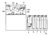
- FIG. 14 is a side view showing the internal structure of the conventional apparatus disclosed in Japanese Patent Laid-Open No. 2009-098835
- FIG. 15 is a side view showing a state in which the bill storage cassette is pulled out from the apparatus.
- this apparatus has a customer service section 31, a discrimination section 32, a temporary storage section 33, transport paths 34 a, 34 b, 34 c, 34 d, 34 e, and a distribution path (distribution transport path) at the top. ) 3, and a plurality of banknote storage cassettes (medium storage cassettes) 5 to 8 and a medium storage cassette (stacker integrated type) 9 are arranged in a row from the front side of the apparatus toward the back side. It is loaded.
- the transport paths 34a, 34b, and 34c are provided so as to form a loop-shaped path that returns from the customer service section 31 to the customer service section 31 via the discrimination section 32 and the temporary storage section 33, and the transport path 3 includes the bill storage cassettes 5 to 8.
- the conveying path 34d is arranged in a straight line along the row of the medium storage cassettes 9, and the conveying path 34d is connected to the conveying path 34a and the conveying path 3 at the front side position and the rear side position of the discrimination section 32, and the conveying path 34e. Is provided so as to connect the conveyance path 34 b and the conveyance path 3.
- banknote (medium) deposit processing and withdrawal processing are performed as follows.
- deposit processing banknotes put into the customer service section 31 by a customer are separated one by one and transported to a discrimination section 32 through a transport path 34a. Is detected.
- the banknotes that can be deposited are transported to the temporary storage unit 33 by the transport path 34b and temporarily stored, and the banknotes whose denomination or abnormality is detected but cannot be deposited are transported to the customer service section 31 by the transport paths 34b and 34c. And returned to the customer.
- the amount of the identified banknotes is displayed on a display unit (not shown).
- the customer confirms the amount and approves the transaction the amount is temporarily held in the temporary holding unit 33.
- the banknotes are fed one by one and fed back to the discrimination unit 32 through the conveyance path 34b, and the discrimination unit 32 performs the denomination again.
- the banknotes after the discrimination are sent from the transport path 34a to the transport path 3 through the transport path 34d, sorted by the sorting section of the transport path 3 according to the type of discrimination, and stored in the banknote storage cassettes 5 to 8 in denominations. .
- banknotes are paid out from at least one of the banknote storage cassettes 5 to 8 according to the denomination and the amount of money inputted by the customer through an operation unit (not shown), and the fed banknotes are transported in the transport path 3 and transport path 34d. Then, it is conveyed to the discrimination unit 32 by the conveyance path 34a. Then, after the discrimination and counting of the denominations and the like are performed by the discrimination unit 32, the banknotes are transported and accumulated in the customer service unit 31 through the transport paths 34b and 34c, and the banknotes of the denomination and amount input by the customer are received. When accumulated in the unit 31, the shutter of the customer service unit 31 is opened and paid out to the customer.
- a box-shaped cassette loading frame 35 having an upper surface side as an opening surface is provided.
- a plurality of banknote storage cassettes (medium storage cassettes) 5 to 8 and medium storage are provided in the cassette loading frame 35.
- Cassette 9 is loaded.
- the upper and lower parts are divided by a banknote delivery section (medium delivery section) between the transport path 3 and each of the cassettes 5 to 9 inside the apparatus, and the cassettes 5 to 9 are box-shaped with the upper surface side as an opening surface.
- the cassettes 5 to 9 can be taken out from the cassette loading frame 35 by being lifted upward.
- each of the cassettes 5 to 9 is mounted inside the apparatus together with the cassette loading frame 35, it is necessary to make each banknote delivery section coincide with the banknote delivery section on the transport path 3 side. h is set as high as possible, and the cassettes 5 to 9 are positioned by a positioning unit (not shown) on the upper end side thereof, thereby suppressing the shake of the cassettes 5 to 9.
- the cassette loading frame since the cassette loading frame has a large height, in order to take out the cassettes 5 to 9 from the cassette loading frame 35, the heavy cassettes 5 to 9 are raised upward. There is a problem in that it has to be lifted, the operability is very poor, and there is a risk of dropping when taking out each cassette 5-9.
- the positioning of the cassettes 5 to 9 is performed on the upper portion of the cassette loading frame 35.
- the cassettes 5 to 9 are shaken, and when the cassettes 5 to 9 are mounted in the apparatus together with the cassette loading frame 35, A deviation occurs between the banknote delivery section of the conveyance path 3 and the banknote delivery sections of the cassettes 5 to 9, thereby causing banknote jam (medium jam).
- This invention makes it a subject to solve such a problem.
- the present invention conveys a plurality of medium storage cassettes for storing media and the medium stored in each of the medium storage cassettes, distributes the conveyed medium to each of the medium storage cassettes, and removes from each medium storage cassette.
- the cassette loading frame has a height of a side plate on the cassette operation side that is less than half of the height of each medium storage cassette. It was set as the structure which provided the some partition plate which partitions off each cassette accommodation position.
- the transport path is disposed in the transport path frame so that the medium delivery section is exposed, and the transport path frame is attached to the cassette loading frame so as to be opened and closed.
- the transport path frame is structured to be able to be pulled out together with the cassette loading frame, and is fitted to each opposing surface of each medium storage cassette and the transport path frame so that the medium delivery section on the medium storage cassette side and the medium A positioning unit for positioning the medium delivery unit on the conveyance path side is provided.
- the height of the side plate on the cassette operation side of the cassette loading frame is lowered, and a positioning part that fits in the vicinity of the banknote delivery part of the transport path and the banknote delivery part of each cassette is provided. Therefore, even with a heavy medium storage cassette, the operability of loading and unloading the medium storage cassette with respect to the cassette loading frame is improved, and the banknote delivery section on the transport path side and the banknote delivery section on the medium storage cassette side are accurately positioned. The effect that it can be obtained.
- FIG. 5 Side view of an embodiment showing a state in which the cassette is pulled out from the apparatus.
- the perspective view of the cassette loading frame which opened the conveyance path frame in 1st Example The perspective view of the cassette loading frame which closed the conveyance path frame in 1st Example
- the principal part perspective view of the banknote storage cassette which the conveyance path frame opened in the 1st Example The principal part rear view when the conveyance path frame is closed in the first embodiment XX ship cross section of Fig. 5
- action of a 1st Example The perspective view of the cassette loading frame which opened the conveyance path frame in 2nd Example.
- action of 3rd Example The rear view of the cassette loading frame which shows the effect
- the perspective view of the cassette loading frame which opened the conveyance path frame in 4th Example The principal part perspective view of a 4th Example
- FIG. 1 is a side view showing the internal structure of the embodiment.
- a banknote depositing / dispensing machine is taken as an example, and the banknote storage cassette is pulled out from the apparatus.
- reference numeral 1 denotes an upper unit.
- the upper unit 1 is provided with a customer service section 31, a discrimination section 32, a temporary storage section 33, transport paths 34a, 34b, 34c, 34d, 34e, and a transport path 3.
- Reference numeral 2 denotes a lower unit.
- a conveyance path 3 a cassette loading frame 4 having an open upper surface, and a cassette loading frame 4 are set in the cassette loading frame 4 so as to be arranged in a line from the front side to the back side of the apparatus.
- Banknote storage cassettes (medium storage cassettes) 5 to 8 and medium storage cassette 9 are included, and a transport path (distribution transport path) 3 having a sorting portion is housed and arranged in a box-shaped transport path frame 36 having an upper surface opened.
- the transfer path frame 36 is attached to the cassette loading frame 4 so as to be openable and closable, which will be described later.
- a slide rail engaged with a slide rail (not shown) on the apparatus side is provided at the bottom of the cassette loading frame 4, and the lower unit 2 including the cassette loading frame 4, the cassettes 5 to 9, and the transport path frame 36 is provided by both slide rails. It can be pulled out to the front side of the device or pushed into the device.
- the customer service section 31, the identification section 32, the temporary storage section 33, the transport paths 34a, 34b, 34c, 34d, 34e, the transport path 3, the banknote storage cassettes 5 to 8 and the medium storage cassette 9 are shown in FIGS. It is the same component as the conventional one shown in.
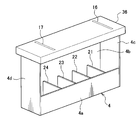
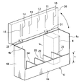
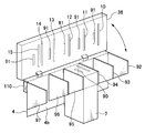
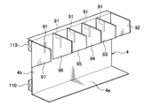
- FIG. 2 is a perspective view of the cassette loading frame 4 when the conveyance path frame 36 is opened.
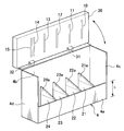
- FIG. 3 is a cassette loading when the conveyance path frame 36 is closed.
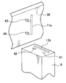
- 4 is a perspective view of the main part of the bill storage cassette 6 when the transport path frame 36 is opened,
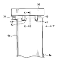
- FIG. 5 is a rear view of the main part when the transport path frame 36 is closed, and
- the cassette loading frame 4 has a height h of the side plate 4a on one side, which is the cassette operating side, less than half of the height of the cassettes 5 to 9, preferably about one third.
- the height of the side plate 4b on the other side opposite to the cassette operating side is set to the same height as the cassettes 5 to 9, and each cassette is stored between the front plate 4c and the rear plate 4d.
- a plurality of lower partition plates 21 to 24 for partitioning positions are provided at the lower part of the cassette loading frame 4, and the lower partition plates 21 to 24 have a height similar to the height of the side plate 4a.
- the cassettes 5 to 9 are arranged at intervals in the front-rear direction.
- the transport path frame 36 is attached to the upper end portion of the side plate 4b of the cassette loading frame 4 so as to rotate around the fulcrums 31 and 32 as shown in FIG.
- Guide holes 10 to 15 longer than the banknote width in the direction perpendicular to the banknote transport direction are provided in parallel on the lower surface side of the transport path frame 36, and each banknote receiving part of the transport path 3 shown in FIG.
- a delivery section (delivery guide) 37a is provided so as to be exposed on the cassette side, and a banknote delivery section 37b corresponding to the banknote delivery section 37a is exposed on the upper surface of each cassette 5-9 on the transport path frame 36 side. Is provided.
- guide holes 16 and 17 corresponding to the banknote delivery portions of the transport paths 34b and 34c are provided on the upper surface side of the transport path frame 36, and the same bills as the banknote delivery section 37a are also provided in the guide holes 16 and 17.
- a delivery section is provided.
- positioning pins (positioning portions) 43 and 44 are provided on the lower surface of the conveyance path frame 36 so as to be positioned in the vicinity of the guide hole 11, that is, in the vicinity of the bill delivery portion 37a.
- Positioning holes (positioning portions) 41 and 42 corresponding to the positioning pins 43 and 44 are provided on the upper surface side of the banknote storage cassette 6. That is, the positioning pins 43 and 44 and the positioning holes (positioning portions) 41 and 42 are provided on the mutually opposing surfaces of the transport path frame 36 and the bill storage cassette 6.
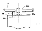
- the tips of the positioning pins 43 and 44 are provided in a conical shape, and the positioning hole 41 corresponding to the positioning pin 43 farther from the rotation fulcrum of the transport path frame 36 has a diameter slightly larger than the diameter of the positioning pin 43.
- the positioning hole 41 corresponding to the positioning pin 44 closer to the rotation fulcrum of the conveyance path frame 36 rotates the conveyance path frame 36 around the fulcrums 31 and 32. It is formed in a shape in which the left and right sides are widened in a tapered shape so as to allow the movement locus of the positioning pin 44 when opened and closed.
- positioning pins 43 and 44 are provided at predetermined intervals so as to be positioned similarly in the vicinity of the guide holes 10 and 12 to 15 of the conveyance path frame 36, that is, in the vicinity of the bill delivery portion 37a.
- positioning holes 41, 42 corresponding to the positioning pins 43, 44 are provided in the banknote storage cassettes 5, 7, 8 and the medium storage cassette 9.
- FIG. 7 is a perspective view showing the operation of the first embodiment.
- the conveyance path frame 36 is rotated around the fulcrums 31 and 32 as shown in the figure.
- the bill storage cassette 6 is lifted and lowered between the lower partition plates 21 and 22 of the cassette loading frame 4.
- the height h of the side plate 4a on the cassette operating side of the cassette loading frame 4 is less than half of the height of each cassette 5-9, for example, about one third of the cassette 5-9.
- the operation of lifting the storage cassette 6 and lowering it between the lower partition plates 21 and 22 of the cassette loading frame 4 can be easily performed.
- the height h of the side plate 4a is low, so that the taking out operation can be easily performed.
- the other cassettes 5 and 7 to 9 can be similarly loaded and unloaded from the cassette loading frame 4.
- the tip of the positioning pins 43, 44 is conical and the positioning holes 41, Since the entrance of 42 is expanded in a taper shape, the amount of deviation in the cassette loading frame 4 is absorbed, and the positioning pins 43 and 44 and the positioning holes 41 and 42 are connected to the bill delivery section 37a of the transport path 3 and each Since it is provided in the vicinity of the bill delivery portion 37b of the cassettes 5 to 9, the bill delivery portions 37a and 37b can be accurately positioned by fitting the positioning pins 43 and 44 into the positioning holes 41 and 42, respectively. it can.
- the lower unit 2 is pushed into the apparatus, so that the transport path frame 36, the cassette loading frame 4, the bill storage cassettes 5 to 8 and the medium storage cassette 9 are mounted on the apparatus.
- the banknote delivery part provided in the holes 16 and 17 and the banknote delivery part of the conveyance paths 34b and 34c are connected.
- banknote depositing and dispensing processes are performed in the same manner as before, but the banknote delivery part 37a of the transport path 3 and the banknote delivery part 37b of each of the cassettes 5 to 9 are positioned with high accuracy. It is possible to prevent the occurrence of jam at the portion.
- the height of the side plate on the cassette operation side of the cassette loading frame is lowered, and the positioning unit for positioning the banknote delivery unit of the transport path and the banknote delivery unit of each cassette Is provided on the opposite surface of each cassette and the conveyance path frame, so that the operability of loading and unloading the cassette with respect to the cassette loading frame is good, and the banknote delivery part of the conveyance path and the banknote delivery part of the cassette are positioned accurately.
- the medium processing apparatus can be obtained, and the structure is simple, so that the effect that it can be realized at low cost is obtained.
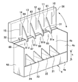
- FIG. 8 is a view showing the second embodiment, and is a perspective view of the cassette loading frame 4 when the conveyance path frame 36 is opened.
- the lower partition plates 21 to 24 provided in the cassette loading frame 4 have different left and right heights. Specifically, the lower partition plate on the side plate 4b side of the cassette loading frame 4 is used. The height of 21 to 24 is made higher than the height of the side plate 4a on the cassette operating side of the cassette loading frame 4 to form right-angled triangular guide portions 21a to 24a.
- a bill delivery portion 37b corresponding to the bill delivery portion 37a is provided on the upper surface side of each of the cassettes 5-9.
- guide holes 16 and 17 corresponding to the banknote delivery portions of the transport paths 34b and 34c are provided on the upper surface side of the transport path frame 36, and the same bills as the banknote delivery section 37a are also provided in the guide holes 16 and 17.
- a delivery section is provided.
- positioning pins 43 and 44 are provided on the lower surface of the conveyance path frame 36 at a predetermined interval so as to be positioned in the vicinity of the guide hole 11, that is, in the vicinity of the bill delivery portion 37a, for example.
- the positioning holes 41 and 42 corresponding to the positioning pins 43 and 44 are provided in the banknote storage cassette 6.
- the cassettes 5 to 9 when the cassettes 5 to 9 are loaded into the cassette loading frame 4, the cassettes 5 to 9 are individually lifted up to the height of the side plate 4a of the cassette loading frame 4, and the side plates are left as they are.
- the cassettes 5 to 9 When pushed into the side 4b, the cassettes 5 to 9 are guided while their positions are regulated by the guide portions 21a to 24a of the lower partition plates 21 to 24, respectively.
- the positions of the lower ends of the cassettes 5 to 9 are regulated by the guide portions 21a to 24a, so that the cassette to be taken out is prevented from hitting the adjacent cassette and being damaged. be able to.
- the positioning pins 43 and 44 of the conveyance path frame 36 are fitted and positioned in the positioning holes 41 and 42 of the cassettes 5 to 9. It is.
- the same effects as those of the first embodiment can be obtained, and when the cassette is loaded into the cassette loading frame by the guide portion formed on the lower partition plate, and the cassette is loaded into the cassette loading frame. Since the position restriction and the guide when taking out from 4 are performed, the operability at the time of loading and taking out each cassette can be further improved.
- FIG. 9 is a perspective view of the cassette loading frame 4 when the transport path frame 36 is opened
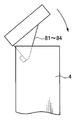
- FIG. 10 is a perspective view of the transport path frame 36 and the cassette showing the operation of the third embodiment.
- 4 is a rear view of the loading frame 4.
- upper partition plates 81 to 84 are provided on the lower surface of the conveyance path frame 36 so as to correspond to the lower partition plates 21 to 24 provided in the cassette loading frame 4.
- the plates 81 to 84 are formed in a substantially right triangle shape or the like, and have projections 81a to 84a at their tips (lower ends), and relief holes 85 to 88 through which the projections 81a to 84a escape are side plates of the cassette loading frame 4. 4b.
- each banknote delivery section in the transport path 3 shown in FIG. A delivery guide 37a is provided, and a bill delivery portion 37b corresponding to the bill delivery portion 37a is provided on the upper surface side of each cassette 5-9. Further, guide holes 16 and 17 corresponding to the banknote delivery portions of the transport paths 34b and 34c are provided on the upper surface side of the transport path frame 36, and the same bills as the banknote delivery section 37a are also provided in the guide holes 16 and 17. A delivery section is provided.
- positioning pins 43 and 44 are provided on the lower surface of the conveyance path frame 36 at a predetermined interval so as to be positioned in the vicinity of the guide hole 11, that is, in the vicinity of the bill delivery portion 37a, for example.
- the positioning holes 41 and 42 corresponding to the positioning pins 43 and 44 are provided in the banknote storage cassette 6.
- the conveyance path frame 36 is rotated around the fulcrums 31 and 32 and closed. Then, the positioning pins of the transport path frame 36 are fitted and positioned in the positioning holes 41 and 42 of the cassettes 5 to 9, and at this time, as shown in FIGS. 10 (a) and 10 (b), the transport path frame As the upper plate 36 is closed, the upper partition plates 81 to 84 function to regulate the upper portions of the cassettes 5 to 9, so that the positioning pins can be smoothly fitted into the positioning holes 41 and 42.
- the same effect as in the second embodiment can be obtained, and an upper partition plate is provided on the transport path frame, and the upper partition plate covers the upper portion of the cassette when the transport path frame is closed. Since the restriction is made, the positioning pin can be smoothly fitted into the positioning hole, and as a result, accurate positioning of the banknote delivery portion of the transport path and the banknote delivery portion of the cassette can be stably performed. The effect that it becomes possible is obtained.
- FIG. 11 is a view showing the fourth embodiment, and is a perspective view of the cassette loading frame 4 when the transport path frame 36 is opened
- FIG. 12 is a perspective view of the main part of the fourth embodiment.
- the cassette loading frame 4 is divided into side plates 4b on the side opposite to the cassette operating side, and partition plates 92 to 97 are provided at intervals in the longitudinal direction of the cassettes 5 to 9.
- the transport path frame 36 is attached to the upper end portion of the side plate 4b so as to open and close by rotating around the fulcrums 31 and 32.
- the fourth embodiment by inserting the upper portions of the cassettes 5 to 9 between the partition plates 92 and 93, between the partition plates 93 and 94,... Between the partition plates 96 and 97, respectively.
- the cassettes 5 to 9 are loaded.
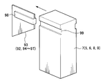
- projections 98 having a predetermined length are provided on both sides of the partition plates 92 to 97, and the front and back surfaces of the cassettes 5 to 9 are provided.
- a groove portion 99 is provided that is slidably fitted to the convex portion 98.
- electrical contacts 90 and 91 in the form of jack-in connectors that are fitted to each other are provided on the upper surface of each of the cassettes 5 to 9 and the lower surface of the transport path frame 36, and the cassette on the side plate of the cassette loading frame 4 is mounted.
- the lower unit 2 including the cassette loading frame 4, the cassettes 5 to 9 and the transport path frame 36 is provided on the surface opposite to the surface with a slide rail 110 for pulling out or pushing into the front side of the apparatus.
- the slide rail 110 is engaged with a slide rail (not shown) on the apparatus side.
- each bill receiving portion of the transport path 3 shown in FIG. A delivery section (delivery guide) 37a is provided, and a banknote delivery section 37b corresponding to the banknote delivery section 37a is provided on the upper surface side of each cassette 5-9. Further, guide holes 16 and 17 corresponding to the banknote delivery portions of the transport paths 34b and 34c are provided on the upper surface side of the transport path frame 36, and the same bills as the banknote delivery section 37a are also provided in the guide holes 16 and 17.
- a delivery section is provided.
- positioning pins 43 and 44 are provided on the lower surface of the conveyance path frame 36 at a predetermined interval so as to be positioned in the vicinity of the guide hole 11, that is, in the vicinity of the bill delivery portion 37a, for example.
- the positioning holes 41 and 42 corresponding to the positioning pins 43 and 44 are provided in the banknote storage cassette 6.
- the cassettes 5 to 9 are slightly lifted to fit the groove portions 99 of the cassettes 5 to 9 into the convex portions 98 of the partition plates 92 to 97.
- the conveyance path frame 36 is rotated around the fulcrums 31 and 32 and closed.
- the positioning pins of the frame 36 are fitted into the positioning holes 41 and 42 of the cassettes 5 to 9 for positioning.
- the cassette loading frame 4 and the cassettes 5 to 5 are connected.
- the electrical contact 91 on the transport path frame 36 side is connected to the power source of the apparatus, so that it is provided on each cassette 5-9 side. It becomes possible to supply the driving power for the bill feeding section and storage section.
- the cassette loading frame 4 is composed of only the side plate 4b opposite to the cassette operating side, but the structure shown in FIG. 13 may be used.
- FIG. 13 is a perspective view showing another example of the cassette loading frame 4, and the cassette loading frame 4 is constituted by the side plate 4b and the bottom plate 4e.
- the cassettes 5 to 9 are loaded by providing the bottom plate 4e in this way, the cassettes 5 to 9 are placed on the bottom plate 4e, and the groove portions 99 of the cassettes 5 to 9 are formed on the convex portions 98 of the partition plates 92 to 97. After the fitting, the cassettes 5 to 9 are pushed into the side plate 4b of the cassette loading frame 4 so that the cassettes 5 to 9 can be easily loaded between the partition plates 92 to 97.
- electrical contacts 90 and 91 in the form of jack-in connectors that are fitted to each other are provided on the upper surfaces of the cassettes 5 to 9 and the lower surface of the transport path frame 36.
- the electrical contacts 91 are provided on the side plate 4b of the cassette loading frame 4 so as to be positioned between the partition plates 92 to 97, and the electrical contacts 90 are provided on the side surfaces of the cassettes 5 to 9 facing the side plate 4b.
- the lower unit 2 including the cassette loading frame 4, the cassettes 5 to 9 and the transport path frame 36 is arranged on the front side of the apparatus on the surface opposite to the cassette mounting surface of the side plate of the cassette loading frame 4.
- the cassette loading frame has a configuration in which partition plates are provided on at least one side plate at intervals in the front-rear direction of each cassette, and each partition plate has a predetermined length.
- a groove portion is provided on the front and rear surfaces of each cassette so as to be slidably fitted with the convex portion. The convex portion and the groove portion are fitted together to push each cassette to the side plate side of the cassette loading frame. Since each cassette can be loaded and unloaded by pulling it out, it is only necessary to lift each cassette a little when loading or unloading each cassette, resulting in improved operability. It is done.
- positioning pins 43 and 44 for positioning the banknote delivery section of the transport path and the banknote delivery section of each cassette are provided on the transport path frame 36, and positioning holes 41 corresponding to the positioning pins 43 and 44 are provided. , 42 are provided in the cassettes 5-9, but the positioning pins 43, 44 may be provided in the cassettes 5-9, and the positioning holes 41, 42 may be provided in the transport path frame 36.
- positioning pins and positioning holes it is not necessary to provide a plurality of positioning pins and positioning holes, and it is possible to use one rectangular positioning pin and one rectangular positioning hole as a positioning portion. Further, instead of the positioning pin and the positioning hole, a small piece plate It is also possible to provide a slit as a positioning part.
- electrical contacts 90 and 91 are provided in the same manner as in the fourth embodiment.
- each embodiment described above has been described by taking a banknote depositing / dispensing machine as an example.
- the present invention can be applied to various apparatuses as long as the medium processing apparatus includes a plurality of medium storage cassettes and conveyance paths.
Landscapes
- Engineering & Computer Science (AREA)
- Mechanical Engineering (AREA)
- Physics & Mathematics (AREA)
- General Physics & Mathematics (AREA)
- Pile Receivers (AREA)
- Sheets, Magazines, And Separation Thereof (AREA)
- Battery Mounting, Suspending (AREA)
- Warehouses Or Storage Devices (AREA)
Priority Applications (2)
| Application Number | Priority Date | Filing Date | Title |
|---|---|---|---|
| CN201080054226.XA CN102656611B (zh) | 2009-12-03 | 2010-11-19 | 介质处理装置 |
| US13/513,570 US8684153B2 (en) | 2009-12-03 | 2010-11-19 | Media processing device |
Applications Claiming Priority (2)
| Application Number | Priority Date | Filing Date | Title |
|---|---|---|---|
| JP2009275854A JP5434538B2 (ja) | 2009-12-03 | 2009-12-03 | 媒体処理装置 |
| JP2009-275854 | 2009-12-03 |
Publications (1)
| Publication Number | Publication Date |
|---|---|
| WO2011068048A1 true WO2011068048A1 (ja) | 2011-06-09 |
Family
ID=44114897
Family Applications (1)
| Application Number | Title | Priority Date | Filing Date |
|---|---|---|---|
| PCT/JP2010/070737 Ceased WO2011068048A1 (ja) | 2009-12-03 | 2010-11-19 | 媒体処理装置 |
Country Status (4)
| Country | Link |
|---|---|
| US (1) | US8684153B2 (enExample) |
| JP (1) | JP5434538B2 (enExample) |
| CN (5) | CN102656611B (enExample) |
| WO (1) | WO2011068048A1 (enExample) |
Cited By (1)
| Publication number | Priority date | Publication date | Assignee | Title |
|---|---|---|---|---|
| CN103442617A (zh) * | 2012-03-29 | 2013-12-11 | 冲电气工业株式会社 | 拉出装置及介质交易装置 |
Families Citing this family (22)
| Publication number | Priority date | Publication date | Assignee | Title |
|---|---|---|---|---|
| JP5699043B2 (ja) * | 2011-06-20 | 2015-04-08 | ローレル精機株式会社 | 紙幣処理装置 |
| JP5527347B2 (ja) | 2012-03-26 | 2014-06-18 | 沖電気工業株式会社 | 紙葉類収納庫及び紙葉類取扱装置 |
| JP6031792B2 (ja) * | 2012-03-29 | 2016-11-24 | 沖電気工業株式会社 | 現金自動預払機 |
| JP5974624B2 (ja) * | 2012-05-17 | 2016-08-23 | 沖電気工業株式会社 | 紙葉類搬送装置及び紙葉類取扱装置 |
| JP5949487B2 (ja) * | 2012-11-16 | 2016-07-06 | 沖電気工業株式会社 | 紙葉類搬送装置及び紙葉類取扱装置 |
| JP6327785B2 (ja) * | 2012-12-05 | 2018-05-23 | 沖電気工業株式会社 | 媒体処理装置 |
| CN103903345A (zh) * | 2012-12-29 | 2014-07-02 | 鸿富锦精密工业(武汉)有限公司 | 自动售货机机柜 |
| JP6349069B2 (ja) * | 2013-10-18 | 2018-06-27 | 日立アプライアンス株式会社 | ドラム式洗濯機 |
| JP5790797B2 (ja) * | 2014-01-17 | 2015-10-07 | 沖電気工業株式会社 | 紙葉類取扱装置及び紙葉類収納庫 |
| JP6369196B2 (ja) | 2014-07-25 | 2018-08-08 | 沖電気工業株式会社 | 媒体処理装置及び媒体取引装置 |
| CN104103125B (zh) * | 2014-08-08 | 2017-03-22 | 广州广电运通金融电子股份有限公司 | 钞箱及其纸币尺寸调节装置 |
| CN104240383B (zh) | 2014-09-24 | 2017-01-25 | 广州广电运通金融电子股份有限公司 | 一种纸币回收箱以及纸币处理装置 |
| WO2016079754A2 (en) * | 2014-11-19 | 2016-05-26 | Badr M Al Refae | Media dispenser cassette mechanism (mdcm) |
| WO2016194442A1 (ja) * | 2015-06-03 | 2016-12-08 | 日立オムロンターミナルソリューションズ株式会社 | 紙葉類集積庫、現金自動取引装置 |
| CN105023343B (zh) * | 2015-07-15 | 2017-11-07 | 深圳怡化电脑股份有限公司 | 下通道模组与钞箱对接结构 |
| WO2017110833A1 (ja) * | 2015-12-22 | 2017-06-29 | 沖電気工業株式会社 | 媒体処理装置及び媒体取引装置 |
| JP6696299B2 (ja) | 2016-05-19 | 2020-05-20 | 沖電気工業株式会社 | 保護具、媒体収納装置及び媒体処理装置 |
| TWI607416B (zh) * | 2016-12-08 | 2017-12-01 | Masterwork Automodules Tech Corp Ltd | 紙頁處理設備 |
| CN107718907A (zh) * | 2017-09-30 | 2018-02-23 | 贵州云侠科技有限公司 | 打印机送纸部和打印机 |
| CN109516246B (zh) * | 2018-09-28 | 2020-08-18 | 泰州市博泰电子有限公司 | 一种配页机用输送装置 |
| JP7582203B2 (ja) | 2019-11-26 | 2024-11-13 | 沖電気工業株式会社 | 媒体処理装置、及び、当該媒体処理装置に用いるカセット装填ユニット |
| JP2024025420A (ja) * | 2022-08-12 | 2024-02-26 | グローリー株式会社 | 貨幣処理装置、貨幣処理装置の製造方法、およびプログラム |
Citations (4)
| Publication number | Priority date | Publication date | Assignee | Title |
|---|---|---|---|---|
| JPH0458390A (ja) * | 1990-06-28 | 1992-02-25 | Oki Electric Ind Co Ltd | 紙幣入出金装置 |
| JPH09235061A (ja) * | 1996-03-01 | 1997-09-09 | Omron Corp | 紙葉類収納装置および取引処理装置 |
| JP2001006018A (ja) * | 1999-06-25 | 2001-01-12 | Hitachi Ltd | 紙幣取扱装置 |
| JP2009258929A (ja) * | 2008-04-15 | 2009-11-05 | Oki Electric Ind Co Ltd | カセット装着装置 |
Family Cites Families (7)
| Publication number | Priority date | Publication date | Assignee | Title |
|---|---|---|---|---|
| JPS58135043A (ja) * | 1982-02-04 | 1983-08-11 | Laurel Bank Mach Co Ltd | 自動入出金機における紙幣分離送出機構 |
| JPS6134241U (ja) * | 1984-07-31 | 1986-03-01 | 教雄 小島 | 患者別薬剤仕分収納ケ−ス |
| JPS63177289A (ja) * | 1987-01-19 | 1988-07-21 | 株式会社東芝 | 紙葉類処理装置 |
| ES2132226T3 (es) * | 1992-04-16 | 1999-08-16 | Mars Inc | Dispositivo para la lectura de billetes de banco. |
| JP4684827B2 (ja) * | 2005-09-27 | 2011-05-18 | ローレル機械株式会社 | 硬貨入金機 |
| US20080007146A1 (en) * | 2006-05-18 | 2008-01-10 | De La Rue International Limited | Cash dispenser |
| JP5292761B2 (ja) | 2007-10-16 | 2013-09-18 | 沖電気工業株式会社 | 紙幣分離集積機構 |
-
2009
- 2009-12-03 JP JP2009275854A patent/JP5434538B2/ja active Active
-
2010
- 2010-11-19 WO PCT/JP2010/070737 patent/WO2011068048A1/ja not_active Ceased
- 2010-11-19 CN CN201080054226.XA patent/CN102656611B/zh active Active
- 2010-11-19 CN CN201410051527.7A patent/CN103818790B/zh not_active Expired - Fee Related
- 2010-11-19 CN CN201610892490.XA patent/CN107093260A/zh active Pending
- 2010-11-19 CN CN201410052077.3A patent/CN103824376B/zh active Active
- 2010-11-19 CN CN201410052073.5A patent/CN103818791B/zh active Active
- 2010-11-19 US US13/513,570 patent/US8684153B2/en active Active
Patent Citations (4)
| Publication number | Priority date | Publication date | Assignee | Title |
|---|---|---|---|---|
| JPH0458390A (ja) * | 1990-06-28 | 1992-02-25 | Oki Electric Ind Co Ltd | 紙幣入出金装置 |
| JPH09235061A (ja) * | 1996-03-01 | 1997-09-09 | Omron Corp | 紙葉類収納装置および取引処理装置 |
| JP2001006018A (ja) * | 1999-06-25 | 2001-01-12 | Hitachi Ltd | 紙幣取扱装置 |
| JP2009258929A (ja) * | 2008-04-15 | 2009-11-05 | Oki Electric Ind Co Ltd | カセット装着装置 |
Cited By (2)
| Publication number | Priority date | Publication date | Assignee | Title |
|---|---|---|---|---|
| CN103442617A (zh) * | 2012-03-29 | 2013-12-11 | 冲电气工业株式会社 | 拉出装置及介质交易装置 |
| CN103442617B (zh) * | 2012-03-29 | 2015-11-25 | 冲电气工业株式会社 | 拉出装置及介质交易装置 |
Also Published As
| Publication number | Publication date |
|---|---|
| CN102656611A (zh) | 2012-09-05 |
| CN103818790B (zh) | 2016-07-20 |
| JP2011118699A (ja) | 2011-06-16 |
| CN103824376B (zh) | 2016-01-27 |
| CN103818791B (zh) | 2017-07-18 |
| CN103818791A (zh) | 2014-05-28 |
| CN103818790A (zh) | 2014-05-28 |
| CN107093260A (zh) | 2017-08-25 |
| US20120255829A1 (en) | 2012-10-11 |
| JP5434538B2 (ja) | 2014-03-05 |
| CN102656611B (zh) | 2016-11-16 |
| US8684153B2 (en) | 2014-04-01 |
| CN103824376A (zh) | 2014-05-28 |
Similar Documents
| Publication | Publication Date | Title |
|---|---|---|
| JP5434538B2 (ja) | 媒体処理装置 | |
| JP6246506B2 (ja) | 貨幣カセット補充装置 | |
| JP3914807B2 (ja) | 紙幣入出金装置 | |
| CN107004320B (zh) | 介质处理装置和介质交易装置 | |
| JP5672364B2 (ja) | 媒体処理装置 | |
| TW201942876A (zh) | 給紙托盤,給紙裝置,以及回流式紙片處理裝置 | |
| JP6102487B2 (ja) | 媒体収納装置及び媒体取引装置 | |
| JP5672402B2 (ja) | 媒体処理装置 | |
| WO2015174352A1 (ja) | 媒体処理装置及び媒体収納カセット | |
| JP7196360B2 (ja) | 紙葉類取扱装置 | |
| WO2014034246A1 (ja) | 紙葉類取扱装置及び紙葉類収納庫 | |
| CN108292458B (zh) | 介质处理装置和介质交易装置 | |
| JP2001118115A (ja) | 受渡構造 | |
| JP7424215B2 (ja) | 媒体処理装置及び現金取扱装置 | |
| JP6237911B2 (ja) | 媒体搬送識別装置及び媒体取引装置 | |
| JP5795877B2 (ja) | 紙幣処理装置 | |
| JP6927011B2 (ja) | 紙葉類収容装置、紙葉類処理装置 | |
| JP6702040B2 (ja) | 媒体処理装置 | |
| WO2021166258A1 (ja) | 紙葉類取扱装置 | |
| JP2016099811A (ja) | 帯電防止機構及び媒体取引装置 | |
| WO2014080700A1 (ja) | 媒体集積装置及び媒体取引装置 | |
| JP2021149425A (ja) | 硬貨入出金装置及びプログラム | |
| JP2017187997A (ja) | 装填機構及び媒体処理装置 | |
| JP2017151807A (ja) | 装填機構及び媒体処理装置 | |
| JP2013058023A (ja) | 媒体集積装置及び媒体取引装置 |
Legal Events
| Date | Code | Title | Description |
|---|---|---|---|
| WWE | Wipo information: entry into national phase |
Ref document number: 201080054226.X Country of ref document: CN |
|
| 121 | Ep: the epo has been informed by wipo that ep was designated in this application |
Ref document number: 10834500 Country of ref document: EP Kind code of ref document: A1 |
|
| NENP | Non-entry into the national phase |
Ref country code: DE |
|
| WWE | Wipo information: entry into national phase |
Ref document number: 13513570 Country of ref document: US |
|
| 122 | Ep: pct application non-entry in european phase |
Ref document number: 10834500 Country of ref document: EP Kind code of ref document: A1 |