WO2011065452A1 - 印刷データ生成装置、印刷データ生成方法及び印刷データ生成プログラム - Google Patents
印刷データ生成装置、印刷データ生成方法及び印刷データ生成プログラム Download PDFInfo
- Publication number
- WO2011065452A1 WO2011065452A1 PCT/JP2010/071073 JP2010071073W WO2011065452A1 WO 2011065452 A1 WO2011065452 A1 WO 2011065452A1 JP 2010071073 W JP2010071073 W JP 2010071073W WO 2011065452 A1 WO2011065452 A1 WO 2011065452A1
- Authority
- WO
- WIPO (PCT)
- Prior art keywords
- dot size
- print data
- dot
- dots
- data generation
- Prior art date
Links
Images


Classifications
-
- B—PERFORMING OPERATIONS; TRANSPORTING
- B41—PRINTING; LINING MACHINES; TYPEWRITERS; STAMPS
- B41J—TYPEWRITERS; SELECTIVE PRINTING MECHANISMS, i.e. MECHANISMS PRINTING OTHERWISE THAN FROM A FORME; CORRECTION OF TYPOGRAPHICAL ERRORS
- B41J2/00—Typewriters or selective printing mechanisms characterised by the printing or marking process for which they are designed
- B41J2/005—Typewriters or selective printing mechanisms characterised by the printing or marking process for which they are designed characterised by bringing liquid or particles selectively into contact with a printing material
- B41J2/01—Ink jet
- B41J2/21—Ink jet for multi-colour printing
- B41J2/2121—Ink jet for multi-colour printing characterised by dot size, e.g. combinations of printed dots of different diameter
- B41J2/2128—Ink jet for multi-colour printing characterised by dot size, e.g. combinations of printed dots of different diameter by means of energy modulation
-
- B—PERFORMING OPERATIONS; TRANSPORTING
- B41—PRINTING; LINING MACHINES; TYPEWRITERS; STAMPS
- B41J—TYPEWRITERS; SELECTIVE PRINTING MECHANISMS, i.e. MECHANISMS PRINTING OTHERWISE THAN FROM A FORME; CORRECTION OF TYPOGRAPHICAL ERRORS
- B41J2/00—Typewriters or selective printing mechanisms characterised by the printing or marking process for which they are designed
- B41J2/005—Typewriters or selective printing mechanisms characterised by the printing or marking process for which they are designed characterised by bringing liquid or particles selectively into contact with a printing material
- B41J2/01—Ink jet
-
- B—PERFORMING OPERATIONS; TRANSPORTING
- B41—PRINTING; LINING MACHINES; TYPEWRITERS; STAMPS
- B41J—TYPEWRITERS; SELECTIVE PRINTING MECHANISMS, i.e. MECHANISMS PRINTING OTHERWISE THAN FROM A FORME; CORRECTION OF TYPOGRAPHICAL ERRORS
- B41J19/00—Character- or line-spacing mechanisms
- B41J19/14—Character- or line-spacing mechanisms with means for effecting line or character spacing in either direction
- B41J19/142—Character- or line-spacing mechanisms with means for effecting line or character spacing in either direction with a reciprocating print head printing in both directions across the paper width
- B41J19/145—Dot misalignment correction
-
- B—PERFORMING OPERATIONS; TRANSPORTING
- B41—PRINTING; LINING MACHINES; TYPEWRITERS; STAMPS
- B41J—TYPEWRITERS; SELECTIVE PRINTING MECHANISMS, i.e. MECHANISMS PRINTING OTHERWISE THAN FROM A FORME; CORRECTION OF TYPOGRAPHICAL ERRORS
- B41J2/00—Typewriters or selective printing mechanisms characterised by the printing or marking process for which they are designed
- B41J2/005—Typewriters or selective printing mechanisms characterised by the printing or marking process for which they are designed characterised by bringing liquid or particles selectively into contact with a printing material
- B41J2/01—Ink jet
- B41J2/205—Ink jet for printing a discrete number of tones
- B41J2/2056—Ink jet for printing a discrete number of tones by ink density change
-
- B—PERFORMING OPERATIONS; TRANSPORTING
- B41—PRINTING; LINING MACHINES; TYPEWRITERS; STAMPS
- B41J—TYPEWRITERS; SELECTIVE PRINTING MECHANISMS, i.e. MECHANISMS PRINTING OTHERWISE THAN FROM A FORME; CORRECTION OF TYPOGRAPHICAL ERRORS
- B41J2/00—Typewriters or selective printing mechanisms characterised by the printing or marking process for which they are designed
- B41J2/005—Typewriters or selective printing mechanisms characterised by the printing or marking process for which they are designed characterised by bringing liquid or particles selectively into contact with a printing material
- B41J2/01—Ink jet
- B41J2/21—Ink jet for multi-colour printing
- B41J2/2132—Print quality control characterised by dot disposition, e.g. for reducing white stripes or banding
- B41J2/2139—Compensation for malfunctioning nozzles creating dot place or dot size errors
-
- B—PERFORMING OPERATIONS; TRANSPORTING
- B41—PRINTING; LINING MACHINES; TYPEWRITERS; STAMPS
- B41J—TYPEWRITERS; SELECTIVE PRINTING MECHANISMS, i.e. MECHANISMS PRINTING OTHERWISE THAN FROM A FORME; CORRECTION OF TYPOGRAPHICAL ERRORS
- B41J2/00—Typewriters or selective printing mechanisms characterised by the printing or marking process for which they are designed
- B41J2/005—Typewriters or selective printing mechanisms characterised by the printing or marking process for which they are designed characterised by bringing liquid or particles selectively into contact with a printing material
- B41J2/01—Ink jet
- B41J2/21—Ink jet for multi-colour printing
- B41J2/2132—Print quality control characterised by dot disposition, e.g. for reducing white stripes or banding
- B41J2/2146—Print quality control characterised by dot disposition, e.g. for reducing white stripes or banding for line print heads
-
- B—PERFORMING OPERATIONS; TRANSPORTING
- B41—PRINTING; LINING MACHINES; TYPEWRITERS; STAMPS
- B41J—TYPEWRITERS; SELECTIVE PRINTING MECHANISMS, i.e. MECHANISMS PRINTING OTHERWISE THAN FROM A FORME; CORRECTION OF TYPOGRAPHICAL ERRORS
- B41J29/00—Details of, or accessories for, typewriters or selective printing mechanisms not otherwise provided for
- B41J29/38—Drives, motors, controls or automatic cut-off devices for the entire printing mechanism
Definitions
- the present invention relates to a print data generation apparatus, a print data generation method, and a print data generation program for generating print data by ejecting ink droplets from each nozzle of an inkjet head to form dots on a recording medium at a predetermined resolution pitch.
- Patent Document 1 describes a technique that enables the dot size to be changed.
- the technique described in Patent Document 1 enables selection of small dots and large dots in order to increase the efficiency of image formation. For this reason, even if it uses the technique described in patent document 1, generation
- an object of the present invention is to provide a print data generation device, a print data generation method, and a print data generation program that can suppress the occurrence of streak unevenness in a print image printed by an inkjet printer.
- a print data generation apparatus is a print data generation apparatus that generates print data by ejecting ink droplets from each nozzle of an inkjet head to form dots on a recording medium at a predetermined resolution pitch.
- a dot size setting unit for setting the dot size larger than the resolution pitch is provided.
- the setting of the dot size can be changed, for example, by increasing the number of ink droplet ejections or increasing the ink droplet ejection amount.
- the resolution pitch indicates the distance between the centers of adjacent pixels.
- the dot size setting unit sets the dot size so that the overlapping width of the adjacent dots in the direction orthogonal to the straight line passing through the center of the adjacent dots is twice the resolution pitch.
- the dot size setting unit preferably sets the dot diameter to 2.3 to 3.5 times the resolution pitch. Also by doing this, it is possible to easily and appropriately suppress the occurrence of streak unevenness by eliminating the gap between the dots adjacent in the oblique direction.
- the dot size setting unit sets the dot size according to the degree (degree) of occurrence of streak unevenness.
- the dot size setting unit sets the dot size according to the degree (degree) of occurrence of streak unevenness.
- the dot size setting unit sets the dot size according to the amount of deviation of the landing position of the ink droplet.
- the dot size setting unit sets the dot size according to the amount of deviation of the landing position of the ink droplet.
- a contour detection unit that detects pixels corresponding to the contour is further provided, and the dot size setting unit sets the dot size of the pixel detected by the contour detection unit to be smaller than the dot size of the other pixels.
- the dot size setting unit sets the dot size of the pixel detected by the contour detection unit to be smaller than the dot size of the other pixels.
- the dot size setting unit preferably sets the dot size of the pixel detected by the contour detection unit to 1.0 to 2.5 times the resolution pitch. By doing in this way, it is possible to easily and appropriately suppress the occurrence of streak unevenness while suppressing a decrease in resolution.
- the ink density it is preferable to lower the ink density so that a desired ink density can be obtained at a predetermined overlapping area ratio. In this way, by reducing the ink density, it is possible to prevent the ink density from becoming too high even if dots overlap.
- a print data generation method is a print data generation method for generating print data by ejecting ink droplets from each nozzle of an inkjet head to form dots on a recording medium at a predetermined resolution pitch.
- a dot size setting step for setting the dot size larger than the resolution pitch is provided.
- the dot size of the dots formed on the recording medium is set larger than the resolution pitch to generate the print data. Therefore, the dots formed on the recording medium can be superimposed. it can. As a result, gaps between adjacent dots can be filled, and even when the ink droplet landing position is shifted due to variations in the ejection characteristics of the nozzles, the occurrence of streak irregularity can be suppressed.
- a print data generation program is a print data generation program for generating print data for ejecting ink droplets from each nozzle of an inkjet head to form dots on a recording medium at a predetermined resolution pitch. And a dot size setting step for setting a dot size larger than the resolution pitch.
- the dot size of the dots formed on the recording medium is set larger than the resolution pitch to generate the print data. Therefore, the dots formed on the recording medium can be superimposed. it can. As a result, gaps between adjacent dots can be filled, and even when the ink droplet landing position is shifted due to variations in the ejection characteristics of the nozzles, the occurrence of streak irregularity can be suppressed.
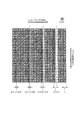
- FIG. 6 is a diagram illustrating streak unevenness that occurs when the landing positions of ink droplets are shifted. It is an enlarged view showing a printing pattern when the dot size is enlarged to 21/2 times the resolution pitch. It is the enlarged view which showed the printing pattern at the time of enlarging dot size to 2 times the resolution pitch. It is the enlarged view which showed the printing pattern at the time of enlarging dot size to 3 times the resolution pitch. It is a figure for calculating the conditions in which a stripe nonuniformity does not appear.
- FIG. 9 is an enlarged view showing a printing pattern when the dot diameter is enlarged to three times the resolution pitch in FIG. 8. It is the enlarged view which showed the printing pattern at the time of removing the pixel of an outline and expanding dot size. It is the enlarged view which showed the printing pattern at the time of removing a pixel other than an outline and expanding dot size.
- FIG. 5 is a diagram illustrating a dot ink density curve with respect to a dot overlap area rate. It is a figure which shows the functional block structure of RIP. It is a flowchart which shows the processing operation of RIP. It is a figure for demonstrating operation
- FIG. 1 is a diagram showing a configuration of an inkjet printer system including a RIP according to the present embodiment.
- the inkjet printer system 1 includes an inkjet printer 10 and a personal computer 20.
- the personal computer 20 incorporates an application 30 for creating image data to be printed by the inkjet printer 10 and a RIP 40 for converting the image data into print data for printing by the inkjet printer 10.
- the inkjet printer 10 is provided with a carriage 11 that can reciprocate in the scanning direction, and an inkjet head 12 that ejects ink droplets is mounted on the carriage 11.
- the inkjet head 12 is formed with a plurality of nozzles 13 for ejecting ink droplets, and the plurality of nozzles 13 are arranged in a direction perpendicular to the scanning direction in which the carriage 11 moves.
- the scanning direction in which the carriage 11 moves is the head movement direction S
- the direction in which the nozzles 13 are arranged and perpendicular to the head movement direction S is the head nozzle row direction L.
- the inkjet printer 10 ejects ink droplets from the nozzles 13 of the inkjet head 12 while reciprocating the carriage 11 in the scanning direction, thereby forming a plurality of dots on the recording medium.
- the RIP 40 generates dot format print data for printing with the inkjet printer 10 based on image data such as a dot map format or JPEG format created by the application 30.
- This print data forms dots on a recording medium at a predetermined resolution pitch, and is configured for each pixel by whether or not ink droplets are ejected, the number of ink droplet ejections, the amount of ink droplets, and the like.
- the RIP 40 sets the dot size of each pixel to be larger than the resolution pitch in order to reduce streak unevenness occurring in the printed image, and the ink is formed so that dots are formed on the recording medium with the set dot size.
- the number of droplet discharges and the appropriate discharge amount of ink liquid are calculated, and print data is created based on the calculation results. Note that increasing the number of ink droplet ejection increases the size of dots formed on the recording medium, and increasing the amount of ink droplet ejection increases the size of dots formed on the recording medium.
- FIG. 6 is a diagram for calculating a condition in which streak unevenness does not appear.
- the dot centered at point A is dot A
- the dot centered at point B is dot B
- the dot centered at point C is dot C.
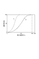
- FIG. 7 is a diagram showing the relationship between the amount of deviation of the landing position where the stripe unevenness does not occur and the dot radius.
- the dot radius R when the dot radius R is changed between 1.18P and 1.414P according to the amount of deviation of the landing position, the generation of gaps due to the landing deviation of the dots can be prevented, and streak unevenness can be prevented. It can be lost.
- the dot diameter D is set to 2.828P (radius R is 1.414) or more, the generation of gaps can be prevented against landing deviation of all dots. Since the dot size changes depending on various other factors, it is preferable to set the dot diameter D between 2.3P and 3.5P according to the amount of deviation of the landing position.
- the pixel corresponding to the contour of the image is detected, and the dot size of the pixel corresponding to the contour is set to be smaller than the dot size of the other pixels, thereby suppressing a decrease in resolution.
- FIG. 10 is an enlarged view showing a print pattern when the dot size is enlarged by removing the outline pixels.
- the diameter D of the dots is expanded to 3 times the resolution pitch P.
- the pixel corresponding to the contour is one pixel, but may be two or more pixels as long as streak unevenness does not occur.
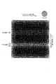
- FIG. 11 is an enlarged view showing a printing pattern when the dot size is enlarged by removing pixels other than the outline.
- the dot diameter D is enlarged to 21 ⁇ 2 times the resolution pitch P.
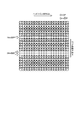
- FIG. 12 is an enlarged view showing a print pattern when the pixel data of the contour and the data of the pixels other than the contour are combined. As shown in FIG. 12, in this printed pattern, the gaps between the dots are filled and no streak is generated, and the lines with one line removed and the lines with two lines removed are clearly reproduced without being crushed. You can see that.
- the print density can also be lowered simply by reducing the discharge dot density per unit area.
- the discharge density that can be used is limited only to the low density side, and it is conceivable that the gradation is impaired.
- the ink density of each dot is lowered so that the ink density does not become too high when the dots overlap.
- FIG. 13 is a diagram showing a dot ink density curve with respect to a dot overlap area ratio.
- ⁇ indicates a normal ink density curve in which the ink density is not adjusted
- ⁇ indicates an ink density curve in which the ink density is adjusted low.
- the overlapping area ratio 100% indicates the ink density at the time of one-layer solid printing
- the overlapping area ratio 200% indicates the ink density at the time of two-layer solid printing. For this reason, when there is no dot overlap, the overlap area ratio is equal to the so-called print ratio.
- the ink density curve ⁇ when the ink density is not adjusted, the overlapping area ratio is 100% and the ink density is saturated. Therefore, when dots are overlapped, the printing density becomes too high. However, as described above, when the dot size is increased, the dot overlap occurs remarkably. Therefore, in the ink density curve ⁇ , the ink density becomes too high due to the dot overlap. Therefore, in this embodiment, as shown in the ink density curve ⁇ , the ink density is set to be saturated when the overlapping area ratio is 180%. By doing so, the dot overlap area ratio becomes 180% and the saturation density is finally obtained, so that halftones can be reproduced in a wider area of the print ratio. In order to achieve both the halftone and the ink density, it is preferable to set so that the necessary ink density can be obtained when the overlapping area ratio is 130 to 200%.
- FIG. 14 is a diagram showing a functional block configuration of RIP.
- the RIP 40 functions as a dot deviation amount detection unit 41, a contour detection unit 42, a dot size setting unit 43, a density setting unit 44, and a print data generation unit 45.
- the RIP 40 is mainly configured by a computer including a CPU, a ROM, and a RAM, for example, and a computer program for realizing the above functions is stored in the ROM or the like. Then, the above-described functions are realized by reading the computer program on the CPU or RAM and operating the computer program under the control of the CPU.
- the dot misalignment detection unit 41 detects the misalignment amount of the ink landing position as objective information on the stripe unevenness generated in the recording medium.
- the dot deviation amount detection unit 41 may detect the deviation amount of the landing position by any means.
- the amount of dot misalignment may be detected by capturing an image of a recording medium on which a printing pattern is printed with a CCD camera or the like, or detecting an ejection error of the nozzle 13.
- the user who has observed the recording medium may input the amount of deviation to the RIP 40 to detect the amount of deviation of the dots.
- the dot displacement amount detection unit 41 can detect the displacement amount of the landing position at an arbitrary timing, and the displacement amount of the landing position can be detected before printing by the inkjet printer 10 or during printing. Can be detected.
- the contour detection unit 42 detects one pixel corresponding to the contour from the image data.
- the pixels corresponding to the contour may be two or more pixels within a range in which streak unevenness does not occur.
- the dot size setting unit 43 sets the dot size of each pixel to be larger than the resolution pitch based on the shift amount detected by the dot shift amount detection unit 41 and the pixels corresponding to the contour detected by the contour detection unit 42. To do. More specifically, the dot size setting unit 43 satisfies the formula (2) and sets the dot diameter D of the pixel corresponding to other than the outline to the resolution pitch P so that the gap between adjacent dots is filled.
- the range is set in the range of 2.3 to 3.5 times, and the dot diameter D of the pixel corresponding to the contour is set in the range of 1.0 to 2.5 times the resolution pitch P.
- the density setting unit 44 sets the ink density of the dots thinly based on the ink density curve ⁇ shown in FIG.
- the print data generation unit 45 Based on the dot size of the pixel set by the dot size setting unit 43 and the ink density set by the density setting unit 44, the print data generation unit 45 performs the number of ink droplet ejections and the ink liquid for each pixel. A droplet amount or the like is calculated, and print data in which dots are formed on the recording medium with the dot size set by the dot size setting unit 43 is generated.
- FIG. 15 is a flowchart showing the RIP processing operation. Note that the processing described below is performed by causing a processing unit (not shown) configured by a CPU or the like to execute a computer program recorded in a storage device such as a ROM in the RIP 40.
- the RIP 40 uses the contour detection unit 42 to detect one pixel corresponding to the contour (step S2).
- the dot diameter D of the pixel corresponding to the contour is set within a range of 1.0 to 2.5 times the resolution pitch P so as to be smaller than the diameter D of the pixel corresponding to the contour other than the contour.
- the print data is generated by setting the diameter D of the dots formed on the recording medium to be larger than the resolution pitch P, the dots formed on the recording medium can be overlapped. it can. As a result, gaps between adjacent dots can be filled, so even if the ink droplet landing position is shifted due to variations in the ejection characteristics of the nozzles 13, it is possible to suppress the occurrence of streak unevenness.
- the streak can be eliminated by setting a large dot size, so the ink jet head replacement rate is reduced and maintenance costs can be reduced.
- the dot size of the pixel corresponding to the outline smaller than the dot size of the pixel unexpectedly corresponding to the outline, it is possible to suppress the occurrence of stripe unevenness while suppressing the decrease in resolution.
- the dot size setting unit 43 automatically expands the dot of each pixel based on the shift amount detected by the dot shift amount detection unit 41.
- a predetermined enlargement ratio is set.
- the dot of each pixel may be enlarged, or the user may instruct the dot enlargement rate as appropriate by seeing the occurrence of streak unevenness.
- the dot size is set within a predetermined range.
- the dot size can be selected step by step, and the dot size is appropriately selected based on the unevenness of the streak or the landing position. It is good also as what to do.
- the type of ink ejected by the inkjet printer 10 is not particularly specified.
- water-based ink, solvent ink, UV ink, and the like are not limited, but the dot size is particularly small. The effect is remarkable when applied to an ink jet printer using UV ink which tends to be formed.
- methods for expressing halftones include, for example, a method of changing the number of ejected ink droplets, a method of changing the volume (amount) of ink droplets, and a push / pull timing control of a piezo element that applies pressure to ink.
- a method of changing the size of the ink droplets and when the variation in the ejection characteristics of the nozzles is small, the size of the ink droplets ejected by the applied voltage may be directly changed.
- FIG. 16 is a diagram for explaining the operation of the line type printer. As shown in FIG. 16, the line type printer performs printing on a recording medium in one scan (one pass).
- the line type printer 50 is provided with line type ink jet heads 51a to 51d for four colors of YMCK. Each line type ink jet head 51a to 51d has a width to be printed on the recording medium M, that is, a line. It is formed in width.
- the line-type inkjet head is not limited to the four colors of YMCK, and may be provided for the required number of colors.
- the line-type printer 50 ejects ink droplets from the line-type inkjet heads 51a to 51d when the recording medium M is moved once in the X direction perpendicular to the extending direction of the line-type inkjet heads 51a to 51d. In this way, printing is performed on the recording medium.
- the recording medium M may be, for example, a film or a plate.
- the line-type printer 50 may be a printer that moves only the recording medium M, or may be a printer that moves the entire base on which the recording medium M is mounted. In this case, the line type inkjet heads 51a to 51d do not move, and the relative scanning of the line type inkjet heads 51a to 51d with respect to the recording medium M is performed by the movement of the line type inkjet heads 51a to 51d.
Landscapes
- Engineering & Computer Science (AREA)
- Quality & Reliability (AREA)
- Ink Jet (AREA)
Abstract
Description
{(1/2)X}2+P2=R2 …(1)
となる。
R=[{(1/2)X}2+P2]1/2 …(2)
となる。
R=(P2+P2)=21/2P≒1.414P …(3)
となる。式(3)に示すように、ΔP=Pの場合に筋ムラが現れない条件は、ドットの半径Rが1.414P以上の場合となる。
R=[{(1/2)1.5P}2+P2]1/2=1.56251/2P≒1.25P …(4)
となる。式(4)に示すように、ΔP=1/2Pの場合に筋ムラが現れない条件は、ドットの半径Rが1.25P以上、ドットの直径Dが2.50P以上の場合となる。
R=[{(1/2)1.25P}2+P2]1/2=1.396061/2P
≒1.179P …(5)
となる。式(5)に示すように、ΔP=1/4Pの場合に筋ムラが現れない条件は、ドットの半径Rが1.179P以上、ドットの直径Dが2.358P以上の場合となる。
R=[(1/2)P2+P2]=(1.25)1/2P≒1.18P …(6)
となる。式(6)に示すように、ΔP=0の場合に筋ムラが現れない条件は、ドットの半径Rが1.18P以上、ドットの直径Dが2.36P以上の場合となる。
Claims (10)
- インクジェットヘッドの各ノズルからインク液滴を吐出させて、所定解像度ピッチで記録メディアにドットを形成する印刷データを生成する印刷データ生成装置であって、
前記ドットのドットサイズを前記解像度ピッチよりも大きく設定するドットサイズ設定部を備えることを特徴とする印刷データ生成装置。 - 前記ドットサイズ設定部は、
隣接するドットの中心を通る直線に直交する方向において前記隣接するドットの重なり合う幅が、前記解像度ピッチの2倍となるように、ドットサイズを設定することを特徴とする請求項1に記載の印刷データ生成装置。 - 前記ドットサイズ設定部は、
前記ドットの直径を前記解像度ピッチの2.3~3.5倍とすることを特徴とする請求項1に記載の印刷データ生成装置。 - 前記ドットサイズ設定部は、
筋ムラの発生度合いに応じて、ドットサイズを設定することを特徴とする請求項1に記載の印刷データ生成装置。 - 前記ドットサイズ設定部は、
インク液滴の着弾位置のズレ量に応じて、ドットサイズを設定することを特徴とする請求項1に記載の印刷データ生成装置。 - 輪郭に対応する画素を検出する輪郭検出部を更に備え、
前記ドットサイズ設定部は、前記輪郭検出部で検出した画素のドットサイズを、他の画素のドットサイズよりも小さく設定することを特徴とする請求項1~5の何れか1項に記載の印刷データ生成装置。 - 前記ドットサイズ設定部は、前記輪郭検出部で検出した画素のドットサイズを前記解像度ピッチの1.0~2.5倍とすることを特徴とする請求項6に記載の印刷データ生成装置。
- 所定の重なり面積率のときに所望のインク濃度が得られるように、インク濃度を低くすることを特徴とする請求項1に記載の印刷データ生成装置。
- インクジェットヘッドの各ノズルからインク液滴を吐出させて、所定解像度ピッチで記録メディアにドットを形成する印刷データを生成する印刷データ生成方法であって、
前記ドットのドットサイズを前記解像度ピッチよりも大きく設定するドットサイズ設定ステップを備えることを特徴とする印刷データ生成方法。 - インクジェットヘッドの各ノズルからインク液滴を吐出させて、所定解像度ピッチで記録メディアにドットを形成する印刷データを生成する印刷データ生成プログラムであって、
コンピュータに、前記ドットのドットサイズを前記解像度ピッチよりも大きく設定させるドットサイズ設定ステップを備えることを特徴とする印刷データ生成プログラム。
Priority Applications (3)
| Application Number | Priority Date | Filing Date | Title |
|---|---|---|---|
| US13/511,370 US20120236328A1 (en) | 2009-11-26 | 2010-11-26 | Print data creating device, print data creating method and print data creating program |
| EP10833298.2A EP2505357A4 (en) | 2009-11-26 | 2010-11-26 | Print data generating device, print data generating method, and print data generating program |
| CN201080053625.4A CN102666105B (zh) | 2009-11-26 | 2010-11-26 | 打印数据生成装置、打印数据生成方法以及打印数据生成程序 |
Applications Claiming Priority (2)
| Application Number | Priority Date | Filing Date | Title |
|---|---|---|---|
| JP2009-269061 | 2009-11-26 | ||
| JP2009269061A JP2011110802A (ja) | 2009-11-26 | 2009-11-26 | 印刷データ生成装置、印刷データ生成方法及び印刷データ生成プログラム |
Publications (1)
| Publication Number | Publication Date |
|---|---|
| WO2011065452A1 true WO2011065452A1 (ja) | 2011-06-03 |
Family
ID=44066556
Family Applications (1)
| Application Number | Title | Priority Date | Filing Date |
|---|---|---|---|
| PCT/JP2010/071073 WO2011065452A1 (ja) | 2009-11-26 | 2010-11-26 | 印刷データ生成装置、印刷データ生成方法及び印刷データ生成プログラム |
Country Status (6)
| Country | Link |
|---|---|
| US (1) | US20120236328A1 (ja) |
| EP (1) | EP2505357A4 (ja) |
| JP (1) | JP2011110802A (ja) |
| KR (1) | KR20120082457A (ja) |
| CN (1) | CN102666105B (ja) |
| WO (1) | WO2011065452A1 (ja) |
Families Citing this family (17)
| Publication number | Priority date | Publication date | Assignee | Title |
|---|---|---|---|---|
| JP5957955B2 (ja) * | 2012-02-29 | 2016-07-27 | セイコーエプソン株式会社 | 駆動信号補正方法及び液体吐出方法 |
| JP5985215B2 (ja) * | 2012-03-08 | 2016-09-06 | 株式会社ミマキエンジニアリング | インクジェット印刷装置 |
| JP6061509B2 (ja) * | 2012-06-13 | 2017-01-18 | キヤノン株式会社 | データ生成装置、データ生成方法およびプログラム |
| JP5935604B2 (ja) * | 2012-08-31 | 2016-06-15 | セイコーエプソン株式会社 | ドットデータ生成方法、ドットデータ生成装置、インクジェット記録装置およびインクジェット記録システム |
| WO2016162092A1 (en) | 2015-04-10 | 2016-10-13 | Hewlett-Packard Indigo B.V. | Selecting colorant amount for printing |
| JP6581038B2 (ja) * | 2016-02-04 | 2019-09-25 | 株式会社ミマキエンジニアリング | メッキ方法 |
| EP3482349B1 (en) * | 2016-07-07 | 2020-12-30 | Esko Software BVBA | Method for producing center scan image output using an over scan rip |
| JP6790594B2 (ja) * | 2016-08-30 | 2020-11-25 | コニカミノルタ株式会社 | 画像処理装置、画像形成装置、画像形成システム及び画像処理方法 |
| JP2018167492A (ja) * | 2017-03-30 | 2018-11-01 | 株式会社ミマキエンジニアリング | インクジェットプリンタ及び印刷方法 |
| CN108944046B (zh) * | 2017-10-24 | 2019-08-23 | 广东聚华印刷显示技术有限公司 | 打印头墨滴状况分析方法、装置和检测设备 |
| CN110561929B (zh) * | 2019-08-23 | 2020-06-26 | 深圳市汉森软件有限公司 | 扫描式喷墨打印控制方法、装置、设备及存储介质 |
| JP7244397B2 (ja) * | 2019-10-10 | 2023-03-22 | 株式会社ミマキエンジニアリング | 印刷装置及び補正方法 |
| CN113059915B (zh) * | 2019-10-18 | 2022-02-08 | 深圳市汉森软件有限公司 | 喷头重叠孔区域出墨方法、装置及存储介质 |
| CN111930286A (zh) * | 2020-08-05 | 2020-11-13 | 福建云造科技有限公司 | 打印生产数据图像的智能生成方法、存储介质及数据处理设备 |
| KR20220087632A (ko) | 2020-12-17 | 2022-06-27 | 삼성디스플레이 주식회사 | 표시 장치의 제조장치 및 표시 장치의 제조방법 |
| KR102612182B1 (ko) * | 2020-12-30 | 2023-12-13 | 세메스 주식회사 | 잉크 방울 탄착 상태 계측 장치 및 계측 방법 |
| GB2604399A (en) * | 2021-03-05 | 2022-09-07 | Domino Uk Ltd | Shrink film colour adjustment |
Citations (5)
| Publication number | Priority date | Publication date | Assignee | Title |
|---|---|---|---|---|
| JP2003080742A (ja) * | 2001-07-03 | 2003-03-19 | Konica Corp | 画像記録方法および装置 |
| JP2005246938A (ja) * | 2004-03-08 | 2005-09-15 | Seiko Epson Corp | 印刷装置、コンピュータプログラム、印刷システム、及び、印刷方法 |
| JP2007008110A (ja) | 2005-07-04 | 2007-01-18 | Mimaki Engineering Co Ltd | 球体メディアプリント用のインクジェットプリンタとそれを用いたプリント方法 |
| JP2009234210A (ja) * | 2008-03-28 | 2009-10-15 | Fujifilm Corp | 画像処理方法および画像形成装置 |
| JP2010162739A (ja) * | 2009-01-14 | 2010-07-29 | Riso Kagaku Corp | 高粘度液剤の印刷方法及び高粘度液剤印刷装置 |
Family Cites Families (13)
| Publication number | Priority date | Publication date | Assignee | Title |
|---|---|---|---|---|
| JPH10315449A (ja) * | 1997-05-15 | 1998-12-02 | Seiko Epson Corp | 記録装置、記録方法、画像処理装置、画像処理方法、および記録媒体 |
| JPH11346311A (ja) * | 1998-06-01 | 1999-12-14 | Matsushita Electric Ind Co Ltd | 階調再現方法 |
| JP2002225239A (ja) * | 2001-01-29 | 2002-08-14 | Seiko Epson Corp | インクジェット記録装置及び該インクジェット記録装置におけるノズル組合せ制御装置 |
| US7199899B2 (en) * | 2001-07-03 | 2007-04-03 | Konica Corporation | Image recording method and apparatus |
| JP3870134B2 (ja) * | 2002-07-24 | 2007-01-17 | キヤノン株式会社 | インクジェット記録装置、およびインクジェット記録方法 |
| JP2005022222A (ja) * | 2003-07-01 | 2005-01-27 | Seiko Epson Corp | 液滴飛行状態観測方法および液滴飛行状態観測装置 |
| JP4085429B2 (ja) * | 2004-05-14 | 2008-05-14 | 富士フイルム株式会社 | 画像形成方法及び装置 |
| EP1787815B1 (en) * | 2004-08-10 | 2012-02-15 | Brother Kogyo Kabushiki Kaisha | Method for controlling ink jet recorder and ink jet recorder |
| CN1778556A (zh) * | 2004-11-25 | 2006-05-31 | 精工爱普生株式会社 | 印刷用图像处理装置及图像处理方法 |
| JP4363382B2 (ja) * | 2004-11-25 | 2009-11-11 | セイコーエプソン株式会社 | 印刷用画像処理装置および画像処理方法 |
| JP4434112B2 (ja) * | 2004-12-28 | 2010-03-17 | セイコーエプソン株式会社 | 印刷装置、印刷装置制御プログラム及び印刷装置制御方法 |
| US7561307B2 (en) * | 2005-02-14 | 2009-07-14 | Seiko Epson Corporation | Image processing method and device using dither matrixes with size and density being inversely related to a unit images distance to the center of the dither matrix |
| JP5197043B2 (ja) * | 2008-02-12 | 2013-05-15 | キヤノン株式会社 | 画像形成装置、画像形成方法、記憶媒体、プログラム |
-
2009
- 2009-11-26 JP JP2009269061A patent/JP2011110802A/ja active Pending
-
2010
- 2010-11-26 WO PCT/JP2010/071073 patent/WO2011065452A1/ja active Application Filing
- 2010-11-26 US US13/511,370 patent/US20120236328A1/en not_active Abandoned
- 2010-11-26 EP EP10833298.2A patent/EP2505357A4/en not_active Withdrawn
- 2010-11-26 CN CN201080053625.4A patent/CN102666105B/zh not_active Expired - Fee Related
- 2010-11-26 KR KR1020127012466A patent/KR20120082457A/ko not_active Application Discontinuation
Patent Citations (5)
| Publication number | Priority date | Publication date | Assignee | Title |
|---|---|---|---|---|
| JP2003080742A (ja) * | 2001-07-03 | 2003-03-19 | Konica Corp | 画像記録方法および装置 |
| JP2005246938A (ja) * | 2004-03-08 | 2005-09-15 | Seiko Epson Corp | 印刷装置、コンピュータプログラム、印刷システム、及び、印刷方法 |
| JP2007008110A (ja) | 2005-07-04 | 2007-01-18 | Mimaki Engineering Co Ltd | 球体メディアプリント用のインクジェットプリンタとそれを用いたプリント方法 |
| JP2009234210A (ja) * | 2008-03-28 | 2009-10-15 | Fujifilm Corp | 画像処理方法および画像形成装置 |
| JP2010162739A (ja) * | 2009-01-14 | 2010-07-29 | Riso Kagaku Corp | 高粘度液剤の印刷方法及び高粘度液剤印刷装置 |
Non-Patent Citations (1)
| Title |
|---|
| See also references of EP2505357A4 * |
Also Published As
| Publication number | Publication date |
|---|---|
| EP2505357A1 (en) | 2012-10-03 |
| CN102666105A (zh) | 2012-09-12 |
| CN102666105B (zh) | 2015-09-02 |
| KR20120082457A (ko) | 2012-07-23 |
| US20120236328A1 (en) | 2012-09-20 |
| EP2505357A4 (en) | 2017-08-02 |
| JP2011110802A (ja) | 2011-06-09 |
Similar Documents
| Publication | Publication Date | Title |
|---|---|---|
| WO2011065452A1 (ja) | 印刷データ生成装置、印刷データ生成方法及び印刷データ生成プログラム | |
| US10265954B2 (en) | Image processing apparatus and image processing method | |
| KR20100014888A (ko) | 프린터 및 프린트 방법 | |
| JP6432247B2 (ja) | インクジェットプリンタ | |
| JP2019147249A (ja) | 印刷装置及び印刷方法 | |
| JP2012254615A (ja) | 画像形成装置及び画像形成方法 | |
| KR20090003154A (ko) | 인쇄 장치 및 인쇄 방법 | |
| JP2011079331A (ja) | 印字装置及び印字方法 | |
| JP2019010849A (ja) | 画像処理装置、印刷装置、画像処理方法、および画像処理プログラム | |
| JP6218531B2 (ja) | ライン型インクジェット記録装置 | |
| JP4322899B2 (ja) | 印字装置及び印字方法 | |
| JP2014113708A (ja) | 画像変換装置、画像形成装置、画像形成システム、及び生産方法 | |
| JP2014139005A (ja) | 記録装置及び記録方法 | |
| JP6673438B2 (ja) | インクジェットプリンタ | |
| JP6212902B2 (ja) | 印刷装置および印刷方法 | |
| JP7047311B2 (ja) | 印刷制御装置、印刷装置および印刷制御方法 | |
| US8967770B2 (en) | Inkjet printer and printing method | |
| JP2006168111A (ja) | インクジェット記録装置 | |
| JP6260370B2 (ja) | 印刷制御装置および印刷制御方法 | |
| JP6237195B2 (ja) | 印刷方法および印刷装置 | |
| JP5783948B2 (ja) | カラー画像形成装置 | |
| JP2018065302A (ja) | 画像処理装置、印刷システム、画像処理方法、プログラム | |
| JP5032275B2 (ja) | 印字装置及び印字方法 | |
| JP2021160334A (ja) | 印刷システム及び印刷方法 | |
| JP4409130B2 (ja) | インクジェット記録装置 |
Legal Events
| Date | Code | Title | Description |
|---|---|---|---|
| WWE | Wipo information: entry into national phase |
Ref document number: 201080053625.4 Country of ref document: CN |
|
| 121 | Ep: the epo has been informed by wipo that ep was designated in this application |
Ref document number: 10833298 Country of ref document: EP Kind code of ref document: A1 |
|
| REEP | Request for entry into the european phase |
Ref document number: 2010833298 Country of ref document: EP |
|
| WWE | Wipo information: entry into national phase |
Ref document number: 2010833298 Country of ref document: EP |
|
| ENP | Entry into the national phase |
Ref document number: 20127012466 Country of ref document: KR Kind code of ref document: A |
|
| WWE | Wipo information: entry into national phase |
Ref document number: 13511370 Country of ref document: US |
|
| NENP | Non-entry into the national phase |
Ref country code: DE |