WO2011065386A1 - 露光ユニット及び基板の露光方法 - Google Patents
露光ユニット及び基板の露光方法 Download PDFInfo
- Publication number
- WO2011065386A1 WO2011065386A1 PCT/JP2010/070946 JP2010070946W WO2011065386A1 WO 2011065386 A1 WO2011065386 A1 WO 2011065386A1 JP 2010070946 W JP2010070946 W JP 2010070946W WO 2011065386 A1 WO2011065386 A1 WO 2011065386A1
- Authority
- WO
- WIPO (PCT)
- Prior art keywords
- substrate
- suction
- exposure
- mask
- axis
- Prior art date
- Legal status (The legal status is an assumption and is not a legal conclusion. Google has not performed a legal analysis and makes no representation as to the accuracy of the status listed.)
- Ceased
Links
Images









Classifications
-
- H—ELECTRICITY
- H10—SEMICONDUCTOR DEVICES; ELECTRIC SOLID-STATE DEVICES NOT OTHERWISE PROVIDED FOR
- H10P—GENERIC PROCESSES OR APPARATUS FOR THE MANUFACTURE OR TREATMENT OF DEVICES COVERED BY CLASS H10
- H10P72/00—Handling or holding of wafers, substrates or devices during manufacture or treatment thereof
- H10P72/70—Handling or holding of wafers, substrates or devices during manufacture or treatment thereof for supporting or gripping
- H10P72/78—Handling or holding of wafers, substrates or devices during manufacture or treatment thereof for supporting or gripping using vacuum or suction, e.g. Bernoulli chucks
-
- G—PHYSICS
- G03—PHOTOGRAPHY; CINEMATOGRAPHY; ANALOGOUS TECHNIQUES USING WAVES OTHER THAN OPTICAL WAVES; ELECTROGRAPHY; HOLOGRAPHY
- G03F—PHOTOMECHANICAL PRODUCTION OF TEXTURED OR PATTERNED SURFACES, e.g. FOR PRINTING, FOR PROCESSING OF SEMICONDUCTOR DEVICES; MATERIALS THEREFOR; ORIGINALS THEREFOR; APPARATUS SPECIALLY ADAPTED THEREFOR
- G03F7/00—Photomechanical, e.g. photolithographic, production of textured or patterned surfaces, e.g. printing surfaces; Materials therefor, e.g. comprising photoresists; Apparatus specially adapted therefor
- G03F7/70—Microphotolithographic exposure; Apparatus therefor
- G03F7/70691—Handling of masks or workpieces
- G03F7/707—Chucks, e.g. chucking or un-chucking operations or structural details
-
- G—PHYSICS
- G03—PHOTOGRAPHY; CINEMATOGRAPHY; ANALOGOUS TECHNIQUES USING WAVES OTHER THAN OPTICAL WAVES; ELECTROGRAPHY; HOLOGRAPHY
- G03F—PHOTOMECHANICAL PRODUCTION OF TEXTURED OR PATTERNED SURFACES, e.g. FOR PRINTING, FOR PROCESSING OF SEMICONDUCTOR DEVICES; MATERIALS THEREFOR; ORIGINALS THEREFOR; APPARATUS SPECIALLY ADAPTED THEREFOR
- G03F7/00—Photomechanical, e.g. photolithographic, production of textured or patterned surfaces, e.g. printing surfaces; Materials therefor, e.g. comprising photoresists; Apparatus specially adapted therefor
- G03F7/70—Microphotolithographic exposure; Apparatus therefor
- G03F7/70691—Handling of masks or workpieces
- G03F7/70791—Large workpieces, e.g. glass substrates for flat panel displays or solar panels
-
- H—ELECTRICITY
- H10—SEMICONDUCTOR DEVICES; ELECTRIC SOLID-STATE DEVICES NOT OTHERWISE PROVIDED FOR
- H10P—GENERIC PROCESSES OR APPARATUS FOR THE MANUFACTURE OR TREATMENT OF DEVICES COVERED BY CLASS H10
- H10P76/00—Manufacture or treatment of masks on semiconductor bodies, e.g. by lithography or photolithography
- H10P76/20—Manufacture or treatment of masks on semiconductor bodies, e.g. by lithography or photolithography of masks comprising organic materials
- H10P76/204—Manufacture or treatment of masks on semiconductor bodies, e.g. by lithography or photolithography of masks comprising organic materials of organic photoresist masks
-
- H—ELECTRICITY
- H10—SEMICONDUCTOR DEVICES; ELECTRIC SOLID-STATE DEVICES NOT OTHERWISE PROVIDED FOR
- H10P—GENERIC PROCESSES OR APPARATUS FOR THE MANUFACTURE OR TREATMENT OF DEVICES COVERED BY CLASS H10
- H10P76/00—Manufacture or treatment of masks on semiconductor bodies, e.g. by lithography or photolithography
- H10P76/20—Manufacture or treatment of masks on semiconductor bodies, e.g. by lithography or photolithography of masks comprising organic materials
- H10P76/204—Manufacture or treatment of masks on semiconductor bodies, e.g. by lithography or photolithography of masks comprising organic materials of organic photoresist masks
- H10P76/2041—Photolithographic processes
Definitions
- the present invention relates to an exposure unit including a plurality of exposure apparatus bodies and a substrate exposure method.
- the mask is held by the mask holding unit and the substrate is held by the substrate holding unit, and the two are placed in close proximity to each other.
- the mask pattern drawn on the mask is exposed and transferred onto the substrate by irradiating light for pattern exposure from the mask side.
- four exposure apparatus main bodies are used, and three BM (black matrix) layers, R (red), G (green), and B (blue) are used on the substrate. The colored layer is exposed sequentially.
- the substrate holding unit has a plurality of protrusions (embosses) on the suction surface that sucks and holds the substrate, and is adjacent to each other so as to define a plurality of suction regions. It has a partition wall that partitions the matching adsorption area. Then, by setting the distance between the protrusion and the partition wall in the predetermined direction and the distance between the adjacent protrusions to a predetermined width, the amount of bending of the substrate is made substantially equal, and the flatness of the substrate is improved. Uneven exposure is suppressed.
- the substrate holding unit described in Patent Document 3 includes a peripheral portion surrounding the suction space, a plurality of protrusions provided in the suction space, and a support portion extending from the peripheral portion toward the protrusion, The substrate is held with flatness.
- a cooling medium flows inside the substrate holding portion to cool the substrate.
- a portion where the plurality of protrusions and the partition wall are not in contact with each other A temperature change occurs in the substrate.
- the temperature change with the portion that does not come into contact becomes large, and there is a possibility that slight distortion may occur near the substrate in contact with the partition wall.
- the position of the portion where the partition wall contacts is the same in each exposure apparatus main body, exposure unevenness or exposure may occur at the position of the product exposed multiple times. There was a problem that variation in profiles occurred. Note that the substrate holder described in Patent Documents 1-3 does not take into account the above problems.
- the present invention has been made in view of the above-described problems, and an object of the present invention is to suppress the occurrence of exposure unevenness and exposure profile variations due to partition walls even in a product for which multiple exposures have been completed. It is an object of the present invention to provide an exposure unit and a substrate exposure method.
- an exposure unit that sequentially exposes and transfers a plurality of patterns of each mask onto the substrate, the exposure unit holding a mask having the pattern, and the substrate A substrate holding part having an adsorption surface for adsorbing and holding the light, and an irradiation part for irradiating exposure light, and exposing and transferring the pattern of the mask onto the substrate by irradiating the exposure light.
- a plurality of protrusions capable of contacting the back surface of the plurality of exposure apparatus main bodies, the suction surfaces of the substrate holding portions of the plurality of exposure apparatus main bodies have substantially the same outer dimensions, and Partition wall They are formed at different positions for each of the exposure apparatus main body.
- the present invention has a mask holding unit that holds a mask having a pattern, a substrate holding unit that has a suction surface that sucks and holds the substrate, and an irradiation unit that irradiates exposure light.
- a plurality of exposure apparatus main bodies that expose and transfer the mask pattern onto the substrate by irradiating the exposure light;
- the exposure method sequentially exposes the substrate by the plurality of exposure apparatus main bodies so that a partition wall that partitions adjacent suction areas of the suction surface contacts the back surface of the substrate at a different position for each exposure apparatus main body.
- the partition wall formed on each suction surface of the plurality of exposure apparatus main bodies is formed at a different position for each exposure apparatus main body. In addition, it is possible to suppress exposure unevenness and exposure profile variations due to the partition wall.
- the substrate is sequentially exposed by the plurality of exposure apparatus bodies while each partition wall is in contact with the back surface of the substrate at a different position for each exposure apparatus body. Even in a product for which the exposure has been completed, it is possible to suppress the occurrence of exposure unevenness and exposure profile variations due to the partition wall.
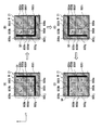
- FIG. 2 is an enlarged view showing VIa to VId portions of a substrate holding portion of each proximity exposure apparatus main body of FIG. (a)-(h) is a figure which shows the various modifications of a permite
- FIG. 10 is a partially exploded perspective view for explaining a proximity exposure apparatus applied to the exposure unit of FIG. 9. It is a front view of the proximity exposure apparatus shown in FIG. It is an expansion perspective view of the mask holding
- FIG. (A) to (D) are diagrams showing the suction state of the substrate when the substrate is stepped.
- FIGS. 10A to 10B are views showing a state in which different types of substrates are arranged on the front view of the substrate holding unit shown in FIG.
- the exposure unit 1 of the present invention includes a first proximity exposure apparatus body 2 that exposes a first layer, a second proximity exposure apparatus body 3 that exposes a second layer, and a third layer.
- an apparatus used for pre-processing and post-processing processes such as a coater, pre-alignment, and development, and a transport apparatus that transports the substrate are not shown.
- the first to fourth proximity exposure apparatus bodies 2, 3, 4, and 5 may be configured so that the suction surfaces of the substrate holding portions described later are different, only the first proximity exposure apparatus body 2 will be described below. Detailed description.
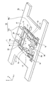
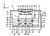
- the first proximity exposure apparatus body 2 includes a mask holding unit 10 that holds a mask M, a substrate holding unit 20 that holds a glass substrate (material to be exposed) W, and irradiation for pattern exposure.
- An illumination optical system 30 as a means, a substrate holding unit moving mechanism 40 that moves the substrate holding unit 20 in the X-axis, Y-axis, and Z-axis directions and adjusts the tilt of the substrate holding unit 20, a mask holding unit 10 and And an apparatus base 50 that supports the substrate holding part moving mechanism 40.
- substrate W a glass substrate W (hereinafter simply referred to as “substrate W”) is disposed to face the mask M, and a surface (on the opposite surface side of the mask M) for exposing and transferring a mask pattern drawn on the mask M. ) Is coated with a photosensitive agent.
- the mask M is made of fused quartz and has a rectangular shape.
- the illumination optical system 30 is, for example, a high-pressure mercury lamp 31 that is a light source for ultraviolet irradiation, and a concave mirror 32 that collects light emitted from the high-pressure mercury lamp 31.
- a high-pressure mercury lamp 31 that is a light source for ultraviolet irradiation
- a concave mirror 32 that collects light emitted from the high-pressure mercury lamp 31.
- optical integrators 33 which are switchably arranged near the focal point of the concave mirror 32, the plane mirrors 35 and 36 and the spherical mirror 37 for changing the direction of the optical path, and between the plane mirror 36 and the optical integrator 33.
- an exposure control shutter 34 that controls the opening and closing of the irradiation light path.
- the exposure control shutter 34 when the exposure control shutter 34 is controlled to be opened during exposure, the light emitted from the high-pressure mercury lamp 31 passes through the optical path L shown in FIG. 2 on the surfaces of the mask M and the substrate W. Irradiated perpendicularly to the surface, it is used as parallel light for pattern exposure. Thereby, the mask pattern of the mask M is exposed and transferred onto the substrate W.
- the mask holding unit 10 includes a mask holding unit base 11 in which a rectangular opening 11a is formed at the center, and an X axis and Y axis at the opening 11a of the mask holding unit base 11.
- a mask holding frame 12 that is mounted so as to be movable in the axial and ⁇ directions, a chuck portion 14 that is attached to the mask holding frame 12 and holds the mask M by suction, and the mask holding frame 12 and the chuck portion are connected to the X axis and the Y axis. , ⁇ direction, and a mask position adjusting mechanism 16 that adjusts the position of the mask M held by the mask holding frame 12.
- the mask holding unit base 11 is supported by a column 51 standing on the apparatus base 50 and a Z-axis moving device 52 provided at the upper end of the column 51 so as to be movable in the Z-axis direction, and above the substrate holding unit 20. Placed in.
- the Z-axis moving device 52 includes, for example, an electric actuator including a motor and a ball screw, a pneumatic cylinder, or the like, and moves the mask holding unit 10 up and down to a predetermined position by performing a simple vertical movement.
- the Z-axis moving device 52 is used for exchanging the mask M, cleaning the work chuck 21, and the like.
- the mask position adjusting mechanism 16 includes one Y-axis direction driving device 16y attached to one side along the X-axis direction of the mask holding frame 12 and two Xs attached to one side along the Y-axis direction of the mask holding frame 12.
- the mask position adjusting mechanism 16 moves the mask holding frame 12 in the Y-axis direction by driving one Y-axis direction driving device 16y, and drives the two X-axis direction driving devices 16x equally.
- the mask holding frame 12 is moved in the X-axis direction.
- the mask holding frame 12 is moved in the ⁇ direction (rotated about the Z axis) by driving one of the two X-axis direction driving devices 16x.
- a gap sensor 17 for measuring a gap between the opposing surfaces of the mask M and the substrate W and a mask M held by the chuck part 14 are attached.
- a mask alignment camera 18 for confirming the position is held so as to be movable in the X-axis and Y-axis directions via the moving mechanism 19 and are arranged in the mask holding frame 12.
- An aperture 38 is provided on the upper surface of the mask holding part base 11, as shown in FIG. 4, masking that shields both ends of the mask M as necessary at both ends in the X-axis direction of the opening 11 a of the mask holding part base 11.
- An aperture 38 is provided.
- the masking aperture 38 is movable in the X-axis direction by a masking aperture drive mechanism 39 including a motor, a ball screw, a linear guide, and the like, and adjusts the shielding area at both ends of the mask M.
- the masking aperture 38 may be provided not only at both ends in the X-axis direction of the opening 11a but also at both ends in the Y-axis direction of the opening 11a.
- the substrate holding unit 20 is installed on the substrate holding unit moving mechanism 40 and has a chucking surface 22 on the upper surface for holding the substrate W on the substrate holding unit 20. 21 is provided.
- the work chuck 21 holds the substrate W by vacuum suction.
- the substrate holding unit moving mechanism 40 includes a Y-axis feed mechanism 41 that moves the substrate holding unit 20 in the Y-axis direction, and an X-axis feed that moves the substrate holding unit 20 in the X-axis direction.
- a mechanism 42 and a Z-tilt adjustment mechanism 43 that finely moves the substrate holding unit 20 in the Z-axis direction while adjusting the tilt of the substrate holding unit 20 are provided.
- the Y-axis feed mechanism 41 includes a pair of linear guides 44 installed on the upper surface of the apparatus base 50 along the Y-axis direction, a Y-axis table 45 supported by the linear guide 44 so as to be movable in the Y-axis direction, And a Y-axis feed driving device 46 for moving the axis table 45 in the Y-axis direction. Then, by driving the motor 46c of the Y-axis feed driving device 46 and rotating the ball screw shaft 46b, the Y-axis table 45 is moved along the guide rail 44a of the linear guide 44 together with the ball screw nut 46a. The holding part 20 is moved in the Y-axis direction.
- the X-axis feed mechanism 42 includes a pair of linear guides 47 installed on the upper surface of the Y-axis table 45 along the X-axis direction, and an X-axis table 48 supported by the linear guide 47 so as to be movable in the X-axis direction. And an X-axis feed drive device 49 that moves the X-axis table 48 in the X-axis direction. Then, by driving the motor 49c of the X-axis feed driving device 49 and rotating the ball screw shaft 49b, the X-axis table 48 is moved along the guide rail 47a of the linear guide 47 together with a ball screw nut (not shown). Then, the substrate holding unit 20 is moved in the X-axis direction.
- the Z-tilt adjusting mechanism 43 includes a motor 43a installed on the X-axis table 48, a ball screw shaft 43b rotated by the motor 43a, and a wedge formed in a wedge shape and screwed to the ball screw shaft 43b.
- two Z-tilt adjustment mechanisms 43 are provided on one end side (front side in FIG. 1) in the X-axis direction of the X-axis table 48, and one set on the other end side (the rear side in FIG. A total of three units are installed (see FIG. 3), and each is driven and controlled independently.
- the number of Z-tilt adjustment mechanisms 43 installed is arbitrary.
- the wedge-shaped nut 43c is horizontally moved in the X-axis direction, and this horizontal movement is caused by the wedge-shaped nut 43c and the wedge portion 43d.
- the wedge portion 43d is finely moved in the Z direction by being converted into a highly precise vertical fine motion by the action of the slope. Accordingly, by driving the three Z-tilt adjustment mechanisms 43 by the same amount, the substrate holding unit 20 can be finely moved in the Z-axis direction, and the three Z-tilt adjustment mechanisms 43 can be independently operated. By driving, the tilt adjustment of the substrate holder 20 can be performed. As a result, the position of the substrate holding unit 20 in the Z axis and tilt direction can be finely adjusted so that the mask M and the substrate W face each other in parallel with a predetermined interval.
- the first proximity exposure apparatus main body 2 is provided with a laser length measuring device 60 which is a position measuring device for detecting the position of the substrate holder 20.
- the laser length measuring device 60 measures a moving distance of the substrate holding part 20 generated when the substrate holding part moving mechanism 40 is driven.
- the laser length measuring device 60 is fixed to a stay (not shown) and is arranged along the X-axis direction side surface of the substrate holding unit 20, and is fixed to the stay 71 and fixed to the substrate holding unit 20.
- the Y-axis mirror 65 disposed along the side surface in the Y-axis direction, and the X-axis direction end of the apparatus base 50 are irradiated with laser light (measurement light) on the X-axis mirror 64.
- the X-axis length measuring device 61, the yawing measuring device 62, and the Y-axis length measuring device 63 irradiate the X-axis mirror 64 and the Y-axis mirror 65 with the laser light applied to the X-axis measuring device.
- the position of the substrate holding unit 20 in the X axis and Y axis directions is measured with high accuracy.
- the position data in the X-axis direction is measured by the X-axis length measuring device 61, and the position in the ⁇ direction is measured by the yawing measuring device 62.
- the position of the substrate holding unit 20 is calculated by appropriately correcting the position in the X-axis direction, the Y-axis direction, and the ⁇ -direction measured by the laser length measuring device 60.
- FIG. 5A is a top view schematically showing the suction surface of the work chuck 21 of the first proximity exposure apparatus main body 2, and FIG. 5B is an enlarged view of a portion V in FIG. 5A.
- the central first adsorption region 80a and the outer second adsorption region 80b are partitioned by a quadrangular first partition wall 81a, and the second adsorption region 80b and the third adsorption region 80c outside thereof.
- the third suction region 80c and the fourth to seventh suction regions 80d, 80e, 80f, and 80g formed at the four locations outside the third suction region 80c are partitioned by a rectangular third partition wall 83a.
- the first suction region 80a is defined by the first partition wall 81a
- the second suction region 80b is defined between the first and second partition walls 81a and 82a
- the third partition wall 81a is defined by the third partition wall 81a.
- the suction region 80c is defined between the second and third partition walls 82a and 83a.
- the fourth to seventh suction regions 80d,..., 80g are defined by the third partition wall 83a and the peripheral wall 84a that is the outer peripheral edge of the suction surface 22.
- the shape of the peripheral edge portion 84a corresponds to the size of the rectangular substrate W, and suction is performed in the fourth to seventh suction regions 80d to 80g according to the orientation of the substrate W.
- a plurality of projections 85 having a height equal to the height of each partition wall 81a, 82a, 83a are formed in each suction region 80a, ..., 80g, and each partition wall 81a, 82a, 83a is formed.
- the protrusion 85 can contact the back surface of the substrate W.
- the part except each partition wall 81a, 82a, 83a and the protrusion 85 becomes the low part 86 of each adsorption
- the partition walls 81a, 82a, 83a and the protrusions 85 may be processed by cutting with an end mill or shot blasting.
- a plurality of positive and negative pressure holes 87a,..., 87g are opened on the surface of each low portion 86 in each adsorption region 80a,.
- vacuum suction is performed from the positive / negative pressure holes 87a,..., 87g, so that the low portions 86 of the suction regions 80a,.
- a space surrounded by 83a and the peripheral wall portion 84a and the back surface of the substrate W is set to a negative pressure.
- the space is opened to the atmosphere or positive pressure is introduced from the positive and negative pressure holes 87a,.
- the deflection can be reduced by gradually performing outward from the inner first adsorption region 80a.
- the substrate W when it is exposed, it may be performed in a state where vacuum suction is performed by the positive and negative pressure holes 87a,... 87g, but is performed in a state where the vacuum suction of each suction region is partially or wholly released. May be.
- the suction surface 22 has a plurality of pin holes (not shown) through which a plurality of pins (not shown) advanced from the suction surface 22 when the substrate W is transported to the work chuck 21 by a work loader (not shown). (Not shown) is formed.
- suction surface 22 has substantially the same outer dimensions in each of the proximity exposure apparatus bodies 2, 3, 4 and 5, as shown in FIG. 1, the positions of the outermost peripheral walls 84a,. The same applies to each of the proximity exposure apparatus bodies 2 to 5.
- the three partition walls 83a, ..., 83d are formed at different positions.
- FIG. 6 shows the VId portion of FIG. 1 when the substrate W is placed on the suction surface 22 of the work chuck 21 of the fourth proximity exposure apparatus body 5, and the first to third proximity exposure apparatus bodies 2 to 4. 1, the portions where the second and third partition walls 82a,..., 82c, 83a,.
- first to fourth proximity exposure apparatus bodies 2,..., 5 configured as described above, when the first to fourth layers are transferred to the substrate W, at the position of the partition wall, although the substrate is slightly distorted due to the influence of the temperature change, the positions of the partition walls 81a,... To 81d, 82a,..., 82d, 83a,. ,..., 5 are different from each other, so that the substrate W is not visually recognized as exposure unevenness, and variation in exposure profile can be suppressed. Note that the position of the substrate W where the peripheral walls 84a,..., 84d come in contact is outside the pattern region where the pattern is exposed and transferred to the substrate W. Even if the wall position is the same, exposure accuracy is not affected.
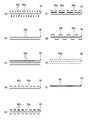
- the partition wall is formed by a linear continuous portion and the projection is formed by a square shape, but may be changed to various shapes as shown in FIGS.
- the partition wall 90 may be constituted by a continuous portion 90a and extending portions 90b extending on both sides of the continuous portion 90a in a direction perpendicular to the continuous portion 90a. Good. Thereby, the deflection of the non-contact portion of the substrate W in the vicinity of the partition wall 90 can be reduced, the gap amount between the mask M and the substrate W can be made more uniform, and exposure unevenness and exposure profile variation can be reduced. Can be suppressed.
- the partition wall 90 includes a continuous portion 90a and extending portions extending toward the protrusions 91 located on both sides of the continuous portion 90a. 90b.
- the extending portion 90b of the partition wall 90 is directed to an intermediate position between adjacent protrusions 91 in the direction in which the continuous portion 90a of the partition wall 90 extends. May extend.
- the extended portion 90b on one side of the continuous portion 90a extends toward the protrusion 91, and the extended portion 90b on the other side extends toward an intermediate position between the protrusions 91. You may do it.
- the continuous portion 90a between the extending portions 90b adjacent to each other in the extending direction of the continuous portion 90a is curved according to the shape of the end mill.
- the continuous part 90a may be connected not in linear form but in zigzag form.
- the extending portions 90b are formed on both sides of the continuous portion 90a so that their extending positions are different from each other.
- the tip of the extended portion 90 b extends so as to form the protrusion 91.
- the interval between the projections 91 located in the vicinity of the partition wall 90 is made shorter than the interval between the projections 91 located in a portion away from the partition wall 90.
- the distance between the partition wall 90 and the adjacent protrusion 91 is large, the non-contact portion is greatly bent and exposure unevenness may occur, but FIG. 7 (a) to FIG. 7 (c).
- the deflection of the non-contact portion can be reduced, and uneven exposure can be suppressed.
- the partition wall 90 includes a continuous portion 90a and a rectangular portion 90c extending from the continuous portion 90a in a direction orthogonal to the continuous portion 90a on both sides of the continuous portion 90a. It may be configured, or may be configured by two or three continuous portions 90a as shown in FIGS. 8 (b) and 8 (c). By configuring the partition wall 90 with a plurality of continuous portions 90a in this way, it is possible to reduce the deflection of the non-contact portion by dispersing the contact portion with the substrate W and making it less susceptible to temperature. .
- the partition wall 90 includes a continuous portion 90a and a rectangular portion extending discontinuously along the continuous portion 90a on one side or both sides of the continuous portion 90a. 90d, 90e, and wavy line part 90f may be sufficient. That is, the partition wall 90 may be symmetric with respect to the continuous portion 90a or may be asymmetric.
- the partition wall 90 is arranged in a plurality of rows so that the protrusions 90g such as a circle or a square are filled in the gaps between the adjacent protrusions 90g in the direction in which the partition wall 90 is formed.
- adjacent suction regions may be partitioned by concentrating the discontinuous protrusions 90g and 90i by narrowing the interval between the protrusions 90i.
- each exposure apparatus main body is not required to be completely overlapped and contacted at the same position as the back surface of the substrate, and may be partially overlapped and contacted.
- the shape of the partition wall 90 mentioned above can be used in combination as appropriate.
- the suction surfaces of the proximity exposure apparatus main bodies have different configurations.
- the width of the peripheral edge on the outside of the pattern area is formed wide so that the suction surfaces have the same configuration, and the substrate attachment position May be attached with a slight shift between the plurality of proximity exposure apparatus main bodies.
- the partition wall comes into contact with the back surface of the substrate at a different position for each exposure apparatus body, and it is possible to suppress occurrence of exposure unevenness and exposure profile variations.
- the width of the peripheral portion is designed to be wider than the most shifted amount between the plurality of proximity exposure apparatus main bodies.
- the exposure unit 1 of the present invention includes a first proximity exposure apparatus body 2 that exposes a first layer, a second proximity exposure apparatus body 3 that exposes a second layer, and a third layer.
- an apparatus used for pre-processing and post-processing processes such as a coater, pre-alignment, and development, and a transport apparatus that transports the substrate are not shown.
- the first to fourth proximity exposure apparatus bodies 2, 3, 4, and 5 may be configured so that the suction surfaces of the substrate holding portions described later are different, only the first proximity exposure apparatus body 2 will be described below. Detailed description.
- the first proximity exposure apparatus body 2 includes a mask holding unit 10 that holds a mask M, a substrate holding unit (substrate stage) 20 that holds a glass substrate (material to be exposed) W, and a pattern.
- An illumination optical system 30 that emits exposure light for exposure, a substrate holding unit moving mechanism 40 that moves the substrate holding unit 20 in the X-axis, Y-axis, and Z-axis directions and adjusts the tilt of the substrate holding unit 20;
- an apparatus base 50 that supports the mask holding unit 10 and the substrate holding unit moving mechanism 40.
- substrate W a glass substrate W (hereinafter simply referred to as “substrate W”) is disposed to face the mask M, and a surface (on the opposite surface side of the mask M) for exposing and transferring a mask pattern drawn on the mask M. ) Is coated with a photosensitive agent.
- the mask M is made of fused silica and is formed in a rectangular shape.
- the illumination optical system 30 is, for example, a high-pressure mercury lamp 31 that is a light source for ultraviolet irradiation, and a concave mirror 32 that collects light emitted from the high-pressure mercury lamp 31.
- a high-pressure mercury lamp 31 that is a light source for ultraviolet irradiation
- a concave mirror 32 that collects light emitted from the high-pressure mercury lamp 31.
- optical integrators 33 which are switchably arranged near the focal point of the concave mirror 32, the plane mirrors 35 and 36 and the spherical mirror 37 for changing the direction of the optical path, and between the plane mirror 36 and the optical integrator 33.
- an exposure control shutter 34 that controls the opening and closing of the irradiation light path.
- the exposure control shutter 34 when the exposure control shutter 34 is controlled to be opened at the time of exposure, the light emitted from the high-pressure mercury lamp 31 is held by the mask holding unit 10 through the optical path L shown in FIG. Irradiated as parallel light for pattern exposure perpendicularly to the surface of the substrate M held by the mask M and the substrate holding unit 20. Thereby, the mask pattern of the mask M is exposed and transferred onto the substrate W.
- the mask holding unit 10 includes a mask holding unit base 11 in which a rectangular opening 11a is formed at the center, and an X axis and Y axis at the opening 11a of the mask holding unit base 11.
- a mask holding frame 12 that is mounted so as to be movable in the axial and ⁇ directions, a chuck portion 14 that is attached to the mask holding frame 12 and holds the mask M by suction, and the mask holding frame 12 and the chuck portion are connected to the X axis and the Y axis. , ⁇ direction, and a mask position adjusting mechanism 16 that adjusts the position of the mask M held by the mask holding frame 12.
- the mask holding unit base 11 is supported by a column 51 standing on the apparatus base 50 and a Z-axis moving device 52 provided at the upper end of the column 51 so as to be movable in the Z-axis direction, and above the substrate holding unit 20. Placed in.
- the Z-axis moving device 52 includes, for example, an electric actuator including a motor and a ball screw, a pneumatic cylinder, or the like, and moves the mask holding unit 10 up and down to a predetermined position by performing a simple vertical movement.
- the Z-axis moving device 52 is used for exchanging the mask M, cleaning the work chuck 21, and the like.
- the mask position adjusting mechanism 16 includes one Y-axis direction driving device 16y attached to one side along the X-axis direction of the mask holding frame 12 and two Xs attached to one side along the Y-axis direction of the mask holding frame 12.
- the mask position adjusting mechanism 16 moves the mask holding frame 12 in the Y-axis direction by driving one Y-axis direction driving device 16y, and drives the two X-axis direction driving devices 16x equally.
- the mask holding frame 12 is moved in the X-axis direction.
- the mask holding frame 12 is moved in the ⁇ direction (rotated about the Z axis) by driving one of the two X-axis direction driving devices 16x.
- a gap sensor 17 for measuring a gap between the opposing surfaces of the mask M and the substrate W, and a mask M held by the chuck unit 14 are attached.
- a mask alignment camera 18 for confirming the position is held so as to be movable in the X-axis and Y-axis directions via the moving mechanism 19 and are arranged in the mask holding frame 12.
- An aperture 38 is provided on the upper surface of the mask holding part base 11, as shown in FIG. 12, masking that shields both ends of the mask M as necessary at both ends in the X-axis direction of the opening 11 a of the mask holding part base 11.
- An aperture 38 is provided.
- the masking aperture 38 is movable in the X-axis direction by a masking aperture drive mechanism 39 including a motor, a ball screw, a linear guide, and the like, and adjusts the shielding area at both ends of the mask M.
- the masking aperture 38 may be provided not only at both ends in the X-axis direction of the opening 11a but also at both ends in the Y-axis direction of the opening 11a.
- the substrate holding unit 20 is installed on the substrate holding unit moving mechanism 40 and has a work chuck having an adsorption surface 22 for holding the substrate W on the substrate holding unit 20 on the upper surface. 21 is provided.
- the work chuck 21 holds the substrate W by vacuum suction.
- the substrate holding unit moving mechanism 40 includes a Y-axis feed mechanism 41 that moves the substrate holding unit 20 in the Y-axis direction, and an X-axis feed that moves the substrate holding unit 20 in the X-axis direction.
- a mechanism 42 and a Z-tilt adjustment mechanism 43 that finely moves the substrate holding unit 20 in the Z-axis direction while adjusting the tilt of the substrate holding unit 20 are provided.
- the Y-axis feed mechanism 41 includes a pair of linear guides 44 installed on the upper surface of the apparatus base 50 along the Y-axis direction, a Y-axis table 45 supported by the linear guide 44 so as to be movable in the Y-axis direction, And a Y-axis feed driving device 46 for moving the axis table 45 in the Y-axis direction. Then, by driving the motor 46c of the Y-axis feed driving device 46 and rotating the ball screw shaft 46b, the Y-axis table 45 is moved along the guide rail 44a of the linear guide 44 together with the ball screw nut 46a. The holding part 20 is moved in the Y-axis direction.
- the X-axis feed mechanism 42 includes a pair of linear guides 47 installed on the upper surface of the Y-axis table 45 along the X-axis direction, and an X-axis table 48 supported by the linear guide 47 so as to be movable in the X-axis direction. And an X-axis feed drive device 49 that moves the X-axis table 48 in the X-axis direction. Then, by driving the motor 49c of the X-axis feed driving device 49 and rotating the ball screw shaft 49b, the X-axis table 48 is moved along the guide rail 47a of the linear guide 47 together with a ball screw nut (not shown). Then, the substrate holding unit 20 is moved in the X-axis direction.
- the Z-tilt adjusting mechanism 43 includes a motor 43a installed on the X-axis table 48, a ball screw shaft 43b rotated by the motor 43a, and a wedge formed in a wedge shape and screwed to the ball screw shaft 43b.
- two Z-tilt adjustment mechanisms 43 are provided on one end side (front side in FIG. 9) of the X-axis table 48 and one on the other end side (the rear side in FIG. (See FIG. 11.) A total of three are installed, and each is independently driven and controlled.
- the number of Z-tilt adjustment mechanisms 43 installed is arbitrary.
- the wedge-shaped nut 43c is horizontally moved in the X-axis direction, and this horizontal movement is caused by the wedge-shaped nut 43c and the wedge portion 43d.
- the wedge portion 43d is finely moved in the Z direction by being converted into a highly precise vertical fine motion by the action of the slope. Accordingly, by driving the three Z-tilt adjustment mechanisms 43 by the same amount, the substrate holding unit 20 can be finely moved in the Z-axis direction, and the three Z-tilt adjustment mechanisms 43 can be independently operated. By driving, the tilt adjustment of the substrate holder 20 can be performed. As a result, the position of the substrate holding unit 20 in the Z axis and tilt direction can be finely adjusted so that the mask M and the substrate W face each other in parallel with a predetermined interval.
- the first proximity exposure apparatus main body 2 is provided with a laser length measuring device 60 which is a position measuring device for detecting the position of the substrate holding unit 20.
- the laser length measuring device 60 measures a moving distance of the substrate holding part 20 generated when the substrate holding part moving mechanism 40 is driven.
- the laser length measuring device 60 is fixed to a stay (not shown) and is arranged along the X-axis direction side surface of the substrate holding unit 20, and is fixed to the stay 71 and fixed to the substrate holding unit 20.
- the Y-axis mirror 65 disposed along the side surface in the Y-axis direction, and the X-axis direction end of the apparatus base 50 are irradiated with laser light (measurement light) on the X-axis mirror 64.
- the X-axis length measuring device 61, the yawing measuring device 62, and the Y-axis length measuring device 63 irradiate the X-axis mirror 64 and the Y-axis mirror 65 with the laser light applied to the X-axis measuring device.
- the position of the substrate holding unit 20 in the X axis and Y axis directions is measured with high accuracy.
- the position data in the X-axis direction is measured by the X-axis length measuring device 61, and the position in the ⁇ direction is measured by the yawing measuring device 62.
- the position of the substrate holder 20 is calculated by appropriately correcting the position in the X-axis direction, the Y-axis direction, and the ⁇ -direction measured by the laser length measuring device 60.
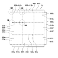
- FIG. 13 is a top view schematically showing the suction surface of the work chuck 21 of the first proximity exposure apparatus main body 2.
- the suction surface 22 of the work chuck 21 is formed with 13 independent suction regions, that is, first to thirteenth suction regions 800a,..., 800m.
- the first suction region 800a is partitioned by a quadrangular first partition wall 810a, and the second to ninth suction regions 800b to 800i are sequentially adjacent to the first suction region 800a to form the partition walls 810b to 810b. It is partitioned by 810i and arranged in a matrix.
- the partition wall 810b of the second suction region 800b adjacent to the partition wall 810a of the first suction region 800a is a common wall at the adjacent portion.
- the partition wall 810d of the fourth suction region 800d adjacent to the partition wall 810a of the first suction region 800a is also a common wall at the adjacent portion. The same applies to other suction areas.
- a tenth peripheral suction area 800j to a thirteenth peripheral suction area 810m are partitioned by partition walls 810j to 810m, and are formed in a rectangular shape.
- the partition wall 810g of the seventh suction region 800g adjacent to the partition wall 810j of the tenth peripheral suction region 800j, the partition wall 810h of the eighth suction region 800h, and the partition wall 810i of the ninth suction region 80i are adjacent portions. It is considered as a common wall. The same applies to other surrounding adsorption regions.
- the tenth peripheral suction region 800j to the thirteenth peripheral suction region 800m correspond to the size of the rectangular substrate W, and are used according to the orientation of the substrate W.
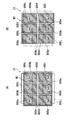
- FIG. 14 (A) to (D) are enlarged views of each of the A part, the B part, the C part, and the D part of FIG.
- a plurality of projections 85 having a height equal to the height of each partition wall 810a,..., 810m are formed in each suction region 800a,. , 81m and the projection 85 can contact the back surface of the substrate W.
- the part except each partition wall 810a, ..., 810m and protrusion 85 is the low part 86 of each adsorption
- the partition walls 810a,..., 810m and the projections 85 may be processed by end milling or shot blasting.
- a plurality of positive and negative pressure holes 87 are opened on the surface of each low portion 86 in each adsorption region 800a,..., 800m.
- vacuum suction is performed from the positive and negative pressure holes 87, so that the low portions 86 of the suction regions 800a,..., 800m, the partition walls 810a,.
- a space surrounded by the suction regions 800j,..., 800m and the back surface of the substrate W is set to a negative pressure.
- the space is opened to the atmosphere or a positive pressure is introduced from the positive / negative pressure hole 87 in order to easily separate the substrate W.
- FIG. 15 (B) shows the substrate W (solid line) placed on the suction surface 22 (dashed line) of the work chuck 21 of the first proximity exposure apparatus body 2. Further, the hatched portion of the substrate W in FIG. 15B displays the cells Se1 to Se4 to be exposed.
- the substrate W is used in a so-called vertical arrangement, and the first adsorption region 800a to the ninth adsorption region 800i, the tenth peripheral adsorption region 800j, and the twelfth peripheral adsorption region 800l are used as the adsorption regions. used.
- suction regions are controlled by a suction control unit 70a (see FIG. 10) provided in the control unit 70 (see FIG. 10).
- the suction controller 70a controls the suction area corresponding to the irradiation area of the exposure light independently of the other suction areas.
- the suction area corresponding to the exposure light irradiation area may be controlled to be non-adsorption, and the suction area corresponding to the exposure light irradiation area may be controlled to be decompressed from other suction areas.
- the adsorption control of the substrate W when the cells Se1 to Se4 of the substrate W are exposed will be described with reference to FIGS.
- the cell Se1 is exposed by irradiating the cell Se1 with exposure light.
- the first suction region 80a, the second suction region 800b, the fourth suction region 800d, and the fifth suction region 800e immediately below the cell Se1 (exposure light irradiation area) are controlled to be in a non-suction state.
- the ninth suction region 800i is controlled to the suction state.
- the tenth peripheral suction region 800j and the twelfth peripheral suction region 800l may or may not be suctioned. As described above, by not sucking the suction region immediately below the exposure light irradiation area, it is possible to avoid distortion of the substrate due to suction.
- the substrate holder 20 is stepped in the X-axis direction by the substrate holder moving mechanism 40, and as shown in FIG. 16B, the exposure light is irradiated to the cell Se2, thereby exposing the cell Se2.
- the third suction region 800c, the second suction region 800b, the sixth suction region 800f, and the fifth suction region 800e immediately below the cell Se2 are controlled to be in a non-suction state. Is done.
- the ninth suction region 800i is controlled to the suction state. Note that this suction region switching is performed after the exposure of the cell Se1 and before the step movement to the cell Se2. This prevents the substrate W from being displaced during the step.
- the substrate holder 20 is stepped in the Y-axis direction by the substrate holder moving mechanism 40, and as shown in FIG. 16C, the exposure light is irradiated to the cell Se3, so that the cell Se3 is exposed.
- the ninth suction region 800i, the eighth suction region 800h, the sixth suction region 800f, and the fifth suction region 800e immediately below the cell Se3 are controlled to be in a non-suction state. Is done.
- the twelfth suction region 800l is controlled to the suction state.
- the substrate holder 20 is stepped in the X-axis direction by the substrate holder moving mechanism 40, and as shown in FIG. 16D, exposure light is irradiated to the cell Se4, so that the cell Se4 is exposed.
- the seventh suction region 800g, the eighth suction region 800h, the fourth suction region 800d, and the fifth suction region 800e immediately below the cell Se4 are controlled to be in a non-suction state. Is done.
- the ninth suction region 800i is controlled to the suction state.
- region was switched before the step, you may switch an adsorption
- the seventh adsorption region 800g, the eighth adsorption region 800h, and the ninth adsorption region 800i are always in the adsorption state.
- the suction control is switched from the first suction region 800f to the first suction region 800a and the fourth suction region 800d.
- FIGS. 17 (A) and 17 (B) four cells (so-called four-sided placement) are exposed on one substrate W, but the present invention is not limited to this and can be applied to all types of placement.
- FIG. 16A shows a six-sided substrate W (a substrate that is long in the horizontal direction) placed horizontally, and suction during exposure is performed in the same manner as in the above embodiment.
- the eleventh surrounding suction region 800k and the thirteenth surrounding suction region 800m are used.
- FIG. 17B shows a six-sided substrate W (long substrate in the vertical direction) placed vertically, and suction during exposure is performed in the same manner as in the above embodiment.
- the tenth peripheral suction region 800j and the twelfth peripheral suction region 800l are used.
- the suction surface 22 has a plurality of pin holes (not shown) through which a plurality of pins (not shown) advanced from the suction surface 22 when the substrate W is transported to the work chuck 21 by a work loader (not shown). (Not shown) is formed.
- first to fourth proximity exposure apparatus bodies 2,..., 5 configured as described above, when the first to fourth layers are transferred to the substrate W, at the position of the partition wall, although the substrate is slightly distorted due to the influence of the temperature change, the substrate is not distorted by adsorbing the substrate, so that it is not visually recognized as uneven exposure on the substrate W, and variations in the exposure profile occur. Can be suppressed.
- this invention is not limited to each embodiment mentioned above, In the range which does not deviate from the summary of this invention, it can change suitably.
- the first to ninth suction areas 800a to 800i are formed in a wavy shape in which the partition walls 810a to 810i are non-linear, and the peripheral suction areas 800j,. , 810m is formed by a continuous portion of a linear shape, but the first to ninth suction regions 800a to 800i form partition walls 810a to 810i in a straight line, and the surrounding suction regions 800j,.
- the 800 m partition wall surrounding adsorption region 810j,..., 810m may be formed of a continuous portion of a wave shape that is non-linear.
- each protrusion was formed in a circular shape, it may be a square shape, and various shapes are applicable.
Landscapes
- Physics & Mathematics (AREA)
- General Physics & Mathematics (AREA)
- Life Sciences & Earth Sciences (AREA)
- Sustainable Development (AREA)
- Exposure And Positioning Against Photoresist Photosensitive Materials (AREA)
- Container, Conveyance, Adherence, Positioning, Of Wafer (AREA)
- Exposure Of Semiconductors, Excluding Electron Or Ion Beam Exposure (AREA)
Abstract
Description
以下、本発明の第1実施例に係る露光ユニット及び基板の露光方法について、図面に基づいて詳細に説明する。
(Z軸回りの回転)させる。
[第2実施例]
まず、図16(A)に示すように、露光用光がセルSe1に照射されることで、セルSe1が露光されるが。この時にセルSe1直下(露光用光照射エリア)の第1の吸着領域80a、第2の吸着領域800b、第4の吸着領域800d及び第5の吸着領域800eは非吸着状態に制御される。これに対し、セルSe1以外(露光用光照射エリア)を示すL字ライン部Q1の第3の吸着領域800c、第6の吸着領域800f、第7の吸着領域800g、第8の吸着領域800h及び第9の吸着領域800iは吸着状態に制御される。この場合に、第10の周囲吸着領域800j及び第12の周囲吸着領域800lは吸着を行っても良いし行わなくとも良い。このように、露光用光照射エリア直下の吸着領域の吸着を行わないことで、吸着による基板の歪が回避可能となる。
尚、この吸着領域の切り替えは、セルSe1の露光終了後、セルSe2へのステップ移動前に行われる。こうすることで、ステップ時に基板Wがずれてしまうことが防止される。
例えば、セルSe1からセルSe2へのステップ時には、第7の吸着領域800g、第8の吸着領域800h及び第9の吸着領域800iについては常時吸着状態のままなので、第3の吸着領域800c、第6の吸着領域800fから第1の吸着領域800a、第4の吸着領域800dに吸着制御を切り替えることとなる。
2 第1の近接露光装置本体
3 第2の近接露光装置本体
4 第3の近接露光装置本体
5 第4の近接露光装置本体
10 マスク保持部
12b 開口
14 チャック部
20 基板保持部
21 ワークチャック
22 吸着面
80a 第1の吸着領域
80b 第2の吸着領域
80c 第3の吸着領域
80d 第4の吸着領域
80e 第5の吸着領域
80f 第6の吸着領域
80g 第7の吸着領域
81a,81b,81c,81d 第1の仕切り壁
82a,82b,82c,82d 第2の仕切り壁
83a,83b,83c,83d 第3の仕切り壁
800a 第1の吸着領域
800b 第2の吸着領域
800c 第3の吸着領域
800d 第4の吸着領域
800e 第5の吸着領域
800f 第6の吸着領域
800g 第7の吸着領域
800h 第8の吸着領域
800i 第9の吸着領域
800j 第10の吸着領域
800k 第11の吸着領域
800l 第12の吸着領域
800m 第13の吸着領域
810a 第1の仕切り壁
810b 第2の仕切り壁
810c 第3の仕切り壁
810d 第4の仕切り壁
810e 第5の仕切り壁
810f 第6の仕切り壁
810g 第7の仕切り壁
810h 第8の仕切り壁
810i 第9の仕切り壁
810j 第10の周囲仕切り壁
810k 第11の周囲仕切り壁
810l 第12の周囲仕切り壁
810m 第13の周囲仕切り壁
M マスク
W ガラス基板(被露光材)
Claims (6)
- 複数のマスクのパターンを基板に順次露光転写する露光ユニットであって、
前記露光ユニットは、
前記パターンを有するマスクを保持するマスク保持部と、
前記基板を吸着して保持する吸着面を有する基板保持部と、
露光用光を照射する照射部と、
を有し、前記露光用光を照射することで前記基板上に前記マスクのパターンを露光転写する複数の露光装置本体を備え、
前記基板保持部の吸着面には、
隣り合う吸着領域を仕切るために形成され、前記基板の裏面に当接可能な仕切り壁と、
前記各吸着領域において前記基板の裏面に当接可能な複数の突起と、が設けられ、
前記複数の露光装置本体の各基板保持部の吸着面は、略同一外形寸法を有するとともに、前記各基板保持部の仕切り壁は、前記露光装置本体毎に異なる位置に形成されることを特徴とする露光ユニット。 - 前記基板保持部の吸着面には、前記各吸着領域が吸着又は非吸着になるよう制御する吸着制御部が設けられており、
前記吸着制御部は前記露光用光の照射エリアに対応する吸着領域を他の吸着領域とは独立に制御する請求項1記載の前記露光ユニット。 - 前記吸着制御部は前記照射エリアに対応する前記吸着領域が非吸着になるように制御する請求項2記載の前記露光ユニット。
- 前記吸着制御部は前記露光用光の照射エリアに対応する吸着領域が他の吸着領域より減圧となるよう制御する請求項2記載の前記露光ユニット。
- パターンを有するマスクを保持するマスク保持部と、基板を吸着して保持する吸着面を有する基板保持部と、露光用光を照射する照射部とを有し、前記露光用光を照射することで前記基板上に前記マスクのパターンを露光転写する複数の露光装置本体を用いて、前記各マスクのパターンを前記基板に順次露光する基板の露光方法であって、前記露光方法は、
前記吸着面の隣り合う吸着領域を仕切る仕切り壁が前記露光装置本体毎に異なる位置で前記基板の裏面と当接するように、前記複数の露光装置本体によって前記基板を順次露光する工程を有することを特徴とする露光方法。 - 前記露光用光の照射エリアに対応する吸着領域が他の吸着領域とは独立に制御される請求項5に記載の前記露光方法。
Priority Applications (3)
| Application Number | Priority Date | Filing Date | Title |
|---|---|---|---|
| KR1020127013454A KR101415386B1 (ko) | 2009-11-25 | 2010-11-24 | 노광 유닛 및 기판의 노광 방법 |
| CN2010800023874A CN102203677B (zh) | 2009-11-25 | 2010-11-24 | 曝光装置以及基板的曝光方法 |
| JP2011543275A JP5517171B2 (ja) | 2009-11-25 | 2010-11-24 | 露光ユニット及び基板の露光方法 |
Applications Claiming Priority (4)
| Application Number | Priority Date | Filing Date | Title |
|---|---|---|---|
| JP2009-267918 | 2009-11-25 | ||
| JP2009267918 | 2009-11-25 | ||
| JP2010-016087 | 2010-01-28 | ||
| JP2010016087 | 2010-01-28 |
Publications (1)
| Publication Number | Publication Date |
|---|---|
| WO2011065386A1 true WO2011065386A1 (ja) | 2011-06-03 |
Family
ID=44066491
Family Applications (1)
| Application Number | Title | Priority Date | Filing Date |
|---|---|---|---|
| PCT/JP2010/070946 Ceased WO2011065386A1 (ja) | 2009-11-25 | 2010-11-24 | 露光ユニット及び基板の露光方法 |
Country Status (5)
| Country | Link |
|---|---|
| JP (1) | JP5517171B2 (ja) |
| KR (1) | KR101415386B1 (ja) |
| CN (1) | CN102203677B (ja) |
| TW (1) | TWI468875B (ja) |
| WO (1) | WO2011065386A1 (ja) |
Cited By (1)
| Publication number | Priority date | Publication date | Assignee | Title |
|---|---|---|---|---|
| EP2793083A1 (en) * | 2013-04-01 | 2014-10-22 | Canon Kabushiki Kaisha | Holder, lithography apparatus, and method of manufacturing article |
Families Citing this family (3)
| Publication number | Priority date | Publication date | Assignee | Title |
|---|---|---|---|---|
| CN103676488B (zh) * | 2012-09-10 | 2016-02-03 | 上海微电子装备有限公司 | 掩模交接机构及具有该掩模交接机构的掩模台 |
| JP6342570B1 (ja) * | 2016-12-27 | 2018-06-13 | 株式会社アルバック | ギャップ計測方法 |
| CN107272351A (zh) * | 2017-07-28 | 2017-10-20 | 武汉华星光电技术有限公司 | 承载装置及具有该承载装置的曝光设备 |
Citations (10)
| Publication number | Priority date | Publication date | Assignee | Title |
|---|---|---|---|---|
| JPH02191317A (ja) * | 1989-01-19 | 1990-07-27 | Tokyo Electron Ltd | レジスト処理装置およびレジスト処理方法 |
| JPH0629130Y2 (ja) * | 1988-08-31 | 1994-08-10 | 河西工業株式会社 | 車両用インシュレータ |
| JPH09134949A (ja) * | 1995-10-27 | 1997-05-20 | Samsung Aerospace Ind Ltd | 真空チャック |
| JP2000012663A (ja) * | 1998-06-17 | 2000-01-14 | Nikon Corp | 基板保持方法及び装置、及びそれを備えた露光装置 |
| JP2006054364A (ja) * | 2004-08-13 | 2006-02-23 | Nikon Corp | 基板吸着装置、露光装置 |
| JP2006235018A (ja) * | 2005-02-23 | 2006-09-07 | Hitachi High-Technologies Corp | 露光装置、露光方法、及び表示用パネル基板の製造方法 |
| JP2007148462A (ja) * | 2007-03-19 | 2007-06-14 | Nsk Ltd | ワークチャック及びその制御方法 |
| JP2007219537A (ja) * | 2007-03-19 | 2007-08-30 | Nsk Ltd | ワークチャック及びその制御方法 |
| JP2009188427A (ja) * | 2009-05-21 | 2009-08-20 | Dainippon Printing Co Ltd | 露光機および露光機用チャックステージ |
| JP2009258197A (ja) * | 2008-04-14 | 2009-11-05 | Hitachi High-Technologies Corp | プロキシミティ露光装置、プロキシミティ露光装置の基板吸着方法、及び表示用パネル基板の製造方法 |
Family Cites Families (8)
| Publication number | Priority date | Publication date | Assignee | Title |
|---|---|---|---|---|
| JPH0629130A (ja) * | 1992-07-13 | 1994-02-04 | Toshiba Corp | 変圧器 |
| JPH0629130U (ja) * | 1992-09-09 | 1994-04-15 | 日鉄セミコンダクター株式会社 | ウエハホルダの組合わせ |
| JP4288694B2 (ja) * | 2001-12-20 | 2009-07-01 | 株式会社ニコン | 基板保持装置、露光装置及びデバイス製造方法 |
| JP2005310933A (ja) * | 2004-04-20 | 2005-11-04 | Nikon Corp | 基板保持部材、露光装置及びデバイス製造方法 |
| KR101187611B1 (ko) * | 2004-09-01 | 2012-10-08 | 가부시키가이샤 니콘 | 기판 홀더, 스테이지 장치, 및 노광 장치 |
| EP2768016B1 (en) * | 2005-12-08 | 2017-10-25 | Nikon Corporation | Exposure apparatus and method |
| JP2009212344A (ja) * | 2008-03-05 | 2009-09-17 | Nsk Ltd | ワークチャック、露光装置及びフラットパネル製造方法 |
| JP2009267918A (ja) * | 2008-04-28 | 2009-11-12 | Panasonic Corp | ステレオカメラ、ステレオ撮像方法及びそのプログラム |
-
2010
- 2010-11-24 WO PCT/JP2010/070946 patent/WO2011065386A1/ja not_active Ceased
- 2010-11-24 JP JP2011543275A patent/JP5517171B2/ja not_active Expired - Fee Related
- 2010-11-24 CN CN2010800023874A patent/CN102203677B/zh not_active Expired - Fee Related
- 2010-11-24 KR KR1020127013454A patent/KR101415386B1/ko not_active Expired - Fee Related
- 2010-11-25 TW TW99140850A patent/TWI468875B/zh not_active IP Right Cessation
Patent Citations (10)
| Publication number | Priority date | Publication date | Assignee | Title |
|---|---|---|---|---|
| JPH0629130Y2 (ja) * | 1988-08-31 | 1994-08-10 | 河西工業株式会社 | 車両用インシュレータ |
| JPH02191317A (ja) * | 1989-01-19 | 1990-07-27 | Tokyo Electron Ltd | レジスト処理装置およびレジスト処理方法 |
| JPH09134949A (ja) * | 1995-10-27 | 1997-05-20 | Samsung Aerospace Ind Ltd | 真空チャック |
| JP2000012663A (ja) * | 1998-06-17 | 2000-01-14 | Nikon Corp | 基板保持方法及び装置、及びそれを備えた露光装置 |
| JP2006054364A (ja) * | 2004-08-13 | 2006-02-23 | Nikon Corp | 基板吸着装置、露光装置 |
| JP2006235018A (ja) * | 2005-02-23 | 2006-09-07 | Hitachi High-Technologies Corp | 露光装置、露光方法、及び表示用パネル基板の製造方法 |
| JP2007148462A (ja) * | 2007-03-19 | 2007-06-14 | Nsk Ltd | ワークチャック及びその制御方法 |
| JP2007219537A (ja) * | 2007-03-19 | 2007-08-30 | Nsk Ltd | ワークチャック及びその制御方法 |
| JP2009258197A (ja) * | 2008-04-14 | 2009-11-05 | Hitachi High-Technologies Corp | プロキシミティ露光装置、プロキシミティ露光装置の基板吸着方法、及び表示用パネル基板の製造方法 |
| JP2009188427A (ja) * | 2009-05-21 | 2009-08-20 | Dainippon Printing Co Ltd | 露光機および露光機用チャックステージ |
Cited By (2)
| Publication number | Priority date | Publication date | Assignee | Title |
|---|---|---|---|---|
| EP2793083A1 (en) * | 2013-04-01 | 2014-10-22 | Canon Kabushiki Kaisha | Holder, lithography apparatus, and method of manufacturing article |
| US9104108B2 (en) | 2013-04-01 | 2015-08-11 | Canon Kabushiki Kaisha | Holder, lithography apparatus, and method of manufacturing article |
Also Published As
| Publication number | Publication date |
|---|---|
| KR20120091241A (ko) | 2012-08-17 |
| TWI468875B (zh) | 2015-01-11 |
| JP5517171B2 (ja) | 2014-06-11 |
| KR101415386B1 (ko) | 2014-07-04 |
| TW201126280A (en) | 2011-08-01 |
| CN102203677B (zh) | 2013-11-06 |
| JPWO2011065386A1 (ja) | 2013-04-18 |
| CN102203677A (zh) | 2011-09-28 |
Similar Documents
| Publication | Publication Date | Title |
|---|---|---|
| US20090033899A1 (en) | Exposure apparatus, exposure method, and method for manufacturing display panel substrate | |
| WO2011158760A1 (ja) | 露光装置 | |
| JP5517171B2 (ja) | 露光ユニット及び基板の露光方法 | |
| JP4881407B2 (ja) | リソグラフィ装置、レチクル交換ユニットおよびデバイス製造方法 | |
| JP4942625B2 (ja) | 近接露光装置及び近接露光方法 | |
| JP5674197B2 (ja) | 近接露光装置及び近接露光方法 | |
| JP6655753B2 (ja) | 照明源としてのマイクロledアレイ | |
| US20180188655A1 (en) | Micro led array as illumination system | |
| JP5225396B2 (ja) | 露光装置、露光方法、及び基板製造方法 | |
| JP6037199B2 (ja) | 露光装置及び露光方法 | |
| JP4693347B2 (ja) | 露光用シャッター、露光装置、露光方法、及び基板製造方法 | |
| JP2011191755A (ja) | 露光方法及び基板の製造方法並びに露光装置 | |
| KR20070082847A (ko) | 평면판의 유지체 | |
| JP2023039062A (ja) | ステージ装置、露光装置、及び物品の製造方法 | |
| JP2012189800A (ja) | 近接露光装置 | |
| JP2013033261A (ja) | ワークチャック、ワーク保持方法及び露光装置 | |
| JP2008185946A (ja) | 露光装置 | |
| JP2008191404A (ja) | 基板搬送装置、ステージ装置、及びパターン形成装置 | |
| JP2009212344A (ja) | ワークチャック、露光装置及びフラットパネル製造方法 | |
| KR20250101256A (ko) | 기판 처리 방법 및 기판 처리 장치 | |
| JP5352433B2 (ja) | 露光装置 | |
| JP2012252212A (ja) | 露光装置及び露光方法 | |
| KR20240065949A (ko) | 기판 처리 방법 | |
| CN121620102A (zh) | 基板处理方法和基板处理装置 | |
| JP2009158986A (ja) | 露光装置、露光方法、及び基板製造方法 |
Legal Events
| Date | Code | Title | Description |
|---|---|---|---|
| WWE | Wipo information: entry into national phase |
Ref document number: 201080002387.4 Country of ref document: CN |
|
| 121 | Ep: the epo has been informed by wipo that ep was designated in this application |
Ref document number: 10833232 Country of ref document: EP Kind code of ref document: A1 |
|
| WWE | Wipo information: entry into national phase |
Ref document number: 2011543275 Country of ref document: JP |
|
| ENP | Entry into the national phase |
Ref document number: 20127013454 Country of ref document: KR Kind code of ref document: A |
|
| NENP | Non-entry into the national phase |
Ref country code: DE |
|
| 122 | Ep: pct application non-entry in european phase |
Ref document number: 10833232 Country of ref document: EP Kind code of ref document: A1 |