WO2011040561A1 - 排ガス浄化フィルタ - Google Patents
排ガス浄化フィルタ Download PDFInfo
- Publication number
- WO2011040561A1 WO2011040561A1 PCT/JP2010/067134 JP2010067134W WO2011040561A1 WO 2011040561 A1 WO2011040561 A1 WO 2011040561A1 JP 2010067134 W JP2010067134 W JP 2010067134W WO 2011040561 A1 WO2011040561 A1 WO 2011040561A1
- Authority
- WO
- WIPO (PCT)
- Prior art keywords
- exhaust gas
- porous film
- porous
- particles
- gas purification
- Prior art date
Links
Images


Classifications
-
- F—MECHANICAL ENGINEERING; LIGHTING; HEATING; WEAPONS; BLASTING
- F01—MACHINES OR ENGINES IN GENERAL; ENGINE PLANTS IN GENERAL; STEAM ENGINES
- F01N—GAS-FLOW SILENCERS OR EXHAUST APPARATUS FOR MACHINES OR ENGINES IN GENERAL; GAS-FLOW SILENCERS OR EXHAUST APPARATUS FOR INTERNAL COMBUSTION ENGINES
- F01N3/00—Exhaust or silencing apparatus having means for purifying, rendering innocuous, or otherwise treating exhaust
- F01N3/02—Exhaust or silencing apparatus having means for purifying, rendering innocuous, or otherwise treating exhaust for cooling, or for removing solid constituents of, exhaust
- F01N3/021—Exhaust or silencing apparatus having means for purifying, rendering innocuous, or otherwise treating exhaust for cooling, or for removing solid constituents of, exhaust by means of filters
- F01N3/022—Exhaust or silencing apparatus having means for purifying, rendering innocuous, or otherwise treating exhaust for cooling, or for removing solid constituents of, exhaust by means of filters characterised by specially adapted filtering structure, e.g. honeycomb, mesh or fibrous
- F01N3/0222—Exhaust or silencing apparatus having means for purifying, rendering innocuous, or otherwise treating exhaust for cooling, or for removing solid constituents of, exhaust by means of filters characterised by specially adapted filtering structure, e.g. honeycomb, mesh or fibrous the structure being monolithic, e.g. honeycombs
-
- B—PERFORMING OPERATIONS; TRANSPORTING
- B01—PHYSICAL OR CHEMICAL PROCESSES OR APPARATUS IN GENERAL
- B01D—SEPARATION
- B01D46/00—Filters or filtering processes specially modified for separating dispersed particles from gases or vapours
- B01D46/24—Particle separators, e.g. dust precipitators, using rigid hollow filter bodies
- B01D46/2403—Particle separators, e.g. dust precipitators, using rigid hollow filter bodies characterised by the physical shape or structure of the filtering element
- B01D46/2418—Honeycomb filters
- B01D46/2425—Honeycomb filters characterized by parameters related to the physical properties of the honeycomb structure material
- B01D46/2429—Honeycomb filters characterized by parameters related to the physical properties of the honeycomb structure material of the honeycomb walls or cells
-
- B—PERFORMING OPERATIONS; TRANSPORTING
- B01—PHYSICAL OR CHEMICAL PROCESSES OR APPARATUS IN GENERAL
- B01D—SEPARATION
- B01D46/00—Filters or filtering processes specially modified for separating dispersed particles from gases or vapours
- B01D46/24—Particle separators, e.g. dust precipitators, using rigid hollow filter bodies
- B01D46/2403—Particle separators, e.g. dust precipitators, using rigid hollow filter bodies characterised by the physical shape or structure of the filtering element
- B01D46/2418—Honeycomb filters
- B01D46/2425—Honeycomb filters characterized by parameters related to the physical properties of the honeycomb structure material
- B01D46/24492—Pore diameter
-
- B—PERFORMING OPERATIONS; TRANSPORTING
- B01—PHYSICAL OR CHEMICAL PROCESSES OR APPARATUS IN GENERAL
- B01D—SEPARATION
- B01D2275/00—Filter media structures for filters specially adapted for separating dispersed particles from gases or vapours
- B01D2275/30—Porosity of filtering material
-
- B—PERFORMING OPERATIONS; TRANSPORTING
- B01—PHYSICAL OR CHEMICAL PROCESSES OR APPARATUS IN GENERAL
- B01D—SEPARATION
- B01D2279/00—Filters adapted for separating dispersed particles from gases or vapours specially modified for specific uses
- B01D2279/30—Filters adapted for separating dispersed particles from gases or vapours specially modified for specific uses for treatment of exhaust gases from IC Engines
-
- Y—GENERAL TAGGING OF NEW TECHNOLOGICAL DEVELOPMENTS; GENERAL TAGGING OF CROSS-SECTIONAL TECHNOLOGIES SPANNING OVER SEVERAL SECTIONS OF THE IPC; TECHNICAL SUBJECTS COVERED BY FORMER USPC CROSS-REFERENCE ART COLLECTIONS [XRACs] AND DIGESTS
- Y02—TECHNOLOGIES OR APPLICATIONS FOR MITIGATION OR ADAPTATION AGAINST CLIMATE CHANGE
- Y02T—CLIMATE CHANGE MITIGATION TECHNOLOGIES RELATED TO TRANSPORTATION
- Y02T10/00—Road transport of goods or passengers
- Y02T10/10—Internal combustion engine [ICE] based vehicles
- Y02T10/12—Improving ICE efficiencies
Definitions
- the present invention relates to an exhaust gas purification filter for removing particulate matter from exhaust gas discharged from an automobile diesel engine or the like.
- a DPF Diesel Particulate Filter
- filter base a plugged ceramic honeycomb structure
- This honeycomb structure is formed by sealing both ends of a cell (gas flow path) of a ceramic honeycomb structure in a checkered pattern.
- particulate matter is always discharged from the engine when the automobile is running, particulate matter is deposited in layers on the pores of the partition walls of the honeycomb structure and the pores.
- the surface of the partition walls is eventually covered, and the filter function is impaired.
- pressure loss rises when particulate matter accumulates in layers a load is generated in the running of an automobile. For this reason, it is necessary to periodically remove the particulate matter by some method and regenerate the honeycomb structure.
- the present invention has been made in view of the above circumstances, and an object of the present invention is to provide an exhaust gas purification filter that can increase the combustion efficiency during regeneration and also prevent damage to the filter base.
- the present inventors have determined that the partition walls of the DPF honeycomb structure have a predetermined average pore diameter and average porosity, and have a specific composition and structure.
- the partition walls of the DPF honeycomb structure have a predetermined average pore diameter and average porosity, and have a specific composition and structure.
- the exhaust gas purification filter of the present invention is an exhaust gas purification filter comprising an inflow surface into which exhaust gas containing particulate matter flows, an exhaust surface from which purified gas is exhausted, and a filter base made of a porous body,
- the filter base has a porous partition wall and a gas flow passage surrounded by the partition wall, and the pores having a pore diameter smaller than the pores of the partition wall including silicon carbide on the surface of the partition wall are formed.
- a porous membrane is provided, and a silicon dioxide layer is formed on at least the outer surface portion of the porous membrane.
- a silicon dioxide layer is formed on the outer surface portion of the porous membrane and the wall portion in contact with the pore gas inside the porous membrane.
- the silicon dioxide layer is a layer formed by oxidizing the surface of silicon carbide particles constituting the porous film.
- the silicon dioxide layer is preferably a layer formed from a silane compound applied, impregnated or adsorbed on the porous film.
- the porous film has a structure obtained by sintering silicon carbide particles having a silicon dioxide layer on the surface.
- the average pore diameter of the porous membrane is preferably larger than 0.05 ⁇ m and not larger than 3 ⁇ m.
- the exhaust gas purification filter of the present invention is an exhaust gas purification filter comprising an inflow surface into which exhaust gas containing particulate matter flows, an exhaust surface from which purified gas is exhausted, and a filter base made of a porous body, the filter base Has a porous partition wall and a gas flow path surrounded by the partition wall, the surface of the partition wall is provided with a porous film containing silicon carbide and having a pore size smaller than the pores of the partition wall, The silicon dioxide layer is formed on at least the outer surface portion of the material film.
- the particulate matter collected in the regeneration process of the exhaust gas purification filter is affected by the action of oxidation points generated in the silicon dioxide layer on the surface of the porous membrane and the contact surface between the particulate matter and the porous membrane. It is presumed that it is easily decomposed by being held in an environment where heat shrinkage does not occur. Furthermore, since the exhaust gas purification filter of the present invention is made of silicon carbide except for the surface of the porous membrane, it has high heat resistance, and the porous structure does not change depending on the temperature cycle, and has a highly durable porous membrane. It will be a thing.
- the collected particulate matter is collected on the surface of the porous membrane without entering the inside of the partition wall of the filter base. Thereby, clogging of a partition can be prevented. As a result, an increase in pressure loss can be suppressed while maintaining the collection efficiency of the particulate matter. In particular, the rate of increase in pressure loss due to the accumulation of particulate matter during use can be kept low. In addition, the interval between the filter regeneration cycles can be increased, and the number of regenerations can be reduced.
- the filter substrate when the filter substrate is regenerated, the combustion gas is brought into homogeneous contact with the particulate matter on the porous membrane, and heat exchange with the combustion gas passing through the porous membrane works effectively, and the particulate matter is burned in a short time. Can be removed. Therefore, the fuel consumption of the vehicle can be improved.
- exhaust gas purification filter The best mode of the exhaust gas purification filter of the present invention will be described.
- a DPF that is an exhaust gas purification filter used in an automobile diesel engine will be described as an example. This embodiment is specifically described for better understanding of the gist of the invention, and does not limit the present invention unless otherwise specified.
- the exhaust gas purification filter of the present invention is an exhaust gas purification filter comprising an inflow surface into which exhaust gas containing particulate matter flows, an exhaust surface from which purified gas is exhausted, and a filter base made of a porous body, the filter base Has a porous partition wall and a gas flow path surrounded by the partition wall, the surface of the partition wall is provided with a porous film containing silicon carbide and having a pore size smaller than the pores of the partition wall,
- the exhaust gas purifying filter is characterized in that a silicon dioxide layer is formed on at least an outer surface portion of the membrane.
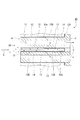
- FIG. 1 is a partially broken perspective view showing a DPF which is an embodiment of an exhaust gas purification filter of the present invention.
- 2 is a cross-sectional view showing the partition structure of the DPF in the plane indicated by the symbol ⁇ in FIG.
- the DPF 10 includes a filter base 11 made of a cylindrical porous ceramic having a large number of pores (pores), a gas flow path 12 formed in the filter base, and an exhaust upstream side end portion of the gas flow path 12. And a porous membrane 13 provided on the inner wall surface 12a of the inflow cell 12A.
- One end surface ⁇ of both end surfaces in the axial direction of the filter base 11 is an inflow surface into which the exhaust gas G containing particulate matter flows, and the other end surface ⁇ is purified by removing the particulate matter from the exhaust gas G. It is a discharge surface for discharging gas C.
- the filter base 11 is a honeycomb structure made of heat-resistant porous ceramics such as silicon carbide, cordierite, aluminum titanate, silicon nitride and the like.
- the filter base 11 is formed with a partition wall 14 extending along the axial direction, which is the flow direction of the exhaust gas G, and an axially hollow region surrounded by the partition wall 14 has a large number of cellular gas flow paths 12.
- the “honeycomb structure” in the present embodiment uses a structure in which a plurality of gas flow paths 12 are formed in the filter base 11 so as to be parallel to each other.
- the cross-sectional shape in the direction orthogonal to the axial direction of the gas flow path 12 is a square shape, but is not limited thereto, and various cross-sectional shapes such as a polygonal shape, a circular shape, and an elliptical shape can be used.
- the gas flow path 12 formed near the outer periphery of the filter base 11 has an arc shape in a part of the cross-sectional shape.
- the gas flow path 12 is arranged without a gap to the vicinity of the outer periphery of the filter base 11. Therefore, the gas flow path 12 having a cross-sectional shape following the outer shape of the filter base 11 is used.
- the average pore diameter of the partition wall 14 made of porous ceramics is preferably 5 ⁇ m or more and 50 ⁇ m. If the average pore diameter is less than 5 ⁇ m, the pressure loss due to the partition wall 14 itself is increased, which is not preferable. On the other hand, if the average pore diameter exceeds 50 ⁇ m, the strength of the partition wall 14 becomes insufficient, and it becomes difficult to form the porous film 13 on the partition wall 14, which is not preferable.
- the gas flow path 12 has a structure in which the upstream end and the downstream end are alternately closed when viewed from the flow direction (longitudinal direction) of the exhaust gas G, that is, the upstream side that is the inflow side of the exhaust gas G.
- An inflow cell 12A having an open end (inflow surface) and an outflow cell 12B in which a downstream end (discharge surface), which is the side from which the purified gas C is discharged, are opened.
- a porous film 13 containing silicon carbide is formed on the inner wall surface 12a of the inflow cell 12A (the surface of the partition wall 14 constituting the inflow cell 12A).
- the porous film 13 contains silicon carbide means that the porous film 13 is formed of particles containing at least silicon carbide, or the porous film 13 contains particles containing silicon carbide and other components. It means that it is formed from a complex with particles.
- the proportion of silicon carbide in the porous film 13 is preferably 50% by volume or more, and more preferably 80% by volume or more.
- the particles other than silicon carbide constituting the porous film 13 include at least one element selected from Group 3 to Group 14 such as silicon (Si), aluminum (Al), zirconium (Zr), and titanium (Ti). Or the particle
- the particles forming the porous film 13 are (1) particles made of silicon carbide alone, (2) silicon carbide and other components, for example, at least one element selected from Group 3 to Group 14 or their elements.
- Particles in which oxides, carbides and nitrides are compounded (3) particles made of silicon carbide alone, and at least one element selected from other components, for example, Group 3 to Group 14 or oxides thereof , Composites with particles made of carbide, nitride, (4) silicon carbide and other components, for example, at least one element selected from Group 3 to Group 14 or oxides, carbides, nitrides thereof Any of the composite particles and composites of other components, for example, at least one element selected from Group 3 to Group 14 or particles composed of oxides, carbides, and nitrides thereof. Good.
- particles made of at least one element selected from Group 3 to Group 14 such as silicon, aluminum, zirconium, and titanium, or oxides, carbides, and nitrides thereof are included as a sintering aid for silicon carbide. May be.
- the porous film 13 is formed as an independent film on the inner wall surface 12a of the inflow cell 12A without entering the pores of the porous ceramics constituting the partition wall 14 of the filter base 11. That is, the particles containing silicon carbide forming the porous film 13 are formed on the inner wall surface 12a of the inflow cell 12A so as to penetrate only to the entrance portion of the pores formed in the partition wall 14. And the porous membrane 13 has many pores, these pores communicate, and as a result, it becomes a filter-like porous which has a through-hole.
- the particulate matter 30 contained in the exhaust gas G is collected and removed by the porous film 13 provided on the inner wall surface 12a of the inflow cell 12A, and the purified gas C from which the particulate matter 30 has been removed is Then, it flows in the outflow cell 12B from the end surface ⁇ side to the end surface ⁇ side, and is discharged out of the filter from the open end (end surface ⁇ ) of the outflow cell 12B.
- the porous membrane 13 has a silicon dioxide layer on at least the outer surface (the surface facing the inflow cell 12A). With this configuration, it is possible to improve the combustion efficiency of the particulate matter 30 when the particulate matter 30 collected in the porous membrane 13 is burned to regenerate the exhaust gas purification filter 10. The reason for this is not necessarily clear, but in the regeneration process of the exhaust gas purification filter 10, the particulate matter 30 trapped in the porous film 13 acts as an oxidation point generated in the silicon dioxide layer on the surface of the porous film 13.
- a silicon dioxide layer is provided on at least the outer surface portion of the porous film
- the silicon dioxide layer is provided on the surface of the silicon carbide particles constituting the surface portion of the porous film. It is not necessary that a silicon dioxide layer is provided inside the porous film 13.
- a silicon dioxide layer is formed on the portion of the porous membrane 13 in contact with the gas inside the pores.
- the silicon dioxide layer is provided on the surface portion of the porous membrane and the portion in contact with the gas in the internal pores”, it corresponds to the silicon carbide particles constituting the surface portion of the porous membrane and the pore walls inside.
- the silicon dioxide layer is provided on the surface of the silicon carbide particles in the portion, that is, the portion that comes into contact with the gas when the gas flows in the porous membrane.
- the reason why “the silicon dioxide layer is preferably formed in the portion of the porous membrane in contact with the gas inside the pores” is a small part, but the particulate matter 30 is contained in the porous membrane. This is considered to be due to the possibility of intrusion and also effective for combustion decomposition of incomplete combustion gas contained in exhaust gas and combustion gas.
- the silicon dioxide layer in the porous film 13 is formed by sintering silicon carbide particles to form a porous film, and then heating the porous film in an oxygen-containing atmosphere or applying a silane compound to the porous film.
- the porous film 13 may be formed by a method of chemical treatment such as thermal decomposition after impregnation or adsorption, or by using silicon carbide particles having a silicon dioxide layer formed on the surface in advance.
- the thickness of the silicon dioxide layer in the porous film 13 is preferably 0.5 nm or more and 30 nm or less. More preferably, it is the range of 1 nm or more and 10 nm or less.
- the volume ratio of the silicon dioxide layer in the porous film 13 is preferably 2% by volume or more and 50% by volume or less. More preferably, it is the range of 10 volume% or more and 40 volume% or less.
- the volume of the silicon dioxide layer is less than 2% by volume, the particles constituting the porous film have a preferred average primary particle diameter of more than 0.05 ⁇ m and 3 ⁇ m or less. There is a possibility that the silicon layer cannot be formed and the effect of improving the combustion efficiency cannot be obtained.
- the proportion of the silicon dioxide layer exceeds 50% by volume, the heat resistance of the film structure in the porous film 13 may be significantly reduced.
- the average pore diameter of the porous membrane 13 is preferably larger than 0.05 ⁇ m and not larger than 3 ⁇ m. More preferably, they are 0.06 micrometer or more and 3 micrometers or less, Most desirably, they are 0.1 micrometer or more and 2.5 micrometers or less.
- the average pore diameter of the porous membrane 13 is smaller than the pore diameter of the partition wall 14 (that is, the average pore diameter of the conventional DPF: about 5 to 50 ⁇ m). For this reason, the particulate matter 30 hardly collects into the partition wall 14 and is collected with high efficiency by the porous film 13 from the stage where the accumulation amount is small.
- the average pore diameter of the porous membrane 13 is set to the above range because when the average pore diameter is 0.05 ⁇ m or less, the pressure loss increases when exhaust gas containing particulate matter flows into the exhaust gas purification filter 10. This is because if the average pore diameter of the porous membrane 13 exceeds 3 ⁇ m, the combustion efficiency of the particulate matter may not be improved when the exhaust gas purification filter 10 is regenerated.
- the average porosity of the porous membrane 13 is preferably 50% or more and 90% or less, more preferably 60% or more and 85% or less. If the average porosity of the porous membrane 13 is less than 50%, the average porosity of the porous membrane 13 is the same as or lower than the porosity of the filter substrate 11, which may cause an increase in pressure loss and may cause a cost increase. There is. On the other hand, if the average porosity of the porous membrane 13 exceeds 90%, it may be difficult to maintain the structure and strength of the porous membrane.
- the film thickness of the porous film 13 is 60 ⁇ m or less at the portion of the inner wall surface 12a that planarly overlaps the pores of the partition wall 14, and at the portion of the inner wall surface 12a that planarly overlaps the solid portion of the partition wall. It is preferable that they are 5 micrometers or more and 60 micrometers or less.
- FIG. 3 is a view schematically showing the fine structure of the cross section of the partition wall 14 and the porous membrane 13 provided on the partition wall 14, and also shows the flow (flow path) of exhaust gas and combustion gas. is there.
- FIGS. 3A and 3B show the case where the thickness of the porous film is within the range of the present embodiment shown above, and FIG.
- FIG. 3A shows the particulate matter 30 collected.
- FIG. 3B shows a state before the particulate matter 30 is collected and deposited on the porous film 13.
- 3 (c) and 3 (d) show a case where the thickness of the porous film is less than 5 ⁇ m, and FIG. 3 (c) shows a state before the particulate matter 30 is collected, FIG. 3 (d). Indicates a state in which the particulate matter 30 is collected and deposited on the porous film 13.
- the “hole portion” of the partition wall 14 refers to an opening provided by connecting the pores formed by the porous body constituting the partition wall 14 to the inner wall surface 12a.
- the H part corresponds. That is, here, not the pores inside the partition wall 14, but the pores exposed (opened) on the inner wall surface 12a, and the portion of the porous film 13 (pores and porous film 13) located on the pores.
- the thickness of the porous film 13 in the overlapping area) is a problem.
- the “solid portion” is a portion of the partition wall that is a part of the filter base 11 made of porous ceramics, excluding the void portion, and a portion where the ceramic portion is directly exposed on the inner wall surface 12a. And corresponds to the S portion in FIG.
- the film thickness of the porous membrane 13 in the solid part is more preferably 5 ⁇ m or more and 20 ⁇ m or less, further preferably 10 ⁇ m or more and 20 ⁇ m or less, and most preferably 10 ⁇ m or more and 15 ⁇ m or less.
- the film thickness of the porous film 13 in the pores is more preferably 35 ⁇ m or less.
- This preferred thickness range is due to the following reason.
- the thickness of the porous film 13 is 5 ⁇ m or more, as shown in FIG. 3A, the porous film 13 is porous in the portion where the porous film 13 overlaps the solid portion of the partition wall 14.
- the thickness of the porous film 13 is less than 5 ⁇ m, the distance from the outer surface of the porous film 13 to the inner wall surface 12a is small as shown in FIG. 3C, and the number of pores in the porous film 13 is small. Therefore, in a place where the porous film 13 overlaps with the solid part of the partition wall 14 in a plane, the outer surface of the porous film 13 and the pore part of the partition wall 14 are, for example, as indicated by X in FIG. It is difficult to form a connecting exhaust gas flow path, and pressure loss may increase. Similarly, since the number of pores in the porous film 13 is small, there is a possibility that the combustion efficiency of the particulate matter 30 cannot be improved when the regeneration process is performed by burning the particulate matter.
- the particulate matter 30 is collected only in the portion of the porous film 13 that overlaps with the pores, and the collection becomes non-uniform, the collection efficiency is quickly lowered, and the number of regeneration processes is increased. There is a fear.
- the number of pores in the porous membrane 13 is small, as shown in FIG. 3D, when the regeneration process is performed by burning the particulate matter 30, the combustion efficiency of the particulate matter 30 is improved. There is a possibility that improvement cannot be achieved.
- the thickness of the porous membrane 13 exceeds 60 ⁇ m, when the exhaust gas containing the particulate matter 30 is caused to flow into the exhaust gas purification filter 10, the pressure loss due to the provision of the porous membrane 13 increases, Since the combustion efficiency of the particulate matter 30 when performing the regeneration process is hardly improved as compared with the porous membrane 13 having a thickness of 60 ⁇ m or less, the output reduction of the engine equipped with the exhaust gas purification filter 10 of the present invention is reduced. There is a risk of inviting. For the above reasons, the optimum range of the thickness of the porous membrane 13 is set.
- the porous membrane 13 is preferably formed with a substantially flat surface such that the outer surface thereof is substantially parallel to the inner wall surface 12a. That is, the inner wall surface 12a has an uneven shape that follows the shape of the particles constituting the partition wall 14. However, the surface profile of the inner wall surface 12a is hardly reflected on the outer surface of the porous film 13, and substantially. It is preferable that the surface is flat. Furthermore, it is preferable that a plane representing the inner wall surface 12a is approximately assumed, and that the plane and the outer surface of the porous membrane 13 are substantially parallel. The fact that the surface of the porous membrane and the assumed plane representing the inner wall surface 12a are substantially parallel is referred to as “substantially parallel”.
- the portion of the porous film 13 located on the pores of the partition wall 14 has a recessed shape.
- the particulate matter 30 collected by the porous membrane 13 tends to accumulate in the concave portion, and as a result, a plug is formed at a position overlapping with the hole portion through which the exhaust gas should pass, so that pressure loss is likely to occur.
- the outer surface of the porous film 13 is formed to be substantially flat, the particulate matter 30 is collected over the entire surface of the porous film 13 and is not localized.
- the porous film 13 is preferably made of silicon carbide particles having an average primary particle diameter of 0.01 ⁇ m or more and 5 ⁇ m or less, and more preferably made of silicon carbide particles having an average primary particle diameter of 1 ⁇ m or more and 4 ⁇ m or less. .
- the reason why the porous film 13 is preferably composed of silicon carbide particles having an average primary particle diameter of 0.01 ⁇ m or more and 5 ⁇ m or less is that the average primary particle diameter of the silicon carbide particles is less than 0.01 ⁇ m, This is because the pressure loss may increase when the exhaust gas containing the exhaust gas flows into the exhaust gas purification filter 10, and on the other hand, if the average primary particle diameter of the silicon carbide particles exceeds 5 ⁇ m, the surface activity of the particles themselves is reduced. In addition, since the pore diameter of the porous membrane is increased and the specific surface area is decreased, the combustion efficiency of the particulate matter is not improved when the exhaust gas purification filter 10 is regenerated.
- the exhaust gas purification filter 10 in which the porous film 13 is provided on the inner wall surface 12a of the inflow cell 12A is illustrated, but the inner wall surface of the outflow cell 12B (the surface of the partition wall 14 constituting the outflow cell 12B). May be provided.
- the porous membrane 13 may be configured to carry a decomposition promoting catalyst for promoting the decomposition of the particulate matter 30 and the gaseous substance.
- the decomposition promoting catalyst may be supported on the outer surface of the porous membrane 13 or may be supported on the inner pore wall surface.
- the decomposition promoting catalyst may be formed in a film shape in either or both of the upper layer and the lower layer of the porous membrane 13.
- the porous film 13 may be formed using particles obtained by combining particles containing silicon carbide and particles containing a decomposition promoting catalyst.
- the combustion efficiency of the particulate matter 30 at the time of regeneration can be increased by providing the porous film 13 having the silicon dioxide layer on at least the outer surface.
- the inside of the porous film 13 is silicon carbide, the heat resistance is high, and the porous structure does not change depending on the temperature cycle, so that the porous film has high durability.
- the porous substance 13 containing silicon carbide and having a pore diameter smaller than the pores of the partition wall 14 is provided on the surface of the porous partition wall 14 of the filter base 11. While maintaining the collection efficiency of 30, it is possible to suppress an increase in pressure loss, and in particular, it is possible to suppress a rate of increase in pressure loss associated with the accumulation of particulate matter during use. Thereby, the load on the vehicle at the time of driving
- the exhaust gas purification filter of the present embodiment is a porous material containing particles containing at least silicon carbide on the surface of a partition wall constituting a gas flow path of the filter, that is, a porous support having pores having an average pore diameter of 5 to 50 ⁇ m.
- a filter can be manufactured with high productivity as compared with a method of forming a porous film by flowing a gas in which particles are dispersed into a filter base.
- the coating material for forming a porous film used in the first production method of the present invention is a dispersion containing particles containing silicon carbide and a dispersion medium.
- the silicon carbide-containing particles are silicon carbide particles alone, particles formed from a composite of silicon carbide and other components, mixed particles of silicon carbide particles and other component particles, silicon carbide It means any one of mixed particles of particles formed from a composite of other components and component particles other than silicon carbide.
- particles of silicon carbide alone (silicon carbide particles) those obtained by a silica reduction method, an atchison method, a thermal plasma method, a silica precursor firing method, or the like are used.
- at least one element selected from Group 3 to Group 14 such as silicon, aluminum, boron, zirconium, titanium, or the oxide, carbide, or nitride thereof may be selected. it can.
- the coating material for forming a porous film is prepared by dispersing the particles containing silicon carbide described above in a dispersion medium.
- This dispersing step is preferably performed by a wet method.
- a disperser used in this wet method any of an open type and a closed type can be used.
- the ball mill include a rolling mill, a vibration mill, and a planetary mill.
- the stirring mill include a tower mill, a stirring tank mill, a flow pipe mill, and a tubular mill.
- the dispersion medium water or an organic solvent is preferably used.
- organic solvent include alcohols such as methanol, ethanol, 1-propanol, 2-propanol, diacetone alcohol, furfuryl alcohol, ethylene glycol and hexylene glycol, and esters such as methyl acetate and ethyl acetate.
- Ether ether such as diethyl ether, ethylene glycol monomethyl ether (methyl cellosolve), ethylene glycol monoethyl ether (ethyl cellosolve), ethylene glycol monobutyl ether (butyl cellosolve), diethylene glycol monomethyl ether, diethylene glycol monoethyl ether, ethylene glycol monoethyl ether , Ethers such as dioxane, tetrahydrofuran, acetone, methyl ethyl ketone, acetyl
- ketones such as seton and acetoacetate, acid amides such as N, N-dimethylformamide, aromatic hydrocarbons such as toluene and xylene, and only one or two of these solvents. The above can be mixed and used.
- acrylic or methacrylic monomers such as methyl acrylate and methyl methacrylate, and epoxy monomers are preferably used.
- oligomer a urethane acrylate oligomer, an epoxy acrylate oligomer, an acrylate oligomer etc. are used suitably.
- water, alcohols, and ketones are preferable for paints.
- water and alcohols are more preferable, and water is most preferable.
- the surface modification of the particles containing silicon carbide may be performed in order to increase the affinity between the particles and the dispersion medium.
- surface modifiers include, but are not limited to, 3-aminopropyltrimethoxysilane, 3-aminopropyltriethoxysilane, cysteamine, tetramethylammonium hydroxide, aminoethanediol, and the like. Any surface modifier may be used as long as it has a functional group that adsorbs to the surface of particles containing silicon and has a terminal group having an affinity for the dispersion medium.
- the coating material for forming a porous film may appropriately contain a hydrophilic or hydrophobic polymer.
- Functionality such as a binder function can be imparted between the particles containing silicon carbide and a porous support such as a partition wall of an exhaust gas purification filter, for example, with this polymer.
- the above-described polymer and the like can be appropriately selected within the range in which the average secondary particle diameter of the particles in the coating material and the viscosity of the coating material are in desired values while being dissolved in the above-described dispersion medium.
- hydrophilic polymers include synthetic alcohols such as polyvinyl alcohol, polyvinyl pyrrolidone, polyethylene glycol, polyacrylamide, polystyrene sulfonic acid, polyvinyl pyrrolidone polyacrylate, and polyallylamine.
- the ratio of the mass of the polymer to the mass of the particles in the paint is such that the average secondary particle diameter of the particles in the paint and the viscosity of the paint are as desired.
- the range is preferably 0 or more and 1 or less, more preferably 0 or more and 0.8 or less, and still more preferably 0 or more and 0.5 or less.
- the above polymer is a component that is eventually burned out by heat treatment and does not remain in the porous membrane. Therefore, if the ratio exceeds 1, the polymer content is too high, resulting in an increase in cost. This is not preferable.
- the lower limit value of the range is zero.
- a surfactant, preservative, stabilizer, antifoaming agent, leveling agent and the like may be appropriately added. These can be appropriately selected so that the average secondary particle diameter of the particles in the paint and the viscosity of the paint are in a desired range. There are no particular restrictions on the amount of these surfactants, preservatives, stabilizers, antifoaming agents, leveling agents, etc., and the viscosity of the paint and the average secondary particle size of the particles in the paint are within the scope of the present invention. Thus, what is necessary is just to add according to the objective to add.
- particles containing silicon carbide are dispersed in a dispersion medium, and hydrophilic or hydrophobic polymers, surfactants, preservatives, stabilizers, antifoaming agents, leveling agents, etc. are added as necessary.
- hydrophilic or hydrophobic polymers, surfactants, preservatives, stabilizers, antifoaming agents, leveling agents, etc. are added as necessary.
- the above coating for forming a porous film is applied to the surface of the porous support to form a coating film containing a large amount of liquid components such as a solvent in addition to solid components such as particles.
- heat treatment is performed, and a silicon dioxide film is further formed to form a porous film.
- the above porous membrane is formed on the inner wall surface 12 a of the inflow cell 12 ⁇ / b> A (the surface of the partition wall 14 constituting the inflow cell 12 ⁇ / b> A) of the gas flow path 12, whose end on the exhaust gas upstream side is opened.
- a coating film is formed by applying a forming paint, and the resulting coating film is heat-treated, and further a silicon dioxide film is formed on at least the outer surface of the porous film by heat treatment or chemical treatment.
- the coating method may be appropriately selected according to the shape and material of the porous support, and is not particularly limited, but a normal wet coating method such as wash coating or dip coating can be used.
- a process such as removal of an excess coating liquid more than an amount necessary for obtaining a desired film thickness may be performed using compressed air or the like.
- the porous support may be in a dry state, but the porous support is immersed in a solvent in advance, and the air in the pores of the porous support is replaced with a solvent in advance. Is preferred. The reason for this is that air remaining in the pores of the porous support is released as bubbles from the porous support during or after the coating process, and the porous film is not partially formed. This is because there is an effect that a uniform porous film can be obtained.
- drying conditions depend on the type and amount of solvent used, they cannot be defined unconditionally. For example, in the case of water, it is preferably about 15 minutes to 10 hours at 50 ° C. or more and 200 ° C. or less.
- This drying step may be performed in combination with the heat treatment step described below.
- the heat treatment step may be performed by raising the temperature as it is after the drying step.
- the drying step can be substantially omitted by adjusting the temperature raising condition in the heat treatment step so that the temperature raising step in the heat treatment step is combined with the drying step.
- the coating film contains the above-described polymer, surfactant, preservative, stabilizer, antifoaming agent, leveling agent, etc. as necessary.
- Heat treatment is performed to remove and form particles having a porous structure by sintering particles containing silicon carbide in the coating film.
- the heat treatment temperature is preferably 900 ° C. or higher and 2000 ° C. or lower, more preferably 1000 ° C. or higher and 1800 ° C. or lower.
- the heat treatment time is preferably 0.5 hours or more and 10 hours or less, more preferably 1 hour or more and 4 hours or less.
- the atmosphere during the heat treatment is preferably performed in an inert atmosphere such as nitrogen, argon, neon, or xenon, or a reducing atmosphere such as hydrogen or carbon monoxide. If heat treatment is performed in an inert atmosphere or a reducing atmosphere, there is no possibility that the surface of particles containing silicon carbide or the outer surface of the porous film formed by heat treatment will be oxidized to form a silicon dioxide film.
- a silicon dioxide film having a controlled film thickness can be obtained by the process of “forming a silicon dioxide layer on the surface of the porous film”.
- the heat treatment can also be performed in an oxidizing atmosphere such as the atmosphere.
- the heat treatment (sintering) conditions for forming the porous structure and silicon dioxide It is necessary to simultaneously control the conditions for forming the layer, and it is necessary to tighten the heat treatment conditions and increase the accuracy of control. Therefore, if these two conditions can be solved at the same time, it is preferable because the process can be shortened. If not, the heat treatment (sintering) process for forming the porous structure is performed in an inert atmosphere or a reducing property.
- the step of forming the silicon dioxide layer on the atmosphere and the surface of the porous film is preferably carried out separately in an oxidizing atmosphere.
- the porous film obtained by the heat treatment is heat-treated in an oxidizing atmosphere such as an air atmosphere, or by using a chemical treatment such as thermal decomposition of a silane compound, at least the porous film.
- a silicon dioxide layer is formed on the outer surface of the membrane, that is, on the outer surface of the porous membrane and, if necessary, the surface of the portion in contact with the gas inside the porous pores.
- the preferable film thickness of the silicon dioxide layer is 0.5 nm or more and 30 nm or less.
- the heat treatment temperature in the case of heat treatment in an oxidizing atmosphere for forming the silicon dioxide layer may be equal to or higher than the temperature at which the surface of the particles containing silicon carbide forming the porous film is oxidized.
- the heat treatment time depends on the heat treatment temperature and the required thickness of the silicon dioxide layer, but is preferably 0.5 hours or more and 20 hours or less. This is because the control of the layer thickness becomes difficult when the time is less than 0.5 hours, while the controllability of the layer thickness remains the same when the time exceeds 20 hours.
- the atmosphere for the heat treatment is an oxidizing atmosphere such as air or oxygen as described above.
- the vapor of the silane compound may be adsorbed by applying a vapor of a highly volatile silane compound such as hexamethyldisilazane (HMDS) to the porous film.
- HMDS hexamethyldisilazane
- the silane compound in addition to the above hexamethyldisilazane, tetramethoxysilane, tetraethoxysilane, methylsilane, dimethylsilane, trimethylsilane, diethylsilane, propylsilane, phenylsilane, or a substituted or partial hydrolyzate thereof may be used. Can be mentioned.
- the method of forming the silicon dioxide layer by decomposing the attached silane compound is not particularly limited as long as the porous film obtained in the previous step is not deteriorated, but a method of thermally decomposing the silane compound by heat treatment is preferred. Can be used.
- the heat treatment conditions depend on the type of silane compound and the amount of adhesion, but are usually 500 ° C. to 1000 ° C., 0.5 hours to 20 hours, and may be heat-treated in an oxidizing atmosphere.
- the porous film 13 of this embodiment can be obtained by forming the silicon dioxide layer on at least the outer surface of the porous film made of particles containing silicon carbide.
- the required thickness of the silicon dioxide layer tends to increase.
- the activity of the particles themselves decreases. I guess because. The same applies to the production method II.
- first, particles containing silicon carbide are partially sintered by heat treatment in a reducing atmosphere or in an inert atmosphere to form a three-dimensional structure having pores.
- a porous film is formed, and a porous film having a solid three-dimensional structure is obtained.
- the porous film is heat-treated in an oxidizing atmosphere, or by attaching a silane compound to the porous film and thermally decomposing the silane compound, at least on the outer surface portion of the porous film without destroying the three-dimensional structure.
- a silicon dioxide layer can be formed.
- a monolith structure in which silicon carbide particles are partially sintered is formed by heat-treating a coating film made of silicon carbide particles at 1200 ° C. for 2 hours in an argon atmosphere, and then 800 ° C. in an air atmosphere. By heat-treating for 4 hours, a 1 nm thick silicon dioxide layer can be formed on the surface of the silicon carbide particles constituting the porous film. Further, for example, after a coating film made of silicon carbide particles is heat-treated in an argon atmosphere at 1200 ° C. for 2 hours to form a monolith structure in which silicon carbide particles are partially sintered, a partial hydrolyzate of tetramethoxysilane is formed. The silicon dioxide layer having a thickness of 2 nm can be formed on the surface of the silicon carbide particles by applying and heat-treating in an air atmosphere at 600 ° C. for 10 hours.
- the coating material for forming a porous film used in the production method II of the present invention is a dispersion liquid containing silicon carbide and particles having a silicon dioxide layer on the surface and a dispersion medium.
- the particles containing silicon carbide and having a silicon dioxide layer on the surface are silicon carbide particles alone, particles formed from a composite of silicon carbide and other components, silicon carbide particles and other components Any one of a mixed particle of particles and a mixed particle of particles formed of a composite of silicon carbide and other components and component particles other than silicon carbide, wherein silicon carbide is included in the particles.
- the thickness of the silicon dioxide layer is preferably 0.5 nm or more and 30 nm or less, more preferably 1 nm or more and 10 nm or less.
- the volume ratio of the silicon dioxide layer to the whole particle is preferably 2% by volume or more and 50% by volume or less, more preferably 10% by volume or more and 40% by volume or less. When outside this range, the thickness of the silicon dioxide layer and the volume ratio of the silicon dioxide layer in the porous film 13 formed using particles containing this silicon carbide and having a silicon dioxide layer on the surface are within a predetermined range. May not fit.
- silicon carbide particles those obtained by a silica reduction method, an atchison method, a thermal plasma method, a silica precursor firing method, or the like are used as in the first production method.
- a component other than silicon carbide at least one element selected from Group 3 to Group 14 such as silicon, aluminum, boron, zirconium, titanium, or the oxide, carbide, or nitride thereof may be selected. it can.
- the silicon dioxide layer formed in advance on the particle surface has an effect such as a sintering aid, it is not always necessary to add components other than silicon carbide.
- the method of forming the silicon dioxide layer on the surface of the particles containing silicon carbide as a component there is no particular limitation on the method of forming the silicon dioxide layer on the surface of the particles containing silicon carbide as a component, but a method of performing heat treatment in an oxidizing atmosphere such as air can be suitably used.
- the heat treatment temperature is preferably 600 ° C. or more and 1000 ° C. or less, and the heat treatment time is preferably 0.5 hour or more and 20 hours or less.
- a silane compound may be attached in advance to the surface of particles containing silicon carbide as a component, and a silicon dioxide layer may be formed from the silane compound by chemical treatment such as thermal decomposition.
- the porous film-forming paint is prepared by dispersing the particles containing silicon carbide described above in a dispersion medium. Since the method of forming the paint is the same as that of the first manufacturing method, details are omitted.
- the above coating for forming a porous film is applied to the surface of the porous support to form a coating film containing a large amount of liquid components such as a solvent in addition to solid components such as particles.
- heat treatment is performed to form a porous film.
- the above porous membrane is formed on the inner wall surface 12 a of the inflow cell 12 ⁇ / b> A (the surface of the partition wall 14 constituting the inflow cell 12 ⁇ / b> A) of the gas flow path 12, whose end on the exhaust gas upstream side is opened.
- the forming film is applied to form a coating film, and the obtained coating film is heat-treated to form the porous film 13.
- the method for forming the coating film and the drying method are the same as those in the first manufacturing method, and thus the details are omitted. Further, in the heat treatment method, since the silicon dioxide layer is already formed on the particle surface, it is performed in an inert atmosphere or a reducing atmosphere, and not in an oxidizing atmosphere. Except for this point, the manufacturing method is the same as that of the first manufacturing method, and the details are omitted.
- particles containing at least silicon carbide are heat-treated in an oxidizing atmosphere, or by thermally decomposing a silane compound attached to the particle surface, at least silicon carbide and the surface are included.
- particles having a silicon dioxide layer are heat-treated in a reducing atmosphere or in an inert atmosphere to partially sinter the particles containing silicon carbide and having a silicon dioxide layer on the surface, thereby providing three-dimensional pores.
- exhaust gas purification filter samples of Examples 1 to 7 and Comparative Examples 1 and 2 were prepared. Then, each sample was evaluated using the evaluation method shown below.
- Example 1 100 parts by mass of silicon carbide powder particles having an average particle diameter of 0.03 ⁇ m and 2 parts by mass of alumina powder particles having an average particle diameter of 0.2 ⁇ m as a sintering aid are mixed, and silicon carbide particles and alumina powder are mixed. Ceramic powder particles (SiC—Al 2 O 3 ) composed of particles were obtained. Next, the ceramic particles are first put in pure water so that the content of the ceramic particles is 12% by volume, the content of water is 87% by volume, and the content of the gelling agent is 1% by volume. This was put into a stirrer and mixed with a ball mill at a rotation speed of 60 rpm for 12 hours to obtain a slurry. Thereafter, gelatin was added as a gelling agent to this slurry and mixed for 15 minutes to obtain a porous film-forming paint according to Example 1.
- a ceramic honeycomb structure (filter substrate (silicon carbide honeycomb filter: DPF, average pore diameter in partition walls: 12 ⁇ m, average porosity is 45%)) is dipped in a paint for forming a porous film and then pulled up to 100 ° C. And dried for 12 hours. Thereafter, the ceramic honeycomb structure coated with the ceramic powder particles was placed in an atmosphere furnace, the atmosphere in the furnace was changed to an argon atmosphere, and the furnace temperature was raised to 1000 ° C. at a rate of 15 ° C. per minute. And sintering for 1 hour to form a porous film formed by sintering ceramic powder particles on the surface of the ceramic honeycomb structure. Thereafter, heat treatment was performed at 800 ° C.
- filter substrate silicon carbide honeycomb filter: DPF, average pore diameter in partition walls: 12 ⁇ m, average porosity is 45%
- the manufactured exhaust gas purification filter had an average pore diameter of the porous membrane of 0.08 ⁇ m.
- the formed porous membrane has an average thickness up to the particle surface of the ceramic honeycomb structure (thickness on the solid part having no pores) of 10 ⁇ m, and the thickness up to the pore part (pores are small). The thickness on the hole portion opened on the surface) was 18 ⁇ m on average.
- a silicon dioxide layer having a thickness of 2.0 nm was formed on the outermost surface of the porous film.
- the average porosity of the porous membrane was 85%.
- Example 2 Silicon carbide powder particles having an average particle diameter of 0.9 ⁇ m are used as ceramic powder particles (SiC) as a constituent material of the porous film.
- the content of the ceramic powder particles is 6% by volume and the water content is 91.
- the ceramic powder particles are put into pure water so that the content of the volume% and the gelling agent is 3% by volume.
- the ceramic powder is put into a stirrer and mixed in a ball mill at a rotation speed of 60 rpm for 12 hours. A slurry was obtained. Thereafter, gelatin was added as a gelling agent to the slurry and mixed for 15 minutes to obtain a porous film-forming paint according to Example 2.
- a ceramic honeycomb structure (silicon carbide honeycomb filter: DPF, average pore diameter of 12 ⁇ m in partition walls, average porosity of 45%) is dipped in this paint for forming a porous film, then pulled up, and heated at 100 ° C. for 12 hours. Dried. Thereafter, the ceramic honeycomb structure coated with the ceramic particles was placed in an atmosphere furnace, the furnace atmosphere was changed to an argon atmosphere, and the furnace temperature was raised to 1800 ° C. at a rate of 15 ° C. per minute. Was held for 2 hours for sintering, and a porous film formed by sintering ceramic powder particles was formed on the surface of the ceramic honeycomb structure. Thereafter, heat treatment was performed at 900 ° C.
- the manufactured exhaust gas purification filter had an average pore diameter of the porous membrane of 1.1 ⁇ m.
- the formed porous film had an average thickness of 11 ⁇ m on the solid portion of the ceramic honeycomb structure and an average thickness of 20 ⁇ m on the pores.
- a silicon dioxide layer having a thickness of 1.5 nm was formed on the outermost surface of the porous film.
- the average porosity of the porous membrane was 81%.
- Example 3 100 parts by mass of silicon carbide powder granules having an average particle diameter of 1.2 ⁇ m and 2 parts by mass of yttria powder granules having an average particle diameter of 0.1 ⁇ m as a sintering aid are mixed to obtain silicon carbide powder and yttria powder. Ceramic powder particles (SiC—Y 2 O 3 ) composed of particles were obtained. Next, first, the ceramic particles are adjusted so that the content of the ceramic particles is 6.5% by volume, the content of water is 92.5% by volume, and the content of the gelling agent is 1% by volume.
- a ceramic honeycomb structure (silicon carbide honeycomb filter: DPF, average pore diameter of 12 ⁇ m in partition walls, average porosity of 45%) is dipped in the paint for forming a porous film, then pulled up and dried at 100 ° C. for 12 hours. I let you. Thereafter, the ceramic honeycomb structure coated with the ceramic powder particles was placed in an atmosphere furnace, the furnace atmosphere was changed to an argon atmosphere, and the furnace temperature was raised to 1700 ° C. at a rate of 15 ° C. per minute. Was held for 2 hours for sintering, and a porous film formed by sintering ceramic powder particles was formed on the surface of the ceramic honeycomb structure. Thereafter, heat treatment was performed at 850 ° C.
- DPF silicon carbide honeycomb filter
- the manufactured exhaust gas purification filter had an average pore diameter of the porous membrane of 1.6 ⁇ m.
- the formed porous membrane had an average thickness of 10 ⁇ m on the solid portion of the ceramic honeycomb structure and an average thickness of 15 ⁇ m on the pores.
- a silicon dioxide layer having a thickness of 2.0 nm was formed on the outermost surface of the porous film.
- the average porosity of the porous membrane was 76%.
- Example 4" 100 parts by mass of silicon carbide powder granules having an average particle diameter of 2.0 ⁇ m and 2 parts by mass of yttria powder granules having an average particle diameter of 0.1 ⁇ m as a sintering aid are mixed to obtain silicon carbide powder and yttria powder.
- Ceramic powder particles SiC—Y 2 O 3 ) composed of particles were obtained.
- the ceramic particles are first put in pure water so that the content of the ceramic particles is 8% by volume, the content of water is 90% by volume, and the content of the gelling agent is 2% by volume. This was put into a stirrer and mixed for 3 hours at a rotational speed of 60 rpm in a ball mill to obtain a slurry. Thereafter, gelatin was added as a gelling agent to this slurry and mixed for 15 minutes to obtain a coating material for forming a porous film according to Example 4.
- a ceramic honeycomb structure (silicon carbide honeycomb filter: DPF, average pore diameter of 12 ⁇ m in partition walls, average porosity of 45%) is dipped in the paint for forming a porous film, then pulled up and dried at 100 ° C. for 12 hours. I let you. Thereafter, the ceramic honeycomb structure coated with the ceramic particles is placed in an atmosphere furnace, the furnace atmosphere is set to an argon atmosphere, and the furnace temperature is increased to 1700 ° C. at a rate of 15 ° C. per minute. Sintering was carried out for 2 hours to form a porous film formed by sintering ceramic powder particles on the surface of the ceramic honeycomb structure. Thereafter, heat treatment was performed at 800 ° C.
- an exhaust gas purification filter having a porous membrane having a silicon dioxide layer on the surface was produced.
- the average pore diameter of the porous membrane was 2.0 ⁇ m.
- the formed porous film had an average thickness of 21 ⁇ m on the solid portion of the ceramic honeycomb structure and an average thickness of 35 ⁇ m on the pores.
- a 0.6 nm thick silicon dioxide layer was formed on the outermost surface of the porous film.
- the average porosity of the porous membrane was 63%.
- Example 5 100 parts by mass of silicon carbide powder particles having an average particle diameter of 5.0 ⁇ m and 1 part by mass of boron carbide powder particles having an average particle diameter of 0.8 ⁇ m as a sintering aid are mixed to obtain silicon carbide particles and boron Ceramic powder particles (SiC-B 4 C) made of carbide powder particles were obtained.
- the ceramic particles are first put in pure water so that the content of the ceramic particles is 12% by volume, the content of water is 87% by volume, and the content of the gelling agent is 1% by volume. This was put into a stirrer and mixed for 6 hours at a rotation speed of 60 rpm in a ball mill to obtain a slurry. Thereafter, gelatin was added as a gelling agent to the slurry and mixed for 15 minutes to obtain a porous film-forming paint according to Example 5.
- a ceramic honeycomb structure (silicon carbide honeycomb filter: DPF, average pore diameter of 12 ⁇ m in partition walls, average porosity of 45%) is dipped in the paint for forming a porous film, then pulled up and dried at 100 ° C. for 12 hours. I let you. Thereafter, the ceramic honeycomb structure coated with the ceramic particles is placed in an atmosphere furnace, the furnace atmosphere is set to an argon atmosphere, and the furnace temperature is increased to 2000 ° C. at a rate of 15 ° C. per minute. Sintering was carried out for 2 hours to form a porous film formed by sintering ceramic powder particles on the surface of the ceramic honeycomb structure. Thereafter, heat treatment was performed at 850 ° C.
- DPF silicon carbide honeycomb filter
- an exhaust gas purification filter having a porous membrane having a silicon dioxide layer on the surface was produced.
- the average pore diameter of the porous membrane was 3.0 ⁇ m.
- the formed porous film had an average thickness of 5 ⁇ m on the solid portion of the ceramic honeycomb structure and an average thickness of 11 ⁇ m on the pores.
- a 12 nm thick silicon dioxide layer was formed on the outermost surface of the porous film.
- the average porosity of the porous membrane was 51%.
- Example 6 100 parts by mass of silicon carbide powder granules having an average particle diameter of 0.6 ⁇ m and 2 parts by mass of alumina powder granules having an average particle diameter of 0.2 ⁇ m as a sintering aid are mixed to obtain silicon carbide powder and alumina powder Ceramic powder particles (SiC—Al 2 O 3 ) composed of particles were obtained.
- the ceramic particles are first put in pure water so that the content of the ceramic particles is 12% by volume, the content of water is 87% by volume, and the content of the gelling agent is 1% by volume. This was put into a stirrer and mixed with a ball mill at a rotation speed of 60 rpm for 12 hours to obtain a slurry. Thereafter, gelatin was added as a gelling agent to the slurry and mixed for 15 minutes to obtain a porous film-forming paint according to Example 6.
- a ceramic honeycomb structure (silicon carbide honeycomb filter: DPF, average pore diameter of 12 ⁇ m in partition walls, average porosity of 45%) is dipped in the paint for forming a porous film, then pulled up and dried at 100 ° C. for 12 hours. I let you. Thereafter, the ceramic honeycomb structure coated with the ceramic particles is placed in an atmosphere furnace, the furnace atmosphere is set to an argon atmosphere, and the furnace temperature is increased to 1700 ° C. at a rate of 15 ° C. per minute. Sintering was carried out for 2 hours to form a porous film formed by sintering ceramic powder particles on the surface of the ceramic honeycomb structure.
- DPF silicon carbide honeycomb filter
- the ceramic honeycomb structure on which the porous film thus obtained was formed was dipped in a 0.01% SiO 2 solid content coating solution obtained by partially hydrolyzing tetramethoxysilane and then pulled up, and 100 ° C. in an air atmosphere. And dried for 5 hours. Thereafter, the ceramic honeycomb structure was put in an electric furnace and heat-treated at 600 ° C. for 60 hours in an air atmosphere to manufacture an exhaust gas purification filter having a porous film having a silicon dioxide layer on the surface.
- the average pore diameter of the porous membrane was 0.9 ⁇ m.
- the formed porous film had an average thickness of 19 ⁇ m on the solid portion of the ceramic honeycomb structure and an average thickness of 40 ⁇ m on the pores.
- a 27.0 nm thick silicon dioxide layer was formed on the outermost surface of the porous film.
- the average porosity of the porous membrane was 70%.
- Example 7 Except that the condition for forming the silicon dioxide layer on the surface of the porous film was a heat treatment at 500 ° C. for 2 hours in an air atmosphere, the same method as in Example 6 was used. An exhaust gas purification filter provided with a porous membrane having a layer was produced. In the manufactured exhaust gas purification filter, the average pore diameter of the porous membrane was 0.9 ⁇ m. The formed porous film had an average thickness of 18 ⁇ m on the solid portion of the ceramic honeycomb structure and an average thickness of 41 ⁇ m on the pores. In addition, a 23.0 nm thick silicon dioxide layer was formed on the outermost surface of the porous film. The average porosity of the porous membrane was 71%.
- Example 8 100 parts by mass of silicon carbide powder granules having a mean particle size of 0.03 ⁇ m and heat treated at 800 ° C. for 2 hours in an air atmosphere to form a 3 nm silicon dioxide layer on the surface, and as a sintering aid Were mixed with 2 parts by mass of alumina particles having an average particle size of 0.2 ⁇ m to obtain ceramic particles ((SiC + SiO 2 ) -Al 2 O 3 ) composed of silicon carbide particles and alumina particles. . Next, the ceramic particles are first put in pure water so that the content of the ceramic particles is 12% by volume, the content of water is 87% by volume, and the content of the gelling agent is 1% by volume.
- a ceramic honeycomb structure (silicon carbide honeycomb filter: DPF, average pore diameter of 12 ⁇ m in partition walls, average porosity of 45%) is dipped in the paint for forming a porous film, then pulled up and dried at 100 ° C. for 12 hours. I let you. Thereafter, the ceramic honeycomb structure coated with the ceramic particles is placed in an atmosphere furnace, the furnace atmosphere is set to an argon atmosphere, and the furnace temperature is increased to 1700 ° C. at a rate of 15 ° C. per minute.
- DPF silicon carbide honeycomb filter: DPF, average pore diameter of 12 ⁇ m in partition walls, average porosity of 45%
- Exhaust gas purification filter comprising a porous film formed by holding a ceramic membrane for 2 hours, sintering the ceramic powder particles on the surface of the ceramic honeycomb structure, and having a porous film having a silicon dioxide layer on the surface Manufactured.
- the average pore diameter of the porous membrane was 0.9 ⁇ m.
- the formed porous film had an average thickness of 20 ⁇ m on the solid portion of the ceramic honeycomb structure and an average thickness of 42 ⁇ m on the pores.
- a silicon dioxide layer having a thickness of 3.0 nm was formed on the outermost surface of the porous film.
- the average porosity of the porous membrane was 81%.
- Ceramic powder particles (SiO 2 ) made of silicon dioxide powder particles having an average particle diameter of 0.03 ⁇ m were prepared. Next, the ceramic particles are first put in pure water so that the content of the ceramic particles is 12% by volume, the content of water is 87% by volume, and the content of the gelling agent is 1% by volume. This was put into a stirrer and mixed with a ball mill at a rotation speed of 60 rpm for 12 hours to obtain a slurry. Thereafter, gelatin was added as a gelling agent to this slurry and mixed for 15 minutes to obtain a porous film-forming paint according to Comparative Example 1.
- a ceramic honeycomb structure (silicon carbide honeycomb filter: DPF, average pore diameter of 12 ⁇ m in partition walls, average porosity of 45%) is dipped in the paint for forming a porous film, then pulled up and dried at 100 ° C. for 12 hours. I let you. Then, the exhaust gas purification filter provided with the porous membrane which consists of silicon dioxide particles was manufactured by heat-treating the ceramic honeycomb structure coated with the ceramic powder particles at 800 ° C. for 6 hours in the air atmosphere. The manufactured exhaust gas purification filter had an average pore diameter of the porous membrane of 0.14 ⁇ m. The formed porous film had an average thickness of 12 ⁇ m on the solid portion of the ceramic honeycomb structure and an average thickness of 43 ⁇ m on the pores. The average porosity of the porous membrane was 86%.
- Comparative Example 2 100 parts by mass of silicon carbide powder particles having an average particle diameter of 0.1 ⁇ m and 1 part by mass of boron carbide powder particles having an average particle diameter of 0.8 ⁇ m as a sintering aid are mixed to obtain silicon carbide particles and boron A ceramic powder (SiC-B 4 C) composed of carbide powder was obtained. Next, first, the ceramic powder particles are adjusted so that the content of the ceramic powder particles is 8.0% by volume, the content of water is 91.0% by volume, and the content of the gelling agent is 1% by volume. It was put in pure water, put in a stirrer, and mixed at a rotation speed of 60 rpm for 12 hours in a ball mill to obtain a slurry. Thereafter, gelatin was added as a gelling agent to this slurry and mixed for 15 minutes to obtain a porous film-forming paint according to Comparative Example 2.
- a ceramic honeycomb structure (silicon carbide honeycomb filter: DPF, average pore diameter of 12 ⁇ m in partition walls, average porosity of 45%) is immersed in the coating material for forming a porous film for 3 minutes, and then pulled up, and then heated at 100 ° C. for 12 Let dry for hours. Thereafter, the ceramic honeycomb structure coated with the ceramic particles is placed in an atmosphere furnace, the furnace atmosphere is set to an argon atmosphere, and the furnace temperature is increased to 2000 ° C. at a rate of 15 ° C. per minute. Sintering was performed for 30 minutes, and a porous film formed by sintering ceramic powder particles was formed on the surface of the ceramic honeycomb structure.
- DPF silicon carbide honeycomb filter
- the average pore diameter of the porous membrane was 0.3 ⁇ m.
- the formed porous film had an average thickness of 24 ⁇ m on the solid portion of the ceramic honeycomb structure and an average thickness of 50 ⁇ m on the pores. Note that no silicon dioxide layer was formed on the surface of the porous film.
- the average porosity of the porous membrane was 80%.
- Table 1 shows the evaluation results of the obtained exhaust gas purification filter samples for the above Examples and Comparative Examples.
- Examples 1 to 5 Good results were obtained when the layer was formed (Examples 1 to 5) as compared with the case where the silicon dioxide layer was formed by the liquid phase method (Examples 6 and 7). Furthermore, among the examples, those in which the thickness of the silicon dioxide layer was set to 1 nm or more and 10 nm or less (Examples 1 to 3, 8), the results of the combustion test were good.
- the exhaust gas purification filter of the present invention it is possible to suppress an increase in pressure loss while maintaining the collection efficiency of particulate matter.
- the present invention is extremely useful in the industry because the interval between filter regeneration cycles can be increased and the number of regenerations can be reduced.
Abstract
Description
本願は、2009年9月30日に、日本に出願された特願2009-228767号に基づき優先権を主張し、その内容をここに援用する。
一般に、自動車用ディーゼルエンジンでは、粒子状物質を捕集するための排ガス浄化フィルタとして、セラミックス製の目封じタイプのハニカム構造体(フィルタ基体)を有するDPF(Diesel Particulate Filter)が使用されている。このハニカム構造体は、セラミックス製のハニカム構造体のセル(ガス流路)の両端を市松模様に目封じしたものであり、このセル間の隔壁中の細孔を排ガスが通過する際、粒子状物質が捕集される(例えば特許文献1、2)。
また粒子状物質が層状に堆積することにより圧力損失が上昇するため、自動車の走行に負荷が生じる。このため、定期的に何らかの方法で粒子状物質を除去し、ハニカム構造体を再生する必要がある。
そこで、従来、粒子状物質を除去するため、燃料を噴射し排気ガス温度を上昇させることでセラミックスハニカム構造体の温度を上昇させ、堆積した粒子状物質を燃焼させることにより再生している。しかしながら、この再生方法は、燃焼の際に600℃から700℃の高温となりさらに初期にはこの温度より高くなる。このため、燃焼により生じる熱応力によってセラミックスハニカム構造体の隔壁の強度が維持できずに破損に至る場合がある。このような隔壁の破損を防止するためには熱応力のかかる時間を短くする必要があり、これには、粒子状物質の堆積量を少なくすることで、燃焼時間を極力短くすることで対処するほかない。このことから、粒子状物質の燃焼・再生サイクルの頻度は多くなり、燃焼のために使われる燃料も多くなることで燃費に悪影響を及ぼす。現在では、セラミックスハニカム構造体の性能を100%使いきってはいない。
これにより、再生時における粒子状物質の燃焼効率を高めることができる。これは、排ガス浄化フィルタの再生工程において、捕集されている粒子状物質が、多孔質膜表面の二酸化珪素層に発生した酸化点の作用と、粒子状物質と多孔質膜との接触面において熱引けが起らない環境に保持されることとによって分解され易くなるからであると推測される。
さらに本発明の排ガス浄化フィルタでは、多孔質膜の表面以外は炭化珪素であるため、耐熱性が高く、温度サイクルによっても多孔質の構造が変化せず、耐久性の高い多孔質膜を備えたものとなる。
本発明の排ガス浄化フィルタの最良の形態について説明する。ここでは、自動車用ディーゼルエンジンに用いられる排ガス浄化フィルタであるDPFを例にとり説明する。
なお、この形態は、発明の趣旨をより良く理解させるために具体的に説明するものであって、特に指定のない限り、本発明を限定するものではない。
DPF10は、多数の細孔(気孔)を有する円柱状の多孔質セラミックスからなるフィルタ基体11と、このフィルタ基体内に形成されたガス流路12と、ガス流路12のうち排気上流側端部が開放された流入セル12Aの内壁面12aに設けられた多孔質膜13と、を備えている。
フィルタ基体11の軸方向の両端面のうち一方の端面αが、粒子状物質を含む排ガスGが流入する流入面であり、他方の端面γが、上記の排ガスGから粒子状物質を取り除いた浄化ガスCを排出する排出面である。
ここで、本実施形態における「ハニカム構造」とは、フィルタ基体11に複数のガス流路12を互いに平行となるように形成した構造を用いている。ガス流路12の軸方向に直交する方向の断面形状は四角形状であるが、これに限らず、多角形、円形、楕円形などの種々の断面形状とすることができる。また、フィルタ基体11の外周付近に形成されたガス流路12は、断面形状の一部が円弧状となっているが、これはフィルタ基体11の外周付近まで隙間無くガス流路12を配置するために、フィルタ基体11の外形状に倣う断面形状のガス流路12としたものである。
多孔質膜13を構成する炭化珪素以外の粒子としては、珪素(Si)、アルミニウム(Al)、ジルコニウム(Zr)、チタン(Ti)等の3族~14族から選ばれた少なくとも1種類の元素又はそれらの酸化物、炭化物、窒化物からなる粒子を、単独又は炭化珪素に複合化させて含有させることができる。また、ホウ素(B)とその酸化物、炭化物、窒化物からなる粒子を、単独又は炭化ケイ素に複合化させて含有させてもよい。
すなわち、多孔質膜13を形成する粒子は、(1)炭化珪素単体からなる粒子、(2)炭化珪素と他の成分、例えば3族~14族から選ばれた少なくとも1種類の元素又はそれらの酸化物、炭化物、窒化物とが複合化された粒子、(3)炭化珪素単体からなる粒子と、他の成分、例えば3族~14族から選ばれた少なくとも1種類の元素又はそれらの酸化物、炭化物、窒化物からなる粒子との複合体、(4)炭化珪素と他の成分、例えば3族~14族から選ばれた少なくとも1種類の元素又はそれらの酸化物、炭化物、窒化物とが複合化された粒子と、他の成分、例えば3族~14族から選ばれた少なくとも1種類の元素又はそれらの酸化物、炭化物、窒化物からなる粒子との複合体、のいずれであってもよい。
なお、珪素、アルミニウム、ジルコニウム、チタン等の3族~14族から選ばれた少なくとも1種類の元素又はそれらの酸化物、炭化物、窒化物からなる粒子は、炭化珪素の焼結助剤として含有させてもよい。
本実施形態において、多孔質膜13は、その少なくとも外表面(流入セル12A内に臨む表面)部分に二酸化珪素層を有している。この構成により、多孔質膜13に捕集された粒子状物質30を燃焼させて排ガス浄化フィルタ10を再生させる際の粒子状物質30の燃焼効率を向上させることができる。この理由は必ずしも明確ではないが、排ガス浄化フィルタ10の再生工程において、多孔質膜13に捕集されている粒子状物質30が、多孔質膜13表面の二酸化珪素層に発生した酸化点の作用と、粒子状物質と多孔質膜接触面において熱引けが起らない環境に保持されることとによって燃焼分解され易くなるためと考えられる。さらに、本実施形態においては、気孔径を後述のように制御することなどにより、粒子状物質30のほぼすべてが深層ろ過ではなく表層ろ過で捕集される。ここで、深層ろ過捕集された粒子状物質30は、燃焼ガスの供給が不均一になることや多孔質膜との接触状態のばらつきから、急激な燃焼(異常燃焼)を起こしやすいが、本実施形態においては深層ろ過捕集された粒子状物質30がないため、急激な燃焼を防止出来ると考えられる。これらの結果、熱暴走性の悪化を招くことなく捕集した粒子状物質の燃焼性を向上できるものと推測される。
しかしながら、本実施形態においては、多孔質膜13の外表面部分に加えて、多孔質膜13の気孔内部のガスと接する部分に二酸化珪素層が形成されていることが好ましい。この、「多孔質膜の表面部分及び内部気孔中のガスと接する部分に、二酸化珪素層が設けられている」構成では、多孔質膜の表面部分を構成する炭化珪素粒子及び内部の気孔壁にあたる部分、つまり多孔質膜内をガスが流れていく際にガスと接触する部分の炭化珪素粒子表面に二酸化珪素層が設けられていればよい。このように、「多孔質膜の気孔内部のガスと接する部分に二酸化珪素層が形成されていることが好ましい」理由としては、ごく一部ではあるが、粒子状物質30が多孔質膜内部に入り込む可能性があること、さらには、排気ガスや燃焼ガス中に含まれる不完全燃焼ガスの燃焼分解に対しても効果があるためと考えられる。
多孔質膜13における二酸化珪素層の厚さは、0.5nm以上かつ30nm以下が好ましい。より好ましくは、1nm以上かつ10nm以下の範囲である。二酸化珪素層の厚さが0.5nm未満では、粒子状物質30の燃焼効率を向上させる効果が得られなくなる虞がある。二酸化珪素層の厚さが30nmを超えると、二酸化珪素層の形成に多くの時間を要する一方で、得られる効果はほとんど変わらなくなる。
多孔質膜13における二酸化珪素層の体積比は、2体積%以上かつ50体積%以下が好ましい。より好ましくは10体積%以上かつ40体積%以下の範囲である。二酸化珪素層の体積が2体積%未満では、多孔質膜を構成する粒子が好ましい平均一次粒子径を有する範囲である0.05μmより大きく3μm以下において、好ましい膜厚0.5nm以上30nm以下の二酸化珪素層を形成することができず、燃焼効率を向上させる効果が得られなくなる虞がある。一方、二酸化珪素層の割合が50体積%を超えると、多孔質膜13において膜構造の耐熱性が著しく低下する虞がある。
このように多孔質膜13の平均気孔径は、隔壁14の気孔径(すなわち従来のDPFの平均気孔径:5~50μm程度)より小さい。このため、粒子状物質30は、隔壁14にほとんど入り込むことなく、その堆積量が少ない段階から多孔質膜13により高効率に捕集される。
多孔質膜13の平均気孔径が上記範囲とされるのは、平均気孔径が0.05μm以下では、粒子状物質を含む排ガスを排ガス浄化フィルタ10内に流入させた場合に圧力損失が大きくなるからであり、多孔質膜13の平均気孔径が3μmを超えると、排ガス浄化フィルタ10の再生処理を行う場合に粒子状物質の燃焼効率の向上が見られない虞があるからである。
多孔質膜13の平均気孔率が50%未満では、多孔質膜13の平均気孔率がフィルタ基体11の気孔率と同じか低くなるため、圧力損失の上昇を招き、またコスト増加要因となる虞がある。一方、多孔質膜13の平均気孔率が90%を超えると、多孔質膜の構造や強度を維持することが困難となる虞がある。
図3は、隔壁14および隔壁14上に設けられた多孔質膜13の断面の微細構造を模式的に示した図であり、排ガスおよび燃焼ガスの流れ(流路)も併せて示した図である。ここで、図3(a)(b)は、多孔質膜の膜厚が上記に示す本実施形態の範囲内である場合であって、図3(a)は粒子状物質30が捕集される前の状態、図3(b)は多孔質膜13上に粒子状物質30が捕集堆積した状態を示している。また、図3(c)(d)は多孔質膜の膜厚が5μm未満の場合であって、図3(c)は粒子状物質30が捕集される前の状態、図3(d)は多孔質膜13上に粒子状物質30が捕集堆積した状態を示している。
固体部における多孔質膜13の膜厚は、5μm以上かつ20μm以下であることがより好ましく、さらに好ましくは10μm以上かつ20μm以下、最も好ましくは10μm以上かつ15μm以下である。また、空孔部における多孔質膜13の膜厚は、35μm以下であることがより好ましい。
まず、排ガス浄化フィルタ10において、粒子状物質30を捕集する際には、排ガスは、流入セル12A側から隔壁14の空孔部に侵入し、流出セル12B側へ通過する。そのため、多孔質膜13において、隔壁14の空孔部と重なる部分では、多孔質膜13の外表面と隔壁14の空孔部とをつなぐ排ガスの流路、例えば図3(a)のFが形成されることとなる。
ここで、多孔質膜13の厚さが5μm以上であると、図3(a)に示すように、多孔質膜13が隔壁14の固体部と重なる箇所において、多孔質膜13中に、多孔質膜13の外表面と隔壁14の空孔部とを接続するための流路を形成するのに十分な量の細孔が存在することとなる。したがって、隔壁14の固体部と平面的に重なる箇所においても、多孔質膜13の外表面と隔壁14の空孔部とをつなぐ排ガスの流路、例えば図3(a)のPが形成される。この流路が形成されることにより、圧力損失が低減され、また、粒子状物質30は多孔質膜13上に均一に捕集される。
さらに、粒子状物質30を燃焼させることによりフィルタの再生処理を行う場合においても、図3(b)のF’,P’に示すような燃焼ガスの流路が同様に形成されることから、燃焼ガスは粒子状物質30内を均一に流れることができるので、燃焼効率の向上を図ることができる。
また、同様に多孔質膜13中の細孔数が少ないため、図3(d)に示すように、粒子状物質30を燃焼させることにより再生処理を行う場合、粒子状物質30の燃焼効率の向上が図れない虞がある。
さらに、多孔質膜13の厚さが60μmを超えると、粒子状物質30を含む排ガスを排ガス浄化フィルタ10に流入させた場合に、多孔質膜13を設けることによる圧力損失も大きくなる一方で、再生処理を行う場合の粒子状物質30の燃焼効率は、多孔質膜13の厚みが60μm以下のものに比べてほとんど向上しないことから、本発明の排ガス浄化フィルタ10を取り付けたエンジンの出力低下を招く虞がある。
以上のような理由により、多孔質膜13の厚さの最適な範囲が設定される。
例えば、多孔質膜13の外表面形状が内壁面12aに倣う形状であると、隔壁14の空孔部上に位置する部分の多孔質膜13は凹んだ形状となる。そうすると、多孔質膜13で捕集される粒子状物質30が当該凹部に溜まりやすく、結果、排ガスが通過すべき空孔部と重なる位置で塞栓を形成するため、圧力損失が生じやすい。これに対して多孔質膜13の外表面がほぼ平坦に形成されていると、多孔質膜13の全面で粒子状物質30が捕集され、局在化しないので、圧力損失が生じにくくなる。
多孔質膜13が、平均一次粒子径が0.01μm以上かつ5μm以下の炭化珪素粒子からなることが好ましい理由は、炭化珪素粒子の平均一次粒子径が0.01μm未満では、粒子状物質30を含む排ガスを排ガス浄化フィルタ10内に流入した場合に圧力損失が大きくなる虞があるからであり、一方、炭化珪素粒子の平均一次粒子径が5μmを超えると、粒子自体の表面活性が低下することや、多孔質膜の気孔径が大きくなり比表面積が小さくなるため、排ガス浄化フィルタ10の再生処理を行う場合、粒子状物質の燃焼効率の向上が見られないからである。
また、多孔質膜13としては、粒子状物質30やガス状物質の分解を促進する分解促進触媒が担持された構成としてもよい。分解促進触媒は多孔質膜13の外表面に担持されていてもよく、内部の気孔壁面に担持されていてもよい。あるいは、分解促進触媒は、多孔質膜13の上層及び下層のいずれか又は両方に膜状に形成されていてもよい。また、炭化珪素を含む粒子と分解促進触媒を含む粒子とを複合化した粒子を用いて多孔質膜13を形成してもよい。
次に、本発明の排ガス浄化フィルタの製造方法について説明する。
本実施形態の排ガス浄化フィルタは、フィルタのガス流路を構成する隔壁、すなわち平均気孔径が5~50μmの細孔を有する多孔質支持体の表面に、少なくとも炭化珪素を含む粒子を含有する多孔質膜形成用塗料を塗布する工程と、熱処理により多孔質支持体表面に多孔質膜を形成する工程と、熱処理ないしは化学的処理により多孔質膜表面に二酸化珪素層を形成する工程と、を含む工程より製造することができる(第Iの製造方法)。
あるいは、フィルタのガス流路を構成する多孔質支持体(隔壁)の表面に、少なくとも炭化珪素を含むとともに表面に二酸化珪素層を有する粒子を含有する多孔質膜形成用塗料を塗布する工程と、熱処理により多孔質支持体表面に多孔質膜を形成する工程と、を含む工程より製造することができる(第IIの方法)。
この方法によれば、例えば粒子を分散させたガスをフィルタ基体に流入させて多孔質膜を形成する等の方法に比べ、生産性良くフィルタを製造することができる。
本発明の第Iの製造方法に用いる多孔質膜形成用塗料は、炭化珪素を含む粒子と分散媒とを含む分散液である。
ここで、炭化珪素を含む粒子とは、炭化珪素粒子単体、炭化珪素とそれ以外の成分との複合体から形成されている粒子、炭化珪素粒子とそれ以外の成分粒子との混合粒子、炭化珪素とそれ以外の成分との複合体から形成されている粒子と炭化珪素以外の成分粒子との混合粒子、のいずれかであることを意味する。
炭化珪素単体の粒子(炭化珪素粒子)としては、シリカ還元法、アチソン法、熱プラズマ法あるいはシリカ前駆体焼成法などにより得られたものが用いられる。また、炭化珪素以外の成分としては、珪素、アルミニウム、ホウ素、ジルコニウム、チタン等の3族~14族から選ばれた少なくとも1種類の元素又はそれらの酸化物、炭化物、窒化物を選択することができる。
この分散工程は、湿式法によることが好ましい。また、この湿式法で用いられる分散機としては、開放型、密閉型のいずれも使用可能であり、例えば、ボールミル、攪拌ミル、ジェットミル、振動ミル、アトライター、高速ミル、ハンマーミル、等が好適に用いられる。ボールミルとしては、転動ミル、振動ミル、遊星ミル等が挙げられ、また、攪拌ミルとしては、塔式ミル、攪拌槽型ミル、流通管式ミル、管状ミル等が挙げられる。
上記の有機溶媒としては、例えば、メタノール、エタノール、1-プロパノール、2-プロパノール、ジアセトンアルコール、フルフリルアルコール、エチレングリコール、ヘキシレングリコール等のアルコール類、酢酸メチルエステル、酢酸エチルエステル等のエステル類、ジエチルエーテル、エチレングリコールモノメチルエーテル(メチルセロソルブ)、エチレングリコールモノエチルエーテル(エチルセロソルブ)、エチレングリコールモノブチルエーテル(ブチルセロソルブ)、ジエチレングリコールモノメチルエーテル、ジエチレングリコールモノエチルエーテル、エチレングリコールモノエチルエーテル等のエーテルアルコール類、ジオキサン、テトラヒドロフラン等のエーテル類、アセトン、メチルエチルケトン、アセチルアセトン、アセト酢酸エステル等のケトン類、N,N-ジメチルホルムアミド等の酸アミド類、トルエン、キシレン等の芳香族炭化水素等が好適に用いられ、これらの溶媒のうち1種のみ、又は2種以上を混合して用いることができる。
この高分子等により、炭化珪素を含む粒子と、例えば排ガス浄化フィルタの隔壁等の多孔質支持体との間にバインダー機能などの機能性を付与することができる。上記の高分子等は、上記の分散媒に溶解し、かつ塗料中の粒子の平均二次粒子径、塗料の粘度が所望の値になる範囲で適宜選択することができる。
また、これら合成高分子、多糖類、タンパク質等を由来とするゲル、ゾル等の物質を用いることもできる。
上記の高分子は、最終的に熱処理によって焼失し、多孔質膜には残存しない成分であるから、上記の比が1を超えると、高分子の含有率が高すぎてしまい、コストの上昇を招くことになり好ましくない。また、親水性高分子は必ずしも用いる必要はないため、範囲の下限値は0となる。
これら界面活性剤、防腐剤、安定化剤、消泡剤、レベリング剤等の添加量に特に制限はなく、塗料の粘度及び塗料中の粒子の平均二次粒子径が本発明の範囲内となるように、添加する目的に応じて加えればよい。
例えば排ガス浄化フィルタ10においては、ガス流路12のうち、排気上流側端部が開放された流入セル12Aの内壁面12a(流入セル12Aを構成する隔壁14の表面)に、上記の多孔質膜形成用塗料を塗布して塗布膜を形成し、得られた塗布膜を熱処理し、さらに熱処理や化学的処理により多孔質膜の少なくとも外表面に二酸化珪素膜を形成して、多孔質膜13を形成する。
なおこの乾燥工程は、次に述べる熱処理工程と併せて行なってもよい。例えば、乾燥工程終了後そのまま昇温させて熱処理工程を行なってもよい。また、熱処理工程における昇温条件を調整し、熱処理工程中の昇温段階と乾燥工程とを兼ねさせることで、実質的に乾燥工程を省略することもできる。
熱処理温度は、900℃以上かつ2000℃以下であることが好ましく、より好ましくは1000℃以上かつ1800℃以下である。
また、熱処理時間は、0.5時間以上かつ10時間以下が好ましく、より好ましくは1時間以上かつ4時間以下である。
この熱処理の際の雰囲気は、窒素、アルゴン、ネオン、キセノン等の不活性雰囲気、あるいは水素、一酸化炭素等の還元性雰囲気、のいずれかの雰囲気中にて行うことが好ましい。不活性雰囲気、あるいは還元性雰囲気で熱処理すれば、炭化珪素を含む粒子の表面や、熱処理で形成された多孔質膜の外表面が酸化されて二酸化珪素膜を生じる虞がないから、次工程の「多孔質膜の表面に二酸化珪素層を形成する」工程により、膜厚が制御された二酸化珪素膜を得ることができる。
なお、熱処理を大気等の酸化性雰囲気中で行うこともできるが、その場合、次工程と同等の内容となることから、多孔質構造を形成するための熱処理(焼結)条件と、二酸化珪素層を形成するための条件とを同時に制御する必要が生じ、熱処理条件の厳密化や制御の高精度化などが必要となる。したがって、この2条件を同時に解決できれば、工程の短縮化を行うことができるので好ましいが、そうでない場合には、多孔質構造を形成するための熱処理(焼結)工程は不活性雰囲気あるいは還元性雰囲気、多孔質膜の表面に二酸化珪素層を形成する工程は酸化性雰囲気で、それぞれを分けて行うことが好ましい。
二酸化珪素層形成のために酸化性雰囲気下で熱処理する場合の熱処理温度は、多孔質膜を形成する炭化珪素を含む粒子の表面が酸化する温度以上であればよいが、高温の場合、酸化速度が速くなりすぎて好適な層厚を得ることが難しくなることから、600℃以上かつ1000℃以下であることが好ましい。また、熱処理時間は、熱処理温度や要求される二酸化珪素層の厚さにも依るが、0.5時間以上かつ20時間以下であることが好ましい。0.5時間未満では層厚の制御がむずかしくなり、一方20時間を越えても層厚の制御性はそれ以下と変わらないためである。熱処理の際の雰囲気は、前述の通り大気や酸素等の酸化性雰囲気とする。
シラン化合物としては、上記ヘキサメチルジシラザンの他、テトラメトキシシラン、テトラエトキシシラン、メチルシラン、ジメチルシラン、トリメチルシラン、ジエチルシラン、プロピルシラン、フェニルシラン、あるいはこれらの置換体や部分加水分解物などが挙げられる。
付着させたシラン化合物を分解させて二酸化珪素層を形成する方法は、前工程で得られた多孔質膜を劣化させなければ特に限定はないが、熱処理によりシラン化合物を熱分解させる方法を好適に用いることができる。熱処理条件は、シラン化合物の種類や付着量によるが、通常500℃以上かつ1000℃以下、0.5時間以上かつ20時間以下であり、酸化性雰囲気で熱処理すればよい。
なお、炭化珪素を含む粒子の粒子径が増大するにつれて、必要とする二酸化珪素層の厚さが増大する傾向にあるが、これは粒子径の拡大に伴い粒子自体が有する活性が低下してくるためと推測する。これは、IIの製造方法の場合も同様である。
より詳細には、例えば、炭化珪素粒子からなる塗布膜をアルゴン雰囲気下で1200℃×2時間熱処理することで炭化珪素粒子が部分焼結したモノリス構造を形成させた後、大気雰囲気下で800℃×4時間熱処理することにより1nm厚の二酸化珪素層を多孔質膜を構成する炭化珪素粒子の表面に形成することができる。
また、例えば、炭化珪素粒子からなる塗布膜をアルゴン雰囲気下で1200℃×2時間熱処理することで炭化珪素粒子が部分焼結したモノリス構造を形成させた後、テトラメトシキシランの部分加水分解物を塗布し、大気雰囲気下で600℃×10時間熱処理することで2nm厚の二酸化珪素層を炭化珪素粒子の表面に形成することができる。
本発明のIIの製造方法に用いる多孔質膜形成用塗料は、炭化珪素を含むとともに、表面に二酸化珪素層を有する粒子と分散媒とを含む分散液である。
ここで、炭化珪素を含むとともに表面に二酸化珪素層を有する粒子とは、炭化珪素粒子単体、炭化珪素とそれ以外の成分との複合体から形成されている粒子、炭化珪素粒子とそれ以外の成分粒子との混合粒子、炭化珪素とそれ以外の成分との複合体から形成されている粒子と炭化珪素以外の成分粒子との混合粒子、のいずれかであって、当該粒子の内、炭化珪素を成分として含む粒子(炭化珪素粒子単体または炭化珪素とそれ以外の成分との複合体から形成されている粒子)の表面に、二酸化珪素層が形成されているものを言う。この二酸化珪素層の厚さは、0.5nm以上かつ30nm以下が好ましく、より好ましくは、1nm以上かつ10nm以下の範囲である。また、粒子全体に対する二酸化珪素層の体積比は、2体積%以上かつ50体積%以下が好ましく、より好ましくは10体積%以上かつ40体積%以下の範囲である。これらの範囲から外れると、この炭化珪素を含むとともに表面に二酸化珪素層を有する粒子を用いて形成された多孔質膜13において、二酸化珪素層の厚さや二酸化珪素層の体積比が、所定の範囲に収まらなくなる虞がある。
炭化珪素単体の粒子(炭化珪素粒子)としては、第Iの製造方法と同様、シリカ還元法、アチソン法、熱プラズマ法あるいはシリカ前駆体焼成法などにより得られたものが用いられる。また、炭化珪素以外の成分としては、珪素、アルミニウム、ホウ素、ジルコニウム、チタン等の3族~14族から選ばれた少なくとも1種類の元素又はそれらの酸化物、炭化物、窒化物を選択することができる。なお、第IIの製造方法においては、あらかじめ粒子表面に形成されている二酸化珪素層が焼結助剤等の効果を有するため、炭化珪素以外の成分は必ずしも添加する必要はない。
また、炭化珪素を成分として含む粒子の表面に、あらかじめシラン化合物を付着させておき、このシラン化合物より熱分解等の化学的処理により二酸化珪素層を形成してもよい。
例えば排ガス浄化フィルタ10においては、ガス流路12のうち、排気上流側端部が開放された流入セル12Aの内壁面12a(流入セル12Aを構成する隔壁14の表面)に、上記の多孔質膜形成用塗料を塗布して塗布膜を形成し、得られた塗布膜を熱処理して、多孔質膜13を形成する。
ここで、塗布膜の形成方法および乾燥方法は、第Iの製造方法と同一であるから、詳細は省略する。
また、熱処理方法においては、すでに粒子表面に二酸化珪素層が形成されていることから、不活性雰囲気あるいは還元性雰囲気で行い、酸化性雰囲気では行わない。この点を除いては、第Iの製造方法と同一であり、詳細は省略する。
より詳細には、例えば、予め炭化珪素粒子の表面を大気雰囲気下にて800℃で2時間熱処理し、表面に二酸化珪素層を形成した炭化珪素粒子を用いて、多孔質膜を形成する方法が挙げられる。
第IIの製造方法では、排ガス浄化フィルタの製造工程において多孔質膜表面に二酸化珪素層を形成する処理が不要であり、製造効率を高めることができる。
その後、以下に示す評価方法を用いて各サンプルの評価を行った。
作製した排ガス浄化フィルタの各サンプルについて、多孔質膜及び二酸化珪素層の膜厚測定、多孔質膜の平均気孔径及び気孔率の測定、圧力損失試験、燃焼試験、を下記の方法により行った。
排ガス浄化フィルタの隔壁を破断し、この隔壁断面を電界放射型走査電子顕微鏡(FE-SEM)S-4000(日立計測器サービス社製)により観察することにより、多孔質膜の膜厚を測定した。
具体的には、測定倍率400倍にて、膜の断面の長さ1mmを0.1mm間隔でセラミックスハニカム構造体の粒子表面(固体部)、細孔部(空孔部)のそれぞれを10点測定した厚さを平均して、それぞれの多孔質膜の膜厚とした。
また、作成した多孔質膜を基材とともに切り出し、ESCA(Electron Spectroscopy for Chemical Analysis)にて多孔質膜表面より組成分析を行い二酸化珪素層の膜厚を計測した。
排ガス浄化フィルタの隔壁表面に形成した多孔質膜の平均気孔径及び気孔率を、水銀ポロシメーター(Pore Master 60GT、Quantachrome社製)を用いて測定した。膜部分の水銀進入容積の50%累積を、排ガス浄化フィルタの多孔質膜の平均気孔径とした。
排ガス浄化フィルタの流入口から、流量100L/minで乾燥空気を流入させ、この乾燥空気を、排ガス浄化フィルタの隔壁を通過させて、排出口から排出させ、この時の流入口における圧力損失を測定した。
作成した排ガス浄化フィルタについて、排気量2.2Lのディーゼルエンジンに取り付け、エンジン回転数1500rpmで運転し、排ガス浄化フィルタ内に3g/LのPM(排ガス中に含まれる粒子状物質)を堆積させ、(3g/LのPMを堆積させた排ガス浄化フィルタの圧力損失)/(初期(堆積前)の排ガス浄化フィルタ基体の圧力損失)≦4.0であれば良好と判定した。
それぞれの排ガス浄化フィルタを、排気量2.2Lのディーゼルエンジンに取り付け、エンジン回転数1500rpmで運転し、排ガス浄化フィルタ内に粒子状物質を堆積させた。
粒子状物質を堆積させた排ガス浄化フィルタを、窒素雰囲気中で600℃まで加熱した後、温度を保持しつつ、酸素3.8%、一酸化窒素(NO)200ppm、窒素残部からなる混合ガスを13.5リットル/分の流量で導入して粒子状物質を燃焼させた。酸素を導入した時点から、燃焼により粒子状物質が焼失してその質量が堆積量の10%となるまでの時間を測定し、粒子状物質燃焼性の指標とした。
なお、燃焼処理においては、HORIBA製MEXA-7500Dを用い、二酸化炭素量及び一酸化炭素を測定した。検出される二酸化炭素及び一酸化炭素に含まれる炭素の総量が、粒子状物質の全堆積量に相当するものとし、二酸化炭素量の累積量から、粒子状物質の残量が全堆積量の10%となるまでの時間を算出した。
平均粒子径0.03μmの炭化珪素粉末粒体100質量部と、焼結助剤としての平均粒子径0.2μmのアルミナ粉粒体2質量部とを混合し、炭化珪素粉粒体およびアルミナ粉粒体からなるセラミックス粉粒体(SiC-Al2O3)を得た。
次に、セラミックス粉粒体の含有量が12体積%、水の含有量が87体積%、ゲル化剤の含有量が1体積%となるように、まず、セラミックス粉粒体を純水に入れ、これを撹拌機に入れ、ボールミルにて60rpmの回転速度で12時間混合してスラリーを得た。
その後、このスラリーにゲル化剤としてゼラチンを添加して15分間混合し、実施例1に係る多孔質膜形成用塗料を得た。
その後、大気雰囲気下にて800℃で8時間熱処理を行って多孔質膜の表面を酸化させ、表面に二酸化珪素層を有する多孔質膜を備えた排ガス浄化フィルタを製造した。
製造された排ガス浄化フィルタは、多孔質膜の平均気孔径が0.08μmになっていた。また形成された多孔質膜は、セラミックスハニカム構造体の粒子表面までの厚さ(細孔がない固体部上における厚さ)が平均で10μmであり、細孔部までの厚さ(細孔が表面に開口した空孔部上における厚さ)が平均で18μmであった。また、多孔質膜の最表面には2.0nm厚のニ酸化珪素層が形成されていた。多孔質膜の平均気孔率は、85%であった。
平均粒子径0.9μmの炭化珪素粉末粒体を多孔質膜の構成材料であるセラミックス粉粒体(SiC)として用い、このセラミックス粉粒体の含有量が6体積%、水の含有量が91体積%、ゲル化剤の含有量が3体積%となるように、まず、セラミックス粉粒体を純水に入れ、これを撹拌機に入れ、ボールミルにて60rpmの回転速度で12時間混合してスラリーを得た。
その後、このスラリーにゲル化剤としてゼラチンを添加して15分間混合し、実施例2に係る多孔質膜形成用塗料を得た。
その後、大気雰囲気下にて900℃で6時間熱処理を行って多孔質膜の表面を酸化させ、表面に二酸化珪素層を有する多孔質膜を備えた排ガス浄化フィルタを製造した。
製造された排ガス浄化フィルタは、多孔質膜の平均気孔径が1.1μmになっていた。
また形成された多孔質膜は、セラミックスハニカム構造体の固体部上における厚さが平均で11μmであり、空孔部上における厚さが平均で20μmであった。また、多孔質膜の最表面には1.5nm厚のニ酸化珪素層が形成されていた。多孔質膜の平均気孔率は、81%であった。
平均粒子径1.2μmの炭化珪素粉末粒体100質量部と、焼結助剤としての平均粒子径0.1μmのイットリア粉粒体2質量部とを混合し、炭化珪素粉粒体およびイットリア粉粒体からなるセラミックス粉粒体(SiC-Y2O3)を得た。
次に、セラミックス粉粒体の含有量が6.5体積%、水の含有量が92.5体積%、ゲル化剤の含有量が1体積%となるように、まず、セラミックス粉粒体を純水に入れ、これを撹拌機に入れ、ボールミルにて60rpmの回転速度で3時間混合してスラリーを得た。
その後、このスラリーにゲル化剤としてゼラチンを添加して15分間混合し、実施例3に係る多孔質膜形成用塗料を得た。
その後、大気雰囲気下にて850℃で10時間熱処理を行って多孔質膜の表面を酸化させ、表面に二酸化珪素層を有する多孔質膜を備えた排ガス浄化フィルタを製造した。
製造された排ガス浄化フィルタは、多孔質膜の平均気孔径が1.6μmになっていた。
また形成された多孔質膜は、セラミックスハニカム構造体の固体部上における厚さが平均で10μmであり、空孔部上における厚さが平均で15μmであった。また、多孔質膜の最表面には2.0nm厚のニ酸化珪素層が形成されていた。多孔質膜の平均気孔率は、76%であった。
平均粒子径2.0μmの炭化珪素粉末粒体100質量部と、焼結助剤としての平均粒子径0.1μmのイットリア粉粒体2質量部とを混合し、炭化珪素粉粒体およびイットリア粉粒体からなるセラミックス粉粒体(SiC-Y2O3)を得た。
次に、セラミックス粉粒体の含有量が8体積%、水の含有量が90体積%、ゲル化剤の含有量が2体積%となるように、まず、セラミックス粉粒体を純水に入れ、これを撹拌機に入れ、ボールミルにて60rpmの回転速度で3時間混合してスラリーを得た。
その後、このスラリーにゲル化剤としてゼラチンを添加して15分間混合し、実施例4に係る多孔質膜形成用塗料を得た。
その後、大気雰囲気下にて800℃で8時間熱処理を行って多孔質膜の表面を酸化させ、表面に二酸化珪素層を有する多孔質膜を備えた排ガス浄化フィルタを製造した。
製造された排ガス浄化フィルタは、多孔質膜の平均気孔径が2.0μmになっていた。
また形成された多孔質膜は、セラミックスハニカム構造体の固体部上における厚さが平均で21μmであり、空孔部上における厚さが平均で35μmであった。また、多孔質膜の最表面には0.6nm厚のニ酸化珪素層が形成されていた。多孔質膜の平均気孔率は、63%であった。
平均粒子径5.0μmの炭化珪素粉末粒体100質量部と、焼結助剤としての平均粒子径0.8μmのボロンカーバイド粉粒体1質量部とを混合し、炭化珪素粉粒体およびボロンカーバイド粉粒体からなるセラミックス粉粒体(SiC-B4C)を得た。
次に、セラミックス粉粒体の含有量が12体積%、水の含有量が87体積%、ゲル化剤の含有量が1体積%となるように、まず、セラミックス粉粒体を純水に入れ、これを撹拌機に入れ、ボールミルにて60rpmの回転速度で6時間混合してスラリーを得た。
その後、このスラリーにゲル化剤としてゼラチンを添加して15分間混合し、実施例5に係る多孔質膜形成用塗料を得た。
その後、大気雰囲気下にて850℃で15時間熱処理を行って多孔質膜の表面を酸化させ、表面に二酸化珪素層を有する多孔質膜を備えた排ガス浄化フィルタを製造した。
製造された排ガス浄化フィルタは、多孔質膜の平均気孔径が3.0μmになっていた。
また形成された多孔質膜は、セラミックスハニカム構造体の固体部上における厚さが平均で5μmであり、空孔部上における厚さが平均で11μmであった。また、多孔質膜の最表面には12nm厚のニ酸化珪素層が形成されていた。多孔質膜の平均気孔率は、51%であった。
平均粒子径0.6μmの炭化珪素粉末粒体100質量部と、焼結助剤としての平均粒子径0.2μmのアルミナ粉粒体2質量部とを混合し、炭化珪素粉粒体およびアルミナ粉粒体からなるセラミックス粉粒体(SiC-Al2O3)を得た。
次に、セラミックス粉粒体の含有量が12体積%、水の含有量が87体積%、ゲル化剤の含有量が1体積%となるように、まず、セラミックス粉粒体を純水に入れ、これを撹拌機に入れ、ボールミルにて60rpmの回転速度で12時間混合してスラリーを得た。
その後、このスラリーにゲル化剤としてゼラチンを添加して15分間混合し、実施例6に係る多孔質膜形成用塗料を得た。
こうして得られた多孔質膜が表面に形成されたセラミックスハニカム構造体を、テトラメトキシシランを部分加水分解した0.01%SiO2固形分の塗布液に浸漬した後引き上げ、大気雰囲気下で100℃で5時間乾燥させた。その後、セラミックスハニカム構造体を電気炉に入れ、大気雰囲気下で600℃で60時間熱処理して、表面に二酸化珪素層を有する多孔質膜を備えた排ガス浄化フィルタを製造した。
製造された排ガス浄化フィルタは、多孔質膜の平均気孔径が0.9μmになっていた。
また形成された多孔質膜は、セラミックスハニカム構造体の固体部上における厚さが平均で19μmであり、空孔部上における厚さが平均で40μmであった。また、多孔質膜の最表面には27.0nm厚のニ酸化珪素層が形成されていた。多孔質膜の平均気孔率は、70%であった。
多孔質膜の表面に二酸化珪素層を形成するための条件を、大気雰囲気下で500℃で2時間熱処理としたことを除いては、実施例6と同様の方法を用いて、表面に二酸化珪素層を有する多孔質膜を備えた排ガス浄化フィルタを製造した。
製造された排ガス浄化フィルタは、多孔質膜の平均気孔径が0.9μmになっていた。
また形成された多孔質膜は、セラミックスハニカム構造体の固体部上における厚さが平均で18μmであり、空孔部上における厚さが平均で41μmであった。また、多孔質膜の最表面には23.0nm厚のニ酸化珪素層が形成されていた。多孔質膜の平均気孔率は、71%であった。
平均粒子径0.03μmの炭化珪素粉末粒体を大気雰囲気下にて800℃で2時間熱処理し、表面に二酸化珪素層を3nm形成した炭化珪素粉末粒体100質量部と、焼結助剤としての平均粒子径0.2μmのアルミナ粉粒体2質量部とを混合し、炭化珪素粉粒体およびアルミナ粉粒体からなるセラミックス粉粒体((SiC+SiO2)-Al2O3)を得た。
次に、セラミックス粉粒体の含有量が12体積%、水の含有量が87体積%、ゲル化剤の含有量が1体積%となるように、まず、セラミックス粉粒体を純水に入れ、これを撹拌機に入れ、ボールミルにて60rpmの回転速度で12時間混合してスラリーを得た。
その後、このスラリーにゲル化剤としてゼラチンを添加して15分間混合し、実施例8に係る多孔質膜形成用塗料を得た。
製造された排ガス浄化フィルタは、多孔質膜の平均気孔径が0.9μmになっていた。
また形成された多孔質膜は、セラミックスハニカム構造体の固体部上における厚さが平均で20μmであり、空孔部上における厚さが平均で42μmであった。また、多孔質膜の最表面には3.0nm厚のニ酸化珪素層が形成されていた。多孔質膜の平均気孔率は、81%であった。
平均粒子径0.03μmの二酸化珪素粉末粒体からなるセラミックス粉粒体(SiO2)を用意した。次いで、このセラミックス粉粒体の含有量が12体積%、水の含有量が87体積%、ゲル化剤の含有量が1体積%となるように、まず、セラミックス粉粒体を純水に入れ、これを撹拌機に入れ、ボールミルにて60rpmの回転速度で12時間混合してスラリーを得た。
その後、このスラリーにゲル化剤としてゼラチンを添加して15分間混合し、比較例1に係る多孔質膜形成用塗料を得た。
製造された排ガス浄化フィルタは、多孔質膜の平均気孔径が0.14μmになっていた。また形成された多孔質膜は、セラミックスハニカム構造体の固体部上における厚さが平均で12μmであり、空孔部上における厚さが平均で43μmであった。多孔質膜の平均気孔率は、86%であった。
平均粒子径0.1μmの炭化珪素粉末粒体100質量部と、焼結助剤としての平均粒子径0.8μmのボロンカーバイド粉粒体1質量部とを混合し、炭化珪素粉粒体およびボロンカーバイド粉粒体とからなるセラミックス粉粒体(SiC-B4C)を得た。
次に、セラミックス粉粒体の含有量が8.0体積%、水の含有量が91.0体積%、ゲル化剤の含有量が1体積%となるように、まず、セラミックス粉粒体を純水に入れ、これを撹拌機に入れ、ボールミルにて60rpmの回転速度で12時間混合してスラリーを得た。
その後、このスラリーにゲル化剤としてゼラチンを添加して15分間混合し、比較例2に係る多孔質膜形成用塗料を得た。
上記の工程により得られた排ガス浄化フィルタは、多孔質膜の平均気孔径が0.3μmになっていた。また形成された多孔質膜は、セラミックスハニカム構造体の固体部上における厚さが平均で24μmであり、空孔部上における厚さが平均で50μmであった。なお、多孔質膜の表面には二酸化珪素層は形成されていなかった。多孔質膜の平均気孔率は、80%であった。

また、実施例1~8ではいずれも良好な結果が得られているが、特に、炭化珪素を主体とする多孔質膜を焼成した後で、多孔質膜の外表面を酸化させることにより二酸化珪素層を形成したもの(実施例1~5)が、液相法で二酸化珪素層を形成したもの(実施例6、7)と比較して良好な結果が得られた。さらに、実施例のうちでも、二酸化珪素層の厚さを1nm以上10nm以下としたもの(実施例1~3、8)において、燃焼試験の結果が良好であった。
Claims (6)
- 粒子状物質を含む排ガスが流入する流入面と、浄化ガスを排出する排出面と、多孔質体からなるフィルタ基体を備えた排ガス浄化フィルタであって、
前記フィルタ基体は、多孔質の隔壁と、該隔壁に囲まれたガス流路とを有し、該隔壁の表面に、炭化珪素を含み前記隔壁の気孔よりも小さい気孔径を有する気孔が形成された多孔質膜が設けられ、
前記多孔質膜の少なくとも外表面部分に二酸化珪素層が形成されていることを特徴とする排ガス浄化フィルタ。 - 前記多孔質膜の外表面部分、及び前記多孔質膜内部の前記気孔のガスと接する壁面部分に、二酸化珪素層が形成されていることを特徴とする請求項1に記載の排ガス浄化フィルタ。
- 前記二酸化珪素層が、前記多孔質膜を構成する炭化珪素粒子の表面を酸化することにより形成された層であることを特徴とする請求項1又は2に記載の排ガス浄化フィルタ。
- 前記二酸化珪素層が、前記多孔質膜に塗布又は含浸又は吸着させたシラン化合物から形成された層であることを特徴とする請求項1又は2に記載の排ガス浄化フィルタ。
- 前記多孔質膜が、表面に二酸化珪素層を有する炭化珪素粒子を焼結して得られたことを特徴とする請求項1又は2に記載の排ガス浄化フィルタ。
- 前記多孔質膜の平均気孔径が、0.05μmよりも大きくかつ3μm以下であることを特徴とする請求項1ないし5のいずれか1項に記載の排ガス浄化フィルタ。
Priority Applications (4)
| Application Number | Priority Date | Filing Date | Title |
|---|---|---|---|
| EP10820676.4A EP2484424B1 (en) | 2009-09-30 | 2010-09-30 | Exhaust gas purification filter |
| US13/499,002 US9273574B2 (en) | 2009-09-30 | 2010-09-30 | Exhaust gas purifying filter |
| JP2011534327A JP5690273B2 (ja) | 2009-09-30 | 2010-09-30 | 排ガス浄化フィルタ |
| CN201080043508.XA CN102574039B (zh) | 2009-09-30 | 2010-09-30 | 废气净化过滤器 |
Applications Claiming Priority (2)
| Application Number | Priority Date | Filing Date | Title |
|---|---|---|---|
| JP2009-228767 | 2009-09-30 | ||
| JP2009228767 | 2009-09-30 |
Publications (1)
| Publication Number | Publication Date |
|---|---|
| WO2011040561A1 true WO2011040561A1 (ja) | 2011-04-07 |
Family
ID=43826368
Family Applications (1)
| Application Number | Title | Priority Date | Filing Date |
|---|---|---|---|
| PCT/JP2010/067134 WO2011040561A1 (ja) | 2009-09-30 | 2010-09-30 | 排ガス浄化フィルタ |
Country Status (5)
| Country | Link |
|---|---|
| US (1) | US9273574B2 (ja) |
| EP (1) | EP2484424B1 (ja) |
| JP (1) | JP5690273B2 (ja) |
| CN (1) | CN102574039B (ja) |
| WO (1) | WO2011040561A1 (ja) |
Cited By (5)
| Publication number | Priority date | Publication date | Assignee | Title |
|---|---|---|---|---|
| JP2013233539A (ja) * | 2012-04-13 | 2013-11-21 | Sumitomo Osaka Cement Co Ltd | 酸化触媒粒子及び排ガス浄化フィルタ並びに内燃機関の排ガス浄化装置 |
| JP2013233538A (ja) * | 2012-04-13 | 2013-11-21 | Sumitomo Osaka Cement Co Ltd | 酸化触媒粒子及び排ガス浄化フィルタ並びに内燃機関の排ガス浄化装置 |
| US20150121826A1 (en) * | 2012-03-30 | 2015-05-07 | Ibiden Co., Ltd. | Honeycomb filter |
| JP2018099678A (ja) * | 2016-12-20 | 2018-06-28 | コリア インスティテュート オブ マシーナリー アンド マテリアルズKorea Institute Of Machinery & Materials | 酸化処理されたSiCを用いた水処理用セラミック分離膜及びその製造方法 |
| JP2020526381A (ja) * | 2017-07-06 | 2020-08-31 | インテグリス・インコーポレーテッド | 炭化ケイ素フィルター膜および使用方法 |
Families Citing this family (12)
| Publication number | Priority date | Publication date | Assignee | Title |
|---|---|---|---|---|
| JP5743486B2 (ja) * | 2010-10-25 | 2015-07-01 | イビデン株式会社 | 集熱レシーバー及び太陽熱発電装置 |
| JP5863950B2 (ja) * | 2012-03-30 | 2016-02-17 | イビデン株式会社 | ハニカムフィルタ及びハニカムフィルタの製造方法 |
| JP6028710B2 (ja) * | 2013-10-22 | 2016-11-16 | トヨタ自動車株式会社 | 内燃機関の排気浄化装置 |
| JP2016175045A (ja) * | 2015-03-20 | 2016-10-06 | 日本碍子株式会社 | 目封止ハニカム構造体 |
| GB2542654B (en) | 2015-06-28 | 2019-12-04 | Johnson Matthey Plc | Catalytic wall-flow filter having a membrane |
| JP7045898B2 (ja) * | 2018-03-27 | 2022-04-01 | 日本碍子株式会社 | ハニカム成形体のマスキング方法、ハニカム成形体の目封止部形成方法、及びハニカム焼成品の製造方法 |
| CN112236404A (zh) * | 2018-06-20 | 2021-01-15 | 日本碍子株式会社 | 多孔质复合体 |
| JP6712732B2 (ja) * | 2018-09-11 | 2020-06-24 | 株式会社キャタラー | ファインバブルを用いた反応装置及び反応方法 |
| US10669915B2 (en) * | 2018-10-10 | 2020-06-02 | Caterpillar Inc. | System and method for determining accumulation of silicone dioxide (SiO2) in an aftertreatment system |
| JP6984962B2 (ja) * | 2019-03-29 | 2021-12-22 | 株式会社デンソー | 排ガス浄化フィルタ |
| CN113262566B (zh) * | 2021-05-21 | 2022-11-25 | 苏州克劳丝纳米科技有限公司 | 一种基于碳纳米纤维的防静电纳米纤维过滤材料及其制备方法 |
| CN114151170B (zh) * | 2021-12-22 | 2023-09-19 | 天津大学合肥创新发展研究院 | 一种低流动阻力的颗粒捕集-换热集成芯体结构 |
Citations (8)
| Publication number | Priority date | Publication date | Assignee | Title |
|---|---|---|---|---|
| JPH0523512A (ja) | 1991-07-19 | 1993-02-02 | Ibiden Co Ltd | デイーゼルパテイキユレートフイルタ |
| JPH0977573A (ja) | 1995-07-12 | 1997-03-25 | Denso Corp | ハニカム構造体及びその製造方法 |
| JP2001137714A (ja) * | 1999-11-16 | 2001-05-22 | Ibiden Co Ltd | 触媒およびその製造方法 |
| WO2002026351A1 (en) * | 2000-09-29 | 2002-04-04 | Ibiden Co., Ltd. | Catalyst-carrying filter |
| WO2006112052A1 (ja) * | 2005-03-30 | 2006-10-26 | Ibiden Co., Ltd. | 炭化珪素含有粒子、炭化珪素質焼結体を製造する方法、炭化珪素質焼結体、及びフィルター |
| JP2009106922A (ja) * | 2007-10-09 | 2009-05-21 | Panasonic Corp | 排ガス浄化触媒、排ガス浄化フィルタ、及びその製造方法 |
| JP2009183835A (ja) * | 2008-02-05 | 2009-08-20 | Ngk Insulators Ltd | ハニカムフィルタ及びその製造方法 |
| JP2009228767A (ja) | 2008-03-21 | 2009-10-08 | Ntn Corp | 自動車用アクチュエータ |
Family Cites Families (36)
| Publication number | Priority date | Publication date | Assignee | Title |
|---|---|---|---|---|
| JPS55143042A (en) * | 1979-04-25 | 1980-11-08 | Hitachi Ltd | Semiconductor device |
| JPH0826280B2 (ja) * | 1987-05-29 | 1996-03-13 | 東京応化工業株式会社 | シリカ系被膜形成用組成物 |
| JPH022845A (ja) | 1987-11-27 | 1990-01-08 | Ibiden Co Ltd | 薄膜セラミックフィルターの製造方法 |
| JP2580721B2 (ja) | 1988-06-23 | 1997-02-12 | トヨタ自動車株式会社 | パティキュレート捕集用フィルタ |
| US5221484A (en) | 1991-01-10 | 1993-06-22 | Ceramem Separations Limited Partnership | Catalytic filtration device and method |
| US5198007A (en) * | 1991-12-05 | 1993-03-30 | The Dow Chemical Company | Filter including a porous discriminating layer on a fused single crystal acicular ceramic support, and method for making the same |
| US5578129A (en) * | 1993-03-17 | 1996-11-26 | Tokyo Electron Limited | Gas supplying head and load lock chamber of semiconductor processing system |
| JP3769739B2 (ja) * | 1994-11-17 | 2006-04-26 | 住友電気工業株式会社 | 多孔質セラミックス膜及びその製造方法 |
| EP1094879B1 (en) | 1998-07-07 | 2003-04-09 | Corning Incorporated | Diesel exhaust gas filter |
| JP2001072479A (ja) | 1999-09-01 | 2001-03-21 | Asahi Glass Co Ltd | 炭化ケイ素質多孔体およびその製造方法 |
| PL366537A1 (en) | 2001-04-23 | 2005-02-07 | Dow Global Technologies Inc. | Method of making wall-flow monolith filter |
| EP1491249A4 (en) * | 2002-03-25 | 2005-04-13 | Ibiden Co Ltd | FILTER FOR DECONTAMINATION OF EXHAUST GASES |
| JP4079717B2 (ja) * | 2002-08-05 | 2008-04-23 | 株式会社日本自動車部品総合研究所 | セラミック触媒体 |
| JP4284588B2 (ja) | 2003-01-10 | 2009-06-24 | トヨタ自動車株式会社 | 排ガス浄化フィルタ触媒 |
| JP4355506B2 (ja) | 2003-03-28 | 2009-11-04 | 日本碍子株式会社 | 触媒担持フィルタ及びこれを用いた排ガス浄化システム |
| JP2005296935A (ja) | 2004-03-17 | 2005-10-27 | Toyota Central Res & Dev Lab Inc | 排ガスフィルタおよびその製造方法、並びに、排ガス処理装置 |
| WO2006103786A1 (ja) * | 2005-03-28 | 2006-10-05 | Ibiden Co., Ltd. | ハニカム構造体およびシール材 |
| JP2008537510A (ja) | 2005-04-08 | 2008-09-18 | サン−ゴバン サントル ドゥ ルシェルシェ エ デトゥーデ ユーロペン | 制御された多孔性を有するコーティング及び/又はジョイントを含む、気体を濾過するための触媒フィルタ |
| JP4997437B2 (ja) | 2005-07-13 | 2012-08-08 | 独立行政法人産業技術総合研究所 | 炭化珪素系多孔質成形体及びその製造方法 |
| JP2007252997A (ja) | 2006-03-21 | 2007-10-04 | Toyota Central Res & Dev Lab Inc | フィルタ型排ガス浄化用触媒 |
| CN101522281B (zh) | 2006-11-30 | 2012-06-27 | 日立金属株式会社 | 陶瓷蜂窝过滤器及其制造方法 |
| JP5150132B2 (ja) | 2007-04-27 | 2013-02-20 | 日本碍子株式会社 | ハニカムフィルタシステム |
| EP2158956B1 (en) | 2007-04-27 | 2014-10-08 | NGK Insulators, Ltd. | Honeycomb filter |
| JP2008296141A (ja) | 2007-05-31 | 2008-12-11 | Ngk Insulators Ltd | ハニカムフィルタ |
| JP4916989B2 (ja) | 2007-09-27 | 2012-04-18 | 本田技研工業株式会社 | 排ガス浄化装置、及びこの排ガス浄化装置の製造方法 |
| JP5604046B2 (ja) * | 2008-03-28 | 2014-10-08 | 日本碍子株式会社 | ハニカム構造体 |
| JP5160282B2 (ja) | 2008-03-29 | 2013-03-13 | Dowaエレクトロニクス株式会社 | 排気ガス浄化材および排気ガス浄化用フィルター |
| JPWO2009133857A1 (ja) | 2008-04-28 | 2011-09-01 | 住友大阪セメント株式会社 | 排ガス浄化フィルタ |
| US9018130B2 (en) * | 2008-09-30 | 2015-04-28 | Pirelli & C. Eco Technology S.P.A. | Honeycomb structural body for exhaust gas purification |
| JP2012509764A (ja) | 2008-11-26 | 2012-04-26 | コーニング インコーポレイテッド | 被覆された微粒子フィルタおよび方法 |
| US8512657B2 (en) | 2009-02-26 | 2013-08-20 | Johnson Matthey Public Limited Company | Method and system using a filter for treating exhaust gas having particulate matter |
| MY161990A (en) | 2009-05-20 | 2017-05-31 | Basf Se | Monolith catalyst and use thereof |
| JP2010269268A (ja) | 2009-05-22 | 2010-12-02 | Sumitomo Osaka Cement Co Ltd | ハニカム構造型フィルタ |
| JPWO2011040554A1 (ja) | 2009-09-30 | 2013-02-28 | 住友大阪セメント株式会社 | 排ガス浄化フィルタ |
| JP5338603B2 (ja) | 2009-09-30 | 2013-11-13 | 住友大阪セメント株式会社 | 多孔質膜形成用塗料及び多孔質膜 |
| JP5452606B2 (ja) * | 2009-09-30 | 2014-03-26 | 住友大阪セメント株式会社 | 排ガス浄化フィルタ |
-
2010
- 2010-09-30 US US13/499,002 patent/US9273574B2/en active Active
- 2010-09-30 CN CN201080043508.XA patent/CN102574039B/zh active Active
- 2010-09-30 WO PCT/JP2010/067134 patent/WO2011040561A1/ja active Application Filing
- 2010-09-30 JP JP2011534327A patent/JP5690273B2/ja active Active
- 2010-09-30 EP EP10820676.4A patent/EP2484424B1/en active Active
Patent Citations (8)
| Publication number | Priority date | Publication date | Assignee | Title |
|---|---|---|---|---|
| JPH0523512A (ja) | 1991-07-19 | 1993-02-02 | Ibiden Co Ltd | デイーゼルパテイキユレートフイルタ |
| JPH0977573A (ja) | 1995-07-12 | 1997-03-25 | Denso Corp | ハニカム構造体及びその製造方法 |
| JP2001137714A (ja) * | 1999-11-16 | 2001-05-22 | Ibiden Co Ltd | 触媒およびその製造方法 |
| WO2002026351A1 (en) * | 2000-09-29 | 2002-04-04 | Ibiden Co., Ltd. | Catalyst-carrying filter |
| WO2006112052A1 (ja) * | 2005-03-30 | 2006-10-26 | Ibiden Co., Ltd. | 炭化珪素含有粒子、炭化珪素質焼結体を製造する方法、炭化珪素質焼結体、及びフィルター |
| JP2009106922A (ja) * | 2007-10-09 | 2009-05-21 | Panasonic Corp | 排ガス浄化触媒、排ガス浄化フィルタ、及びその製造方法 |
| JP2009183835A (ja) * | 2008-02-05 | 2009-08-20 | Ngk Insulators Ltd | ハニカムフィルタ及びその製造方法 |
| JP2009228767A (ja) | 2008-03-21 | 2009-10-08 | Ntn Corp | 自動車用アクチュエータ |
Cited By (8)
| Publication number | Priority date | Publication date | Assignee | Title |
|---|---|---|---|---|
| US20150121826A1 (en) * | 2012-03-30 | 2015-05-07 | Ibiden Co., Ltd. | Honeycomb filter |
| US9719385B2 (en) * | 2012-03-30 | 2017-08-01 | Ibiden Co., Ltd. | Honeycomb filter |
| JP2013233539A (ja) * | 2012-04-13 | 2013-11-21 | Sumitomo Osaka Cement Co Ltd | 酸化触媒粒子及び排ガス浄化フィルタ並びに内燃機関の排ガス浄化装置 |
| JP2013233538A (ja) * | 2012-04-13 | 2013-11-21 | Sumitomo Osaka Cement Co Ltd | 酸化触媒粒子及び排ガス浄化フィルタ並びに内燃機関の排ガス浄化装置 |
| JP2018099678A (ja) * | 2016-12-20 | 2018-06-28 | コリア インスティテュート オブ マシーナリー アンド マテリアルズKorea Institute Of Machinery & Materials | 酸化処理されたSiCを用いた水処理用セラミック分離膜及びその製造方法 |
| US10987635B2 (en) | 2016-12-20 | 2021-04-27 | Korea Institute Of Materials Science | Ceramic membrane for water treatment using oxidation-treated SiC and method for manufacturing the same |
| JP2020526381A (ja) * | 2017-07-06 | 2020-08-31 | インテグリス・インコーポレーテッド | 炭化ケイ素フィルター膜および使用方法 |
| JP7078706B2 (ja) | 2017-07-06 | 2022-05-31 | インテグリス・インコーポレーテッド | 炭化ケイ素フィルター膜および使用方法 |
Also Published As
| Publication number | Publication date |
|---|---|
| US9273574B2 (en) | 2016-03-01 |
| CN102574039B (zh) | 2015-09-02 |
| JP5690273B2 (ja) | 2015-03-25 |
| CN102574039A (zh) | 2012-07-11 |
| EP2484424B1 (en) | 2019-03-13 |
| EP2484424A1 (en) | 2012-08-08 |
| EP2484424A4 (en) | 2014-01-08 |
| JPWO2011040561A1 (ja) | 2013-02-28 |
| US20120186240A1 (en) | 2012-07-26 |
Similar Documents
| Publication | Publication Date | Title |
|---|---|---|
| JP5690273B2 (ja) | 排ガス浄化フィルタ | |
| JP5452606B2 (ja) | 排ガス浄化フィルタ | |
| JP4971166B2 (ja) | ハニカム触媒体、ハニカム触媒体製造用のプレコート担体及びハニカム触媒体の製造方法 | |
| WO2011040554A1 (ja) | 排ガス浄化フィルタ | |
| JP5142532B2 (ja) | ハニカム構造体 | |
| JP5017230B2 (ja) | 自動車用排ガス浄化フィルタの多孔質膜形成用塗料及び自動車用排ガス浄化フィルタの多孔質膜、自動車用排ガス浄化フィルタ、自動車用排ガス浄化フィルタの製造方法。 | |
| WO2009133857A1 (ja) | 排ガス浄化フィルタ | |
| JPWO2006082684A1 (ja) | ハニカム構造体 | |
| JP2010269268A (ja) | ハニカム構造型フィルタ | |
| WO2011129253A1 (ja) | 排ガス浄化フィルタ、排ガス浄化フィルタの製造方法 | |
| JP2009509742A (ja) | 触媒塗布用の均質濾過構造を得るための方法 | |
| JP2010156206A (ja) | 排ガス浄化フィルタ | |
| JP5446457B2 (ja) | 多孔質膜形成用塗料及び多孔質膜 | |
| JP2015199066A (ja) | 内燃機関の排ガス浄化装置及びその製造方法、並びに排ガス浄化装置作製用塗料 | |
| WO2013031682A1 (ja) | 排気浄化触媒、内燃機関の排気浄化装置および排ガス浄化フィルタ | |
| JP5338603B2 (ja) | 多孔質膜形成用塗料及び多孔質膜 | |
| JP5287231B2 (ja) | 多孔質膜形成用塗料及び多孔質膜 | |
| JP2010269270A (ja) | ハニカム構造型フィルタ | |
| JP2015009212A (ja) | 排ガス浄化フィルタ | |
| JP2013063420A (ja) | 排ガス浄化フィルタ | |
| JP2010269269A (ja) | 多孔質膜形成用塗料及び多孔質膜 | |
| KR101933917B1 (ko) | Dpf의 채널 내부 표면 상 촉매 코팅방법 | |
| JP4937182B2 (ja) | セラミックスフィルタの製造方法 |
Legal Events
| Date | Code | Title | Description |
|---|---|---|---|
| WWE | Wipo information: entry into national phase |
Ref document number: 201080043508.X Country of ref document: CN |
|
| 121 | Ep: the epo has been informed by wipo that ep was designated in this application |
Ref document number: 10820676 Country of ref document: EP Kind code of ref document: A1 |
|
| WWE | Wipo information: entry into national phase |
Ref document number: 2011534327 Country of ref document: JP Ref document number: 13499002 Country of ref document: US |
|
| NENP | Non-entry into the national phase |
Ref country code: DE |
|
| WWE | Wipo information: entry into national phase |
Ref document number: 2010820676 Country of ref document: EP |