WO2011037140A1 - 工作機械の主軸装置 - Google Patents
工作機械の主軸装置 Download PDFInfo
- Publication number
- WO2011037140A1 WO2011037140A1 PCT/JP2010/066415 JP2010066415W WO2011037140A1 WO 2011037140 A1 WO2011037140 A1 WO 2011037140A1 JP 2010066415 W JP2010066415 W JP 2010066415W WO 2011037140 A1 WO2011037140 A1 WO 2011037140A1
- Authority
- WO
- WIPO (PCT)
- Prior art keywords
- bearing
- main shaft
- spindle
- load
- displacement
- Prior art date
Links
Images


Classifications
-
- B—PERFORMING OPERATIONS; TRANSPORTING
- B23—MACHINE TOOLS; METAL-WORKING NOT OTHERWISE PROVIDED FOR
- B23Q—DETAILS, COMPONENTS, OR ACCESSORIES FOR MACHINE TOOLS, e.g. ARRANGEMENTS FOR COPYING OR CONTROLLING; MACHINE TOOLS IN GENERAL CHARACTERISED BY THE CONSTRUCTION OF PARTICULAR DETAILS OR COMPONENTS; COMBINATIONS OR ASSOCIATIONS OF METAL-WORKING MACHINES, NOT DIRECTED TO A PARTICULAR RESULT
- B23Q1/00—Members which are comprised in the general build-up of a form of machine, particularly relatively large fixed members
- B23Q1/70—Stationary or movable members for carrying working-spindles for attachment of tools or work
-
- B—PERFORMING OPERATIONS; TRANSPORTING
- B23—MACHINE TOOLS; METAL-WORKING NOT OTHERWISE PROVIDED FOR
- B23Q—DETAILS, COMPONENTS, OR ACCESSORIES FOR MACHINE TOOLS, e.g. ARRANGEMENTS FOR COPYING OR CONTROLLING; MACHINE TOOLS IN GENERAL CHARACTERISED BY THE CONSTRUCTION OF PARTICULAR DETAILS OR COMPONENTS; COMBINATIONS OR ASSOCIATIONS OF METAL-WORKING MACHINES, NOT DIRECTED TO A PARTICULAR RESULT
- B23Q15/00—Automatic control or regulation of feed movement, cutting velocity or position of tool or work
- B23Q15/007—Automatic control or regulation of feed movement, cutting velocity or position of tool or work while the tool acts upon the workpiece
- B23Q15/12—Adaptive control, i.e. adjusting itself to have a performance which is optimum according to a preassigned criterion
-
- B—PERFORMING OPERATIONS; TRANSPORTING
- B23—MACHINE TOOLS; METAL-WORKING NOT OTHERWISE PROVIDED FOR
- B23Q—DETAILS, COMPONENTS, OR ACCESSORIES FOR MACHINE TOOLS, e.g. ARRANGEMENTS FOR COPYING OR CONTROLLING; MACHINE TOOLS IN GENERAL CHARACTERISED BY THE CONSTRUCTION OF PARTICULAR DETAILS OR COMPONENTS; COMBINATIONS OR ASSOCIATIONS OF METAL-WORKING MACHINES, NOT DIRECTED TO A PARTICULAR RESULT
- B23Q17/00—Arrangements for observing, indicating or measuring on machine tools
-
- F—MECHANICAL ENGINEERING; LIGHTING; HEATING; WEAPONS; BLASTING
- F16—ENGINEERING ELEMENTS AND UNITS; GENERAL MEASURES FOR PRODUCING AND MAINTAINING EFFECTIVE FUNCTIONING OF MACHINES OR INSTALLATIONS; THERMAL INSULATION IN GENERAL
- F16C—SHAFTS; FLEXIBLE SHAFTS; ELEMENTS OR CRANKSHAFT MECHANISMS; ROTARY BODIES OTHER THAN GEARING ELEMENTS; BEARINGS
- F16C2233/00—Monitoring condition, e.g. temperature, load, vibration
-
- G—PHYSICS
- G05—CONTROLLING; REGULATING
- G05B—CONTROL OR REGULATING SYSTEMS IN GENERAL; FUNCTIONAL ELEMENTS OF SUCH SYSTEMS; MONITORING OR TESTING ARRANGEMENTS FOR SUCH SYSTEMS OR ELEMENTS
- G05B2219/00—Program-control systems
- G05B2219/30—Nc systems
- G05B2219/49—Nc machine tool, till multiple
- G05B2219/49044—Control preload of spindle bearing
-
- G—PHYSICS
- G05—CONTROLLING; REGULATING
- G05B—CONTROL OR REGULATING SYSTEMS IN GENERAL; FUNCTIONAL ELEMENTS OF SUCH SYSTEMS; MONITORING OR TESTING ARRANGEMENTS FOR SUCH SYSTEMS OR ELEMENTS
- G05B2219/00—Program-control systems
- G05B2219/30—Nc systems
- G05B2219/49—Nc machine tool, till multiple
- G05B2219/49086—Adjust feeding speed or rotational speed of main spindle when load out of range
-
- G—PHYSICS
- G05—CONTROLLING; REGULATING
- G05B—CONTROL OR REGULATING SYSTEMS IN GENERAL; FUNCTIONAL ELEMENTS OF SUCH SYSTEMS; MONITORING OR TESTING ARRANGEMENTS FOR SUCH SYSTEMS OR ELEMENTS
- G05B2219/00—Program-control systems
- G05B2219/30—Nc systems
- G05B2219/50—Machine tool, machine tool null till machine tool work handling
- G05B2219/50186—Diagnostic of spindle bearing
-
- Y—GENERAL TAGGING OF NEW TECHNOLOGICAL DEVELOPMENTS; GENERAL TAGGING OF CROSS-SECTIONAL TECHNOLOGIES SPANNING OVER SEVERAL SECTIONS OF THE IPC; TECHNICAL SUBJECTS COVERED BY FORMER USPC CROSS-REFERENCE ART COLLECTIONS [XRACs] AND DIGESTS
- Y10—TECHNICAL SUBJECTS COVERED BY FORMER USPC
- Y10T—TECHNICAL SUBJECTS COVERED BY FORMER US CLASSIFICATION
- Y10T29/00—Metal working
- Y10T29/51—Plural diverse manufacturing apparatus including means for metal shaping or assembling
- Y10T29/5168—Multiple-tool holder
- Y10T29/5171—Axial tool and transversely movable slide rest
- Y10T29/5172—Rotary tool spindle
-
- Y—GENERAL TAGGING OF NEW TECHNOLOGICAL DEVELOPMENTS; GENERAL TAGGING OF CROSS-SECTIONAL TECHNOLOGIES SPANNING OVER SEVERAL SECTIONS OF THE IPC; TECHNICAL SUBJECTS COVERED BY FORMER USPC CROSS-REFERENCE ART COLLECTIONS [XRACs] AND DIGESTS
- Y10—TECHNICAL SUBJECTS COVERED BY FORMER USPC
- Y10T—TECHNICAL SUBJECTS COVERED BY FORMER US CLASSIFICATION
- Y10T29/00—Metal working
- Y10T29/51—Plural diverse manufacturing apparatus including means for metal shaping or assembling
- Y10T29/5168—Multiple-tool holder
- Y10T29/5173—Longitudinally and transversely movable
-
- Y—GENERAL TAGGING OF NEW TECHNOLOGICAL DEVELOPMENTS; GENERAL TAGGING OF CROSS-SECTIONAL TECHNOLOGIES SPANNING OVER SEVERAL SECTIONS OF THE IPC; TECHNICAL SUBJECTS COVERED BY FORMER USPC CROSS-REFERENCE ART COLLECTIONS [XRACs] AND DIGESTS
- Y10—TECHNICAL SUBJECTS COVERED BY FORMER USPC
- Y10T—TECHNICAL SUBJECTS COVERED BY FORMER US CLASSIFICATION
- Y10T483/00—Tool changing
- Y10T483/17—Tool changing including machine tool or component
- Y10T483/1702—Rotating work machine tool [e.g., screw machine, lathe, etc.]
- Y10T483/1705—Tool support comprises rotary spindle
-
- Y—GENERAL TAGGING OF NEW TECHNOLOGICAL DEVELOPMENTS; GENERAL TAGGING OF CROSS-SECTIONAL TECHNOLOGIES SPANNING OVER SEVERAL SECTIONS OF THE IPC; TECHNICAL SUBJECTS COVERED BY FORMER USPC CROSS-REFERENCE ART COLLECTIONS [XRACs] AND DIGESTS
- Y10—TECHNICAL SUBJECTS COVERED BY FORMER USPC
- Y10T—TECHNICAL SUBJECTS COVERED BY FORMER US CLASSIFICATION
- Y10T483/00—Tool changing
- Y10T483/17—Tool changing including machine tool or component
- Y10T483/1733—Rotary spindle machine tool [e.g., milling machine, boring, machine, grinding machine, etc.]
- Y10T483/1736—Tool having specific mounting or work treating feature
- Y10T483/1743—Tool having specific mounting or work treating feature including means for angularly orienting tool and spindle
Definitions
- the present invention relates to a spindle device used in a machine tool or the like.
- a displacement sensor is provided by forming a labyrinth portion between a main shaft and a fixed body that supports a bearing, and the detected displacement is compared with a preset displacement threshold value. Then, a spindle device has been proposed in which it is estimated that an excessive load in the radial direction is acting on the bearing when the detected displacement exceeds a displacement threshold value, and the spindle is stopped. According to this main shaft device, it is possible to prevent the bearing from being seized by avoiding an excessive load acting on the bearing.
- the present invention has been made in view of the above circumstances, and an object of the present invention is to provide a spindle device of a machine tool capable of accurately grasping the load acting on all bearings bearing the spindle and preventing the seizure of the bearing. That is.
- the structural features of the invention according to claim 1 are: A spindle driven to rotate while holding the tool; A plurality of bearings for rotatably supporting the main shaft; A spindle device of a machine tool equipped with Load deriving means for deriving a load acting on each of the bearings from a change in the state of the main shaft caused by machining with the tool; A surface pressure analysis means for analyzing a raceway contact surface pressure of each bearing based on a load acting on each bearing derived by the load deriving means; The raceway surface contact surface pressure of each bearing analyzed by the surface pressure analysis means is compared with a preset threshold value of the raceway surface contact surface pressure of each bearing, and at least one of the raceway surface contact surface pressures is When the raceway contact surface pressure threshold is exceeded, a control command means for commanding a change in machining conditions or for commanding a stop of the spindle; It is to provide.
- the load deriving means includes First displacement detection means for detecting a radial displacement of the spindle; Second displacement detection means for detecting a displacement of the main shaft in the axial direction; First load calculating means for calculating a radial load acting on each of the bearings based on a radial displacement of the main shaft detected by the first displacement detecting means; Second load calculating means for calculating an axial load acting on each of the bearings based on an axial displacement of the main shaft detected by the second displacement detecting means; It is to provide.
- the structural feature of the invention described in claim 3 is that in claim 2,
- the first load calculation means includes: Analyzing the radial displacement of the main shaft detected by the first displacement detecting means by the transfer matrix method based on the shape of the main shaft, the position of each bearing and the rigidity of each bearing pre-modeled. Thus, the radial load acting on each of the bearings is calculated.
- the constitutional feature of the invention according to claim 4 is the structure according to any one of claims 1 to 3, Preload application means for applying an axial preload to the bearing,
- the load deriving means derives a radial load and an axial load acting on each bearing in consideration of the preload applied to the bearing applied by the preload applying means.
- the structural feature of the invention according to claim 5 is the structure according to any one of claims 1 to 4, A rotational speed detecting means for detecting the rotational speed of the spindle, The surface pressure analyzing means analyzes the raceway contact surface pressure of each bearing in consideration of the rotational speed of the main shaft detected by the rotational speed detecting means.
- the first aspect of the invention acts on all the bearings that support the main shaft by a load acting on the main shaft obtained from a change in the state of the main shaft, for example, a detected displacement of the main shaft, or a load acting on the main shaft detected directly. Since the load to be generated is derived and the raceway contact surface pressure of each bearing is analyzed, the state of each bearing can be accurately grasped. When the raceway contact surface pressure exceeds the threshold value, the machining condition is changed so that the raceway contact surface pressure does not exceed the threshold value. Since control is performed so that the main shaft is stopped when the pressure exceeds the range, seizure of each bearing can be prevented. Therefore, the machining accuracy can be improved by controlling the spindle with high accuracy.
- the radial load and the axial load acting on each bearing are calculated, the state of each bearing can be accurately grasped and seizure of each bearing is prevented. can do. Further, since only one means for detecting the radial displacement and the axial displacement of the main shaft needs to be provided for each of the main shafts, the structure becomes simple and an increase in cost due to an increase in the number of parts can be suppressed.
- the detected radial displacement of the main shaft is analyzed using a model of the shape of the main shaft and the like and the transfer matrix method, the accurate radial direction acting on each bearing is analyzed. Load can be calculated.
- each load acting on each bearing can be derived more accurately.
- the raceway surface contact surface pressure of each bearing can be analyzed more accurately.
- FIG. 1A is a longitudinal sectional view showing the overall structure of a spindle device according to an embodiment of the present invention.
- FIG. 1B is an enlarged cross-sectional view of part A of FIG. 1A.
- FIG. 2 is a block diagram of a control device of the spindle device of FIG. 1A.
- FIG. 3 is a diagram modeling the shape of the main shaft, the position of each bearing, and the rigidity of each bearing.
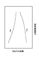
- FIG. 4 is a diagram in which the maximum preload at which the bearing can normally support the main shaft and the minimum preload at which the main shaft can normally rotate are set for each rotation speed of the main shaft.
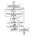
- FIG. 5 is a flowchart for explaining the operation of the spindle control device of FIG.
- FIG. 1A is a longitudinal sectional view showing the overall structure of the spindle device according to the embodiment of the present invention
- FIG. 1B is an enlarged sectional view of a portion A in FIG. It is.
- the left-right direction is the axial direction
- the left side is the front.
- the spindle device 1 according to the present embodiment includes a substantially cylindrical spindle housing 11 having an accommodation space 110 in the inner periphery, a spindle 12 disposed in the accommodation space 110, and the spindle 12.
- a radial direction displacement sensor 21 (corresponding to the “first displacement detection means” of the present invention) that detects a radial displacement of the main spindle 12 due to machining by the tool T, and an axial direction displacement sensor that detects a displacement in the axial direction. 22 (corresponding to “second displacement detecting means” of the present invention) and a speed sensor 123 (corresponding to “rotational speed detecting means” of the present invention) for detecting the rotational speed of the main shaft 12.
- a rod hole 121 extending in the axial direction is formed at the center of the rotation axis of the main spindle 12.
- the rod hole 121 penetrates the main shaft 12 in the axial direction, and a tool attaching taper portion 121a is formed at the front end.
- a collet housing part 121b is formed behind the tool mounting taper part 121a, and a spring housing hole 121c having a diameter larger than that of the collet housing part 121b is formed behind the collet housing part 121b.
- a sleeve 122 is fixed to the front end portion of the spring accommodating hole 121c.
- the rod 15 is accommodated in the rod hole 121 so as to be movable in the axial direction.
- a stopper 152 having a larger diameter than that of the shaft member 151 is fixed to the rear end portion of the long shaft member 151. Further, a collet 153 is attached to the front end of the rod 15. The collet 153 is provided so as to be able to expand and contract in the radial direction, and is formed so that the tool T can be gripped.
- a hydraulic cylinder 17 having a cylinder housing 171 integrated with the main shaft housing 11 and a piston 172 provided in the cylinder housing 171 so as to be movable in the axial direction is provided behind the main shaft 12.
- the two pairs of first and second front rolling bearings 131 and 132 are angular contact bearings, and are juxtaposed in the axial direction on the front side in the housing space 110 of the front spindle housing 11a, and the rear rolling bearing 133 is
- the cylindrical roller bearing is disposed on the rear side in the accommodation space 110.
- the first and second front rolling bearings 131 and 132 support the front side of the main shaft 12 on the tool T side, and the rear rolling bearing 133 supports the rear side of the tool T behind the front side of the main shaft 12. Bearing.
- cylindrical spacers 112a, 112b and 112c are provided between the inner rings of the pair of first front rolling bearings 131, between the inner rings of the pair of second front rolling bearings 132, and between the inner rings of the first front rolling bearing 131 and the second front rolling bearing 132.
- the outer peripheral surface of the main shaft 12 is fitted to the inner peripheral portions of the first and second front rolling bearings 131 and 132 and the spacers 112a, 112b, and 112c.
- the inner ring of the first front rolling bearing 131 located at the forefront is in contact with the flange portion 12a formed at the front end of the main shaft 12, and the inner ring of the second front rolling bearing 132 located at the rear is A cylindrical inner ring presser 113 that is screwed onto the outer peripheral surface of the main shaft 12 is in contact therewith. Accordingly, the first and second front rolling bearings 131 and 132 and the spacers 112a, 112b, and 112c are fixed to the outer peripheral surface of the main shaft 12.
- Cylindrical spacers 112d and 112e are disposed between the outer rings of the pair of first front rolling bearings 131 and between the outer rings of the pair of second front rolling bearings 132.
- the first and second front rolling bearings 131 and 132 and the spacers 112d and 112e are supported by the bearing support tube 111.
- the bearing support cylinder 111 includes a substantially cylindrical sleeve 114, a substantially annular outer ring presser 115, and a substantially cylindrical piston 116.
- a circumferential convex portion 114a that protrudes inward is formed on a substantially central inner peripheral portion of the collar sleeve 114, and a flange portion 114c that protrudes outward is formed on a substantially central outer peripheral portion.
- the inner diameter of the inner peripheral portion on the front side of the circumferential convex portion 114a of the sleeve 114 is formed substantially the same as the outer diameter of the first front rolling bearing 131 and the spacer 112d, and the inner diameter of the inner peripheral portion on the rear side of the circumferential convex portion 114a. Is formed substantially the same as the outer diameter of the piston 116.
- the outer diameter of the outer peripheral portion on the front side of the flange portion 114c of the sleeve 114 is formed to be substantially the same as the inner diameter of one of the two divided front spindle housings 11a (first front spindle housing 11aa) and more than the flange portion 114c.
- the outer diameter of the outer peripheral portion on the rear side is formed substantially the same as the inner diameter of the other of the front spindle housing 11a divided into two (second front spindle housing 11ab).
- a boss portion 115 a protruding in the axial direction is formed on one end surface of the outer ring presser 115.
- the outer diameter of the boss 115a of the outer ring retainer 115 is formed to be substantially the same as the inner diameter of the inner peripheral portion on the front side of the circumferential convex portion 114a of the sleeve 114 (the outer diameter of the first front rolling bearing 131 and the spacer 112d).
- the outer diameter of the outer ring retainer 115 is formed to be substantially the same as the outer diameter of the first front main shaft housing 11aa.
- a circumferential convex portion 116 a protruding inward is formed on the front inner peripheral portion of the piston 116.
- the inner diameter of the inner peripheral portion on the rear side of the circumferential convex portion 116a of the piston 116 is formed to be substantially the same as the outer diameters of the second front rolling bearing 132 and the spacer 112e.
- the first front rolling bearing 131 and the spacer 112d are fitted to the inner peripheral portion of the sleeve 114 on the front side of the circumferential convex portion 114a.
- a second front rolling bearing 132 and a spacer 112e are fitted to the inner peripheral portion on the rear side of the circumferential convex portion 116a of the piston 116.
- the outer peripheral surface of the piston 116 is liquid-tightly fitted to the inner peripheral portion on the rear side of the circumferential convex portion 114a of the sleeve 114.
- the first front main shaft housing 11aa is fitted on the outer peripheral portion of the sleeve 114 in front of the flange portion 114c, and the second front main shaft housing 11ab is fitted in the outer peripheral portion on the rear side of the flange portion 114c. ing.
- the outer ring of the first front rolling bearing 131 located at the front is brought into contact with the boss 115a of the outer ring presser 115, and the outer ring of the first front rolling bearing 131 located at the rear is brought into contact with the circumferential convex portion 114a of the sleeve 114. It is in contact.
- the outer ring of the second front rolling bearing 132 located in the front is in contact with the circumferential convex portion 116a of the piston 116, and the outer ring of the second front rolling bearing 132 located in the rear is in a free state.
- the sleeve 114, the first front main shaft housing 11aa, the second front main shaft housing 11ab, and the outer ring retainer 115 are fastened and integrated by a bolt (not shown) penetrating from the front end surface of the outer ring retainer 115, and the second front main shaft.
- a housing 11ab is fastened to and integrated with a rear main shaft housing 11b (11) accommodating the built-in motor 14 by bolts (not shown).
- a step 116b having a small diameter portion and a large diameter portion is formed on the front outer peripheral surface of the piston 116, and the inner peripheral surface on the rear side of the circumferential convex portion 114a of the sleeve 114.
- a step 114b composed of a large diameter portion and a small diameter portion in which the small diameter portion and the large diameter portion of the piston 116 can be fitted.
- An annular hydraulic cylinder 31 is formed between the steps 116b and 114b.
- the hydraulic cylinder 31 communicates with an oil passage 32 drilled from the outer peripheral surface of a flange portion 114 c formed on the substantially outer peripheral side of the sleeve 114.
- a pipe line 33 connected to the preload applying device 3 is connected to the oil path 32.
- the heel preload applying device 3 includes a hydraulic pump 34, a pressure reducing valve 35, and a relief valve 36, and supplies hydraulic pressure to the hydraulic cylinder 31. That is, the maximum hydraulic pressure from the hydraulic pump 34 is controlled by the relief valve 36, and an arbitrary hydraulic pressure is controlled by the pressure reducing valve 35 within the range up to the maximum hydraulic pressure, and is supplied to the hydraulic cylinder 31 through the pipe line 33 and the oil path 32. .
- the hydraulic cylinder 31 generates hydraulic pressure in the axial direction (front and rear), and the piston 116 is pressed rearward to press the outer ring of the second front rolling bearing 132, so that the second front rolling bearing 132 includes Preload is applied, and the main shaft 12 moves rearward to press the inner ring of the first front rolling bearing 131, so that preload is also applied to the first front rolling bearing 131.
- a stator 141 of a built-in motor 14 is attached to the inner peripheral surface of the main spindle housing 11.
- a rotor 142 formed on the outer peripheral surface of the main shaft 12 is opposed to the inner side in the radial direction of the stator 141.
- the spindle device 1 rotates the spindle 12 with the tool T attached to the tip, and processes a workpiece (not shown).
- the rotational speed of the main shaft 12 is detected by a non-contact type speed sensor 123 disposed behind the main shaft 12.
- the radial direction displacement sensor 21 is a non-contact type sensor that detects a change in the state of the main shaft 2 associated with machining by the tool T, that is, a displacement in the radial direction of the main shaft 12.
- the axial direction displacement sensor 22 is a non-contact type sensor that detects a change in the state of the main shaft 2 associated with machining by the tool T, that is, a displacement in the axial direction of the main shaft 12.
- the radial direction displacement sensor 21 is disposed in a hole formed in the radial direction from the outer peripheral surface of the outer ring presser 115.
- the axial direction displacement sensor 22 is disposed in a groove provided in the axial direction from the front end surface of the outer ring presser 115 along the inner peripheral surface.
- the radial direction displacement sensor 21 is disposed in front of the first front rolling bearing 131 and at a position as close as possible to the tool T. Further, it is desirable to close the groove and the opening of the hole so that both displacement sensors 21 and 22 are not affected by the coolant.
- an axial direction load sensor such as a force sensor that measures a direct load may be disposed in the vicinity of the outer ring of the first front rolling bearing 131.
- the spindle control device 4 includes two pairs of first and second front rolling bearings 131 and 132 and a rear rolling bearing based on the detected values of the radial direction displacement sensor 21 and the axial direction displacement sensor 22.
- a radial direction load calculation unit 41 (corresponding to the “first load calculation unit” of the present invention) and an axial direction load calculation unit 42 (of the present invention) that are obtained by calculating the radial direction and axial direction loads acting on 133.
- Second load calculating means corresponds to “Corresponding to” second load calculating means ") and a surface pressure analyzing unit 43 (analyzing the raceway contact surface pressure of each bearing 131, 132, 133 based on the load calculated by each load calculating unit 41, 42)
- a control finger that outputs a predetermined control command based on the contact surface pressure of each of the bearings 131, 132, and 133 analyzed by the surface pressure analysis unit 43.
- a command unit 44 (corresponding to “control command means” of the present invention) and a storage unit 45 capable of storing various data are provided.
- the radial direction displacement sensor 21, the axial direction displacement sensor 22, the radial direction load calculation unit 41, and the axial direction load calculation unit 42 correspond to the “load deriving unit” of the present invention.
- the storage unit 45 includes data indicating the relationship between the load acting on the main shaft 12 and the displacement of the main shaft 12 shown in FIG. 3, and the raceway surfaces of the outer and inner rings of the bearings 131, 132, 133 and balls (cylindrical rollers).
- the contact surface area data, the track surface contact surface pressure threshold data of the bearings 131, 132, and 133, the table set as the controllable region of the preload applying device 3 shown in FIG. 4, and the like are stored. .
- each bearing 131 is obtained from the radial displacement of the main shaft 12 when a radial load (F) is applied to the main shaft 12 detected by one radial direction displacement sensor 21.
- a radial load (F) is applied to the main shaft 12 detected by one radial direction displacement sensor 21.
- 132, 133 can be obtained at the disposition positions P1, P2, P3, P4, P5, and the radial loads acting on the bearings 131, 132, 133 can be obtained. Therefore, it is possible to accurately grasp the loads acting on the bearings 131, 132, and 133 that support the main shaft 12 in machining with the tool T.
- the table shown in FIG. 4 shows a maximum preload Pmax at which the first and second front rolling bearings 131 and 132 can normally support the main shaft 12 and a minimum preload Pmin at which the main shaft 12 can normally rotate for each rotational speed of the main shaft 12.
- the region between the maximum preload Pmax and the minimum preload Pmin is set as a controllable region of the preload applying device 3.
- the maximum preload Pmax is set to change small as the rotation speed of the main shaft 12 increases, and the minimum preload Pmin is set to change greatly as the rotation speed of the main shaft 12 increases.
- the maximum preload Pmax set for each rotational speed of the main shaft 12 is a limit value that can secure the rigidity of the first and second front rolling bearings 131 and 132 to maximize the rigidity of the main shaft 12, and for each rotational speed of the main shaft 12.
- the minimum preload Pmin set to is a limit value that can prevent the heat generation and the excessive increase in the surface pressure and can maximize the life of the first and second front rolling bearings 131 and 132.
- the radial load calculation unit 41 reads the model from the storage unit 45, analyzes the radial displacement of the main shaft 12 detected by the radial direction displacement sensor 21 by the transfer matrix method, and further applies the preload applying device 3. By adding the preload, the radial load acting on each of the bearings 131, 132, 133 is obtained.
- the axial direction load calculating unit 42 calculates by the Hooke's law using the axial displacement of the main shaft 12 detected by the axial direction displacement sensor 22, and further takes into account the preload applied by the preload applying device 3. An axial load acting on each of the bearings 131, 132, 133 (same for each of the bearings 131, 132, 133) is obtained.
- the surface pressure analysis unit 43 applies the bearings 131, 132, 132 obtained from the rotational speed of the main shaft 12 detected by the speed sensor 123 to the loads acting on the bearings 131, 132, 133 from the load calculation units 41, 42.
- the area of the raceway contact surface of each bearing 131, 132, 133 read from the storage unit 45 is used to contact the raceway surface of each bearing 131, 132, 133. Find the surface pressure.
- the rotational speed of the main shaft 12 is a low speed equal to or lower than a certain speed, the influence of the centrifugal force is small and the centrifugal force need not be taken into account.
- the control command unit 44 calculates the raceway surface contact surface pressure of each bearing 131, 132, 133 from the surface pressure analysis unit 43 and the threshold value of the raceway surface contact surface pressure of each bearing 131, 132, 133 read from the storage unit 45. Compare. And, for example, when the sharpness of the tool T is reduced or the machining allowance is changed due to variations in the dimensional accuracy of the material shape, and the state of the spindle 12 is changed, at least one of the obtained raceway surface contact surface pressures has a threshold value. When exceeded, the main control device of the machine tool is instructed to change the machining conditions, and when at least one of the obtained raceway contact surface pressures exceeds the threshold even if the machining conditions are changed, the spindle 12 is stopped. To the main controller of the machine tool. Therefore, seizure of each bearing 131, 132, 133 can be prevented.
- machining of the work material is started under the machining conditions commanded by the NC program, such as the rotational speed, preload, feed speed, cutting depth, cutting width, etc. of the tool T (spindle 12) (step 1). Then, the radial and axial displacements of the main shaft 12 detected by the radial and axial direction displacement sensors 21 and 22 are input (step 2).
- the radial displacement of the main shaft 12 is analyzed by the transfer matrix method based on the model, and further the preload is added to obtain the radial load acting on each of the bearings 131, 132, 133 and the axial direction of the main shaft 12
- the axial load acting on each of the bearings 131, 132, 133 is obtained by calculating with the Hooke's law using the above displacement and adding the preload (step 3).
- the radial force and the axial load acting on the bearings 131, 132, 133 are added to the centrifugal force acting on the balls (cylindrical rollers) of the bearings 131, 132, 133 obtained from the rotational speed of the main shaft 12.
- the raceway surface contact surface pressure of each bearing 131, 132, 133 is obtained using the area of the raceway surface contact surface of each bearing 131, 132, 133 (step 4).
- size of the track surface contact surface pressure of each bearing 131,132,133 and the threshold value of the track surface contact surface pressure of each bearing 131,132,133 is compared (step 5).
- step 5 when at least one of the obtained raceway surface contact surface pressures exceeds a threshold value, it is determined whether or not the machining conditions are to be changed (step 6). If the machining conditions are to be changed, the main control of the machine tool is determined. The apparatus is instructed to change the machining conditions (step 7), and the process returns to step 1 to repeat the above-described processing.
- a change in which the rotational speed of the tool T (spindle 12) is reduced at a preset reduction rate a change in which the preload is lowered at a preset reduction rate within the preload range, and a feed rate is reduced at a preset reduction rate.
- a change to be performed a change to reduce the cutting depth at a preset reduction rate, a change to reduce the cutting width at a preset reduction rate, and the like.
- the spindle device 1 including the preload applying device 3 that controls the preload has been described.
- the present invention is similarly applied to a spindle device that does not include the preload applying device 3. The effect of can be obtained.
Landscapes
- Engineering & Computer Science (AREA)
- Mechanical Engineering (AREA)
- Rolling Contact Bearings (AREA)
- Turning (AREA)
- Machine Tool Sensing Apparatuses (AREA)
- Numerical Control (AREA)
- Automatic Control Of Machine Tools (AREA)
- Mounting Of Bearings Or Others (AREA)
Priority Applications (3)
| Application Number | Priority Date | Filing Date | Title |
|---|---|---|---|
| CN201080042090.0A CN102510956B (zh) | 2009-09-24 | 2010-09-22 | 机床的主轴装置 |
| EP10818813.7A EP2481941B1 (en) | 2009-09-24 | 2010-09-22 | Spindle device of machining center |
| US13/390,654 US9020629B2 (en) | 2009-09-24 | 2010-09-22 | Main spindle device of machine tool |
Applications Claiming Priority (2)
| Application Number | Priority Date | Filing Date | Title |
|---|---|---|---|
| JP2009219026A JP5418110B2 (ja) | 2009-09-24 | 2009-09-24 | 工作機械の主軸装置 |
| JP2009-219026 | 2009-09-24 |
Publications (1)
| Publication Number | Publication Date |
|---|---|
| WO2011037140A1 true WO2011037140A1 (ja) | 2011-03-31 |
Family
ID=43795886
Family Applications (1)
| Application Number | Title | Priority Date | Filing Date |
|---|---|---|---|
| PCT/JP2010/066415 WO2011037140A1 (ja) | 2009-09-24 | 2010-09-22 | 工作機械の主軸装置 |
Country Status (5)
| Country | Link |
|---|---|
| US (1) | US9020629B2 (zh) |
| EP (1) | EP2481941B1 (zh) |
| JP (1) | JP5418110B2 (zh) |
| CN (1) | CN102510956B (zh) |
| WO (1) | WO2011037140A1 (zh) |
Families Citing this family (12)
| Publication number | Priority date | Publication date | Assignee | Title |
|---|---|---|---|---|
| WO2013088849A1 (ja) * | 2011-12-16 | 2013-06-20 | 株式会社日立製作所 | 切削加工装置及びそれを用いた加工方法 |
| KR101366140B1 (ko) * | 2013-06-10 | 2014-02-25 | 주식회사 에코텍 | 예압조정을 위한 스트로크의 극간 및 실링재의 탄성변형을 이용한 베어링의 가변 예압 시스템 |
| JP6029576B2 (ja) * | 2013-12-20 | 2016-11-24 | 株式会社神戸製鋼所 | 密閉式混練装置のロータに加わるスラスト荷重の計測装置 |
| JP6179547B2 (ja) * | 2014-05-20 | 2017-08-16 | 日本精工株式会社 | 玉軸受の検査装置及び検査方法 |
| JP6434246B2 (ja) * | 2014-07-29 | 2018-12-05 | ファナック株式会社 | 機械異常履歴の解析支援機能を有する数値制御装置 |
| JP6381665B2 (ja) * | 2014-10-29 | 2018-08-29 | 株式会社牧野フライス製作所 | 工作機械の制御方法および工作機械の制御装置 |
| JP6372383B2 (ja) | 2015-02-09 | 2018-08-15 | スター精密株式会社 | 工作機械 |
| JP6502128B2 (ja) * | 2015-03-10 | 2019-04-17 | Ntn株式会社 | 主軸装置 |
| DE102016013890A1 (de) * | 2016-11-21 | 2018-05-24 | Rheinisch-Westfälische Technische Hochschule (Rwth) Aachen | Verfahren zur Bestimmung der Achslast auf Linear- und Rundachsen |
| DE102017124667A1 (de) * | 2017-10-23 | 2019-04-25 | Schaeffler Technologies AG & Co. KG | Messsystem zur Überwachung einer Spindel |
| US10534345B2 (en) * | 2017-12-08 | 2020-01-14 | Wei-Ting Lin | Spindle with intelligent auto-detection system |
| JP6948928B2 (ja) * | 2017-12-08 | 2021-10-13 | 芝浦機械株式会社 | 主軸装置および工作機械 |
Citations (6)
| Publication number | Priority date | Publication date | Assignee | Title |
|---|---|---|---|---|
| JPH08118184A (ja) * | 1994-10-20 | 1996-05-14 | Seiko Seiki Co Ltd | スピンドル装置 |
| JPH0953596A (ja) * | 1995-08-18 | 1997-02-25 | Ebara Corp | 多段ポンプとその流体加振力の低減方法 |
| JP2002001633A (ja) | 2000-06-19 | 2002-01-08 | Murata Mach Ltd | 異常負荷検知機能を備えた加工機 |
| JP2004084737A (ja) * | 2002-08-26 | 2004-03-18 | Koyo Seiko Co Ltd | 転がり軸受 |
| WO2008047424A1 (en) * | 2006-10-18 | 2008-04-24 | Hitachi Zosen Corporation | Method and device for evaluating shafting alignment of ship |
| JP2009061571A (ja) | 2007-09-10 | 2009-03-26 | Ntn Corp | 工作機械主軸用スピンドル装置 |
Family Cites Families (16)
| Publication number | Priority date | Publication date | Assignee | Title |
|---|---|---|---|---|
| US4514123A (en) * | 1981-10-29 | 1985-04-30 | Kearney & Trecker Corporation | Adaptive control system for machine tool or the like |
| JP2701927B2 (ja) * | 1989-03-20 | 1998-01-21 | 株式会社日立製作所 | 可変速スクロール圧縮機 |
| GB9315843D0 (en) * | 1993-07-30 | 1993-09-15 | Litton Uk Ltd | Improved machine tool |
| JPH0825106A (ja) * | 1994-07-18 | 1996-01-30 | Honda Motor Co Ltd | 軸受の予圧調整装置 |
| JPH09192904A (ja) * | 1996-01-18 | 1997-07-29 | Toshiba Mach Co Ltd | 空気軸受式工作機械 |
| JPH1034494A (ja) * | 1996-07-22 | 1998-02-10 | Okuma Mach Works Ltd | 軸受装置 |
| JPH1043909A (ja) * | 1996-07-30 | 1998-02-17 | Nippon Seiko Kk | 回転体駆動装置 |
| US5952587A (en) * | 1998-08-06 | 1999-09-14 | The Torrington Company | Imbedded bearing life and load monitor |
| JP2000145794A (ja) * | 1998-11-06 | 2000-05-26 | Mitsubishi Heavy Ind Ltd | 超高速・高剛性転がり軸受 |
| DE102007044458B4 (de) * | 2007-09-10 | 2015-05-13 | Mag Ias Gmbh | Verfahren zur Sitzprüfung oder Unwuchtprüfung eines Werkzeugs |
| US8613303B1 (en) * | 2008-07-17 | 2013-12-24 | Hunter Engineering Company | Tire changing machine with force detection and control methods |
| US9427843B2 (en) * | 2008-02-21 | 2016-08-30 | Mori Seiki Co., Ltd | Measuring apparatus and method |
| US8695763B2 (en) * | 2008-03-26 | 2014-04-15 | Haas Automation, Inc. | Smart machine tool lubrication system |
| JP2010162634A (ja) | 2009-01-14 | 2010-07-29 | Jtekt Corp | 主軸装置 |
| JP5742312B2 (ja) * | 2011-03-10 | 2015-07-01 | 株式会社ジェイテクト | びびり振動検出方法 |
| JP5966651B2 (ja) * | 2012-06-19 | 2016-08-10 | 株式会社ジェイテクト | 主軸装置 |
-
2009
- 2009-09-24 JP JP2009219026A patent/JP5418110B2/ja not_active Expired - Fee Related
-
2010
- 2010-09-22 EP EP10818813.7A patent/EP2481941B1/en not_active Not-in-force
- 2010-09-22 WO PCT/JP2010/066415 patent/WO2011037140A1/ja active Application Filing
- 2010-09-22 CN CN201080042090.0A patent/CN102510956B/zh not_active Expired - Fee Related
- 2010-09-22 US US13/390,654 patent/US9020629B2/en not_active Expired - Fee Related
Patent Citations (6)
| Publication number | Priority date | Publication date | Assignee | Title |
|---|---|---|---|---|
| JPH08118184A (ja) * | 1994-10-20 | 1996-05-14 | Seiko Seiki Co Ltd | スピンドル装置 |
| JPH0953596A (ja) * | 1995-08-18 | 1997-02-25 | Ebara Corp | 多段ポンプとその流体加振力の低減方法 |
| JP2002001633A (ja) | 2000-06-19 | 2002-01-08 | Murata Mach Ltd | 異常負荷検知機能を備えた加工機 |
| JP2004084737A (ja) * | 2002-08-26 | 2004-03-18 | Koyo Seiko Co Ltd | 転がり軸受 |
| WO2008047424A1 (en) * | 2006-10-18 | 2008-04-24 | Hitachi Zosen Corporation | Method and device for evaluating shafting alignment of ship |
| JP2009061571A (ja) | 2007-09-10 | 2009-03-26 | Ntn Corp | 工作機械主軸用スピンドル装置 |
Also Published As
| Publication number | Publication date |
|---|---|
| JP2011069405A (ja) | 2011-04-07 |
| US20120173012A1 (en) | 2012-07-05 |
| CN102510956B (zh) | 2014-12-10 |
| US9020629B2 (en) | 2015-04-28 |
| EP2481941A1 (en) | 2012-08-01 |
| CN102510956A (zh) | 2012-06-20 |
| JP5418110B2 (ja) | 2014-02-19 |
| EP2481941B1 (en) | 2019-08-21 |
| EP2481941A4 (en) | 2018-01-03 |
Similar Documents
| Publication | Publication Date | Title |
|---|---|---|
| JP5418110B2 (ja) | 工作機械の主軸装置 | |
| JP5560603B2 (ja) | 主軸装置 | |
| JP5644082B2 (ja) | 工作機械の主軸装置 | |
| JP2011079078A5 (zh) | ||
| CN201931307U (zh) | 薄板类零件外圆车夹具 | |
| JP2011069405A5 (zh) | ||
| JP5521453B2 (ja) | 工作機械 | |
| JP2009061571A (ja) | 工作機械主軸用スピンドル装置 | |
| KR20190028780A (ko) | 볼 베어링, 주축 장치 및 공작 기계 | |
| TWI601595B (zh) | Bearing device | |
| JP6000453B2 (ja) | 工作機械の主軸装置および工作機械 | |
| JP6828478B2 (ja) | 軸受装置 | |
| EP2269767B1 (en) | Spindle device for machine tool with preload adjustment of the bearing | |
| KR20170082801A (ko) | 스핀들용 베어링의 가변예압장치 | |
| US10302128B2 (en) | Combined ball bearing, main spindle device, and machine tool | |
| JP2000237902A (ja) | 主軸装置 | |
| JPH0524366B2 (zh) | ||
| JP7480256B1 (ja) | ひずみセンサ付き軸受装置および工作機械用スピンドル装置 | |
| JP2009191877A (ja) | 主軸装置用軸受 | |
| KR101866235B1 (ko) | 스핀들 전반부의 가변예압조절장치 | |
| KR101728684B1 (ko) | 스핀들 베어링의 2단 정압 예압장치 | |
| JP5560885B2 (ja) | 工作機械の主軸装置の刃具接触検出装置 | |
| JP2014000635A (ja) | 主軸装置 |
Legal Events
| Date | Code | Title | Description |
|---|---|---|---|
| WWE | Wipo information: entry into national phase |
Ref document number: 201080042090.0 Country of ref document: CN |
|
| 121 | Ep: the epo has been informed by wipo that ep was designated in this application |
Ref document number: 10818813 Country of ref document: EP Kind code of ref document: A1 |
|
| WWE | Wipo information: entry into national phase |
Ref document number: 13390654 Country of ref document: US |
|
| WWE | Wipo information: entry into national phase |
Ref document number: 2010818813 Country of ref document: EP |
|
| NENP | Non-entry into the national phase |
Ref country code: DE |