EP2481941B1 - Spindle device of machining center - Google Patents
Spindle device of machining center Download PDFInfo
- Publication number
- EP2481941B1 EP2481941B1 EP10818813.7A EP10818813A EP2481941B1 EP 2481941 B1 EP2481941 B1 EP 2481941B1 EP 10818813 A EP10818813 A EP 10818813A EP 2481941 B1 EP2481941 B1 EP 2481941B1
- Authority
- EP
- European Patent Office
- Prior art keywords
- main spindle
- bearings
- displacement
- loads
- raceway surface
- Prior art date
- Legal status (The legal status is an assumption and is not a legal conclusion. Google has not performed a legal analysis and makes no representation as to the accuracy of the status listed.)
- Not-in-force
Links
Images

Classifications
-
- B—PERFORMING OPERATIONS; TRANSPORTING
- B23—MACHINE TOOLS; METAL-WORKING NOT OTHERWISE PROVIDED FOR
- B23Q—DETAILS, COMPONENTS, OR ACCESSORIES FOR MACHINE TOOLS, e.g. ARRANGEMENTS FOR COPYING OR CONTROLLING; MACHINE TOOLS IN GENERAL CHARACTERISED BY THE CONSTRUCTION OF PARTICULAR DETAILS OR COMPONENTS; COMBINATIONS OR ASSOCIATIONS OF METAL-WORKING MACHINES, NOT DIRECTED TO A PARTICULAR RESULT
- B23Q1/00—Members which are comprised in the general build-up of a form of machine, particularly relatively large fixed members
- B23Q1/70—Stationary or movable members for carrying working-spindles for attachment of tools or work
-
- B—PERFORMING OPERATIONS; TRANSPORTING
- B23—MACHINE TOOLS; METAL-WORKING NOT OTHERWISE PROVIDED FOR
- B23Q—DETAILS, COMPONENTS, OR ACCESSORIES FOR MACHINE TOOLS, e.g. ARRANGEMENTS FOR COPYING OR CONTROLLING; MACHINE TOOLS IN GENERAL CHARACTERISED BY THE CONSTRUCTION OF PARTICULAR DETAILS OR COMPONENTS; COMBINATIONS OR ASSOCIATIONS OF METAL-WORKING MACHINES, NOT DIRECTED TO A PARTICULAR RESULT
- B23Q15/00—Automatic control or regulation of feed movement, cutting velocity or position of tool or work
- B23Q15/007—Automatic control or regulation of feed movement, cutting velocity or position of tool or work while the tool acts upon the workpiece
- B23Q15/12—Adaptive control, i.e. adjusting itself to have a performance which is optimum according to a preassigned criterion
-
- B—PERFORMING OPERATIONS; TRANSPORTING
- B23—MACHINE TOOLS; METAL-WORKING NOT OTHERWISE PROVIDED FOR
- B23Q—DETAILS, COMPONENTS, OR ACCESSORIES FOR MACHINE TOOLS, e.g. ARRANGEMENTS FOR COPYING OR CONTROLLING; MACHINE TOOLS IN GENERAL CHARACTERISED BY THE CONSTRUCTION OF PARTICULAR DETAILS OR COMPONENTS; COMBINATIONS OR ASSOCIATIONS OF METAL-WORKING MACHINES, NOT DIRECTED TO A PARTICULAR RESULT
- B23Q17/00—Arrangements for observing, indicating or measuring on machine tools
-
- F—MECHANICAL ENGINEERING; LIGHTING; HEATING; WEAPONS; BLASTING
- F16—ENGINEERING ELEMENTS AND UNITS; GENERAL MEASURES FOR PRODUCING AND MAINTAINING EFFECTIVE FUNCTIONING OF MACHINES OR INSTALLATIONS; THERMAL INSULATION IN GENERAL
- F16C—SHAFTS; FLEXIBLE SHAFTS; ELEMENTS OR CRANKSHAFT MECHANISMS; ROTARY BODIES OTHER THAN GEARING ELEMENTS; BEARINGS
- F16C2233/00—Monitoring condition, e.g. temperature, load, vibration
-
- G—PHYSICS
- G05—CONTROLLING; REGULATING
- G05B—CONTROL OR REGULATING SYSTEMS IN GENERAL; FUNCTIONAL ELEMENTS OF SUCH SYSTEMS; MONITORING OR TESTING ARRANGEMENTS FOR SUCH SYSTEMS OR ELEMENTS
- G05B2219/00—Program-control systems
- G05B2219/30—Nc systems
- G05B2219/49—Nc machine tool, till multiple
- G05B2219/49044—Control preload of spindle bearing
-
- G—PHYSICS
- G05—CONTROLLING; REGULATING
- G05B—CONTROL OR REGULATING SYSTEMS IN GENERAL; FUNCTIONAL ELEMENTS OF SUCH SYSTEMS; MONITORING OR TESTING ARRANGEMENTS FOR SUCH SYSTEMS OR ELEMENTS
- G05B2219/00—Program-control systems
- G05B2219/30—Nc systems
- G05B2219/49—Nc machine tool, till multiple
- G05B2219/49086—Adjust feeding speed or rotational speed of main spindle when load out of range
-
- G—PHYSICS
- G05—CONTROLLING; REGULATING
- G05B—CONTROL OR REGULATING SYSTEMS IN GENERAL; FUNCTIONAL ELEMENTS OF SUCH SYSTEMS; MONITORING OR TESTING ARRANGEMENTS FOR SUCH SYSTEMS OR ELEMENTS
- G05B2219/00—Program-control systems
- G05B2219/30—Nc systems
- G05B2219/50—Machine tool, machine tool null till machine tool work handling
- G05B2219/50186—Diagnostic of spindle bearing
-
- Y—GENERAL TAGGING OF NEW TECHNOLOGICAL DEVELOPMENTS; GENERAL TAGGING OF CROSS-SECTIONAL TECHNOLOGIES SPANNING OVER SEVERAL SECTIONS OF THE IPC; TECHNICAL SUBJECTS COVERED BY FORMER USPC CROSS-REFERENCE ART COLLECTIONS [XRACs] AND DIGESTS
- Y10—TECHNICAL SUBJECTS COVERED BY FORMER USPC
- Y10T—TECHNICAL SUBJECTS COVERED BY FORMER US CLASSIFICATION
- Y10T29/00—Metal working
- Y10T29/51—Plural diverse manufacturing apparatus including means for metal shaping or assembling
- Y10T29/5168—Multiple-tool holder
- Y10T29/5171—Axial tool and transversely movable slide rest
- Y10T29/5172—Rotary tool spindle
-
- Y—GENERAL TAGGING OF NEW TECHNOLOGICAL DEVELOPMENTS; GENERAL TAGGING OF CROSS-SECTIONAL TECHNOLOGIES SPANNING OVER SEVERAL SECTIONS OF THE IPC; TECHNICAL SUBJECTS COVERED BY FORMER USPC CROSS-REFERENCE ART COLLECTIONS [XRACs] AND DIGESTS
- Y10—TECHNICAL SUBJECTS COVERED BY FORMER USPC
- Y10T—TECHNICAL SUBJECTS COVERED BY FORMER US CLASSIFICATION
- Y10T29/00—Metal working
- Y10T29/51—Plural diverse manufacturing apparatus including means for metal shaping or assembling
- Y10T29/5168—Multiple-tool holder
- Y10T29/5173—Longitudinally and transversely movable
-
- Y—GENERAL TAGGING OF NEW TECHNOLOGICAL DEVELOPMENTS; GENERAL TAGGING OF CROSS-SECTIONAL TECHNOLOGIES SPANNING OVER SEVERAL SECTIONS OF THE IPC; TECHNICAL SUBJECTS COVERED BY FORMER USPC CROSS-REFERENCE ART COLLECTIONS [XRACs] AND DIGESTS
- Y10—TECHNICAL SUBJECTS COVERED BY FORMER USPC
- Y10T—TECHNICAL SUBJECTS COVERED BY FORMER US CLASSIFICATION
- Y10T483/00—Tool changing
- Y10T483/17—Tool changing including machine tool or component
- Y10T483/1702—Rotating work machine tool [e.g., screw machine, lathe, etc.]
- Y10T483/1705—Tool support comprises rotary spindle
-
- Y—GENERAL TAGGING OF NEW TECHNOLOGICAL DEVELOPMENTS; GENERAL TAGGING OF CROSS-SECTIONAL TECHNOLOGIES SPANNING OVER SEVERAL SECTIONS OF THE IPC; TECHNICAL SUBJECTS COVERED BY FORMER USPC CROSS-REFERENCE ART COLLECTIONS [XRACs] AND DIGESTS
- Y10—TECHNICAL SUBJECTS COVERED BY FORMER USPC
- Y10T—TECHNICAL SUBJECTS COVERED BY FORMER US CLASSIFICATION
- Y10T483/00—Tool changing
- Y10T483/17—Tool changing including machine tool or component
- Y10T483/1733—Rotary spindle machine tool [e.g., milling machine, boring, machine, grinding machine, etc.]
- Y10T483/1736—Tool having specific mounting or work treating feature
- Y10T483/1743—Tool having specific mounting or work treating feature including means for angularly orienting tool and spindle
Definitions
- the invention relates to a main spindle device used in a machine tool, or the like according to the preamble of claim 1, the features of which are known from e.g. document US 4 514 123 A .
- Document JP 2002-1633 A suggests a main spindle device in which a load sensor is provided for a drive motor of a main spindle or feed shaft, a detected load is compared with a preset load threshold and, when the detected load exceeds the load threshold, the main spindle is stopped.
- the main spindle device is able to detect a load applied to the drive motor but is not able to detect a load applied to the bearings, so the state of each bearing cannot be accurately kept track of, and there is a possibility that the bearings seize in the worst case.
- Document JP 2009-61571 A suggests a main spindle device in which a labyrinth portion is formed between a main spindle and a fixed member that supports bearings to provide a displacement sensor, a detected displacement is compared with a present displacement threshold, and then, when the detected displacement exceeds the displacement threshold, it is estimated that an excessive radial load is acting on the bearings, and the main spindle is stopped.
- this main spindle device it is possible to prevent a seizure of the bearings by avoiding an excessive load acting on the bearings.
- US 4 514 123 A is another document teaching to determine thrust forces acting on bearings.
- Document EP 2 088 074 A1 describes determining the loads of bearings in order to determine an inclination of a ship's crank shaft, intermediate shaft and propeller shaft. That is, these three elements have to be correctly aligned in order to avoid damage of the ship's structure.
- the invention is contemplated in light of the above situation, and it is the object of the invention to provide a main spindle device for a machine tool, which is able to prevent a seizure of the bearings by accurately keeping track of a load acting on all the bearings that support the main spindle.
- the feature of the configuration of the invention relates to a main spindle device for a machine tool, including: a main spindle that holds a tool and that is driven for rotation; a plurality of bearings that rotatably support the main spindle, wherein the main spindle device includes: load deriving means that derives loads that respectively act on the bearings from a variation in a state of the main spindle resulting from machining using the tool; contact pressure analyzing means that analyzes raceway surface contact pressures of the respective bearings on the basis of the loads that respectively act on the bearings and that are derived by the load deriving means; and control instruction means that compares the raceway surface contact pressures of the respective bearings, analyzed by the contact pressure analyzing means, with preset thresholds of the raceway surface contact pressures of the respective bearings, and, when at least one of the raceway surface contact pressures exceeds a corresponding one of the thresholds of the raceway surface contact pressures, issues instructions to change a machining condition or issues instructions to stop
- the load deriving means includes: first displacement detecting means that detects a radial displacement of the main spindle; second displacement detecting means that detects an axial displacement of the main spindle; first load computing means that, using the transfer-matrix method, computes radial loads that respectively act on the bearings on the basis of the radial displacement of the main spindle, detected by the first displacement detecting means; and second load computing means that, using Hooke's law, computes axial loads that respectively act on the bearings on the basis of the axial displacement of the main spindle, detected by the second displacement detecting means.
- the first load computing means analyzes the radial displacement of the main spindle, detected by the first displacement detecting means, using transfer-matrix method on the basis of a shape of the main spindle, a position of each of the bearings and a stiffness of each of the bearings, which are modeled in advance, to thereby compute the radial loads that respectively act on the bearings.
- preload application means that applies an axial preload to the bearings
- load deriving means derives the radial loads and axial loads that respectively act on the bearings by incorporating the preload that is applied by the preload application means and that acts on the bearings.
- the feature of the configuration of the invention according to claim 3 is such that, in any one of claims 1 and 2, rotation speed detecting means that detects a rotation speed of the main spindle is provided, wherein the contact pressure analyzing means analyzes the raceway surface contact pressures of the respective bearings by incorporating the centrifugal force obtained from the rotation speed of the main spindle, detected by the rotation speed detecting means.
- the loads that act on all the bearings that support the main spindle are derived from a variation in the state of the main spindle, such as a load that acts on the main spindle and that is obtained from the detected displacement of the main spindle or a directly detected load that acts on the main spindle, and, in addition, the raceway surface contact pressures of the respective bearings are analyzed, so it is possible to accurately keep track of the state of each bearing.
- the detected radial displacement of the main spindle is analyzed using the model of the shape of the main spindle, and the like, and transfer-matrix method, so it is possible to accurately compute the radial loads that respectively act on the bearings.
- the preload that acts on the bearings is also incorporated, so it is possible to further accurately derive the loads that respectively act on the bearings.
- centrifugal force that acts on the bearings because of rotation of the main spindle may be incorporated, so it is possible to further accurately analyze the raceway surface contact pressures of the respective bearings.
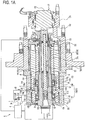
- FIG. 1A is a longitudinal sectional view that shows the overall structure of a main spindle device according to the embodiment of the invention.
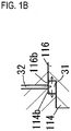
- FIG. IB is an enlarged sectional view of the portion A in FIG. 1A .
- FIG. 2 is a block diagram of a controller of the main spindle device shown in FIG. 1A . Note that, in FIG. 1A , the horizontal direction is an axial direction, and the left side is a front side. As shown in FIG.
- the main spindle device 1 includes a substantially cylindrical main spindle housing 11 having an accommodating space 110 at its inner peripheral portion, a main spindle 12 that is arranged in the accommodating space 110, two pairs of first and second front rolling bearings 131 and 132 that support the front portion of the main spindle 12, a rear rolling bearing 133 that supports the rear portion of the main spindle 12, a preload application device 3 (which corresponds to "preload application means” according to the invention) that applies a preload to the first and second front roller bearings 131 and 132 in the axial direction and a main spindle controller 4 that controls the main spindle device 1.
- a radial displacement sensor 21 (which corresponds to “first displacement detecting means” according to the invention) that detects the radial displacement of the main spindle 12 resulting from machining using a tool T
- an axial displacement sensor 22 (which corresponds to “second displacement detecting means” according to the invention) that detects the axial displacement of the main spindle 12 resulting from machining using the tool T
- a speed sensor 123 (which corresponds to "rotation speed detecting means” according to the invention) that detects the rotation speed of the main spindle 12 are provided.
- a rod hole 121 that extends in the axial direction is formed along the rotation axis center of the main spindle 12.
- the rod hole 121 extends through the main spindle 12 in the axial direction, and has a tool attachment taper portion 121a at its front end.
- a collet accommodating portion 121b is formed on the rear side of the tool attachment taper portion 121a.
- a spring accommodating hole 121c that is larger in diameter than the collet accommodating portion 121b is formed on the rear side of the collet accommodating portion 121b.
- a sleeve 122 is fixed to the front end portion of the spring accommodating hole 121c.
- a rod 15 is accommodated in the rod hole 121 so as to be movable in the axial direction.
- a stopper 152 that is larger in diameter than a long shaft member 151 is secured to the rear end portion of the shaft member 151 of the rod 15. Furthermore, a collet 153 is attached to the front end of the rod 15. The collet 153 is provided so as to expand or contract in the radial direction, and is formed to be able to hold the tool T.
- the front end portion of the shaft member 151 is slidable over the inner peripheral surface of the sleeve 122, and the stopper 152 is slidable over the spring accommodating hole 121c.
- a plurality of belleville springs 16 are interposed between the rear end portion of the sleeve 122 and the front end surface of the stopper 152 in the spring accommodating hole 121c, and the rod 15 is constantly urged rearward with respect to the main spindle 12.
- a hydraulic cylinder 17 is provided on the rear side of the main spindle 12, and has a cylinder housing 171 that is integrated with the main spindle housing 11 and a piston 172 that is provided in the cylinder housing 171 so as to be movable in the axial direction.
- the piston 172 moves rearward to release engagement between the piston 172 and the rod 15, the rod 15 that holds the tool T with the collet 153 recedes with respect to the main spindle 12 by the urging force of the belleville spring 16. Then, the tool T is fitted to the tool attachment taper portion 121a of the main spindle 12 and is fixed to the main spindle 12.
- the two pairs of first and second front rolling bearings 131 and 132 are angular contact bearings, and are aligned in the axial direction at the front side in the accommodating space 110 of the front main spindle housing 11a.
- the rear rolling bearing 133 is a cylindrical roller bearing, and is arranged at the rear side in the accommodating space 110.
- the first and second front rolling bearings 131 and 132 support the front portion, adjacent to the tool T, of the main spindle 12, and the rear rolling bearing 133 supports the rear portion that is on the rear side of the front portion of the main spindle 12 with respect to the tool T.
- Cylindrical spacers 112a, 112b and 112c are respectively arranged between the inner rings of the pair of first front rolling bearings 131, between the inner rings of the pair of second front rolling bearings 132 and between the inner ring of the first front rolling bearing 131 and the inner ring of the second front rolling bearing 132.
- the outer peripheral surface of the main spindle 12 is fitted to the inner peripheral portions of the first and second front rolling bearings 131 and 132 and spacers 112a, 112b and 112c.
- the inner ring of the first front rolling bearing 131 located at the frontmost side is in contact with a flange portion 12a formed at the front end of the main spindle 12, and a cylindrical inner ring retainer 113 screwed to the outer peripheral surface of the main spindle 12 is in contact with the inner ring of the second front rolling bearing 132 located at the rearmost side.
- the first and second front rolling bearings 131 and 132 and the spacers 112a, 112b and 112c are fixed to the outer peripheral surface of the main spindle 12.
- Cylindrical spacers 112d and 112e are respectively arranged between the outer rings of the pair of first front rolling bearings 131 and between the outer rings of the pair of second front rolling bearings 132.
- the first and second front rolling bearings 131 and 132 and the spacers 112d and 112e are supported by a bearing support cylinder 111.
- the bearing support cylinder 111 is formed of a substantially cylindrical sleeve 114, a substantially annular outer ring retainer 115 and a substantially cylindrical piston 116.
- a circumferential protruding portion 114a that protrudes inward is formed at substantially the center of the inner peripheral portion of the sleeve 114, and a flange portion 114c that protrudes outward is formed at substantially the center of the outer peripheral portion of the sleeve 114.
- the bore diameter of the inner peripheral portion of the sleeve 114 on the front side of the circumferential protruding portion 114a is formed so as to be substantially equal to the outside diameters of the first front rolling bearings 131 and spacer 112d, and the bore diameter of the inner peripheral portion of the sleeve 114 on the rear side of the circumferential protruding portion 114a is formed so as to be substantially equal to the outside diameter of the piston 116.
- the outside diameter of the outer peripheral portion of the sleeve 114 on the front side of the flange portion 114c is formed so as to be substantially equal to the bore diameter of one of the two-piece front main spindle housing 11a (first front main spindle housing 11aa), and the outside diameter of the outer peripheral portion of the sleeve 114 on the rear side of the flange portion 114c is formed so as to be substantially equal to the bore diameter of the other one of the two-piece front main spindle housing 11a (second front main spindle housing 11ab).
- a boss portion 115a that protrudes in the axial direction is formed on one of the end surfaces of the outer ring retainer 115.
- the outside diameter of the boss portion 115a of the outer ring retainer 115 is formed so as to be substantially equal to the bore diameter of the inner peripheral portion of the sleeve 114 on the front side of the circumferential protruding portion 114a (outside diameters of the first front rolling bearings 131 and spacer 112d).
- the outside diameter of the outer ring retainer 115 is formed so as to be substantially equal to the outside diameter of the first front main spindle housing 11aa.
- a circumferential protruding portion 116a that protrudes inward is formed at the front of the inner peripheral portion of the piston 116.
- the bore diameter of the inner peripheral portion of the piston 116 on the rear side of the circumferential protruding portion 116a is formed so as to be substantially equal to the outside diameters of the second front rolling bearings 132 and spacer 112e.
- first front rolling bearings 131 and the spacer 112d are fitted to the inner peripheral portion of the sleeve 114 on the front side of the circumferential protruding portion 114a.
- the second front rolling bearings 132 and the spacer 112e are fitted to the inner peripheral portion of the piston 116 on the rear side of the circumferential protruding portion 116a.
- the outer peripheral surface of the piston 116 is liquidtightly fitted to the inner peripheral portion of the sleeve 114 on the rear side of the circumferential protruding portion 114a.
- the first front main spindle housing 11aa is fitted to the outer peripheral portion of the sleeve 114 on the front side of the flange portion 114c, and the second front main spindle housing 11ab is fitted to the outer peripheral portion of the sleeve 114 on the rear side of the flange portion 114c.
- the outer ring of the first front rolling bearing 131 located at the front side is in contact with the boss portion 115a of the outer ring retainer 115, and the outer ring of the first front rolling bearing 131 located at the rear side is in contact with the circumferential protruding portion 114a of the sleeve 114.
- the outer ring of the second front rolling bearing 132 located at the front side is in contact with the circumferential protruding portion 116a of the piston 116, and the outer ring of the second front rolling bearing 132 located at the rear side is in a free state.
- the sleeve 114, the first front main spindle housing 11aa, the second front main spindle housing 11ab and the outer ring retainer 115 are integrally fastened by bolts (not shown) extended through from the front end surface of the outer ring retainer 115, and the second front main spindle housing 11ab is integrally fastened by bolts (not shown) to a rear main spindle housing 11b (11) that accommodates a built-in motor 14.
- a step 116b formed of a small-diameter portion and a large-diameter portion is formed on the outer peripheral surface of the front side of the piston 116
- a step 114b formed of a large diameter portion and a small-diameter portion to which the small-diameter portion and large-diameter portion of the piston 116 are fittable is formed on the inner peripheral surface of the sleeve 114 on the rear side of the circumferential protruding portion 114a.
- an annular hydraulic cylinder 31 is formed between the steps 116b and 114b.
- An oil passage 32 that is perforated from the outer peripheral surface of the flange portion 114c formed at substantially the center of the outer peripheral side of the sleeve 114 is in fluid communication with the hydraulic cylinder 31.
- a pipe line 33 that is connected to the preload application device 3 is connected to the oil passage 32.
- the preload application device 3 is formed of a hydraulic pump 34, a pressure reducing valve 35 and a pressure relief valve 36, and is configured to supply hydraulic pressure to the hydraulic cylinder 31. That is, a maximum hydraulic pressure from the hydraulic pump 34 is controlled by the pressure relief valve 36, and a selected hydraulic pressure is controlled by the pressure reducing valve 35 within the range up to the maximum hydraulic pressure and is supplied to the hydraulic cylinder 31 through the pipe line 33 and the oil passage 32.
- the stator 141 of the built-in motor 14 is connected to the inner peripheral surface of the main spindle housing 11.
- a rotor 142 formed on the outer peripheral surface of the main spindle 12 faces the stator 141 on the inner side in the radial direction.
- the main spindle device 1 rotates the main spindle 12 in a state where the tool T is attached to the distal end of the main spindle 12 to thereby machine a work material (not shown).
- the rotation speed of the main spindle 12 is detected by a non-contact speed sensor 123 arranged on the rear side of the main spindle 12.
- the radial displacement sensor 21 is a non-contact sensor that detects a variation in the state of the main spindle 2, that is, a radial displacement of the main spindle 12, resulting from machining using the tool T.
- the axial displacement sensor 22 is a non-contact sensor that detects a variation in the state of the main spindle 2, that is, an axial displacement of the main spindle 12, resulting from machining using the tool T.
- the radial displacement sensor 21 is arranged in a hole that is radially perforated from the outer peripheral surface of the outer ring retainer 115.
- the axial displacement sensor 22 is arranged in a groove that is axially provided along the inner peripheral surface from the front-side end surface of the outer ring retainer 115.
- the radial displacement sensor 21 is desirably arranged at a position that is on the front side of the first front rolling bearings 131 and that is close to the tool T as much as possible.
- the openings of the groove and hole are desirably closed such that both displacement sensors 21 and 22 are not influenced by coolant.
- an axial load sensor that directly measures a load such as a force sensor, may be arranged adjacent to the outer rings of the first front rolling bearings 131.
- the main spindle controller 4 includes a radial load computing unit 41 (which corresponds to "first load computing means” according to the invention) that computes and obtains radial loads that act the pairs of first and second front rolling bearings 131 and 132 and the rear rolling bearing 133 on the basis of the detected value of the radial displacement sensor 21, an axial load computing unit 42 (which corresponds to "second load computing means” according to the invention) that computes and obtains axial loads that act on the pairs of first and second front rolling bearings 131 and 132 and the rear rolling bearing 133 on the basis of the detected value of the axial displacement sensor 22, a contact pressure analyzing unit 43 (which corresponds to "contact pressure analyzing means” according to the invention) that analyzes the raceway surface contact pressures of the bearings 131, 132 and 133 on the basis of the loads computed by the load computing units 41 and 42, a control instruction unit 44 (which corresponds to "control instruction means” according to the invention) that outputs a predetermined control command
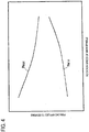
- the storage unit 45 stores data that indicates the correlation between the load that acts on the main spindle 12 shown in FIG. 3 and the displacement of the main spindle 12, data of the areas of the raceway surface contact surfaces between the outer rings and inner rings of the bearings 131, 132 and 133 and balls (cylindrical rollers), data of the thresholds of the raceway surface contact pressures of the bearings 131, 132 and 133, a table that is set as a controllable region of the preload application device 3 shown in FIG. 4 , and the like.
- the data shown in FIG. 3 models the shape of the main spindle 12, the position of each of the bearings 131, 132 and 133 and the stiffness of each of the bearings 131, 132 and 133.
- the displacements of the bearings 131, 132 and 133 at arranged positions P1, P2, P3, P4 and P5 may be obtained from the radial displacement of the main spindle 12, detected by the single radial displacement sensor 21, when the radial load (F) acts on the main spindle 12, and, in addition, the radial loads that respectively act on the bearings 131, 132 and 133 may be obtained.
- F radial load
- the table shown in FIG. 4 is such that a maximum preload Pmax at which the first and second front rolling bearings 131 and 132 are able to normally support the main spindle 12 and a minimum preload Pmin at which the main spindle 12 is able to normally rotate are set for each rotation speed of the main spindle 12 and then the region between the maximum preload Pmax and the minimum preload Pmin is set as the controllable region of the preload application device 3.
- the maximum preload Pmax is set so as to reduce as the rotation speed of the main spindle 12 increases.
- the minimum preload Pmin is set so as to increase as the rotation speed of the main spindle 12 increases.
- the maximum preload Pmax set for each rotation speed of the main spindle 12 is a limit value at which the stiffness of the main spindle 12 may be maximally increased while ensuring the stiffness of each of the first and second front rolling bearings 131 and 132.
- the minimum preload Pmin set for each rotation speed of the main spindle 12 is a limit value at which the life of each of the first and second front rolling bearings 131 and 132 may be maximally extended while preventing heat generation and an excessive increase in contact pressure.
- the radial load computing unit 41 loads the above model from the storage unit 45, analyzes the radial displacement of the main spindle 12, detected by the radial displacement sensor 21, using transfer-matrix method, and, furthermore, incorporates the preload applied by the preload application device 3 to thereby obtain the radial loads that respectively act on the bearings 131, 132 and 133.
- the axial load computing unit 42 computes using the axial displacement of the main spindle 12, detected by the axial displacement sensor 22, by Hooke's law, and, furthermore, incorporates the preload applied by the preload application device 3 to thereby obtain the axial loads (that are equal among the bearings 131, 132 and 133) that respectively act on the bearings 131, 132 and 133.
- the contact pressure analyzing unit 43 incorporates centrifugal force that acts on each of the balls (cylindrical rollers) of the bearings 131, 132 and 133, obtained from the rotation speed of the main spindle 12 detected by the speed sensor 123, into the loads that respectively act on the bearings 131, 132 and 133 and that are received from the load computing units 41 and 42 to thereby obtain the raceway surface contact pressures of the respective bearings 131, 132 and 133 using the areas of the raceway surface contact surfaces of the respective bearings 131, 132 and 133, loaded from the storage unit 45. Note that, when the rotation speed of the main spindle 12 is lower than or equal to a certain speed, the influence of centrifugal force is small, so the centrifugal force does not need to be incorporated.
- the control instruction unit 44 compares the raceway surface contact pressures of the respective bearings 131, 132 and 133 from the contact pressure analyzing unit 43 with the thresholds of the raceway surface contact pressures of the respective bearings 131, 132 and 133, loaded from the storage unit 45.
- the main controller of the machine tool is instructed to change the machining condition, and, furthermore, when at least one of the obtained raceway surface contact pressures exceeds the corresponding threshold even when the machining condition is changed, the main controller of the machine tool is instructed to stop the main spindle 12.
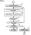
- machining a work material is started in the machining condition, such as the rotation speed, preload, feed speed, cutting amount, cutting width, and the like, of the tool T (main spindle 12), instructed by an NC program (step 1).
- the radial displacement of the main spindle 12, detected by the radial displacement sensor 21, and the axial displacement of the main spindle 12, detected by the axial displacement sensor 22, are input (step 2).
- the radial displacement of the main spindle 12 is analyzed on the basis of the model using transfer-matrix method and, furthermore, the preload is incorporated to thereby obtain the radial loads that respectively act on the bearings 131, 132 and 133, and the axial displacement of the main spindle 12 is used to compute using Hook's law and, furthermore, the preload is incorporated to thereby obtain the axial loads that respectively act on the bearings 131, 132 and 133 (step 3).
- the centrifugal force that is obtained from the rotation speed of the main spindle 12 and that acts on the balls (cylindrical rollers) of the bearings 131, 132 and 133 is incorporated into the radial and axial loads that respectively act on the bearings 131, 132 and 133 to thereby obtain the raceway surface contact pressures of the respective bearings 131, 132 and 133 using the areas of the raceway surface contact surfaces of the respective bearings 131, 132 and 133 (step 4).
- the raceway surface contact pressures of the respective bearings 131, 132 and 133 are compared with the corresponding thresholds of the raceway surface contact pressures of the respective bearings 131, 132 and 133 (step 5).
- step 5 when at least one of the obtained raceway surface contact pressures exceeds the corresponding threshold, it is determined whether the machining condition is changed (step 6). When the machining condition is changed, the main controller of the machine tool is instructed to change the machining condition (step 7), after which the process returns to step 1 to repeat the above described processes.
- step 8 the main controller of the machine tool is instructed to stop the main spindle 12 without changing the machining condition in step 6 (step 8), after which all the processes end.
- the main spindle device 1 that includes the preload application device 3 that controls the preload is described; however, even when the invention is applied to a main spindle device with no preload application device 3, similar advantageous effects may be obtained.
Landscapes
- Engineering & Computer Science (AREA)
- Mechanical Engineering (AREA)
- Rolling Contact Bearings (AREA)
- Turning (AREA)
- Machine Tool Sensing Apparatuses (AREA)
- Numerical Control (AREA)
- Automatic Control Of Machine Tools (AREA)
- Mounting Of Bearings Or Others (AREA)
Applications Claiming Priority (2)
| Application Number | Priority Date | Filing Date | Title |
|---|---|---|---|
| JP2009219026A JP5418110B2 (ja) | 2009-09-24 | 2009-09-24 | 工作機械の主軸装置 |
| PCT/JP2010/066415 WO2011037140A1 (ja) | 2009-09-24 | 2010-09-22 | 工作機械の主軸装置 |
Publications (3)
| Publication Number | Publication Date |
|---|---|
| EP2481941A1 EP2481941A1 (en) | 2012-08-01 |
| EP2481941A4 EP2481941A4 (en) | 2018-01-03 |
| EP2481941B1 true EP2481941B1 (en) | 2019-08-21 |
Family
ID=43795886
Family Applications (1)
| Application Number | Title | Priority Date | Filing Date |
|---|---|---|---|
| EP10818813.7A Not-in-force EP2481941B1 (en) | 2009-09-24 | 2010-09-22 | Spindle device of machining center |
Country Status (5)
| Country | Link |
|---|---|
| US (1) | US9020629B2 (zh) |
| EP (1) | EP2481941B1 (zh) |
| JP (1) | JP5418110B2 (zh) |
| CN (1) | CN102510956B (zh) |
| WO (1) | WO2011037140A1 (zh) |
Families Citing this family (12)
| Publication number | Priority date | Publication date | Assignee | Title |
|---|---|---|---|---|
| WO2013088849A1 (ja) * | 2011-12-16 | 2013-06-20 | 株式会社日立製作所 | 切削加工装置及びそれを用いた加工方法 |
| KR101366140B1 (ko) * | 2013-06-10 | 2014-02-25 | 주식회사 에코텍 | 예압조정을 위한 스트로크의 극간 및 실링재의 탄성변형을 이용한 베어링의 가변 예압 시스템 |
| JP6029576B2 (ja) * | 2013-12-20 | 2016-11-24 | 株式会社神戸製鋼所 | 密閉式混練装置のロータに加わるスラスト荷重の計測装置 |
| JP6179547B2 (ja) * | 2014-05-20 | 2017-08-16 | 日本精工株式会社 | 玉軸受の検査装置及び検査方法 |
| JP6434246B2 (ja) * | 2014-07-29 | 2018-12-05 | ファナック株式会社 | 機械異常履歴の解析支援機能を有する数値制御装置 |
| JP6381665B2 (ja) * | 2014-10-29 | 2018-08-29 | 株式会社牧野フライス製作所 | 工作機械の制御方法および工作機械の制御装置 |
| JP6372383B2 (ja) | 2015-02-09 | 2018-08-15 | スター精密株式会社 | 工作機械 |
| JP6502128B2 (ja) * | 2015-03-10 | 2019-04-17 | Ntn株式会社 | 主軸装置 |
| DE102016013890A1 (de) * | 2016-11-21 | 2018-05-24 | Rheinisch-Westfälische Technische Hochschule (Rwth) Aachen | Verfahren zur Bestimmung der Achslast auf Linear- und Rundachsen |
| DE102017124667A1 (de) * | 2017-10-23 | 2019-04-25 | Schaeffler Technologies AG & Co. KG | Messsystem zur Überwachung einer Spindel |
| US10534345B2 (en) * | 2017-12-08 | 2020-01-14 | Wei-Ting Lin | Spindle with intelligent auto-detection system |
| JP6948928B2 (ja) * | 2017-12-08 | 2021-10-13 | 芝浦機械株式会社 | 主軸装置および工作機械 |
Family Cites Families (22)
| Publication number | Priority date | Publication date | Assignee | Title |
|---|---|---|---|---|
| US4514123A (en) * | 1981-10-29 | 1985-04-30 | Kearney & Trecker Corporation | Adaptive control system for machine tool or the like |
| JP2701927B2 (ja) * | 1989-03-20 | 1998-01-21 | 株式会社日立製作所 | 可変速スクロール圧縮機 |
| GB9315843D0 (en) * | 1993-07-30 | 1993-09-15 | Litton Uk Ltd | Improved machine tool |
| JPH0825106A (ja) * | 1994-07-18 | 1996-01-30 | Honda Motor Co Ltd | 軸受の予圧調整装置 |
| JPH08118184A (ja) * | 1994-10-20 | 1996-05-14 | Seiko Seiki Co Ltd | スピンドル装置 |
| JPH0953596A (ja) * | 1995-08-18 | 1997-02-25 | Ebara Corp | 多段ポンプとその流体加振力の低減方法 |
| JPH09192904A (ja) * | 1996-01-18 | 1997-07-29 | Toshiba Mach Co Ltd | 空気軸受式工作機械 |
| JPH1034494A (ja) * | 1996-07-22 | 1998-02-10 | Okuma Mach Works Ltd | 軸受装置 |
| JPH1043909A (ja) * | 1996-07-30 | 1998-02-17 | Nippon Seiko Kk | 回転体駆動装置 |
| US5952587A (en) * | 1998-08-06 | 1999-09-14 | The Torrington Company | Imbedded bearing life and load monitor |
| JP2000145794A (ja) * | 1998-11-06 | 2000-05-26 | Mitsubishi Heavy Ind Ltd | 超高速・高剛性転がり軸受 |
| JP2002001633A (ja) | 2000-06-19 | 2002-01-08 | Murata Mach Ltd | 異常負荷検知機能を備えた加工機 |
| JP4221972B2 (ja) * | 2002-08-26 | 2009-02-12 | 株式会社ジェイテクト | センサ付き転がり軸受 |
| WO2008047424A1 (en) * | 2006-10-18 | 2008-04-24 | Hitachi Zosen Corporation | Method and device for evaluating shafting alignment of ship |
| DE102007044458B4 (de) * | 2007-09-10 | 2015-05-13 | Mag Ias Gmbh | Verfahren zur Sitzprüfung oder Unwuchtprüfung eines Werkzeugs |
| JP2009061571A (ja) * | 2007-09-10 | 2009-03-26 | Ntn Corp | 工作機械主軸用スピンドル装置 |
| US8613303B1 (en) * | 2008-07-17 | 2013-12-24 | Hunter Engineering Company | Tire changing machine with force detection and control methods |
| US9427843B2 (en) * | 2008-02-21 | 2016-08-30 | Mori Seiki Co., Ltd | Measuring apparatus and method |
| US8695763B2 (en) * | 2008-03-26 | 2014-04-15 | Haas Automation, Inc. | Smart machine tool lubrication system |
| JP2010162634A (ja) | 2009-01-14 | 2010-07-29 | Jtekt Corp | 主軸装置 |
| JP5742312B2 (ja) * | 2011-03-10 | 2015-07-01 | 株式会社ジェイテクト | びびり振動検出方法 |
| JP5966651B2 (ja) * | 2012-06-19 | 2016-08-10 | 株式会社ジェイテクト | 主軸装置 |
-
2009
- 2009-09-24 JP JP2009219026A patent/JP5418110B2/ja not_active Expired - Fee Related
-
2010
- 2010-09-22 EP EP10818813.7A patent/EP2481941B1/en not_active Not-in-force
- 2010-09-22 WO PCT/JP2010/066415 patent/WO2011037140A1/ja active Application Filing
- 2010-09-22 CN CN201080042090.0A patent/CN102510956B/zh not_active Expired - Fee Related
- 2010-09-22 US US13/390,654 patent/US9020629B2/en not_active Expired - Fee Related
Non-Patent Citations (1)
| Title |
|---|
| None * |
Also Published As
| Publication number | Publication date |
|---|---|
| JP2011069405A (ja) | 2011-04-07 |
| US20120173012A1 (en) | 2012-07-05 |
| CN102510956B (zh) | 2014-12-10 |
| US9020629B2 (en) | 2015-04-28 |
| EP2481941A1 (en) | 2012-08-01 |
| CN102510956A (zh) | 2012-06-20 |
| WO2011037140A1 (ja) | 2011-03-31 |
| JP5418110B2 (ja) | 2014-02-19 |
| EP2481941A4 (en) | 2018-01-03 |
Similar Documents
| Publication | Publication Date | Title |
|---|---|---|
| EP2481941B1 (en) | Spindle device of machining center | |
| EP2278181B1 (en) | Spindle device | |
| US8827609B2 (en) | Spindle device for machine tool | |
| JP4874756B2 (ja) | 工作機械 | |
| US20080093175A1 (en) | Spindle device | |
| EP3604843B1 (en) | Main shaft device | |
| US6505972B1 (en) | Bearing with adjustable setting | |
| JP2008057657A (ja) | Nc自動旋盤の主軸軸受構造 | |
| JP5521453B2 (ja) | 工作機械 | |
| JP2009061571A (ja) | 工作機械主軸用スピンドル装置 | |
| KR20190028780A (ko) | 볼 베어링, 주축 장치 및 공작 기계 | |
| TWI601595B (zh) | Bearing device | |
| JP6828478B2 (ja) | 軸受装置 | |
| EP2269767A1 (en) | Spindle device for machine tool with preload adjustment of the bearing | |
| CN108856739B (zh) | 一种自动调节主轴轴系预紧力的控制装置、系统、方法及装置 | |
| KR20170082801A (ko) | 스핀들용 베어링의 가변예압장치 | |
| JP2000237902A (ja) | 主軸装置 | |
| US10302128B2 (en) | Combined ball bearing, main spindle device, and machine tool | |
| KR20160041658A (ko) | 스핀들 장치 | |
| US5667157A (en) | Bearing clearance adjustment | |
| JP2002054631A (ja) | 主軸装置及び該装置の予圧調整方法 | |
| JP2004036748A (ja) | 主軸装置及び予圧制御方法 | |
| KR101866235B1 (ko) | 스핀들 전반부의 가변예압조절장치 | |
| KR101728684B1 (ko) | 스핀들 베어링의 2단 정압 예압장치 | |
| JP2011033170A (ja) | 流体軸受装置 |
Legal Events
| Date | Code | Title | Description |
|---|---|---|---|
| PUAI | Public reference made under article 153(3) epc to a published international application that has entered the european phase |
Free format text: ORIGINAL CODE: 0009012 |
|
| 17P | Request for examination filed |
Effective date: 20120223 |
|
| AK | Designated contracting states |
Kind code of ref document: A1 Designated state(s): AL AT BE BG CH CY CZ DE DK EE ES FI FR GB GR HR HU IE IS IT LI LT LU LV MC MK MT NL NO PL PT RO SE SI SK SM TR |
|
| DAX | Request for extension of the european patent (deleted) | ||
| RA4 | Supplementary search report drawn up and despatched (corrected) |
Effective date: 20171204 |
|
| RIC1 | Information provided on ipc code assigned before grant |
Ipc: F16C 19/52 20060101AFI20171127BHEP Ipc: B23Q 15/12 20060101ALI20171127BHEP Ipc: B23Q 1/70 20060101ALI20171127BHEP Ipc: B23B 19/02 20060101ALI20171127BHEP Ipc: B23Q 17/00 20060101ALI20171127BHEP Ipc: B23Q 5/58 20060101ALI20171127BHEP Ipc: F16C 41/00 20060101ALI20171127BHEP Ipc: G05B 19/18 20060101ALI20171127BHEP |
|
| STAA | Information on the status of an ep patent application or granted ep patent |
Free format text: STATUS: EXAMINATION IS IN PROGRESS |
|
| 17Q | First examination report despatched |
Effective date: 20180814 |
|
| GRAP | Despatch of communication of intention to grant a patent |
Free format text: ORIGINAL CODE: EPIDOSNIGR1 |
|
| STAA | Information on the status of an ep patent application or granted ep patent |
Free format text: STATUS: GRANT OF PATENT IS INTENDED |
|
| INTG | Intention to grant announced |
Effective date: 20190403 |
|
| GRAS | Grant fee paid |
Free format text: ORIGINAL CODE: EPIDOSNIGR3 |
|
| GRAA | (expected) grant |
Free format text: ORIGINAL CODE: 0009210 |
|
| STAA | Information on the status of an ep patent application or granted ep patent |
Free format text: STATUS: THE PATENT HAS BEEN GRANTED |
|
| AK | Designated contracting states |
Kind code of ref document: B1 Designated state(s): AL AT BE BG CH CY CZ DE DK EE ES FI FR GB GR HR HU IE IS IT LI LT LU LV MC MK MT NL NO PL PT RO SE SI SK SM TR |
|
| REG | Reference to a national code |
Ref country code: GB Ref legal event code: FG4D |
|
| REG | Reference to a national code |
Ref country code: CH Ref legal event code: EP |
|
| REG | Reference to a national code |
Ref country code: DE Ref legal event code: R096 Ref document number: 602010060699 Country of ref document: DE |
|
| REG | Reference to a national code |
Ref country code: AT Ref legal event code: REF Ref document number: 1170099 Country of ref document: AT Kind code of ref document: T Effective date: 20190915 |
|
| REG | Reference to a national code |
Ref country code: IE Ref legal event code: FG4D |
|
| REG | Reference to a national code |
Ref country code: LT Ref legal event code: MG4D |
|
| REG | Reference to a national code |
Ref country code: NL Ref legal event code: MP Effective date: 20190821 |
|
| PG25 | Lapsed in a contracting state [announced via postgrant information from national office to epo] |
Ref country code: PT Free format text: LAPSE BECAUSE OF FAILURE TO SUBMIT A TRANSLATION OF THE DESCRIPTION OR TO PAY THE FEE WITHIN THE PRESCRIBED TIME-LIMIT Effective date: 20191223 Ref country code: NO Free format text: LAPSE BECAUSE OF FAILURE TO SUBMIT A TRANSLATION OF THE DESCRIPTION OR TO PAY THE FEE WITHIN THE PRESCRIBED TIME-LIMIT Effective date: 20191121 Ref country code: SE Free format text: LAPSE BECAUSE OF FAILURE TO SUBMIT A TRANSLATION OF THE DESCRIPTION OR TO PAY THE FEE WITHIN THE PRESCRIBED TIME-LIMIT Effective date: 20190821 Ref country code: HR Free format text: LAPSE BECAUSE OF FAILURE TO SUBMIT A TRANSLATION OF THE DESCRIPTION OR TO PAY THE FEE WITHIN THE PRESCRIBED TIME-LIMIT Effective date: 20190821 Ref country code: LT Free format text: LAPSE BECAUSE OF FAILURE TO SUBMIT A TRANSLATION OF THE DESCRIPTION OR TO PAY THE FEE WITHIN THE PRESCRIBED TIME-LIMIT Effective date: 20190821 Ref country code: FI Free format text: LAPSE BECAUSE OF FAILURE TO SUBMIT A TRANSLATION OF THE DESCRIPTION OR TO PAY THE FEE WITHIN THE PRESCRIBED TIME-LIMIT Effective date: 20190821 Ref country code: BG Free format text: LAPSE BECAUSE OF FAILURE TO SUBMIT A TRANSLATION OF THE DESCRIPTION OR TO PAY THE FEE WITHIN THE PRESCRIBED TIME-LIMIT Effective date: 20191121 Ref country code: NL Free format text: LAPSE BECAUSE OF FAILURE TO SUBMIT A TRANSLATION OF THE DESCRIPTION OR TO PAY THE FEE WITHIN THE PRESCRIBED TIME-LIMIT Effective date: 20190821 |
|
| PG25 | Lapsed in a contracting state [announced via postgrant information from national office to epo] |
Ref country code: AL Free format text: LAPSE BECAUSE OF FAILURE TO SUBMIT A TRANSLATION OF THE DESCRIPTION OR TO PAY THE FEE WITHIN THE PRESCRIBED TIME-LIMIT Effective date: 20190821 Ref country code: LV Free format text: LAPSE BECAUSE OF FAILURE TO SUBMIT A TRANSLATION OF THE DESCRIPTION OR TO PAY THE FEE WITHIN THE PRESCRIBED TIME-LIMIT Effective date: 20190821 Ref country code: ES Free format text: LAPSE BECAUSE OF FAILURE TO SUBMIT A TRANSLATION OF THE DESCRIPTION OR TO PAY THE FEE WITHIN THE PRESCRIBED TIME-LIMIT Effective date: 20190821 Ref country code: IS Free format text: LAPSE BECAUSE OF FAILURE TO SUBMIT A TRANSLATION OF THE DESCRIPTION OR TO PAY THE FEE WITHIN THE PRESCRIBED TIME-LIMIT Effective date: 20191221 Ref country code: GR Free format text: LAPSE BECAUSE OF FAILURE TO SUBMIT A TRANSLATION OF THE DESCRIPTION OR TO PAY THE FEE WITHIN THE PRESCRIBED TIME-LIMIT Effective date: 20191122 |
|
| REG | Reference to a national code |
Ref country code: AT Ref legal event code: MK05 Ref document number: 1170099 Country of ref document: AT Kind code of ref document: T Effective date: 20190821 |
|
| PG25 | Lapsed in a contracting state [announced via postgrant information from national office to epo] |
Ref country code: TR Free format text: LAPSE BECAUSE OF FAILURE TO SUBMIT A TRANSLATION OF THE DESCRIPTION OR TO PAY THE FEE WITHIN THE PRESCRIBED TIME-LIMIT Effective date: 20190821 |
|
| PG25 | Lapsed in a contracting state [announced via postgrant information from national office to epo] |
Ref country code: IT Free format text: LAPSE BECAUSE OF FAILURE TO SUBMIT A TRANSLATION OF THE DESCRIPTION OR TO PAY THE FEE WITHIN THE PRESCRIBED TIME-LIMIT Effective date: 20190821 Ref country code: RO Free format text: LAPSE BECAUSE OF FAILURE TO SUBMIT A TRANSLATION OF THE DESCRIPTION OR TO PAY THE FEE WITHIN THE PRESCRIBED TIME-LIMIT Effective date: 20190821 Ref country code: PL Free format text: LAPSE BECAUSE OF FAILURE TO SUBMIT A TRANSLATION OF THE DESCRIPTION OR TO PAY THE FEE WITHIN THE PRESCRIBED TIME-LIMIT Effective date: 20190821 Ref country code: DK Free format text: LAPSE BECAUSE OF FAILURE TO SUBMIT A TRANSLATION OF THE DESCRIPTION OR TO PAY THE FEE WITHIN THE PRESCRIBED TIME-LIMIT Effective date: 20190821 Ref country code: AT Free format text: LAPSE BECAUSE OF FAILURE TO SUBMIT A TRANSLATION OF THE DESCRIPTION OR TO PAY THE FEE WITHIN THE PRESCRIBED TIME-LIMIT Effective date: 20190821 Ref country code: EE Free format text: LAPSE BECAUSE OF FAILURE TO SUBMIT A TRANSLATION OF THE DESCRIPTION OR TO PAY THE FEE WITHIN THE PRESCRIBED TIME-LIMIT Effective date: 20190821 |
|
| PG25 | Lapsed in a contracting state [announced via postgrant information from national office to epo] |
Ref country code: IS Free format text: LAPSE BECAUSE OF FAILURE TO SUBMIT A TRANSLATION OF THE DESCRIPTION OR TO PAY THE FEE WITHIN THE PRESCRIBED TIME-LIMIT Effective date: 20200224 Ref country code: MC Free format text: LAPSE BECAUSE OF FAILURE TO SUBMIT A TRANSLATION OF THE DESCRIPTION OR TO PAY THE FEE WITHIN THE PRESCRIBED TIME-LIMIT Effective date: 20190821 Ref country code: SM Free format text: LAPSE BECAUSE OF FAILURE TO SUBMIT A TRANSLATION OF THE DESCRIPTION OR TO PAY THE FEE WITHIN THE PRESCRIBED TIME-LIMIT Effective date: 20190821 Ref country code: SK Free format text: LAPSE BECAUSE OF FAILURE TO SUBMIT A TRANSLATION OF THE DESCRIPTION OR TO PAY THE FEE WITHIN THE PRESCRIBED TIME-LIMIT Effective date: 20190821 Ref country code: CZ Free format text: LAPSE BECAUSE OF FAILURE TO SUBMIT A TRANSLATION OF THE DESCRIPTION OR TO PAY THE FEE WITHIN THE PRESCRIBED TIME-LIMIT Effective date: 20190821 |
|
| REG | Reference to a national code |
Ref country code: CH Ref legal event code: PL |
|
| REG | Reference to a national code |
Ref country code: DE Ref legal event code: R097 Ref document number: 602010060699 Country of ref document: DE |
|
| PLBE | No opposition filed within time limit |
Free format text: ORIGINAL CODE: 0009261 |
|
| STAA | Information on the status of an ep patent application or granted ep patent |
Free format text: STATUS: NO OPPOSITION FILED WITHIN TIME LIMIT |
|
| PG2D | Information on lapse in contracting state deleted |
Ref country code: IS |
|
| PG25 | Lapsed in a contracting state [announced via postgrant information from national office to epo] |
Ref country code: LU Free format text: LAPSE BECAUSE OF NON-PAYMENT OF DUE FEES Effective date: 20190922 Ref country code: CH Free format text: LAPSE BECAUSE OF NON-PAYMENT OF DUE FEES Effective date: 20190930 Ref country code: IE Free format text: LAPSE BECAUSE OF NON-PAYMENT OF DUE FEES Effective date: 20190922 Ref country code: LI Free format text: LAPSE BECAUSE OF NON-PAYMENT OF DUE FEES Effective date: 20190930 |
|
| 26N | No opposition filed |
Effective date: 20200603 |
|
| REG | Reference to a national code |
Ref country code: BE Ref legal event code: MM Effective date: 20190930 |
|
| PG25 | Lapsed in a contracting state [announced via postgrant information from national office to epo] |
Ref country code: SI Free format text: LAPSE BECAUSE OF FAILURE TO SUBMIT A TRANSLATION OF THE DESCRIPTION OR TO PAY THE FEE WITHIN THE PRESCRIBED TIME-LIMIT Effective date: 20190821 Ref country code: BE Free format text: LAPSE BECAUSE OF NON-PAYMENT OF DUE FEES Effective date: 20190930 |
|
| GBPC | Gb: european patent ceased through non-payment of renewal fee |
Effective date: 20191121 |
|
| PG25 | Lapsed in a contracting state [announced via postgrant information from national office to epo] |
Ref country code: FR Free format text: LAPSE BECAUSE OF NON-PAYMENT OF DUE FEES Effective date: 20191021 Ref country code: GB Free format text: LAPSE BECAUSE OF NON-PAYMENT OF DUE FEES Effective date: 20191121 |
|
| PGFP | Annual fee paid to national office [announced via postgrant information from national office to epo] |
Ref country code: DE Payment date: 20200909 Year of fee payment: 11 |
|
| PG25 | Lapsed in a contracting state [announced via postgrant information from national office to epo] |
Ref country code: CY Free format text: LAPSE BECAUSE OF FAILURE TO SUBMIT A TRANSLATION OF THE DESCRIPTION OR TO PAY THE FEE WITHIN THE PRESCRIBED TIME-LIMIT Effective date: 20190821 |
|
| PG25 | Lapsed in a contracting state [announced via postgrant information from national office to epo] |
Ref country code: HU Free format text: LAPSE BECAUSE OF FAILURE TO SUBMIT A TRANSLATION OF THE DESCRIPTION OR TO PAY THE FEE WITHIN THE PRESCRIBED TIME-LIMIT; INVALID AB INITIO Effective date: 20100922 Ref country code: MT Free format text: LAPSE BECAUSE OF FAILURE TO SUBMIT A TRANSLATION OF THE DESCRIPTION OR TO PAY THE FEE WITHIN THE PRESCRIBED TIME-LIMIT Effective date: 20190821 |
|
| REG | Reference to a national code |
Ref country code: DE Ref legal event code: R119 Ref document number: 602010060699 Country of ref document: DE |
|
| PG25 | Lapsed in a contracting state [announced via postgrant information from national office to epo] |
Ref country code: MK Free format text: LAPSE BECAUSE OF FAILURE TO SUBMIT A TRANSLATION OF THE DESCRIPTION OR TO PAY THE FEE WITHIN THE PRESCRIBED TIME-LIMIT Effective date: 20190821 |
|
| PG25 | Lapsed in a contracting state [announced via postgrant information from national office to epo] |
Ref country code: DE Free format text: LAPSE BECAUSE OF NON-PAYMENT OF DUE FEES Effective date: 20220401 |