WO2011037084A1 - 車両用変速装置 - Google Patents
車両用変速装置 Download PDFInfo
- Publication number
- WO2011037084A1 WO2011037084A1 PCT/JP2010/066172 JP2010066172W WO2011037084A1 WO 2011037084 A1 WO2011037084 A1 WO 2011037084A1 JP 2010066172 W JP2010066172 W JP 2010066172W WO 2011037084 A1 WO2011037084 A1 WO 2011037084A1
- Authority
- WO
- WIPO (PCT)
- Prior art keywords
- input shaft
- clutch
- shaft
- output shaft
- speed
- Prior art date
Links
- 230000005540 biological transmission Effects 0.000 claims abstract description 84
- 230000001172 regenerating effect Effects 0.000 claims description 7
- 230000009977 dual effect Effects 0.000 abstract description 10
- 230000008929 regeneration Effects 0.000 abstract description 5
- 238000011069 regeneration method Methods 0.000 abstract description 5
- 238000010586 diagram Methods 0.000 description 6
- 238000001514 detection method Methods 0.000 description 5
- 230000001360 synchronised effect Effects 0.000 description 4
- 239000000446 fuel Substances 0.000 description 3
- 230000007935 neutral effect Effects 0.000 description 2
- 238000002360 preparation method Methods 0.000 description 2
- 230000001133 acceleration Effects 0.000 description 1
- 238000007664 blowing Methods 0.000 description 1
- 238000002485 combustion reaction Methods 0.000 description 1
- 230000001771 impaired effect Effects 0.000 description 1
- 238000002347 injection Methods 0.000 description 1
- 239000007924 injection Substances 0.000 description 1
- 230000004048 modification Effects 0.000 description 1
- 238000012986 modification Methods 0.000 description 1
- 238000005096 rolling process Methods 0.000 description 1
Images


Classifications
-
- B—PERFORMING OPERATIONS; TRANSPORTING
- B60—VEHICLES IN GENERAL
- B60K—ARRANGEMENT OR MOUNTING OF PROPULSION UNITS OR OF TRANSMISSIONS IN VEHICLES; ARRANGEMENT OR MOUNTING OF PLURAL DIVERSE PRIME-MOVERS IN VEHICLES; AUXILIARY DRIVES FOR VEHICLES; INSTRUMENTATION OR DASHBOARDS FOR VEHICLES; ARRANGEMENTS IN CONNECTION WITH COOLING, AIR INTAKE, GAS EXHAUST OR FUEL SUPPLY OF PROPULSION UNITS IN VEHICLES
- B60K6/00—Arrangement or mounting of plural diverse prime-movers for mutual or common propulsion, e.g. hybrid propulsion systems comprising electric motors and internal combustion engines ; Control systems therefor, i.e. systems controlling two or more prime movers, or controlling one of these prime movers and any of the transmission, drive or drive units Informative references: mechanical gearings with secondary electric drive F16H3/72; arrangements for handling mechanical energy structurally associated with the dynamo-electric machine H02K7/00; machines comprising structurally interrelated motor and generator parts H02K51/00; dynamo-electric machines not otherwise provided for in H02K see H02K99/00
- B60K6/20—Arrangement or mounting of plural diverse prime-movers for mutual or common propulsion, e.g. hybrid propulsion systems comprising electric motors and internal combustion engines ; Control systems therefor, i.e. systems controlling two or more prime movers, or controlling one of these prime movers and any of the transmission, drive or drive units Informative references: mechanical gearings with secondary electric drive F16H3/72; arrangements for handling mechanical energy structurally associated with the dynamo-electric machine H02K7/00; machines comprising structurally interrelated motor and generator parts H02K51/00; dynamo-electric machines not otherwise provided for in H02K see H02K99/00 the prime-movers consisting of electric motors and internal combustion engines, e.g. HEVs
- B60K6/42—Arrangement or mounting of plural diverse prime-movers for mutual or common propulsion, e.g. hybrid propulsion systems comprising electric motors and internal combustion engines ; Control systems therefor, i.e. systems controlling two or more prime movers, or controlling one of these prime movers and any of the transmission, drive or drive units Informative references: mechanical gearings with secondary electric drive F16H3/72; arrangements for handling mechanical energy structurally associated with the dynamo-electric machine H02K7/00; machines comprising structurally interrelated motor and generator parts H02K51/00; dynamo-electric machines not otherwise provided for in H02K see H02K99/00 the prime-movers consisting of electric motors and internal combustion engines, e.g. HEVs characterised by the architecture of the hybrid electric vehicle
- B60K6/48—Parallel type
-
- B—PERFORMING OPERATIONS; TRANSPORTING
- B60—VEHICLES IN GENERAL
- B60W—CONJOINT CONTROL OF VEHICLE SUB-UNITS OF DIFFERENT TYPE OR DIFFERENT FUNCTION; CONTROL SYSTEMS SPECIALLY ADAPTED FOR HYBRID VEHICLES; ROAD VEHICLE DRIVE CONTROL SYSTEMS FOR PURPOSES NOT RELATED TO THE CONTROL OF A PARTICULAR SUB-UNIT
- B60W20/00—Control systems specially adapted for hybrid vehicles
- B60W20/40—Controlling the engagement or disengagement of prime movers, e.g. for transition between prime movers
-
- B—PERFORMING OPERATIONS; TRANSPORTING
- B60—VEHICLES IN GENERAL
- B60K—ARRANGEMENT OR MOUNTING OF PROPULSION UNITS OR OF TRANSMISSIONS IN VEHICLES; ARRANGEMENT OR MOUNTING OF PLURAL DIVERSE PRIME-MOVERS IN VEHICLES; AUXILIARY DRIVES FOR VEHICLES; INSTRUMENTATION OR DASHBOARDS FOR VEHICLES; ARRANGEMENTS IN CONNECTION WITH COOLING, AIR INTAKE, GAS EXHAUST OR FUEL SUPPLY OF PROPULSION UNITS IN VEHICLES
- B60K28/00—Safety devices for propulsion-unit control, specially adapted for, or arranged in, vehicles, e.g. preventing fuel supply or ignition in the event of potentially dangerous conditions
- B60K28/10—Safety devices for propulsion-unit control, specially adapted for, or arranged in, vehicles, e.g. preventing fuel supply or ignition in the event of potentially dangerous conditions responsive to conditions relating to the vehicle
- B60K28/16—Safety devices for propulsion-unit control, specially adapted for, or arranged in, vehicles, e.g. preventing fuel supply or ignition in the event of potentially dangerous conditions responsive to conditions relating to the vehicle responsive to, or preventing, skidding of wheels
-
- B—PERFORMING OPERATIONS; TRANSPORTING
- B60—VEHICLES IN GENERAL
- B60L—PROPULSION OF ELECTRICALLY-PROPELLED VEHICLES; SUPPLYING ELECTRIC POWER FOR AUXILIARY EQUIPMENT OF ELECTRICALLY-PROPELLED VEHICLES; ELECTRODYNAMIC BRAKE SYSTEMS FOR VEHICLES IN GENERAL; MAGNETIC SUSPENSION OR LEVITATION FOR VEHICLES; MONITORING OPERATING VARIABLES OF ELECTRICALLY-PROPELLED VEHICLES; ELECTRIC SAFETY DEVICES FOR ELECTRICALLY-PROPELLED VEHICLES
- B60L50/00—Electric propulsion with power supplied within the vehicle
- B60L50/10—Electric propulsion with power supplied within the vehicle using propulsion power supplied by engine-driven generators, e.g. generators driven by combustion engines
- B60L50/16—Electric propulsion with power supplied within the vehicle using propulsion power supplied by engine-driven generators, e.g. generators driven by combustion engines with provision for separate direct mechanical propulsion
-
- B—PERFORMING OPERATIONS; TRANSPORTING
- B60—VEHICLES IN GENERAL
- B60L—PROPULSION OF ELECTRICALLY-PROPELLED VEHICLES; SUPPLYING ELECTRIC POWER FOR AUXILIARY EQUIPMENT OF ELECTRICALLY-PROPELLED VEHICLES; ELECTRODYNAMIC BRAKE SYSTEMS FOR VEHICLES IN GENERAL; MAGNETIC SUSPENSION OR LEVITATION FOR VEHICLES; MONITORING OPERATING VARIABLES OF ELECTRICALLY-PROPELLED VEHICLES; ELECTRIC SAFETY DEVICES FOR ELECTRICALLY-PROPELLED VEHICLES
- B60L7/00—Electrodynamic brake systems for vehicles in general
- B60L7/10—Dynamic electric regenerative braking
- B60L7/18—Controlling the braking effect
-
- B—PERFORMING OPERATIONS; TRANSPORTING
- B60—VEHICLES IN GENERAL
- B60W—CONJOINT CONTROL OF VEHICLE SUB-UNITS OF DIFFERENT TYPE OR DIFFERENT FUNCTION; CONTROL SYSTEMS SPECIALLY ADAPTED FOR HYBRID VEHICLES; ROAD VEHICLE DRIVE CONTROL SYSTEMS FOR PURPOSES NOT RELATED TO THE CONTROL OF A PARTICULAR SUB-UNIT
- B60W10/00—Conjoint control of vehicle sub-units of different type or different function
- B60W10/02—Conjoint control of vehicle sub-units of different type or different function including control of driveline clutches
-
- B—PERFORMING OPERATIONS; TRANSPORTING
- B60—VEHICLES IN GENERAL
- B60W—CONJOINT CONTROL OF VEHICLE SUB-UNITS OF DIFFERENT TYPE OR DIFFERENT FUNCTION; CONTROL SYSTEMS SPECIALLY ADAPTED FOR HYBRID VEHICLES; ROAD VEHICLE DRIVE CONTROL SYSTEMS FOR PURPOSES NOT RELATED TO THE CONTROL OF A PARTICULAR SUB-UNIT
- B60W10/00—Conjoint control of vehicle sub-units of different type or different function
- B60W10/04—Conjoint control of vehicle sub-units of different type or different function including control of propulsion units
- B60W10/08—Conjoint control of vehicle sub-units of different type or different function including control of propulsion units including control of electric propulsion units, e.g. motors or generators
-
- B—PERFORMING OPERATIONS; TRANSPORTING
- B60—VEHICLES IN GENERAL
- B60W—CONJOINT CONTROL OF VEHICLE SUB-UNITS OF DIFFERENT TYPE OR DIFFERENT FUNCTION; CONTROL SYSTEMS SPECIALLY ADAPTED FOR HYBRID VEHICLES; ROAD VEHICLE DRIVE CONTROL SYSTEMS FOR PURPOSES NOT RELATED TO THE CONTROL OF A PARTICULAR SUB-UNIT
- B60W10/00—Conjoint control of vehicle sub-units of different type or different function
- B60W10/10—Conjoint control of vehicle sub-units of different type or different function including control of change-speed gearings
- B60W10/11—Stepped gearings
- B60W10/113—Stepped gearings with two input flow paths, e.g. double clutch transmission selection of one of the torque flow paths by the corresponding input clutch
-
- B—PERFORMING OPERATIONS; TRANSPORTING
- B60—VEHICLES IN GENERAL
- B60W—CONJOINT CONTROL OF VEHICLE SUB-UNITS OF DIFFERENT TYPE OR DIFFERENT FUNCTION; CONTROL SYSTEMS SPECIALLY ADAPTED FOR HYBRID VEHICLES; ROAD VEHICLE DRIVE CONTROL SYSTEMS FOR PURPOSES NOT RELATED TO THE CONTROL OF A PARTICULAR SUB-UNIT
- B60W30/00—Purposes of road vehicle drive control systems not related to the control of a particular sub-unit, e.g. of systems using conjoint control of vehicle sub-units
- B60W30/18—Propelling the vehicle
- B60W30/18009—Propelling the vehicle related to particular drive situations
- B60W30/18109—Braking
- B60W30/18127—Regenerative braking
-
- B—PERFORMING OPERATIONS; TRANSPORTING
- B60—VEHICLES IN GENERAL
- B60W—CONJOINT CONTROL OF VEHICLE SUB-UNITS OF DIFFERENT TYPE OR DIFFERENT FUNCTION; CONTROL SYSTEMS SPECIALLY ADAPTED FOR HYBRID VEHICLES; ROAD VEHICLE DRIVE CONTROL SYSTEMS FOR PURPOSES NOT RELATED TO THE CONTROL OF A PARTICULAR SUB-UNIT
- B60W30/00—Purposes of road vehicle drive control systems not related to the control of a particular sub-unit, e.g. of systems using conjoint control of vehicle sub-units
- B60W30/18—Propelling the vehicle
- B60W30/18172—Preventing, or responsive to skidding of wheels
-
- B—PERFORMING OPERATIONS; TRANSPORTING
- B60—VEHICLES IN GENERAL
- B60K—ARRANGEMENT OR MOUNTING OF PROPULSION UNITS OR OF TRANSMISSIONS IN VEHICLES; ARRANGEMENT OR MOUNTING OF PLURAL DIVERSE PRIME-MOVERS IN VEHICLES; AUXILIARY DRIVES FOR VEHICLES; INSTRUMENTATION OR DASHBOARDS FOR VEHICLES; ARRANGEMENTS IN CONNECTION WITH COOLING, AIR INTAKE, GAS EXHAUST OR FUEL SUPPLY OF PROPULSION UNITS IN VEHICLES
- B60K6/00—Arrangement or mounting of plural diverse prime-movers for mutual or common propulsion, e.g. hybrid propulsion systems comprising electric motors and internal combustion engines ; Control systems therefor, i.e. systems controlling two or more prime movers, or controlling one of these prime movers and any of the transmission, drive or drive units Informative references: mechanical gearings with secondary electric drive F16H3/72; arrangements for handling mechanical energy structurally associated with the dynamo-electric machine H02K7/00; machines comprising structurally interrelated motor and generator parts H02K51/00; dynamo-electric machines not otherwise provided for in H02K see H02K99/00
- B60K6/20—Arrangement or mounting of plural diverse prime-movers for mutual or common propulsion, e.g. hybrid propulsion systems comprising electric motors and internal combustion engines ; Control systems therefor, i.e. systems controlling two or more prime movers, or controlling one of these prime movers and any of the transmission, drive or drive units Informative references: mechanical gearings with secondary electric drive F16H3/72; arrangements for handling mechanical energy structurally associated with the dynamo-electric machine H02K7/00; machines comprising structurally interrelated motor and generator parts H02K51/00; dynamo-electric machines not otherwise provided for in H02K see H02K99/00 the prime-movers consisting of electric motors and internal combustion engines, e.g. HEVs
- B60K6/42—Arrangement or mounting of plural diverse prime-movers for mutual or common propulsion, e.g. hybrid propulsion systems comprising electric motors and internal combustion engines ; Control systems therefor, i.e. systems controlling two or more prime movers, or controlling one of these prime movers and any of the transmission, drive or drive units Informative references: mechanical gearings with secondary electric drive F16H3/72; arrangements for handling mechanical energy structurally associated with the dynamo-electric machine H02K7/00; machines comprising structurally interrelated motor and generator parts H02K51/00; dynamo-electric machines not otherwise provided for in H02K see H02K99/00 the prime-movers consisting of electric motors and internal combustion engines, e.g. HEVs characterised by the architecture of the hybrid electric vehicle
- B60K6/48—Parallel type
- B60K2006/4825—Electric machine connected or connectable to gearbox input shaft
-
- B—PERFORMING OPERATIONS; TRANSPORTING
- B60—VEHICLES IN GENERAL
- B60L—PROPULSION OF ELECTRICALLY-PROPELLED VEHICLES; SUPPLYING ELECTRIC POWER FOR AUXILIARY EQUIPMENT OF ELECTRICALLY-PROPELLED VEHICLES; ELECTRODYNAMIC BRAKE SYSTEMS FOR VEHICLES IN GENERAL; MAGNETIC SUSPENSION OR LEVITATION FOR VEHICLES; MONITORING OPERATING VARIABLES OF ELECTRICALLY-PROPELLED VEHICLES; ELECTRIC SAFETY DEVICES FOR ELECTRICALLY-PROPELLED VEHICLES
- B60L2220/00—Electrical machine types; Structures or applications thereof
- B60L2220/10—Electrical machine types
- B60L2220/14—Synchronous machines
-
- B—PERFORMING OPERATIONS; TRANSPORTING
- B60—VEHICLES IN GENERAL
- B60L—PROPULSION OF ELECTRICALLY-PROPELLED VEHICLES; SUPPLYING ELECTRIC POWER FOR AUXILIARY EQUIPMENT OF ELECTRICALLY-PROPELLED VEHICLES; ELECTRODYNAMIC BRAKE SYSTEMS FOR VEHICLES IN GENERAL; MAGNETIC SUSPENSION OR LEVITATION FOR VEHICLES; MONITORING OPERATING VARIABLES OF ELECTRICALLY-PROPELLED VEHICLES; ELECTRIC SAFETY DEVICES FOR ELECTRICALLY-PROPELLED VEHICLES
- B60L2240/00—Control parameters of input or output; Target parameters
- B60L2240/40—Drive Train control parameters
- B60L2240/44—Drive Train control parameters related to combustion engines
- B60L2240/441—Speed
-
- B—PERFORMING OPERATIONS; TRANSPORTING
- B60—VEHICLES IN GENERAL
- B60L—PROPULSION OF ELECTRICALLY-PROPELLED VEHICLES; SUPPLYING ELECTRIC POWER FOR AUXILIARY EQUIPMENT OF ELECTRICALLY-PROPELLED VEHICLES; ELECTRODYNAMIC BRAKE SYSTEMS FOR VEHICLES IN GENERAL; MAGNETIC SUSPENSION OR LEVITATION FOR VEHICLES; MONITORING OPERATING VARIABLES OF ELECTRICALLY-PROPELLED VEHICLES; ELECTRIC SAFETY DEVICES FOR ELECTRICALLY-PROPELLED VEHICLES
- B60L2240/00—Control parameters of input or output; Target parameters
- B60L2240/40—Drive Train control parameters
- B60L2240/46—Drive Train control parameters related to wheels
- B60L2240/461—Speed
-
- B—PERFORMING OPERATIONS; TRANSPORTING
- B60—VEHICLES IN GENERAL
- B60L—PROPULSION OF ELECTRICALLY-PROPELLED VEHICLES; SUPPLYING ELECTRIC POWER FOR AUXILIARY EQUIPMENT OF ELECTRICALLY-PROPELLED VEHICLES; ELECTRODYNAMIC BRAKE SYSTEMS FOR VEHICLES IN GENERAL; MAGNETIC SUSPENSION OR LEVITATION FOR VEHICLES; MONITORING OPERATING VARIABLES OF ELECTRICALLY-PROPELLED VEHICLES; ELECTRIC SAFETY DEVICES FOR ELECTRICALLY-PROPELLED VEHICLES
- B60L2270/00—Problem solutions or means not otherwise provided for
- B60L2270/10—Emission reduction
- B60L2270/14—Emission reduction of noise
- B60L2270/145—Structure borne vibrations
-
- B—PERFORMING OPERATIONS; TRANSPORTING
- B60—VEHICLES IN GENERAL
- B60W—CONJOINT CONTROL OF VEHICLE SUB-UNITS OF DIFFERENT TYPE OR DIFFERENT FUNCTION; CONTROL SYSTEMS SPECIALLY ADAPTED FOR HYBRID VEHICLES; ROAD VEHICLE DRIVE CONTROL SYSTEMS FOR PURPOSES NOT RELATED TO THE CONTROL OF A PARTICULAR SUB-UNIT
- B60W20/00—Control systems specially adapted for hybrid vehicles
-
- B—PERFORMING OPERATIONS; TRANSPORTING
- B60—VEHICLES IN GENERAL
- B60W—CONJOINT CONTROL OF VEHICLE SUB-UNITS OF DIFFERENT TYPE OR DIFFERENT FUNCTION; CONTROL SYSTEMS SPECIALLY ADAPTED FOR HYBRID VEHICLES; ROAD VEHICLE DRIVE CONTROL SYSTEMS FOR PURPOSES NOT RELATED TO THE CONTROL OF A PARTICULAR SUB-UNIT
- B60W2520/00—Input parameters relating to overall vehicle dynamics
- B60W2520/28—Wheel speed
-
- B—PERFORMING OPERATIONS; TRANSPORTING
- B60—VEHICLES IN GENERAL
- B60Y—INDEXING SCHEME RELATING TO ASPECTS CROSS-CUTTING VEHICLE TECHNOLOGY
- B60Y2400/00—Special features of vehicle units
- B60Y2400/42—Clutches or brakes
- B60Y2400/428—Double clutch arrangements; Dual clutches
-
- F—MECHANICAL ENGINEERING; LIGHTING; HEATING; WEAPONS; BLASTING
- F16—ENGINEERING ELEMENTS AND UNITS; GENERAL MEASURES FOR PRODUCING AND MAINTAINING EFFECTIVE FUNCTIONING OF MACHINES OR INSTALLATIONS; THERMAL INSULATION IN GENERAL
- F16H—GEARING
- F16H3/00—Toothed gearings for conveying rotary motion with variable gear ratio or for reversing rotary motion
- F16H3/006—Toothed gearings for conveying rotary motion with variable gear ratio or for reversing rotary motion power being selectively transmitted by either one of the parallel flow paths
-
- Y—GENERAL TAGGING OF NEW TECHNOLOGICAL DEVELOPMENTS; GENERAL TAGGING OF CROSS-SECTIONAL TECHNOLOGIES SPANNING OVER SEVERAL SECTIONS OF THE IPC; TECHNICAL SUBJECTS COVERED BY FORMER USPC CROSS-REFERENCE ART COLLECTIONS [XRACs] AND DIGESTS
- Y02—TECHNOLOGIES OR APPLICATIONS FOR MITIGATION OR ADAPTATION AGAINST CLIMATE CHANGE
- Y02T—CLIMATE CHANGE MITIGATION TECHNOLOGIES RELATED TO TRANSPORTATION
- Y02T10/00—Road transport of goods or passengers
- Y02T10/60—Other road transportation technologies with climate change mitigation effect
- Y02T10/62—Hybrid vehicles
-
- Y—GENERAL TAGGING OF NEW TECHNOLOGICAL DEVELOPMENTS; GENERAL TAGGING OF CROSS-SECTIONAL TECHNOLOGIES SPANNING OVER SEVERAL SECTIONS OF THE IPC; TECHNICAL SUBJECTS COVERED BY FORMER USPC CROSS-REFERENCE ART COLLECTIONS [XRACs] AND DIGESTS
- Y02—TECHNOLOGIES OR APPLICATIONS FOR MITIGATION OR ADAPTATION AGAINST CLIMATE CHANGE
- Y02T—CLIMATE CHANGE MITIGATION TECHNOLOGIES RELATED TO TRANSPORTATION
- Y02T10/00—Road transport of goods or passengers
- Y02T10/60—Other road transportation technologies with climate change mitigation effect
- Y02T10/7072—Electromobility specific charging systems or methods for batteries, ultracapacitors, supercapacitors or double-layer capacitors
Definitions
- the present invention is based on the priority claim of Japanese patent application: Japanese Patent Application No. 2009-218648 (filed on Sep. 24, 2009), the entire contents of which are incorporated herein by reference. Shall.
- the present invention relates to a vehicular transmission including a transmission (dual clutch transmission) that shifts by mounting two clutches, and more particularly to a vehicular transmission that includes a motor generator in the transmission.
- the dual clutch transmission transmits the driving force of the engine output shaft to the transmission path of the odd-numbered gear stages (first speed, third speed, fifth speed, reverse) and the even-numbered speed stage (second speed, four speeds).
- a clutch for transmitting the drive from the engine is provided for each transmission path.
- the transmission mechanism with the clutch engaged drives the tire, the transmission mechanism with the clutch disconnected does preparation for shifting, and the clutch before the shift is released.
- the shift is performed by engaging the clutch on the post-shift stage side.
- the dual clutch transmission (DCT) combines the direct feeling of the manual transmission (MT) with the ease and smoothness of the automatic transmission (AT), and enables a shift with a feeling of acceleration without torque loss during shifting.
- a conventional dual clutch transmission has two input shafts, two clutches, at least one first drive shaft, and at least one second drive shaft, and the first input shaft is a first input shaft.
- the second input shaft is connectable when acting with the second clutch, the first drive shaft is under the second drive shaft, and Arranged on the input shaft or vice versa, the input shaft and the drive shaft have gears engaged with each other, and at least two gears constitute one shift stage, At least one gear of one shift stage is configured as a movable gear that can be engaged and / or released, and the other gear is advantageously configured as a fixed gear, and each drive shaft has a rotational force.
- Patent Document 1 the entire disclosure of Patent Document 1 is incorporated herein by reference. The following analysis is given by the present invention.
- the clutch on the pre-shift side is set to the half-clutch state and the clutch on the post-shift side is engaged.
- the engine speed increases and the tire slips again when the tire contacts the ground and the vehicle's large behavior increases, which may greatly impair running stability.
- the main problem of the present invention is to provide a transmission for a vehicle including a dual clutch transmission capable of improving running stability even on rough roads.
- a first input shaft and a second input shaft a first output shaft to which rotational power from the first input shaft is transmitted so as to be able to be shifted, and the second A second output shaft to which rotational power from the input shaft is transmitted in a variable manner; a first clutch that intermittently transmits rotational power from the engine to the first input shaft; and from the engine to the second input shaft.
- Two driving wheels driven differentially through a second clutch for intermittently transmitting rotational power, and a differential device connected to both the first output shaft and the second output shaft so as to transmit rotational power.
- a first rotation sensor for detecting the rotation speed of one of the two driving wheels, a second rotation sensor for detecting the rotation speed of the other of the two drive wheels, and a predetermined rotation on the output side of the first clutch and the second clutch. Integrate or mesh with the element The motor generator, and the on / off control of the first clutch and the second clutch, and the shift between the first input shaft and the first output shaft and between the second input shaft and the second output shaft. And a control device that controls the regenerative operation of the motor generator based on signals from the first rotation sensor and the second rotation sensor.
- the rotation difference between the two drive wheels during traveling such as a rough road is suppressed by regeneration of the motor generator, so that the engine rotation is prevented from being blown up, and the slip or vehicle when the drive wheels are grounded again.
- the large behavior is suppressed, the running stability is improved, and regenerative energy can be obtained.
- a second clutch (12 in FIG. 1) for intermittently transmitting rotational power the first output shaft (23 in FIG.
- a first rotation sensor (42 in FIG. 1) that detects the rotation speed of one of the two drive wheels (40, 41 in FIG. 1) and the other rotation speed of the two drive wheels (40, 41 in FIG. 1).
- a predetermined rotation element for example, FIG. 1 on the output side of the first clutch (11 in FIG. 1) and the second clutch (12 in FIG. 1). 13, 18, 23, 24, etc.) of the motor generator (25 in FIG. 1) rotating together with or meshing with the first clutch (11 in FIG. 1) and the second clutch (12 in FIG. 1). While controlling the intermittent, the first input shaft (13 in FIG.
- FIG. 1 is a schematic diagram illustrating a configuration of a power transmission device including a transmission of a vehicle transmission according to a first embodiment of the present invention.
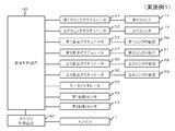
- FIG. 2 is a block diagram schematically showing an electronic control system of the vehicle transmission according to the first embodiment of the present invention.
- the vehicle transmission is an apparatus including a transmission 10 (dual clutch transmission) that performs a shift change by mounting two clutches.
- the vehicle transmission device includes a transmission 10 and a transmission control device 50.
- Engine 1 is an internal combustion engine that explodes and burns fuel in a cylinder and works with its thermal energy (see FIGS. 1 and 2).
- the engine 1 includes an injector actuator (not shown) that adjusts the fuel injection amount, an igniter actuator that adjusts the ignition timing of the fuel, and the like, and is controlled by the engine control device 60.
- the rotational power of the engine 1 is transmitted to the first clutch 11 and the second clutch 12 of the transmission 10 via the rotary shaft 2.
- the transmission 10 is a dual clutch transmission disposed on a power transmission path between the engine 1 and the differential device 30.
- the transmission 10 includes a motor generator 25 that rotates integrally with the second input shaft 18.
- the transmission 10 includes a first clutch 11, a second clutch 12, a first input shaft 13, a first speed drive gear 14, a third speed drive gear 15, a fifth speed drive gear 16, and a reverse drive gear 17.
- the first clutch 11 is a device that interrupts transmission of rotational power from the rotary shaft 2 of the engine 1 to the first input shaft 13.
- the intermittent operation of the first clutch 11 is performed by a first clutch actuator 51 that is driven and controlled by the transmission control device 50.
- the second clutch 12 is a device that interrupts transmission of rotational power from the rotary shaft 2 of the engine 1 to the second input shaft 18.
- the intermittent operation of the second clutch 12 is performed by a second clutch actuator 52 that is driven and controlled by the transmission control device 50.
- the first input shaft 13 is a rotating shaft for transmitting rotational power to the odd-numbered and reverse drive gears 14 to 17, and is connected to the first clutch 11.
- a first speed drive gear 14, a third speed drive gear 15, a fifth speed drive gear 16, and a reverse drive gear 17 are mounted on the first input shaft 13 so as to be idled from one side (the right side in FIG. 1).
- These drive gears 14 to 17 are meshed with the corresponding driven gears 23 a to 23 c and the idler gear 22.
- the second input shaft 18 is a rotary shaft for transmitting rotational power to the even-numbered drive gears 19 to 21, and is connected to the second clutch 12.
- a second speed drive gear 19, a fourth speed drive gear 20, and a sixth speed drive gear 21 are mounted on the second input shaft 18 so as to be idled from one side (the right side in FIG. 1). These drive gears 19 to 21 are meshed with corresponding driven gears 24a to 24c.
- the second input shaft 18 is connected to the rotation shaft of the motor generator 25 so as not to be relatively rotatable.
- the idler gear 22 is a gear that realizes a reverse shift stage by being meshed with the reverse drive gear 17 and the reverse driven gear 23d according to the position in the axial direction.
- the idler gear 22 is arranged at the neutral position at the forward gear speed other than reverse, disengaged, and idles.
- the first output shaft 23 is integrally provided with a first speed driven gear 23a, a third speed driven gear 23b, a fifth speed driven gear 23c, a reverse driven gear 23d, and a drive gear 23e from one side (right side in FIG. 1). .
- the driven gears 23a to 23c, the reverse driven gear 23d, and the driving gear 23e are meshed with the corresponding driving gears 14 to 16, the idler gear 22, and the driven gear 31.
- the second output shaft 24 is integrally provided with a second speed driven gear 24a, a fourth speed driven gear 24b, a sixth speed driven gear 24c, and a drive gear 24d from one side (right side in FIG. 1).
- the driven gears 24 a to 24 c and the driving gear 24 d are meshed with the corresponding driving gears 19 to 21 and the driven gear 31.
- the motor generator 25 is a synchronous generator motor that can be driven as a generator as well as a generator.
- the rotation shaft of the motor generator 25 is connected to the second input shaft 18.
- the motor generator 25 is driven and controlled by the transmission control device 50.
- the rotating shaft of the motor generator 25 is not limited to being connected to the second input shaft 18, but is a predetermined rotating element on the output side of the clutches 11 and 12 (for example, the first input shaft 13, the output shaft 23, 24) or the like.
- the first sync device 26 is a device for switching between the first speed and the third speed.
- the first synchronizer 26 synchronizes the rotational speeds of the first input shaft 13 and the first speed drive gear 14 or the third speed drive gear 15 to synchronize the first input shaft 13 with the first speed drive gear 14 or the third speed drive gear 15. Rotate together.
- the switching operation and the synchronization operation of the first synchronization device 26 are performed by a first transmission actuator 53 that is driven and controlled by the transmission control device 50.
- the second sync device 27 is a device for switching between the second speed and the fourth speed.
- the second synchronizer 27 synchronizes the rotational speeds of the second input shaft 18 and the second-speed drive gear 19 or the fourth-speed drive gear 20 to synchronize the second input shaft 18 with the second-speed drive gear 19 or the fourth-speed drive gear 20. Rotate together.
- the switching operation and the synchronization operation of the second synchronizer 27 are performed by a second speed change actuator 54 that is driven and controlled by the speed change control device 50.
- the third sync device 28 is a device for switching between 5th speed and reverse.
- the third synchronizer 28 synchronizes the rotational speeds of the first input shaft 13 and the fifth speed drive gear 16 or the reverse drive gear 17 so that the first input shaft 13 and the fifth speed drive gear 16 or the reverse drive gear 17 are integrated. Rotate.
- the switching operation and the synchronizing operation of the third synchronizer 28 are performed by a third shift actuator 55 that is driven and controlled by the shift control device 50.
- the fourth sync device 29 is a device for selecting the sixth speed.
- the fourth synchronizer 29 synchronizes the rotational speeds of the second input shaft 18 and the sixth speed drive gear 21 and rotates the second input shaft 18 and the sixth speed drive gear 21 integrally.
- the selection operation and the synchronization operation of the fourth synchronizer 29 are performed by a fourth shift actuator 56 that is driven and controlled by the shift control device 50.
- the differential device 30 is a device that absorbs a difference in rotational speed between the left and right shafts 32 and 33 and enables smooth rolling running.
- the differential device 30 outputs the rotational power input from the driven gear 31 to the drive wheels 40 and 41 via the shafts 32 and 33 in a differential manner.
- the rotation sensor 42 is a sensor that detects the rotation speed (N1) of the shaft 32.
- the rotation sensor 43 is a sensor that detects the number of rotations (N2) of the shaft 33.
- the rotation sensors 42 and 43 are electrically connected to the transmission control device 50.
- a rotation sensor for an antilock brake system (ABS) can be used as the rotation sensors 42 and 43.
- the shift control device 50 is a controller that controls the clutch actuators 51 and 52, the shift actuators 53 to 56, and the motor generator 25.
- the shift control device 50 has a computer function of performing control based on a program.
- the transmission control device 50 stores a program, a database, a map, and the like.
- the shift control device 50 is electrically connected to a shift lever load sensor (not shown) that detects a load (shift lever load) generated when a shift lever (not shown) of the transmission 10 is operated. The detection signal is input.
- the transmission control device 50 is electrically connected to rotation sensors 42 and 43 that detect the rotational speeds of the shafts 32 and 33, and a detection signal thereof is input.
- the shift control device 50 is electrically connected to a gear position sensor (not shown) that detects the actual gear position of the transmission 10 and receives a detection signal thereof.
- the transmission control device 50 is electrically connected to a transmission input shaft rotational speed sensor (not shown) that detects the rotational speeds of the input shafts 13 and 18 of the transmission 10, and the detection signal is input.
- the shift control device 50 is electrically connected to an engine speed sensor (not shown) that detects the speed of the rotating shaft 2 of the engine 1 and receives a detection signal thereof.
- the speed change control device 50 operates in a necessary operating state (shift position from a shift lever load sensor (not shown), input shaft speed from a transmission input shaft speed sensor (not shown), output shaft speed).
- the shift control device 50 controls the first clutch 11 by controlling the first clutch actuator 51 by driving the first clutch actuator 51.
- the transmission control device 50 controls the on / off state of the second clutch 12 by controlling the driving of the second clutch actuator 52.
- the shift control device 50 controls switching and synchronization of the first synchronizer 26 by controlling the drive of the first shift actuator 53.
- the shift control device 50 controls the switching and synchronization of the second synchronizer 27 by controlling the drive of the second shift actuator 54.
- the shift control device 50 controls the switching and synchronization of the third synchronizer 28 by drivingly controlling the third shift actuator 55.
- the shift control device 50 controls the selection and synchronization of the fourth synchronizer 29 by controlling the drive of the fourth shift actuator 56.
- the control operation of the transmission control device 50 will be described later.
- the engine control device 60 is a computer that controls the engine 1.
- the engine control device 60 includes an engine operating state (accelerator opening degree from an accelerator pedal sensor (not shown), an engine speed Ne from an engine speed sensor (not shown), an ignition switch (not shown) required for control. ) Is collected according to a predetermined program, and an actuator such as an injector (not shown) or an igniter (not shown) is controlled.
- the engine control device 60 is electrically connected to the transmission control device 50, and can provide information necessary for the transmission control device 50 (engine speed Ne, accelerator opening, etc.) to the transmission control device 50. is there.
- the output shafts 23 and 24 and the driven gears 23a to 23d and 24a to 24c can be synchronized with each other, and the input shafts 11 and 18 and the drive gears 14 to 17, 19 can be synchronized.
- 21 may be integrated.
- FIG. 3 is a schematic diagram showing a power transmission path when the vehicle including the vehicle transmission device according to the first embodiment of the present invention is traveling at the first speed.
- FIG. 4 is a timing chart schematically showing the operation of the vehicle transmission according to the first embodiment of the present invention.
- the speed change control device controls the first clutch actuator (51 in FIG. 2) to engage the first clutch 11, and synchronizes the first input shaft 13 and the first speed drive gear 14.
- the first speed change actuator (53 in FIG. 2) is controlled so that the second clutch 12 is not engaged, the second clutch actuator (52 in FIG. 2) is controlled, and the second input shaft 18 and the second speed drive are controlled.
- the second speed change actuator (54 in FIG. 2) is controlled to synchronize the gear 19, the other speed change actuators (55 and 56 in FIG.
- the shift control apparatus When shifting the gear stage from the first speed to the second speed, the shift control apparatus (50 in FIG. 2) opens the clutch clutch (51 in FIG. 2) so as to engage the second clutch 12 while releasing the first clutch 11. 52), and after the shift is completed, the first speed change actuator (53 in FIG. 2) is controlled to synchronize the first input shaft 13 and the third speed drive gear 15. The same applies to other shifts.
- the shift control device controls the motor generator 25 to perform regeneration (see FIG. 4).
- the rotational power input to the differential device 30 is suppressed, and the rotational difference (
- the speed change control device (50 in FIG. 2) turns off the motor generator 25. Since the rotational power is input to the motor generator 25 at any shift stage and during the shift, the regenerative control of the motor generator 25 can be performed by the shift control device (50 in FIG. 2).
- the rotation difference between the drive wheels 40 and 41 during traveling such as a rough road is suppressed by regeneration of the motor generator 25, so that the engine rotation is prevented from blowing up and the drive wheels 40 and 41 are grounded again.
- the slip and the large behavior of the vehicle are suppressed, the running stability is improved, and regenerative energy can be obtained.
Landscapes
- Engineering & Computer Science (AREA)
- Transportation (AREA)
- Mechanical Engineering (AREA)
- Chemical & Material Sciences (AREA)
- Combustion & Propulsion (AREA)
- Automation & Control Theory (AREA)
- Power Engineering (AREA)
- Control Of Transmission Device (AREA)
- Structure Of Transmissions (AREA)
Abstract
悪路走行などにおいても走行安定性を向上させることが可能なデュアルクラッチトランスミッションを含む車両用変速装置を提供すること。入力軸と、入力軸からの回転動力が変速可能に伝達される出力軸と、エンジンから入力軸への回転動力の伝達を断続するクラッチと、出力軸の両方と回転動力伝達可能に接続されたディファレンシャル装置を介して差動可能に駆動される駆動輪の回転数を検出する回転センサと、入力軸と一体回転するモータジェネレータと、クラッチの断続を制御するとともに、入力軸と出力軸間、及び入力軸と出力軸間の変速を制御し、かつ、回転センサの信号に基づいてモータジェネレータの回生動作を制御する変速制御装置と、を備える。
Description
[関連出願の記載]
本発明は、日本国特許出願:特願2009-218648号(2009年9月24日出願)の優先権主張に基づくものであり、同出願の全記載内容は引用をもって本書に組み込み記載されているものとする。
本発明は、二つのクラッチを搭載することでシフトチェンジを行う変速機(デュアルクラッチトランスミッション)を含む車両用変速装置に関し、特に、変速機においてモータジェネレータを搭載した車両用変速装置に関する。
本発明は、日本国特許出願:特願2009-218648号(2009年9月24日出願)の優先権主張に基づくものであり、同出願の全記載内容は引用をもって本書に組み込み記載されているものとする。
本発明は、二つのクラッチを搭載することでシフトチェンジを行う変速機(デュアルクラッチトランスミッション)を含む車両用変速装置に関し、特に、変速機においてモータジェネレータを搭載した車両用変速装置に関する。
従来の変速機において、手動変速機におけるクラッチ操作を自動化したセミオートマチックトランスミッションがある。セミオートマチックトランスミッションのうちデュアルクラッチトランスミッション(DCT)は、エンジンの出力軸の駆動力を、奇数変速段(1速、3速、5速、リバース)の伝達経路と、偶数変速段(2速、4速、6速)の伝達経路とに分離し、それぞれの伝達経路に一つずつエンジンからの駆動を伝達するクラッチが設けられている。デュアルクラッチトランスミッション(DCT)では、クラッチがつながっている側の変速機構がタイヤを駆動して、クラッチがつながっていない側の変速機構は変速するための準備を行い、変速前段側のクラッチを開放しながら、変速後段側のクラッチを締結することにより変速を行う。デュアルクラッチトランスミッション(DCT)によれば、マニュアルトランスミッション(MT)のダイレクト感とオートマチックトランスミッション(AT)のイージーさ、スムーズさを兼ね備え、変速途中のトルク抜けのない加速感のある変速が可能である。
従来のデュアルクラッチトランスミッションに関して、二つの入力軸と、二つのクラッチと、少なくとも一つの第一の駆動軸と、少なくとも一つの第二の駆動軸とを有し、第一の入力軸が、第一のクラッチと作用する際に接続可能であり、第二の入力軸が、第二のクラッチと作用する際に接続可能であり、第一の駆動軸が、第二の駆動軸の下で、かつ入力軸の上に配置されているか、或いはその逆に配置されており、入力軸と駆動軸が、互いに係合する歯車を有し、少なくとも二つの歯車が、一つのシフト段を構成し、一つのシフト段の少なくとも一つの歯車が、投入と解放の両方又は一方が可能な可動歯車として構成され、他方の歯車が、有利には、固定歯車として構成されており、各駆動軸が、回転力を車軸駆動部に伝達するための駆動部歯車を有し、後退シフト段を実現するために、更なる軸が配備されているデュアルクラッチトランスミッションが開示されている(特許文献1参照)。これにより、柔軟な利用を可能とするとともに、特にコンパクトな構造形態を実現するとしている。
なお、上記特許文献1の全開示内容はその引用をもって本書に繰込み記載する。以下の分析は、本発明によって与えられたものである。
しかしながら、悪路走行などにより片側のタイヤが宙に浮いて空転するとエンジン回転が吹き上がり、再びタイヤが接地した時にスリップや車両の大きな挙動を伴い、走行安定性が損なわれる。特に、デュアルクラッチトランスミッションの変速動作では変速前段側のクラッチを半クラッチ状態にして変速後段側のクラッチを係合するため、片側のタイヤが宙に浮いて空転した時に変速すると、変速途中のトルク抜けがない分、エンジン回転の吹き上がりが大きくなり、再びタイヤが接地した時のスリップや車両の大きな挙動が大きくなり、走行安定性が大きく損なわれるおそれがある。
しかしながら、悪路走行などにより片側のタイヤが宙に浮いて空転するとエンジン回転が吹き上がり、再びタイヤが接地した時にスリップや車両の大きな挙動を伴い、走行安定性が損なわれる。特に、デュアルクラッチトランスミッションの変速動作では変速前段側のクラッチを半クラッチ状態にして変速後段側のクラッチを係合するため、片側のタイヤが宙に浮いて空転した時に変速すると、変速途中のトルク抜けがない分、エンジン回転の吹き上がりが大きくなり、再びタイヤが接地した時のスリップや車両の大きな挙動が大きくなり、走行安定性が大きく損なわれるおそれがある。
本発明の主な課題は、悪路走行などにおいても走行安定性を向上させることが可能なデュアルクラッチトランスミッションを含む車両用変速装置を提供することである。
本発明の一視点においては、車両用変速装置において、第1入力軸及び第2入力軸と、前記第1入力軸からの回転動力が変速可能に伝達される第1出力軸と、前記第2入力軸からの回転動力が変速可能に伝達される第2出力軸と、エンジンから前記第1入力軸への回転動力の伝達を断続する第1クラッチと、前記エンジンから前記第2入力軸への回転動力の伝達を断続する第2クラッチと、前記第1出力軸及び前記第2出力軸の両方と回転動力伝達可能に接続されたディファレンシャル装置を介して差動可能に駆動される2つの駆動輪の一方の回転数を検出する第1回転センサと、前記2つの駆動輪の他方の回転数を検出する第2回転センサと、前記第1クラッチ及び前記第2クラッチよりも出力側の所定の回転要素と一体又は噛合して回転するモータジェネレータと、前記第1クラッチ及び前記第2クラッチの断続を制御するとともに、前記第1入力軸と第1出力軸間、及び前記第2入力軸と第2出力軸間の変速を制御し、かつ、前記第1回転センサ及び前記第2回転センサの信号に基づいて前記モータジェネレータの回生動作を制御する制御装置と、を備えることである。
本発明によれば、悪路など走行時の2つの駆動輪の回転差をモータジェネレータの回生で抑制することにより、エンジン回転が吹き上がりが抑えられ、再び駆動輪が接地した時のスリップや車両の大きな挙動が抑えられ、走行安定性が向上するとともに、回生エネルギーも得ることができる。
本発明の実施形態に係る車両用変速装置では、第1入力軸(図1の13)及び第2入力軸(図1の18)と、前記第1入力軸(図1の13)からの回転動力が変速可能に伝達される第1出力軸(図1の23)と、前記第2入力軸(図1の18)からの回転動力が変速可能に伝達される第2出力軸(図1の24)と、エンジン(図1の1)から前記第1入力軸(図1の13)への回転動力の伝達を断続する第1クラッチ(図1の11)と、前記エンジン(図1の1)から前記第2入力軸(図1の18)への回転動力の伝達を断続する第2クラッチ(図1の12)と、前記第1出力軸(図1の23)及び前記第2出力軸(図1の24)の両方と回転動力伝達可能に接続されたディファレンシャル装置(図1の30)を介して差動可能に駆動される2つの駆動輪(図1の40、41)の一方の回転数を検出する第1回転センサ(図1の42)と、前記2つの駆動輪(図1の40、41)の他方の回転数を検出する第2回転センサ(図1の43)と、前記第1クラッチ(図1の11)及び前記第2クラッチ(図1の12)よりも出力側の所定の回転要素(例えば、図1の13、18、23、24等)と一体又は噛合して回転するモータジェネレータ(図1の25)と、前記第1クラッチ(図1の11)及び前記第2クラッチ(図1の12)の断続を制御するとともに、前記第1入力軸(図1の13)と第1出力軸(図1の23)間、及び前記第2入力軸(図1の18)と第2出力軸(図1の24)間の変速を制御し、かつ、前記第1回転センサ(図1の42)及び前記第2回転センサ(図1の43)の信号に基づいて前記モータジェネレータ(図1の25)の回生動作を制御する制御装置(図2の50)と、を備える。
本発明の実施例1に係る車両用変速装置について図面を用いて説明する。図1は、本発明の実施例1に係る車両用変速装置の変速機を含む動力伝達装置の構成を示した模式図である。図2は、本発明の実施例1に係る車両用変速装置の電子制御系を模式的に示したブロック図である。
図1を参照すると、車両用変速装置は、二つのクラッチを搭載することでシフトチェンジを行う変速機10(デュアルクラッチトランスミッション)を含む装置である。車両用変速装置は、変速機10と、変速制御装置50と、を有する。
エンジン1は、シリンダー内で燃料を爆発燃焼させ、その熱エネルギーによって仕事をする内燃機関である(図1、図2参照)。エンジン1は、燃料の噴出量を調整するインジェクタアクチュエータ(図示せず)、燃料の点火時期を調整するイグナイタアクチュエータ等を有し、エンジン制御装置60によって制御される。エンジン1の回転動力は、回転軸2を介して変速機10の第1クラッチ11及び第2クラッチ12に伝達される。
変速機10は、エンジン1とディファレンシャル装置30の間の動力伝達経路上に配設されたデュアルクラッチトランスミッションである。変速機10は、第2入力軸18と一体的に回転するモータジェネレータ25を備える。変速機10は、第1クラッチ11と、第2クラッチ12と、第1入力軸13と、1速駆動ギヤ14と、3速駆動ギヤ15と、5速駆動ギヤ16と、後退駆動ギヤ17と、第2入力軸18と、2速駆動ギヤ19と、4速駆動ギヤ20と、6速駆動ギヤ21と、アイドラギヤ22と、第1出力軸23と、第2出力軸24と、モータジェネレータ25と、第1シンクロ装置26と、第2シンクロ装置27と、第3シンクロ装置28と、第4シンクロ装置29と、を有する。
第1クラッチ11は、エンジン1の回転軸2から第1入力軸13への回転動力の伝達を断続する装置である。第1クラッチ11の断続動作は、変速制御装置50によって駆動制御される第1クラッチアクチュエータ51によって行われる。
第2クラッチ12は、エンジン1の回転軸2から第2入力軸18への回転動力の伝達を断続する装置である。第2クラッチ12の断続動作は、変速制御装置50によって駆動制御される第2クラッチアクチュエータ52によって行われる。
第1入力軸13は、奇数段及び後退用の駆動ギヤ14~17に回転動力を伝達するための回転軸であり、第1クラッチ11に連結されている。第1入力軸13には、一側(図1の右側)から1速駆動ギヤ14、3速駆動ギヤ15、5速駆動ギヤ16、及び後退駆動ギヤ17が空転可能に装着されている。これらの駆動ギヤ14~17は、対応する従動ギヤ23a~23c、アイドラギヤ22と噛合連結されている。
第2入力軸18は、偶数段の駆動ギヤ19~21に回転動力を伝達するための回転軸であり、第2クラッチ12に連結されている。第2入力軸18には、一側(図1の右側)から2速駆動ギヤ19、4速駆動ギヤ20、及び6速駆動ギヤ21が空転可能に装着されている。これらの駆動ギヤ19~21は、対応する従動ギヤ24a~24cと噛合連結されている。第2入力軸18は、モータジェネレータ25の回転軸と相対回転不能に連結されている。
アイドラギヤ22は、軸方向の位置に応じて後退駆動ギヤ17及び後退従動ギヤ23dに噛合連結されることで後退の変速段を実現するギヤである。アイドラギヤ22は、後退以外の前進変速段では中立位置に配置されて連結が解除され空転する。
第1出力軸23は、一側(図1の右側)から1速従動ギヤ23a、3速従動ギヤ23b、5速従動ギヤ23c、後退従動ギヤ23d、駆動ギヤ23eが一体的に設けられている。従動ギヤ23a~23c、後退従動ギヤ23d、駆動ギヤ23eは、対応する駆動ギヤ14~16、アイドラギヤ22、従動ギヤ31と噛合連結されている。
第2出力軸24は、一側(図1の右側)から2速従動ギヤ24a、4速従動ギヤ24b、6速従動ギヤ24c、駆動ギヤ24dが一体的に設けられている。従動ギヤ24a~24c、駆動ギヤ24dは、対応する駆動ギヤ19~21、従動ギヤ31と噛合連結されている。
モータジェネレータ25は、発電機として駆動することができると共に電動機として駆動できる同期発電電動機である。モータジェネレータ25の回転軸は、第2入力軸18と連結されている。モータジェネレータ25は、変速制御装置50によって駆動制御される。なお、モータジェネレータ25の回転軸は、第2入力軸18と連結される場合に限らず、クラッチ11、12よりも出力側の所定の回転要素(例えば、第1入力軸13、出力軸23、24等)と一体又は噛合して回転するようにしてもよい。
第1シンクロ装置26は、1速と3速を切り換えるための装置である。第1シンクロ装置26は、第1入力軸13と1速駆動ギヤ14又は3速駆動ギヤ15との回転速度を同期させて、第1入力軸13と1速駆動ギヤ14又は3速駆動ギヤ15を一体回転させる。第1シンクロ装置26の切換動作及び同期動作は、変速制御装置50によって駆動制御される第1変速アクチュエータ53によって行われる。
第2シンクロ装置27は、2速と4速を切り換えるための装置である。第2シンクロ装置27は、第2入力軸18と2速駆動ギヤ19又は4速駆動ギヤ20との回転速度を同期させて、第2入力軸18と2速駆動ギヤ19又は4速駆動ギヤ20を一体回転させる。第2シンクロ装置27の切換動作及び同期動作は、変速制御装置50によって駆動制御される第2変速アクチュエータ54によって行われる。
第3シンクロ装置28は、5速と後退を切り換えるための装置である。第3シンクロ装置28は、第1入力軸13と5速駆動ギヤ16又は後退駆動ギヤ17との回転速度を同期させて、第1入力軸13と5速駆動ギヤ16又は後退駆動ギヤ17を一体回転させる。第3シンクロ装置28の切換動作及び同期動作は、変速制御装置50によって駆動制御される第3変速アクチュエータ55によって行われる。
第4シンクロ装置29は、6速を選択するための装置である。第4シンクロ装置29は、第2入力軸18と6速駆動ギヤ21との回転速度を同期させて、第2入力軸18と6速駆動ギヤ21を一体回転させる。第4シンクロ装置29の選択動作及び同期動作は、変速制御装置50によって駆動制御される第4変速アクチュエータ56によって行われる。
ディファレンシャル装置30は、左右のシャフト32、33の回転数の差を吸収し、円滑な転がり走行を可能にする装置である。ディファレンシャル装置30は、従動ギヤ31から入力された回転動力を、シャフト32、33を介して駆動輪40、41に向けて差動可能に出力する。
回転センサ42は、シャフト32の回転数(N1)を検出するセンサである。回転センサ43は、シャフト33の回転数(N2)を検出するセンサである。回転センサ42、43は、変速制御装置50と電気的に接続されている。回転センサ42、43には、アンチロックブレーキシステム(ABS;Antilock Brake System)用の回転センサを用いることができる。
変速制御装置50は、クラッチアクチュエータ51、52、変速アクチュエータ53~56、及びモータジェネレータ25を制御するコントローラである。変速制御装置50は、プログラムに基づいて制御を行うコンピュータ機能を有する。変速制御装置50は、プログラム、データベース及びマップ等を記憶する。変速制御装置50は、変速機10のシフトレバー(図示せず)が操作されたときに生じる荷重(シフトレバー荷重)を検出するシフトレバー荷重センサ(図示せず)と電気的に接続されており、その検出信号が入力される。変速制御装置50は、シャフト32、33の回転数を検出する回転センサ42、43と電気的に接続されており、その検出信号が入力される。変速制御装置50は、実際の変速機10の変速段を検出するギヤ位置センサ(図示せず)と電気的に接続されており、その検出信号が入力される。変速制御装置50は、変速機10の入力軸13、18の回転数を検出する変速機入力軸回転数センサ(図示せず)と電気的に接続されており、その検出信号が入力される。変速制御装置50は、エンジン1の回転軸2の回転数を検出するエンジン回転数センサ(図示せず)と電気的に接続されており、その検出信号が入力される。変速制御装置50は、制御に必要な運転状態(シフトレバー荷重センサ(図示せず)からのシフトポジション、変速機入力軸回転数センサ(図示せず)からの入力軸回転数、出力軸回転数センサ(図示せず)からの出力軸回転数、エンジン制御装置60からのエンジン回転数等)に関する情報を収集し、あらかじめ定められたプログラムに従って計算を行い、クラッチアクチュエータ51、52、変速アクチュエータ53~56、及びモータジェネレータ25を制御する。
変速制御装置50は、第1クラッチアクチュエータ51を駆動制御することにより、第1クラッチ11の断続を制御する。変速制御装置50は、第2クラッチアクチュエータ52を駆動制御することにより、第2クラッチ12の断続を制御する。変速制御装置50は、第1変速アクチュエータ53を駆動制御することにより、第1シンクロ装置26の切換及び同期を制御する。変速制御装置50は、第2変速アクチュエータ54を駆動制御することにより、第2シンクロ装置27の切換及び同期を制御する。変速制御装置50は、第3変速アクチュエータ55を駆動制御することにより、第3シンクロ装置28の切換及び同期を制御する。変速制御装置50は、第4変速アクチュエータ56を駆動制御することにより、第4シンクロ装置29の選択及び同期を制御する。なお、変速制御装置50の制御動作については、後述する。
エンジン制御装置60は、エンジン1を制御するコンピュータである。エンジン制御装置60は、制御に必要なエンジン運転状態(アクセルペダルセンサ(図示せず)からのアクセル開度、エンジン回転数センサ(図示せず)からのエンジン回転数Ne、イグニッションスイッチ(図示せず)のオン・オフ状態等)に関する情報を収集し、あらかじめ定められたプログラムに従って計算を行い、インジェクタ(図示せず)、イグナイタ(図示せず)等のアクチュエータを制御する。エンジン制御装置60は、変速制御装置50と電気的に接続されており、変速制御装置50において必要な情報(エンジン回転数Ne、アクセル開度など)を変速制御装置50に提供することが可能である。
なお、図1の変速機10では入力軸11、18と駆動ギヤ14~17、19~21の間で同期可能な構成とし、かつ、出力軸23、24と従動ギヤ23a~23d、24a~24cが一体的な構成となっているが、出力軸23、24と従動ギヤ23a~23d、24a~24cの間で同期可能な構成とし、かつ、入力軸11、18と駆動ギヤ14~17、19~21が一体的な構成としてもよい。
次に、本発明の実施例1に係る車両用変速装置の動作について図面を用いて説明する。図3は、本発明の実施例1に係る車両用変速装置を含む車両が1速段で走行しているときの動力伝達経路を示した模式図である。図4は、本発明の実施例1に係る車両用変速装置の動作を模式的に示したタイミングチャートである。
図3を参照すると、例えば、車両用変速装置を含む車両が1速段で走行するとき、クラッチがつながっている側がタイヤを駆動して、クラッチがつながっていない側は変速するための準備を行う。すなわち、変速制御装置(図2の50)は、第1クラッチ11を係合させるように第1クラッチアクチュエータ(図2の51)を制御し、第1入力軸13と1速駆動ギヤ14を同期させるように第1変速アクチュエータ(図2の53)を制御し、第2クラッチ12を係合させないように第2クラッチアクチュエータ(図2の52)を制御し、第2入力軸18と2速駆動ギヤ19を同期させるように第2変速アクチュエータ(図2の54)を制御し、その他の変速アクチュエータ(図2の55、56)をニュートラルとし、モータジェネレータ25をOFFとする。これにより、エンジン1の回転動力は、図3の太字実線のように、回転軸2、第1クラッチ11、第1入力軸13、第1シンクロ装置26、1速駆動ギヤ14、1速従動ギヤ23a、第1出力軸23、駆動ギヤ23e、従動ギヤ31、ディファレンシャル装置30、シャフト33、32の順に伝達して、駆動輪40、41を駆動する。このとき、従動ギヤ31は駆動ギヤ24dと噛み合っているため、従動ギヤ31の回転動力は、図3の太字点線のように、駆動ギヤ24d、第2出力軸24、2速従動ギヤ24a、2速駆動ギヤ19、第2シンクロ装置27、第2入力軸18の順に伝達して、モータジェネレータ25に入力される。
ギヤ段を1速から2速に変速するときは、変速制御装置(図2の50)は、第1クラッチ11を開放しながら、第2クラッチ12を締結するようにクラッチアクチュエータ(図2の51、52)を制御し、変速完了後、第1入力軸13と3速駆動ギヤ15を同期させるように第1変速アクチュエータ(図2の53)を制御することになる。その他の変速についても同様である。
図3のように車両用変速装置を含む車両が1速段で駆動輪40、41のグリップが悪い路面を走行しているときに、駆動輪40、41の一方が空転すると、駆動輪40、41の回転差(|N1-N2|)が発生し、第1回転センサ42で検出された駆動輪40の回転数N1と、第2回転センサ43で検出された駆動輪41の回転数N2と、が変速制御装置(図2の50)に入力される。変速制御装置(図2の50)は、入力された回転数N1、N2に基づいて、駆動輪40、41の回転差(|N1-N2|)がしきい値以上であるか否かを監視する。|N1-N2|がしきい値以上になると、変速制御装置(図2の50)は、モータジェネレータ25で回生を行うように制御する(図4参照)。モータジェネレータ25を回生させることで、ディファレンシャル装置30に入力される回転動力が抑えられ、駆動輪40、41の回転差(|N1-N2|)を抑制することができる。|N1-N2|がしきい値未満となると、変速制御装置(図2の50)は、モータジェネレータ25をOFF状態にする。なお、モータジェネレータ25にはどの変速段及び変速途中でも回転動力が入力されるため、変速制御装置(図2の50)によるモータジェネレータ25の回生制御を行うことができる。
実施例1によれば、悪路など走行時の駆動輪40、41の回転差をモータジェネレータ25の回生で抑制することにより、エンジン回転の吹き上がりが抑えられ、再び駆動輪40、41が接地した時のスリップや車両の大きな挙動が抑えられ、走行安定性が向上するとともに、回生エネルギーも得ることができる。また、モータジェネレータ25の回生により駆動輪40、41の回転差を抑制することで、エンジン1を制御して駆動輪40、41の回転差を抑制するよりも、迅速に安定化させることが可能である。
なお、上記の特許文献の各開示を、本書に引用をもって繰り込むものとする。本発明の全開示(請求の範囲を含む)の枠内において、さらにその基本的技術思想に基づいて、実施例ないし実施例の変更・調整が可能である。また、本発明の請求の範囲の枠内において種々の開示要素の多様な組み合わせないし選択が可能である。すなわち、本発明は、請求の範囲を含む全開示、技術的思想にしたがって当業者であればなし得るであろう各種変形、修正を含むことは勿論である。
1 エンジン
2 回転軸
10 変速機
11 第1クラッチ
12 第2クラッチ
13 第1入力軸
14 1速駆動ギヤ
15 3速駆動ギヤ
16 5速駆動ギヤ
17 後退駆動ギヤ
18 第2入力軸
19 2速駆動ギヤ
20 4速駆動ギヤ
21 6速駆動ギヤ
22 アイドラギヤ
23 第1出力軸
23a 1速従動ギヤ
23b 3速従動ギヤ
23c 5速駆動ギヤ
23d 後退駆動ギヤ
23e 駆動ギヤ
24 第2出力軸
24a 2速従動ギヤ
24b 4速従動ギヤ
24c 6速従動ギヤ
24d 駆動ギヤ
25 モータジェネレータ
26 第1シンクロ装置
27 第2シンクロ装置
28 第3シンクロ装置
29 第4シンクロ装置
30 ディファレンシャル装置
31 従動ギヤ
32、33 シャフト
40、41 駆動輪
42、43 回転センサ
50 変速制御装置
51 第1クラッチアクチュエータ
52 第2クラッチアクチュエータ
53 第1変速アクチュエータ
54 第2変速アクチュエータ
55 第3変速アクチュエータ
56 第4変速アクチュエータ
60 エンジン制御装置
Claims (5)
- 第1入力軸及び第2入力軸と、
前記第1入力軸からの回転動力が変速可能に伝達される第1出力軸と、
前記第2入力軸からの回転動力が変速可能に伝達される第2出力軸と、
エンジンから前記第1入力軸への回転動力の伝達を断続する第1クラッチと、
前記エンジンから前記第2入力軸への回転動力の伝達を断続する第2クラッチと、
前記第1出力軸及び前記第2出力軸の両方と回転動力伝達可能に接続されたディファレンシャル装置を介して差動可能に駆動される2つの駆動輪の一方の回転数を検出する第1回転センサと、
前記2つの駆動輪の他方の回転数を検出する第2回転センサと、
前記第1クラッチ及び前記第2クラッチよりも出力側の所定の回転要素と一体又は噛合して回転するモータジェネレータと、
前記第1クラッチ及び前記第2クラッチの断続を制御するとともに、前記第1入力軸と第1出力軸間、及び前記第2入力軸と第2出力軸間の変速を制御し、かつ、前記第1回転センサ及び前記第2回転センサの信号に基づいて前記モータジェネレータの回生動作を制御する制御装置と、
を備える車両用変速装置。 - 前記モータジェネレータの回転軸は、前記第1入力軸又は前記第2入力軸に連結されている請求項1記載の車両用変速装置。
- 前記第1回転センサ及び前記第2回転センサは、アンチロックブレーキシステム用の回転センサである請求項1又は2記載の車両用変速装置。
- 前記制御装置は、前記第1回転センサで検出された第1回転数と前記第2回転センサで検出された第2回転数の絶対差が、予め設定されたしきい値以上となっているときに前記モータジェネレータを回生させるように制御する請求項1乃至3のいずれか一に記載の車両用変速装置。
- 前記第1入力軸及び前記第1出力軸の一方の軸に固定された複数の第1固定ギヤと、
前記第1入力軸及び前記第1出力軸の他方の軸と相対回転可能に配されるとともに対応する前記第1固定ギヤと噛み合う複数の第1可動ギヤと、
前記第1可動ギヤを前記第1入力軸及び前記第1出力軸の他方の軸に同期させることが可能な複数の第1のシンクロ装置と、
前記第2入力軸及び前記第2出力軸の一方の軸に固定された複数の第2固定ギヤと、
前記第2入力軸及び前記第2出力軸の他方の軸と相対回転可能に配されるとともに対応する前記第2固定ギヤと噛み合う複数の第2可動ギヤと、
前記第2可動ギヤを前記第2入力軸及び前記第2出力軸の他方の軸に同期させることが可能な複数の第2のシンクロ装置と、
を備え、
前記制御装置は、前記第1のシンクロ装置及び前記第2のシンクロ装置の同期を制御する請求項1乃至4のいずれか一に記載の車両用変速装置。
Priority Applications (2)
| Application Number | Priority Date | Filing Date | Title |
|---|---|---|---|
| EP10818757.6A EP2481948B1 (en) | 2009-09-24 | 2010-09-17 | Shift device for vehicle |
| CN201080042580.0A CN102656387B (zh) | 2009-09-24 | 2010-09-17 | 车辆用变速装置 |
Applications Claiming Priority (2)
| Application Number | Priority Date | Filing Date | Title |
|---|---|---|---|
| JP2009-218648 | 2009-09-24 | ||
| JP2009218648A JP5436998B2 (ja) | 2009-09-24 | 2009-09-24 | 車両用変速装置 |
Publications (1)
| Publication Number | Publication Date |
|---|---|
| WO2011037084A1 true WO2011037084A1 (ja) | 2011-03-31 |
Family
ID=43795832
Family Applications (1)
| Application Number | Title | Priority Date | Filing Date |
|---|---|---|---|
| PCT/JP2010/066172 WO2011037084A1 (ja) | 2009-09-24 | 2010-09-17 | 車両用変速装置 |
Country Status (4)
| Country | Link |
|---|---|
| EP (1) | EP2481948B1 (ja) |
| JP (1) | JP5436998B2 (ja) |
| CN (1) | CN102656387B (ja) |
| WO (1) | WO2011037084A1 (ja) |
Cited By (1)
| Publication number | Priority date | Publication date | Assignee | Title |
|---|---|---|---|---|
| GB2543043A (en) * | 2015-10-05 | 2017-04-12 | Gm Global Tech Operations Llc | Vehicle power system |
Families Citing this family (7)
| Publication number | Priority date | Publication date | Assignee | Title |
|---|---|---|---|---|
| JP6186789B2 (ja) * | 2013-03-25 | 2017-08-30 | アイシン精機株式会社 | 車両用自動変速機の自動変速装置 |
| JP6278332B2 (ja) | 2013-04-22 | 2018-02-14 | スズキ株式会社 | 変速機の制御装置 |
| AT514542B1 (de) * | 2013-06-06 | 2015-04-15 | Avl List Gmbh | Doppelkupplungsgetriebe für ein Kraftfahrzeug |
| KR101551009B1 (ko) | 2013-12-18 | 2015-09-07 | 현대자동차주식회사 | Dct 차량의 변속 제어 방법 |
| CN103863085B (zh) * | 2014-03-18 | 2016-06-15 | 重庆大学 | 基于同步器耦合的双离合器式dct的混合动力驱动系统 |
| FR3052129A1 (fr) * | 2016-06-02 | 2017-12-08 | Peugeot Citroen Automobiles Sa | Dispositif de controle du couple transmis a un arbre secondaire d'une boite de vitesses de vehicule en presence d'une perte d'adherence |
| CN112937531B (zh) * | 2021-03-30 | 2023-01-03 | 柳工柳州传动件有限公司 | 一种工程机械的行车制动系统及制动方法 |
Citations (3)
| Publication number | Priority date | Publication date | Assignee | Title |
|---|---|---|---|---|
| JP2002234355A (ja) * | 2001-02-08 | 2002-08-20 | Fuji Heavy Ind Ltd | 4輪駆動車の制御装置 |
| JP2004284419A (ja) * | 2003-03-19 | 2004-10-14 | Nissan Motor Co Ltd | 差動制限制御装置 |
| JP2009166611A (ja) * | 2008-01-15 | 2009-07-30 | Toyota Motor Corp | ハイブリッド車両 |
Family Cites Families (6)
| Publication number | Priority date | Publication date | Assignee | Title |
|---|---|---|---|---|
| RU2223182C2 (ru) * | 1997-12-23 | 2004-02-10 | Лук Ламеллен унд Купплюнгсбау ГмбХ | Коробка передач |
| DE19940288C1 (de) * | 1999-08-25 | 2001-03-15 | Daimler Chrysler Ag | Doppelkupplungs-Mehrganggetriebe |
| JP2006002917A (ja) * | 2004-06-21 | 2006-01-05 | Aisin Ai Co Ltd | 複数のクラッチを持つ変速装置 |
| EP1714817A1 (de) * | 2005-04-19 | 2006-10-25 | Getrag Ford Transmissions GmbH | Hybrid-Doppelkupplungsgetriebe |
| DE102007010827A1 (de) * | 2007-03-06 | 2008-09-11 | Zf Friedrichshafen Ag | Verfahren zur Schaltsteuerung eines automatisierten Gruppengetriebes |
| JP4285571B2 (ja) * | 2007-09-27 | 2009-06-24 | トヨタ自動車株式会社 | 車両用駆動装置 |
-
2009
- 2009-09-24 JP JP2009218648A patent/JP5436998B2/ja not_active Expired - Fee Related
-
2010
- 2010-09-17 WO PCT/JP2010/066172 patent/WO2011037084A1/ja active Application Filing
- 2010-09-17 CN CN201080042580.0A patent/CN102656387B/zh not_active Expired - Fee Related
- 2010-09-17 EP EP10818757.6A patent/EP2481948B1/en not_active Not-in-force
Patent Citations (3)
| Publication number | Priority date | Publication date | Assignee | Title |
|---|---|---|---|---|
| JP2002234355A (ja) * | 2001-02-08 | 2002-08-20 | Fuji Heavy Ind Ltd | 4輪駆動車の制御装置 |
| JP2004284419A (ja) * | 2003-03-19 | 2004-10-14 | Nissan Motor Co Ltd | 差動制限制御装置 |
| JP2009166611A (ja) * | 2008-01-15 | 2009-07-30 | Toyota Motor Corp | ハイブリッド車両 |
Cited By (1)
| Publication number | Priority date | Publication date | Assignee | Title |
|---|---|---|---|---|
| GB2543043A (en) * | 2015-10-05 | 2017-04-12 | Gm Global Tech Operations Llc | Vehicle power system |
Also Published As
| Publication number | Publication date |
|---|---|
| CN102656387B (zh) | 2015-05-06 |
| JP5436998B2 (ja) | 2014-03-05 |
| EP2481948A4 (en) | 2014-05-21 |
| EP2481948A1 (en) | 2012-08-01 |
| CN102656387A (zh) | 2012-09-05 |
| EP2481948B1 (en) | 2016-05-11 |
| JP2011069390A (ja) | 2011-04-07 |
Similar Documents
| Publication | Publication Date | Title |
|---|---|---|
| JP5436998B2 (ja) | 車両用変速装置 | |
| JP5280327B2 (ja) | 車両用変速装置 | |
| US9586470B2 (en) | Powertrain for hybrid vehicle | |
| JP5942412B2 (ja) | 車両駆動装置 | |
| JP5847521B2 (ja) | デュアルクラッチ式自動変速機 | |
| CN103620271B (zh) | 双离合式变速器的控制方法、双离合式变速器以及搭载该双离合式变速器的车辆 | |
| JP5899018B2 (ja) | ハイブリッド車両の制御装置 | |
| JP6108313B2 (ja) | ハイブリッド車両におけるエンジン始動制御装置 | |
| JP4792883B2 (ja) | 複数クラッチ式変速機の制御装置 | |
| JP5372681B2 (ja) | 車両用変速装置 | |
| KR20110105636A (ko) | 듀얼 클러치 변속기 차량의 변속제어장치 및 방법 | |
| JP4720407B2 (ja) | 複数クラッチ式変速機の制御装置 | |
| JP4577073B2 (ja) | 複数クラッチ式変速機の制御装置 | |
| JP5902423B2 (ja) | 車両の動力伝達制御装置 | |
| JP2007057041A (ja) | 変速機の制御装置 | |
| JP4742928B2 (ja) | 複数クラッチ式変速機の変速制御装置 | |
| JP5634967B2 (ja) | ハイブリッド車両及びその制御方法 | |
| WO2020196541A1 (ja) | 自動変速機 | |
| JP2006226380A (ja) | ツインクラッチ式変速機の制御装置 | |
| JP5239760B2 (ja) | 車両の変速制御装置 | |
| JP2007092813A (ja) | 複数クラッチ式変速機の制御装置 | |
| JP2007092812A (ja) | 複数クラッチ式変速機の制御装置 | |
| JP2014109359A (ja) | 車両用駆動装置 | |
| JP2005102420A (ja) | モータ四輪駆動車のモータトルク制御装置 | |
| JP2019143788A (ja) | 車両用動力伝達装置 |
Legal Events
| Date | Code | Title | Description |
|---|---|---|---|
| WWE | Wipo information: entry into national phase |
Ref document number: 201080042580.0 Country of ref document: CN |
|
| 121 | Ep: the epo has been informed by wipo that ep was designated in this application |
Ref document number: 10818757 Country of ref document: EP Kind code of ref document: A1 |
|
| NENP | Non-entry into the national phase |
Ref country code: DE |
|
| WWE | Wipo information: entry into national phase |
Ref document number: 2010818757 Country of ref document: EP |